

Page 1

TI_Stream_NGCS_01_E_Rev02 1/18
Date of last update: Jun-20
Ref: TI_Stream_NGCS_01_E_Rev02
Application Engineering Europe
NEXT GENERATION CORESENSE™
FOR COPELAND STREAM™ COMPRESSORS
1 Introduction ............................................................................................................................................................ 3
2 Specifications ........................................................................................................................................................ 3
3 Next Generation CoreSense features ................................................................................................................... 4
4 Warnings, trips and lockouts ................................................................................................................................. 4
5 Protection features ................................................................................................................................................ 5
5.1 Oil protection ................................................................................................................................................. 5
5.1.1 Insufficient oil pressure protection ............................................................................................................ 5
5.1.2 Oil level protection (optional) .................................................................................................................... 5
5.2 Motor overheat protection ............................................................................................................................. 6
5.2.1 Static overheat protection ......................................................................................................................... 6
5.2.2 Dynamic overheat protection .................................................................................................................... 6
5.3 High discharge temperature protection......................................................................................................... 6
5.4 Current protection ......................................................................................................................................... 7
5.4.1 Locked rotor protection ............................................................................................................................. 7
5.4.2 MOC protection ......................................................................................................................................... 7
5.4.3 Switching frequency overstepping protection ........................................................................................... 7
5.4.4 MOC detection at first start ....................................................................................................................... 7
5.5 Phase / voltage monitoring ........................................................................................................................... 8
5.5.1 Missing phase protection / Phase failure protection ................................................................................. 8
5.5.2 Undervoltage protection ............................................................................................................................ 8
5.5.3 Overvoltage protection .............................................................................................................................. 8
5.5.4 Voltage imbalance protection ................................................................................................................... 8
5.5.5 Welded contactor protection ..................................................................................................................... 8
5.5.6 Part-winding protection ............................................................................................................................. 9
6 Variable frequency drive mode .............................................................................................................................. 9
7 Emergency mode .................................................................................................................................................. 9
8 LEDs on the terminal box cover .......................................................................................................................... 10
8.1 Compressor status codes ........................................................................................................................... 10
8.2 Failure alarms displayed by LEDs .............................................................................................................. 11
9 Alarm history ........................................................................................................................................................ 11
10 Reset button ........................................................................................................................................................ 12
11 Crankcase heater control .................................................................................................................................... 12
12 Power consumption measurement ...................................................................................................................... 12
13 Data port for communication with Next Gen CoreSense module app ................................................................ 12
Page 2

TI_Stream_NGCS_01_E_Rev02 2/18
13.1 Connectivity ................................................................................................................................................ 13
14 Modbus module (optional) ................................................................................................................................... 13
15 Next Gen CoreSense module app ...................................................................................................................... 13
16 Electrical connections .......................................................................................................................................... 14
16.1 Basic connections ....................................................................................................................................... 14
16.2 Wiring diagrams .......................................................................................................................................... 14
17 List of tables and figures ...................................................................................................................................... 18
Page 3

TI_Stream_NGCS_01_E_Rev02 3/18
1 Introduction
CoreSense™ is an ingredient brand name for compressor electronics associated with Copeland™ branded
compressors. The CoreSense technology uses the compressor as a sensor to unlock information from within the
compressor, providing value-added features such as advanced motor protection, diagnostics, power consumption
measurement and communication.
With active protection, advanced algorithms, and features like fault history and LED indicators, the Next Generation
CoreSense (or Next Gen CoreSense) for Copeland brand compressors enables technicians to diagnose the past
and recent state of the system, allowing for quicker, more accurate diagnostics and less downtime. Next Gen
CoreSense is available as standard with the 4- and 6-cylinder Stream compressors.
The advantages of the Next Gen CoreSense module versus other protection modules are the response speed and
the overall protection scheme. All protection features are functional right after compressor start and the module will
stop the compressor in less than a second if a harming situation is detected.
Figure 1: Next Generation CoreSense module
2 Specifications
The Next Gen CoreSense module is located and prewired in the terminal box. All required parameters are flashed
during the production of the compressor.
The power supply for the control module can be 115V AC or 230V AC.
Operating ambient temperature
-30 °C to 70 °C
Storage temperature
-30 °C to 80 °C
Voltage requirements
115-230 VAC - 50/60Hz
Protection class
IP00
Table 1: Next Gen CoreSense specifications
Figure 2: Next Gen CoreSense inside the terminal box
Page 4

TI_Stream_NGCS_01_E_Rev02 4/18
3 Next Generation CoreSense features
Next Gen CoreSense is a modular system. This modular design gives the customers the flexibility to choose individual
protection and/or control levels. It is possible to extend the compressor protection from just basic functions to a high
tier protection to enlarge the lifetime of the compressor.
Figure 3: Inside view of the Next Gen CoreSense module, with the modular boards
Basic features
Motor overheat protection
High discharge temperature protection
Insufficient oil pressure protection
Oil level protection (in combination with Emerson TraxOil)
Current protection
Phase failure protection
Voltage imbalance protection
Undervoltage and overvoltage protection
Power consumption measurement
Part-winding protection
Crankcase heater control
Welded contactor protection
Switching frequency overstepping protection
Connection with computer, Android or iOS device
LEDs on the terminal box cover
Reset button for manual reset
Table 2: List of basic features
4 Warnings, trips and lockouts
Next Gen CoreSense provides 3 different protection levels. Each of them has its own LED colour.
▪ Warning alarms: Compressor will continue to run.
▪ Trip alarms: Compressor turns off for defined time with automatic reset.
The compressor was stopped due to a fault condition. The compressor will restart when the fault condition is
cleared and the defined off time has elapsed.
▪ Lockout alarms: Compressor turns off, manual reset is necessary.
The compressor was stopped due to a fault condition. The compressor will restart when the fault condition is
cleared and a manual reset using the reset button has been done. If a Modbus extension module is mounted,
the reset can be done via Modbus.
Page 5
TI_Stream_NGCS_01_E_Rev02 5/18
5 Protection features
5.1 Oil protection
5.1.1 Insufficient oil pressure protection
The Next Gen CoreSense module receives an input from the oil pressure differential sensor (OPS3) located in the
oil pump.
The module replaces the mechanical oil pressure switch. Furthermore, it provides the added value of communication
for insufficient oil pressure warning and lockout via LED flash codes and/or a supervisory pack controller. Total
insufficient oil pressure time for the compressor is stored and accumulated in the module memory.
The module will issue a warning when the oil pressure differential falls below 0.95 bar for 4 seconds. Once the oil
pressure differential falls below 0.95 bar for 2 minutes, the module will trip the compressor and a "low oil pressure
lockout" will be reported. Before using the reset button, troubleshooting needs to be done to understand the failure.
The compressor will switch back on once the reset has been manually activated.
NOTE: This feature is not applicable to Stream CO2 compressors that do not have an oil pump fitted and are
"splash" lubricated.
OPS3 Oil Pressure Switch sensor technical data:
▪ Permitted ambient temperature: -30 °C to 90 °C
▪ Protection Class: IP45
Figure 4: OPS3 Oil Pressure Switch and electronic
part (delivered connected)
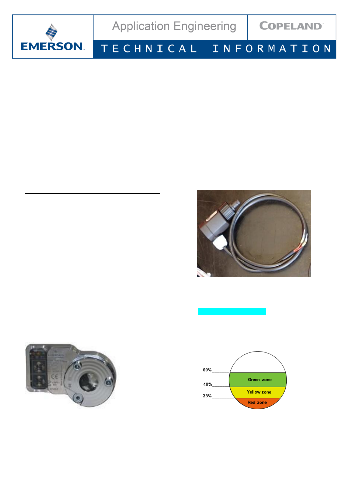
5.1.2 Oil level protection (optional)
The oil protection is achieved with an OW4/5 TraxOil watch device and OM3/4/5 TraxOil level monitoring device.
The TraxOil uses a hall sensor to measure the oil level. A magnetic float (unaffected by foaming oil) changes its
position according to the oil level. The hall sensor converts the magnetic field changes into an equivalent signal,
which is used by the integrated electronic controller to monitor and display the actual oil level with LEDs.
Figure 5: TraxOil OW5 Oil watch device Figure 6: Sight glass level control zones
Page 6
TI_Stream_NGCS_01_E_Rev02 6/18
LEDs
Status
Function
•
Oil level in green zone (60 – 40 %)
OK
• •
Oil level in green zone (60 – 40 %)
OK
•
Oil level in yellow zone (40 – 25 %)
OK
•
Oil level in red zone (25 – 0 %)
Warning or
trip
Table 3: LED code legend
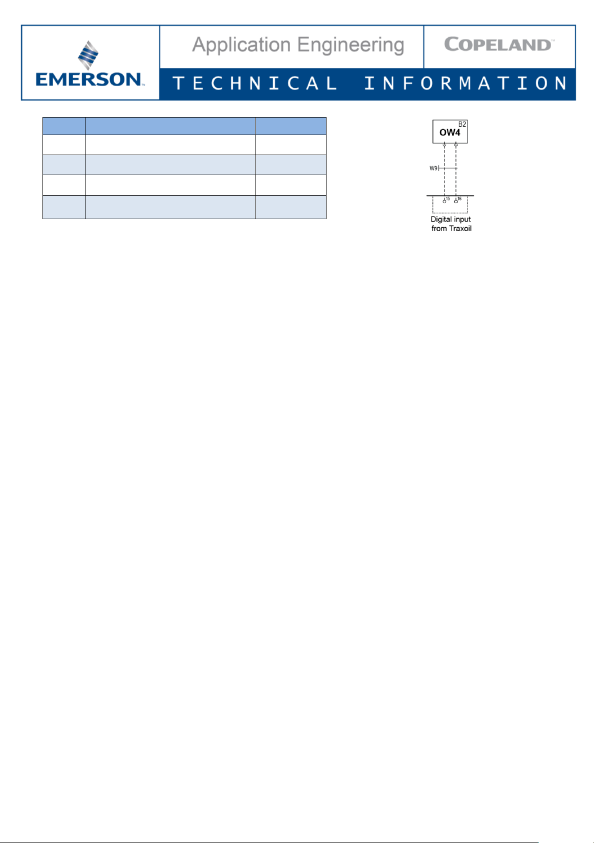
The oil watch device is not part of the standard compressor delivery; it will have to be connected to the Next Gen
CoreSense module via terminals 15 and 16.
Two connection possibilities can be chosen in the Next Gen CoreSense module app:
▪ Closed when OK:
o Default setting after activation
o Connect Blue (BU) and Black (BK) wires
▪ Open when OK:
o Connect Brown (BN) and Black (BK) wires
The user has the possibility to select between a warning or trip condition if the oil level is below 25 %.
5.2 Motor overheat protection
By using Positive Temperature Coefficient (PTC) thermistors on 4M* and 6M* Stream compressor models, Next Gen
CoreSense provides motor overheating protection.
Two chains of three thermistors each connected in series are embedded in the motor windings in such a manner that
the temperature of the thermistors can follow with little inertia.
5.2.1 Static overheat protection
The Next Gen CoreSense module will trip the compressor if the motor windings are getting too hot.
Standard condition:
▪ Total resistance of the thermistor chains @ 25 °C ≤ 1.8 kΩ
Alarm condition:
▪ Trip condition: PTC resistance > 4.5 kΩ;
▪ Reset condition: PTC resistance < 2.75 kΩ; 5 min time delay.
Trip due to sensor failure:
▪ Short circuit: PTC resistance < 20 Ω;
▪ Open circuit: PTC resistance > 20 kΩ.
5.2.2 Dynamic overheat protection
If the motor winding temperature increases in a short period (>240ohm/400ms), the module will trip the compressor.
The compressor will restart after 5 minutes.
5.3 High discharge temperature protection
Discharge temperature protection is provided using a PT1000 sensor in the compressor cylinder head.
The sensor is pre-installed at the factory and connected to the Next Gen CoreSense module. The module will protect
the compressor from high discharge temperature conditions. If the temperature sensor detects a discharge
temperature higher than 154 °C, the module will shut off the compressor until the temperature cools down to an
acceptable level (20 K below setpoint).
The configurable range of trip settings is 108 °C to 154 °C and the reset value is 83 °C to 134 °C.
▪ Trip value ≥ 154 °C for 0.5 sec
▪ Trip alarm: automatic reset after 2 minutes; discharge temp < 130 °C
Page 7

TI_Stream_NGCS_01_E_Rev02 7/18
PT1000 sensor technical data:
▪ Measuring range: -40°C to 155°C, 170°C for 30 minutes max
▪ Tightening torque: 15 Nm
▪ Protection class: IP65
Figure 7: Discharge temperature sensor
5.4 Current protection
A current sensor is located in the terminal box.
One power supply wire (2 from the same phase in case of part-winding) is going through
this sensor – see T1 in Chapter 16.2 Wiring diagrams.
The direction of the leads has to be respected.
Figure 8: Current sensor
5.4.1 Locked rotor protection
If, 2.5 seconds after compressor start, the current is 150% of the MOC value, an alarm is triggered and the
compressor trips. The alarm is reset after 5 minutes.
After 10 trips a lockout is activated and the Next Gen CoreSense module must be reset manually using the reset
button (no automatic reset).
5.4.2 MOC protection
The MOC value of a compressor is stored into the Next Gen CoreSense module. The compressor trips if the
measured current is higher than the MOC for more than 2 seconds.
This function starts 4.5 seconds after compressor start and resets automatically 5 minutes after tripping.
5.4.3 Switching frequency overstepping protection
The number of compressor starts is monitored over a defined period of time. If the compressor reaches the maximum
number of starts in a time shorter than the defined one, an alarm is triggered.
▪ Default setting is 10 starts in 1 hour and trip generation.
▪ The reset time is calculated as the difference between the defined time period (1 hour) and the actual time it
took for the defined maximum number of starts (10) to occur.
▪ Example:
o 10 starts occurred in 35 minutes
o the alarm is triggered at 35 minutes
o automatic reset will be done after 25 minutes
It is possible to choose between a warning or compressor trip.
5.4.4 MOC detection at first start
Most compressors have two sets of nominal voltages and frequencies:
▪ 50 Hz or 60 Hz value for part-winding motors (AW…)
▪ different voltages for Δ/Y start motors (EW...)
At first start and at every power reset, the Next Gen CoreSense module automatically detects the compressor power
supply (voltage and frequency) and will automatically select the corresponding MOC and undervoltage/overvoltage
protection setpoints.
If the measured voltage and/or frequency is different from the one defined on the nameplate, the module will generate
a warning.
For example, if an AWM/D (400 V / 50 Hz or 460 V / 60 Hz) motor is connected to a 230 V power line, the green LED
will flash.
Page 8

TI_Stream_NGCS_01_E_Rev02 8/18
5.5 Phase / voltage monitoring
There are 6 voltage sensor circuits to measure the 3 phases. Thanks to the 6 sensors the part-winding motors can
also be protected.
The status of each phase in direct on-line and part-winding is monitored for undervoltage, overvoltage and phase
asymmetry.
5.5.1 Missing phase protection / Phase failure protection
A comparison is made between the voltage of each phase and their average. If any of the 3 power phases is missing
after compressor start, a single-phasing condition exists.
Any voltage imbalance above 60 % is a condition for phase-loss trip.
Alarm conditions: occurs in case of missing phase conditions.
▪ Trip time: 5 minutes with automatic reset.
A missing phase can be detected during start-up and when the compressor is running.
5.5.2 Undervoltage protection
Occurs when the compressor voltage is lower than the nominal supply voltage.
Low voltage warning condition: voltage < 85 % of the nominal line voltage for 2 seconds.
Low voltage trip conditions: voltage < 75 % of the nominal line voltage 2 seconds.
▪ Trip time: 2 minutes.
5.5.3 Overvoltage protection
Occurs when the compressor voltage is higher than the nominal supply voltage.
High voltage warning condition: voltage > 115 % of the nominal line voltage for 2 seconds.
High voltage trip conditions: voltage > 125 % of the nominal line voltage for 2 seconds.
▪ Trip time: 2 minutes.
5.5.4 Voltage imbalance protection
The purpose of this feature is to protect the compressor against a voltage imbalance that could lead to motor
overheating.
A configurable setting (default = 5 %) for voltage imbalance is used to determine the operating limit of the compressor.
The voltage imbalance setting is configurable in the range of 2 to 8 % using the Next Gen CoreSense module app.
Alarm conditions:
▪ Warning: when the voltage imbalance > 3 % (configurable).
▪ Trip: when the voltage imbalance > 5 % (configurable).
▪ Reset: automatic reset after 5 min; voltage imbalance < 5 %.
5.5.5 Welded contactor protection
This protection verifies 3 independent run signals:
▪ voltage available on all terminals;
▪ current detected on 1 phase;
▪ demand signal – signal from controller to contactor.
If the three run signals are not identical, the Next Gen CoreSense module will generate an alert.
Protection is disabled in default setting. If the Next Gen CoreSense module is connected to the main controller
(terminals 17 and 18) and a demand signal is detected the feature is enabled.
The user has the possibility to select between a warning or trip condition. After a trip, the compressor will restart
after 2 minutes. Default setting is warning.
After 10 trips a lockout is activated and the module must be reset manually using the reset button (no automatic
reset).
Page 9

TI_Stream_NGCS_01_E_Rev02 9/18
5.5.6 Part-winding protection
The two winding supply cables should go through the current sensor in the same direction.
At first start or at power reset of the Next Gen CoreSense module, the voltage is measured on both windings.
▪ If the voltages are identical:
o the compressor is connected in full winding;
o the protection is disabled.
▪ If the voltages are different, the voltages are compared again after 1 second:
o if the voltage on the second winding is the same as on the first winding:
- the compressor is connected in part-winding;
- the protection is enabled;
o if the voltage on the second winding is not the same as on the first winding, the second winding is improperly
connected and the compressor trips.
The user has the possibility to select between a warning or trip condition. After a trip, the compressor will restart
after 2 minutes. Default setting is trip.
6 Variable frequency drive mode
When operating with a variable frequency drive, all electrical alarms are disabled.
The variable frequency drive (VFD) mode can be activated through the following procedure:
▪ disconnect the Next Gen CoreSense Module from the power supply;
▪ disconnect the current sensor terminals 9 and 10;
▪ connect a bridge between the current sensor terminals on the module (short circuit);
▪ energize the module:
o a short-circuit alarm (orange flashing LED) of the current sensor will appear;
▪ press and hold the reset button for more than 10 sec (can only be done during the first 5 minutes after power
reset):
o green/red quick flash code of LED;
o after 10 sec, flashing becomes slow;
▪ once the reset button is released, the VFD mode is activated.
If the current sensor is connected again, the VFD mode can be activated by pressing the reset button for more than
10 seconds.
7 Emergency mode
The emergency mode can exceptionally be used to bypass the advanced protection and operate only with basic
protection (oil pressure and motor temperature).
To activate the emergency mode:
▪ disconnect the discharge line temperature sensor from the Next Gen CoreSense module, terminals 7 and 8;
▪ connect a bridge between the discharge line temperature sensor terminals (short circuit);
▪ press and hold the reset button for more than 10 seconds.
Page 10

TI_Stream_NGCS_01_E_Rev02 10/18
8 LEDs on the terminal box cover
Status LEDs in 3 colours (green, orange and red) are visible on the top of the T-box.
Figure 9: Next Gen CoreSense module terminal box
8.1 Compressor status codes
▪ Steady green: An indication of normal operation. There are no faults or issues with the compressor.
▪ Flashing green: An indication that there is a warning condition. The compressor keeps running.
▪ Steady orange: An indication that the compressor is in emergency mode.
▪ Flashing orange: An indication that the compressor has tripped and will automatically restart after a defined
time (auto reset).
▪ Steady red: An indication that CoreSense is in parametrization mode.
▪ Flashing red: An indication that the compressor is locked out. Manual reset is needed for restart.
Reset button
Page 11

TI_Stream_NGCS_01_E_Rev02 11/18
8.2 Failure alarms displayed by LEDs
Alarms are displayed via coloured LEDs and flashing sequences. Every flash sequence is interrupted by a 2-second
pause.
Standard settings
Chap.
Flash
code
Protection feature
Standard
delivery
Compressor
keeps running
Automatic reset
Manual reset
required
Automatic reset
after trip
Warning
Trip
Lockout
5.1.1
1
Low oil pressure
(oil pump)
X
< 0.95 bar
after 4 sec
< 0.95 bar
after 2 min
5.1.2
Oil level protection
(OM)
X
Selection
possible
Oil level below
25 %
Correct oil level
5.2.1
2
Static motor overheat
protection
X
PTC resistance
> 4.5 kΩ
5 minutes and PTC
resistance < 2.75 kΩ
5.2.2
Dynamic motor
overheat protection
X
> 240 Ω/400 ms
5 minutes
5.3
3
High discharge
temperature (DLT)
X 154 °C
2 minutes and
< 130 °C
5.4.1
4
Locked rotor
protection
X 150 % of MOC
10 X Trip
5 minutes
5.4.2
Maximum Operating
Current (MOC)
X MOC
5 minutes
5.4.3
Switching frequency
protection
X
Selection
possible
10 starts/hour
When number of
starts/set time period
is lower than set value
5.4.4
MOC detection at first
start
X
Voltage different
from nameplate
5.5.1
5
Missing phase
protection
X
60 % of voltage
imbalance
5 minutes
5.5.2
Undervoltage
protection
X
< 85 % of nominal
voltage for 2 sec
< 75 % of nominal
voltage for 2 sec
2 minutes
5.5.3
Overvoltage
protection
X
> 115 % of
nominal voltage
for 2 sec
> 125 % of
nominal voltage
for 2 sec
2 minutes
5.5.4
Voltage imbalance
protection
X
Imbalance > 3 %
Imbalance > 5 %
5 minutes and min
2 % below setpoint
5.5.5
Welded contactor
protection
X
No demand
signal/current on
one phase
Selection
possible
10 X Trip
5.5.6
Part-winding
protection
X
Selection
possible
Voltage difference
after 1 sec
Table 4: Flashing explanation X = Disabled in standard delivery
9 Alarm history
The 20 most recent alarms are stored in the module memory and can be downloaded with the Next Gen CoreSense
module app.
Page 12

TI_Stream_NGCS_01_E_Rev02 12/18
10 Reset button
Pressing the reset button is needed after a compressor lockout. In addition, it can be used for an immediate trip
reset (no compressor waiting time to restart).
▪ If the tripping condition is cleared, all tripping counters are set to zero, the compressor can restart.
▪ If the tripping condition is not cleared, the reset signal is ignored.
11 Crankcase heater control
The Next Gen CoreSense module controls the crankcase heater directly, so only a crankcase heater with the same
power supply as the CoreSense module (115 VAC or 230 VAC) can be applied and connected to terminals 3 and 4.
Figure 10: Wiring diagram – Crankcase heater connections
12 Power consumption measurement
The power is calculated from the measured voltage, current and power factor.
Accuracy for each measurement:
▪ voltage ± 5 %
▪ current ± 5 %
▪ power factor ± 10 %
Power consumption in kWh is provided in the Next Gen CoreSense module app.
13 Data port for communication with Next Gen CoreSense module app
The data port can be used for communication with the Next Gen CoreSense module app to parameter or download
data (running history and alarms).
Figure 11: Data port on the Next Gen CoreSense module
Page 13

TI_Stream_NGCS_01_E_Rev02 13/18
13.1 Connectivity
There are two possibilities for communication over the data port, USB or Bluetooth gateway.
USB gateway can be used with any computer USB type-A. Adapters USB type-A to USB micro-B and USB-C are
delivered to enable connection with Android devices. The connection with iOS devices is not possible over USB
gateway.
Bluetooth gateway can be used with any device with Bluetooth adapter. It is also the only connection possibility for
iOS devices.
Figure 12: USB gateway Figure 13: Bluetooth gateway
14 Modbus module (optional)
The Next Gen CoreSense module can be equipped with a Modbus extension module for communication via RS485.
The diagnosis data can be read into system controllers using the standard Modbus RTU Protocol.
Figure 14: Modbus extension module
NOTE: More information about the Modbus interface can be found in the dedicated Technical Information
TI_Stream_NGCS_02 "Next Generation CoreSense™ – Modbus Interface Description".
15 Next Gen CoreSense module app
An application can be downloaded from Google Play Store for Android, Microsoft Store for Windows or Apple Store
for iOS devices. It provides access to the error memory/counter, so the current status of the system can be assessed,
and the operating data can be reviewed.
This application also allows to analyse the measurements done by the Next Gen CoreSense module various sensors
and to give information about compressor operation such as:
▪ operating time in normal / warning / tripping conditions;
▪ number of starts & stops;
▪ power consumption;
▪ compressor running time;
▪ crankcase heater running hours counter.
The Next Gen CoreSense module app can be connected to the Next Gen CoreSense using DP-USB gateway (not
applicable for Apple devices) or Bluetooth gateway.
Page 14

TI_Stream_NGCS_01_E_Rev02 14/18
16 Electrical connections
16.1 Basic connections
The Next Gen CoreSense module is originally delivered with the basic modules preconnected.
Figure 15: Next Gen CoreSense basic protections
16.2 Wiring diagrams
IMPORTANT
For Stream CO2 small and medium compressor models (4MTL-05 to 4MTL-30 &
4MSL-03 to 4MSL-15), the blue positions 1U, 2V, 3W, 7Z, 8X, 9Y in diagrams
below must be considered. The position of the terminals in all the other Stream
compressor models corresponds to the black positions. The factory delivery is
correct, DO NOT reverse the connections.
Legend
B1 .......... Discharge gas sensor DGT ....... Discharge gas temperature monitoring
B2 .......... Oil level watch (TraxOil) OW ........ Digital oil level watch
B3 .......... Oil differential pressure switch (OPS) OPS ....... Oil differential pressure protection
B11 ........ High-pressure switch AR ......... Alarm relay
B12 ........ Low-pressure switch DS ......... Demand signal
CTR2 ..... DP Gateway
E1 .......... Heater CH ......... Control oil heater
F1,F2,F3 Compressor fuses PTC ....... Motor thermal protection
F4, F5 .... Fan fuses PM ......... Phase monitoring
F6 .......... CoreSense and heater fuse PS .......... Power supply
F7 .......... Control circuit fuse
H1 ......... Diagnosis LED
K11 ........ Time relay for part-winding (if used)
M2 ......... Fan motor
Q11 ....... Compressor contactor Q15 ........ Fan contactor
Q12 ....... Compressor contactor Y (if Y/Δ start) Q13 ........ Compressor contactor Δ (if Y/Δ start)
Q14 ....... Compressor contactor 2nd part-winding (if used)
SB1 ....... Reset button
Y21 ........ Solenoid valve capacity control 1
Y22 ........ Solenoid valve capacity control 2
T1 .......... Current sensor CM ......... Current monitoring
Page 15

TI_Stream_NGCS_01_E_Rev02 15/18
Figure 16: Wiring diagram for part-winding motors (AW…)
Page 16

TI_Stream_NGCS_01_E_Rev02 16/18
Figure 17: Wiring diagram for Star / Delta motors (EW…)
Page 17

TI_Stream_NGCS_01_E_Rev02 17/18
Figure 18: Wiring diagram (2nd part) for part-winding and Star / Delta motors (AW… and EW…)
Page 18

TI_Stream_NGCS_01_E_Rev02 18/18
17 List of tables and figures
Tables
Table 1: Next Gen CoreSense specifications ............................................................................................................... 3
Table 2: List of basic features ....................................................................................................................................... 4
Table 3: LED code legend ............................................................................................................................................ 6
Table 4: Flashing explanation X = Disabled in standard delivery ........................................................................... 11
Figures
Figure 1: Next Generation CoreSense module ............................................................................................................ 3
Figure 2: Next Gen CoreSense inside the terminal box ............................................................................................... 3
Figure 3: Inside view of the Next Gen CoreSense module, with the modular boards .................................................. 4
Figure 4: OPS3 Oil Pressure Switch and electronic part (delivered connected) .......................................................... 5
Figure 5: TraxOil OW5 Oil watch device
Figure 6: Sight glass level control zones .................................................................................................................. 5
Figure 7: Discharge temperature sensor ...................................................................................................................... 7
Figure 8: Current sensor ............................................................................................................................................... 7
Figure 9: Next Gen CoreSense module terminal box ................................................................................................. 10
Figure 10: Wiring diagram – Crankcase heater connections ..................................................................................... 12
Figure 11: Data port on the Next Gen CoreSense module ........................................................................................ 12
Figure 12: USB gateway
Figure 13: Bluetooth gateway ..................................................................................................................................... 13
Figure 14: Modbus extension module ........................................................................................................................ 13
Figure 15: Next Gen CoreSense basic protections .................................................................................................... 14
Figure 16: Wiring diagram for part-winding motors (AW…) ....................................................................................... 15
Figure 17: Wiring diagram for Star / Delta motors (EW…) ......................................................................................... 16
Figure 18: Wiring diagram (2nd part) for part-winding and Star / Delta motors (AW… and EW…) ............................ 17
 Loading...