

Page 1

Instruction Manual
P/N 20001909, Rev. D
July 2006
ProLink® II Software
for Micro Motion®
Transmitters
Installation and Use Manual
Page 2

©2006, Micro Motion, Inc. All rights reserved. ELITE, ProLink, and the Micro Motion logo are registered trademarks of Micro
Motion, Inc., Boulder, Colorado. MVD and MVD Direct Connect are trademarks of Micro Motion., Inc., Boulder, Colorado. Micro
Motion is a registered trade name of Micro Motion, Inc., Boulder, Colorado. The Emerson logo is a trademark of Emerson Electric
Co. All other trademarks are property of their respective owners.
Page 3

Contents
Chapter 1 Before You Begin . . . . . . . . . . . . . . . . . . . . . . . . . . . . . . . . . . . . . 1
1.1 About this manual . . . . . . . . . . . . . . . . . . . . . . . . . . . . . . . . . . . . . . . . . . . . . . . . . . . . 1
1.2 About ProLink II software . . . . . . . . . . . . . . . . . . . . . . . . . . . . . . . . . . . . . . . . . . . . . . 1
1.2.1 Supported transmitters . . . . . . . . . . . . . . . . . . . . . . . . . . . . . . . . . . . . . . . 1
1.2.2 Uses of ProLink II. . . . . . . . . . . . . . . . . . . . . . . . . . . . . . . . . . . . . . . . . . . . 2
1.3 ProLink II requirements . . . . . . . . . . . . . . . . . . . . . . . . . . . . . . . . . . . . . . . . . . . . . . . . 2
1.3.1 PC requirements . . . . . . . . . . . . . . . . . . . . . . . . . . . . . . . . . . . . . . . . . . . . 2
1.3.2 Installation kits . . . . . . . . . . . . . . . . . . . . . . . . . . . . . . . . . . . . . . . . . . . . . . 2
1.4 Determining your transmitter type. . . . . . . . . . . . . . . . . . . . . . . . . . . . . . . . . . . . . . . . 3
1.5 Micro Motion customer service . . . . . . . . . . . . . . . . . . . . . . . . . . . . . . . . . . . . . . . . . . 3
Chapter 2 Installation and Setup . . . . . . . . . . . . . . . . . . . . . . . . . . . . . . . . . . 7
2.1 Overview . . . . . . . . . . . . . . . . . . . . . . . . . . . . . . . . . . . . . . . . . . . . . . . . . . . . . . . . . . . 7
2.2 Installation and setup . . . . . . . . . . . . . . . . . . . . . . . . . . . . . . . . . . . . . . . . . . . . . . . . . 7
2.2.1 Ensure required privileges . . . . . . . . . . . . . . . . . . . . . . . . . . . . . . . . . . . . . 7
2.2.2 Install the ProLink II software. . . . . . . . . . . . . . . . . . . . . . . . . . . . . . . . . . . 8
2.2.3 Generate the temporary license. . . . . . . . . . . . . . . . . . . . . . . . . . . . . . . . . 8
2.2.4 Determine your connection type . . . . . . . . . . . . . . . . . . . . . . . . . . . . . . . . 9
2.2.5 Install the signal converter and connect the wires . . . . . . . . . . . . . . . . . . 11
2.2.6 Configure ProLink II connection parameters and connect to the
transmitter . . . . . . . . . . . . . . . . . . . . . . . . . . . . . . . . . . . . . . . . . . . . . . . . 26
2.2.7 Obtain and configure a site key . . . . . . . . . . . . . . . . . . . . . . . . . . . . . . . . 29
2.3 Troubleshooting the ProLink II installation. . . . . . . . . . . . . . . . . . . . . . . . . . . . . . . . . 30
2.3.1 Insufficient privileges . . . . . . . . . . . . . . . . . . . . . . . . . . . . . . . . . . . . . . . . 30
2.3.2 Missing or corrupt registry entries . . . . . . . . . . . . . . . . . . . . . . . . . . . . . . 30
2.4 Troubleshooting the ProLink II connection . . . . . . . . . . . . . . . . . . . . . . . . . . . . . . . . 31
2.4.1 OPC server or OPC client issues. . . . . . . . . . . . . . . . . . . . . . . . . . . . . . . 31
2.4.2 Other issues. . . . . . . . . . . . . . . . . . . . . . . . . . . . . . . . . . . . . . . . . . . . . . . 31
Installation and Use Manual i
Page 4

Contents
Chapter 3 Using ProLink II Software . . . . . . . . . . . . . . . . . . . . . . . . . . . . . . 33
3.1 Overview . . . . . . . . . . . . . . . . . . . . . . . . . . . . . . . . . . . . . . . . . . . . . . . . . . . . . . . . . . 33
3.2 ProLink II user interface . . . . . . . . . . . . . . . . . . . . . . . . . . . . . . . . . . . . . . . . . . . . . . 33
3.3 Startup . . . . . . . . . . . . . . . . . . . . . . . . . . . . . . . . . . . . . . . . . . . . . . . . . . . . . . . . . . . 33
3.3.1 Connecting to a transmitter . . . . . . . . . . . . . . . . . . . . . . . . . . . . . . . . . . . 34
3.3.2 Disconnecting . . . . . . . . . . . . . . . . . . . . . . . . . . . . . . . . . . . . . . . . . . . . . 36
3.4 ProLink II help system. . . . . . . . . . . . . . . . . . . . . . . . . . . . . . . . . . . . . . . . . . . . . . . . 36
3.5 Viewing installed options. . . . . . . . . . . . . . . . . . . . . . . . . . . . . . . . . . . . . . . . . . . . . . 36
3.6 Viewing process data . . . . . . . . . . . . . . . . . . . . . . . . . . . . . . . . . . . . . . . . . . . . . . . . 37
3.7 Viewing and resetting totalizers and inventories . . . . . . . . . . . . . . . . . . . . . . . . . . . . 37
3.8 Viewing meter status. . . . . . . . . . . . . . . . . . . . . . . . . . . . . . . . . . . . . . . . . . . . . . . . . 38
3.9 Viewing and acknowledging alarms . . . . . . . . . . . . . . . . . . . . . . . . . . . . . . . . . . . . . 39
3.9.1 Viewing alarms . . . . . . . . . . . . . . . . . . . . . . . . . . . . . . . . . . . . . . . . . . . . 39
3.9.2 Acknowledging alarms . . . . . . . . . . . . . . . . . . . . . . . . . . . . . . . . . . . . . . . 41
3.10 Managing the ProLink II license . . . . . . . . . . . . . . . . . . . . . . . . . . . . . . . . . . . . . . . . 41
3.10.1 Transferring to same PC . . . . . . . . . . . . . . . . . . . . . . . . . . . . . . . . . . . . . 41
3.10.2 Transferring to different PC . . . . . . . . . . . . . . . . . . . . . . . . . . . . . . . . . . . 41
Chapter 4 Initial Transmitter Startup Procedures. . . . . . . . . . . . . . . . . . . . . . 43
4.1 Overview . . . . . . . . . . . . . . . . . . . . . . . . . . . . . . . . . . . . . . . . . . . . . . . . . . . . . . . . . . 43
4.2 Loop tests . . . . . . . . . . . . . . . . . . . . . . . . . . . . . . . . . . . . . . . . . . . . . . . . . . . . . . . . . 43
4.3 Trimming the milliamp (mA) output(s) . . . . . . . . . . . . . . . . . . . . . . . . . . . . . . . . . . . . 46
4.4 Zeroing the meter . . . . . . . . . . . . . . . . . . . . . . . . . . . . . . . . . . . . . . . . . . . . . . . . . . . 48
Chapter 5 Transmitter Configuration, Characterization,
and Calibration . . . . . . . . . . . . . . . . . . . . . . . . . . . . . . . . . . . . . 51
5.1 Overview . . . . . . . . . . . . . . . . . . . . . . . . . . . . . . . . . . . . . . . . . . . . . . . . . . . . . . . . . . 51
5.2 Using configuration files . . . . . . . . . . . . . . . . . . . . . . . . . . . . . . . . . . . . . . . . . . . . . . 51
5.2.1 Saving a configuration file to a PC. . . . . . . . . . . . . . . . . . . . . . . . . . . . . . 51
5.2.2 Loading a configuration file to a transmitter. . . . . . . . . . . . . . . . . . . . . . . 52
5.3 Configuring a transmitter. . . . . . . . . . . . . . . . . . . . . . . . . . . . . . . . . . . . . . . . . . . . . . 52
5.3.1 Using the Gas Unit Configurator tool. . . . . . . . . . . . . . . . . . . . . . . . . . . . 54
5.4 Characterizing the meter. . . . . . . . . . . . . . . . . . . . . . . . . . . . . . . . . . . . . . . . . . . . . . 55
5.4.1 When to characterize. . . . . . . . . . . . . . . . . . . . . . . . . . . . . . . . . . . . . . . . 55
5.4.2 Characterization parameters . . . . . . . . . . . . . . . . . . . . . . . . . . . . . . . . . . 55
5.4.3 How to characterize . . . . . . . . . . . . . . . . . . . . . . . . . . . . . . . . . . . . . . . . . 58
5.5 Calibrating the meter. . . . . . . . . . . . . . . . . . . . . . . . . . . . . . . . . . . . . . . . . . . . . . . . . 58
5.5.1 When to calibrate. . . . . . . . . . . . . . . . . . . . . . . . . . . . . . . . . . . . . . . . . . . 59
5.5.2 Density calibration . . . . . . . . . . . . . . . . . . . . . . . . . . . . . . . . . . . . . . . . . . 59
5.5.3 Temperature calibration . . . . . . . . . . . . . . . . . . . . . . . . . . . . . . . . . . . . . . 63
5.6 Compensating for pressure. . . . . . . . . . . . . . . . . . . . . . . . . . . . . . . . . . . . . . . . . . . . 64
5.6.1 Options . . . . . . . . . . . . . . . . . . . . . . . . . . . . . . . . . . . . . . . . . . . . . . . . . . 64
5.6.2 Pressure correction factors . . . . . . . . . . . . . . . . . . . . . . . . . . . . . . . . . . . 64
5.6.3 Configuration . . . . . . . . . . . . . . . . . . . . . . . . . . . . . . . . . . . . . . . . . . . . . . 64
5.7 Compensating for temperature . . . . . . . . . . . . . . . . . . . . . . . . . . . . . . . . . . . . . . . . . 65
5.8 Configuring polling . . . . . . . . . . . . . . . . . . . . . . . . . . . . . . . . . . . . . . . . . . . . . . . . . . 66
ii ProLink® II Software for Micro Motion® Transmitters
Page 5

Contents
Chapter 6 Meter Verification . . . . . . . . . . . . . . . . . . . . . . . . . . . . . . . . . . . 67
6.1 Overview . . . . . . . . . . . . . . . . . . . . . . . . . . . . . . . . . . . . . . . . . . . . . . . . . . . . . . . . . . 67
6.2 Running the meter verification test . . . . . . . . . . . . . . . . . . . . . . . . . . . . . . . . . . . . . . 67
6.2.1 First panel: Sensor and Transmitter Configuration. . . . . . . . . . . . . . . . . . 67
6.2.2 Second panel: Test Definition . . . . . . . . . . . . . . . . . . . . . . . . . . . . . . . . . 69
6.2.3 Third panel: Start . . . . . . . . . . . . . . . . . . . . . . . . . . . . . . . . . . . . . . . . . . . 70
6.2.4 Fourth panel: Test Results . . . . . . . . . . . . . . . . . . . . . . . . . . . . . . . . . . . . 73
6.2.5 Fifth panel: Report . . . . . . . . . . . . . . . . . . . . . . . . . . . . . . . . . . . . . . . . . . 74
Chapter 7 Data Logger. . . . . . . . . . . . . . . . . . . . . . . . . . . . . . . . . . . . . . . . 77
7.1 Overview . . . . . . . . . . . . . . . . . . . . . . . . . . . . . . . . . . . . . . . . . . . . . . . . . . . . . . . . . . 77
7.2 Using Data Logger . . . . . . . . . . . . . . . . . . . . . . . . . . . . . . . . . . . . . . . . . . . . . . . . . . 77
7.2.1 Defining the log file . . . . . . . . . . . . . . . . . . . . . . . . . . . . . . . . . . . . . . . . . 77
7.2.2 Specifying log contents . . . . . . . . . . . . . . . . . . . . . . . . . . . . . . . . . . . . . . 78
7.2.3 Starting and stopping the logging function. . . . . . . . . . . . . . . . . . . . . . . . 79
7.2.4 Data Logger tools. . . . . . . . . . . . . . . . . . . . . . . . . . . . . . . . . . . . . . . . . . . 79
Appendix A Transmitter Terminal Reference . . . . . . . . . . . . . . . . . . . . . . . . . . 81
A.1 Overview . . . . . . . . . . . . . . . . . . . . . . . . . . . . . . . . . . . . . . . . . . . . . . . . . . . . . . . . . . 81
A.2 Transmitter terminal diagrams . . . . . . . . . . . . . . . . . . . . . . . . . . . . . . . . . . . . . . . . . . 82
Appendix B Configuring the Discrete Batch Application . . . . . . . . . . . . . . . . . . 87
B.1 About this appendix. . . . . . . . . . . . . . . . . . . . . . . . . . . . . . . . . . . . . . . . . . . . . . . . . . 87
B.2 About discrete batching. . . . . . . . . . . . . . . . . . . . . . . . . . . . . . . . . . . . . . . . . . . . . . . 87
B.3 Discrete batch configuration . . . . . . . . . . . . . . . . . . . . . . . . . . . . . . . . . . . . . . . . . . . 87
B.3.1 Flow source . . . . . . . . . . . . . . . . . . . . . . . . . . . . . . . . . . . . . . . . . . . . . . . 89
B.3.2 Control options. . . . . . . . . . . . . . . . . . . . . . . . . . . . . . . . . . . . . . . . . . . . . 90
B.3.3 Configure presets. . . . . . . . . . . . . . . . . . . . . . . . . . . . . . . . . . . . . . . . . . . 92
B.3.4 Batch control methods . . . . . . . . . . . . . . . . . . . . . . . . . . . . . . . . . . . . . . . 94
B.4 Running a batch . . . . . . . . . . . . . . . . . . . . . . . . . . . . . . . . . . . . . . . . . . . . . . . . . . . . 97
B.5 Performing Batch AOC calibration. . . . . . . . . . . . . . . . . . . . . . . . . . . . . . . . . . . . . . . 98
Index . . . . . . . . . . . . . . . . . . . . . . . . . . . . . . . . . . . . . . . . . . . . . . . . . . . . . 99
Installation and Use Manual iii
Page 6

iv ProLink® II Software for Micro Motion® Transmitters
Page 7

Chapter 1
Before You Begin
1.1 About this manual
This manual explains how to install the Micro Motion
on your personal computer (PC).
This manual also provides an overview of using ProLink II with Micro Motion transmitters. Before
using this instruction manual, the reader should be familiar with the Microsoft Windows operating
system.
There are a number of transmitter and application features that may appear in your ProLink II
installation: for example, the enhanced density application, the petroleum measurement application,
the custody transfer application, event configuration, or display configuration. This manual contains
information on configuring and using the discrete batch application (see Appendix B). For detailed
information on configuring and using other transmitter-specific or application-specific features, see
the appropriate transmitter or application manual. If you still have questions, contact the Micro
Motion Customer Service Department. Telephone numbers are listed in Section 1.5.
®
ProLink®II software program, v2.5 and later,
ProLink II Setup Transmitter StartupUsing ProLink IIBefore You Begin
1.2 About ProLink II software
This section provides an overview of ProLink II software.
1.2.1 Supported transmitters
The ProLink II program provides communication between a personal computer and the following
Micro Motion transmitters and devices:
• Model 1700/2700
• Model 1500/2500
• Model 2400S
• Core processor and Enhanced core processor
•MVD
• Series 3000 with 4-wire sensor interface (MVD™)
• RFT9739
• RFT9712
• IFT9701/9703
Note: MVD Direct Connect is a direct host meter that does not include a transmitter. However,
ProLink II can be used to communicate with the core processor component in MVD Direct Connect
installations.
™
Direct Connect
™
Installation and Use Manual 1
Page 8

Before You Begin
1.2.2 Uses of ProLink II
Using ProLink II, you can:
• Perform initial transmitter startup procedures
• Read process variables
• Manage totalizers and inventories
• Configure the transmitter
• Perform verification and calibration procedures
• Read meter status information and alarm conditions
• Troubleshoot the meter
1.3 ProLink II requirements
Before starting the ProLink II installation, review the requirements in this section.
1.3.1 PC requirements
To install and run ProLink II, your PC must meet or exceed the following requirements:
• 200 MHz Pentium processor
• One of the following:
- Windows 98 (initial release or second edition) with 32 megabytes (MB) RAM
- Windows ME with 64 MB RAM
- Windows NT 4.0 with Service Pack 6a and 64 MB RAM
- Windows 2000 with Service Pack 3 and 128 MB RAM
- Windows XP with Service Pack 1 and 128 MB RAM
• 24 MB of available hard disk space
• Video with support for 256 or more colors
• An available serial port or USB port
Note: Windows NT does not support the USB port.
1.3.2 Installation kits
Micro Motion provides ProLink II installation kits for RS-485 connections (serial port or USB) and
for Bell 202 connections (serial port or USB). Kit contents are listed in Table 1-1. If you need a
ProLink II installation kit, contact Micro Motion.
2 ProLink® II Software for Micro Motion® Transmitters
Page 9

Before You Begin
Tabl e 1-1 ProLink II installation kits
Physical layer Connection Kit contents
RS-485 Serial port • Black Box Async RS-232 <-> 2-wire RS-485 Interface Converter
(Code IC521A-F)
• DB9-DB25 adapter
• DB9-DB9 tester
•Cable
USB • Black Box Async RS-232 <-> 2-wire RS-485 Interface Converter
(Code IC521A-F)
• Black Box USB-to-serial (RS-232) converter (Code IC138A)
• DB9-DB25 adapter
• DB9-DB9 tester
•Cable
Bell 202 Serial port • MACTek VIATOR RS232 HART Interface with integral HART cable
terminating in two clips (Model 010001)
• DB9-DB9 tester
USB • MACTek VIATOR USB HART Interface with integral USB cable and
integral HART cable terminating in two clips (Model 010031)
Note: If you use a different RS-232 to RS-485 signal converter or HART interface, it is your
responsibility to ensure that your equipment provides equivalent functionality. See the ReadMe.txt file
in the ProLink II installation directory, or contact Micro Motion customer support for assistance or
additional information.
ProLink II Setup Transmitter StartupUsing ProLink IIBefore You Begin
Note: A Windows driver is required for correct operation of the VIATOR USB HART Interface. This
driver is provided with the VIATOR USB HART Interface. Ensure that the driver is installed before
attempting to connect through the USB port. If this driver is not installed, Windows will not recognize
the USB converter when it is plugged into the USB port.
1.4 Determining your transmitter type
To configure, use, and troubleshoot the transmitter, you must know your transmitter type,
installation/mounting type, and outputs option board type (Series 1000/2000 transmitters only). The
transmitter’s model number, which is provided on a tag attached to the transmitter, provides this
information. See Figure 1-1 for assistance in interpreting the model number.
If you are using MVD Direct Connect, refer to the model number on the sensor.
1.5 Micro Motion customer service
For customer service, phone the support center nearest you:
• In the U.S.A., phone 1-800-522-MASS (1-800-522-6277)
• In Canada and Latin America, phone (303) 527-5200
• In Asia, phone (65) 6770-8155
• In the U.K., phone 0870 240 1978 (toll-free)
• Outside the U.K., phone +31 (0) 318 495 670
Installation and Use Manual 3
Page 10

Before You Begin
Figure 1-1 Transmitter model numbers and codes
RFT9739
R F T 9 7 3 9 x x x x x x x
Mounting:
• R = rack-mount or panel-mount
• D, E = field-mount
Transmitter model
Series 3000
3 x x 0 x x x x x x x x x x x x
Sensor interface:
• 0 = none (MVD)
• 5, 6 = 4-wire (MVD)
Mounting:
• R = rack-mount
• P = panel-mount
• A = field-mount
Transmitter model
Model 1500/2500
x 5 0 0 x x x x x x x x x x x x
RFT9712
R F T 9 7 1 2 x x x x x x x
Transmitter model
IFT9701/9703
I F T 9 7 0 x x x x x x x x
Mounting:
•I, M = integral
• R, L, J, S, A = remote
Transmitter model
Model 1700/2700
x 7 0 0 x x x x x x x x x x
Software option 1:
• B = Filling and Dosing application
(1)
Outputs option board:
• A = analog outputs option board
• B, C = configurable input/outputs option board
Mounting/installation type:
• D = 4-wire to sensor with integral core processor
• B = remote core processor with remote transmitter
Transmitter model
(1) Model 1500 transmitter with filling and dosing application only.
Requires Outputs option board C.
Outputs option board:
• A = analog outputs option board
• B, C = configurable input/outputs option board
• D = intrinsically safe outputs option board
•E = F
OUNDATION fieldbus outputs option board
• G = PROFIBUS PA outputs option board
Mounting/installation type:
• R = remote (4-wire remote installation)
• I = integral (transmitter mounted on sensor)
• C = transmitter/core processor assembly (9-wire remote installation)
• B = remote core processor with remote transmitter
Transmitter model
4 ProLink® II Software for Micro Motion® Transmitters
Page 11

Before You Begin
Figure 1-1 Transmitter model numbers and codes continued
Model 2400S
2 4 0 0 S x x x x x x x x x
User interface option:
• 1 = display/LCD with glass lens
• 2 = no display/LCD
• 3 = display/LCD with non-glass lens
Outputs option board:
• A = analog outputs option board
• C = DeviceNet I/O option board
• D = PROFIBUS DP I/O option board
Transmitter model
ProLink II Setup Transmitter StartupUsing ProLink IIBefore You Begin
Installation and Use Manual 5
Page 12

6 ProLink® II Software for Micro Motion® Transmitters
Page 13

Chapter 2
Installation and Setup
2.1 Overview
This chapter provides information on installing ProLink II software, connecting to the transmitter, and
troubleshooting the installation or connection.
To install and set up ProLink II, the following steps are required:
1. Ensure required privileges (see Section 2.2.1)
2. Install the ProLink II software onto your PC (see Section 2.2.2)
3. Generate the temporary license (see Section 2.2.3)
4. Determine your connection type (see Section 2.2.4)
5. Install the signal converter and connect the wires between the PC and the transmitter (see
Section 2.2.5)
6. Configure the connection and connect to the transmitter (see Section 2.2.6)
7. Obtain and configure a site key (see Section 2.2.7)
For troubleshooting information, see Section 2.3 and Section 2.4.
ProLink II Setup Transmitter StartupUsing ProLink IIBefore You Begin
2.2 Installation and setup
To install and set up ProLink II, follow the steps below.
2.2.1 Ensure required privileges
Installing and running ProLink II requires specific privileges. Install ProLink II using the required
user account, and ensure that all persons who will run ProLink II have the required privileges. See
Tabl e 2 -1 .
Tabl e 2-1 Required privileges
Operating system To install ProLink II To run ProLink II
Windows NT 4.0 Must be the built-in Admin account • Read/write local hard drive
Windows 2000 Must be member of the Administrators
Windows XP Must be member of the Administrators
Windows 98 Not applicable Not applicable
Windows ME Not applicable Not applicable
group
group
• Read/write Windows registry
• Read/write local hard drive
• Read/write Windows registry
• Read/write local hard drive
• Read/write Windows registry
Installation and Use Manual 7
Page 14

Installation and Setup
During installation on a Windows NT, Windows 2000, or Windows XP system, if the installer is not in
the Administrator group, the installation wizard may display a message warning that the installation
may not be successful. If this occurs, the installation wizard will run to completion but the Windows
registry may not be updated correctly. If you are subsequently unable to connect to a transmitter,
reinstall the software using the required user account.
2.2.2 Install the ProLink II software
To install ProLink II software:
1. Insert the ProLink II CD-ROM into the PC’s CD-ROM drive.
2. If the setup program does not start automatically, locate and run the SETUP.EXE file. The file
is located in the root directory on the CD-ROM (e.g., D:\setup.exe, where “D” is your
CD-ROM drive letter).
3. Follow the on-screen instructions to complete the installation. If you have a previous version
of ProLink II installed on your PC, you may be prompted to remove it before installing the
new version.
Note: The ProLink II site key is associated with a disk drive and specific folder on your PC. If you
decide to move ProLink II after installation, you will have to transfer the license and reinstall
ProLink II. To avoid this step, be sure to install ProLink II into a location that you can use
permanently.
Note: If you have a Model 2700 transmitter with transmitter software earlier than v3.4, and you have
the enhanced density application installed, you cannot access the enhanced density functions with
ProLink II v2.1 or later. To configure and manage the enhanced density application from ProLink II,
you must either upgrade your transmitter software to v3.4 or later, or continue to use ProLink II v1.x
with enhanced density support. You can install both ProLink II v1.x and ProLink II v2.0 or later on
the same PC, and you can use ProLink II v2.0 or later with your pre–v3.4 transmitter for all functions
except enhanced density. You can also use ProLink v1.2 with transmitter software v3.4 and later;
however, not all transmitter functions will be accessible using the older program.
2.2.3 Generate the temporary license
The first time ProLink II is run, you will be prompted to generate a temporary license. This license
will allow you to run ProLink II with full functionality for seven days, starting from the current date
and time. Follow the on-screen instructions to generate the temporary license.
Note: If you are running Windows 98 or Windows ME, you must temporarily disable any anti-virus
software running on your PC before you can generate the temporary license. You can re-enable the
anti-virus software immediately after the temporary license has been successfully generated.
Continue with Section 2.2.4 to use ProLink II for seven days. During this time period, follow the
instructions in Section 2.2.7 to obtain and configure a site key.
Note: If you attempt to use ProLink II after the temporary license has expired, ProLink II will no
longer allow you to connect to a transmitter.
8 ProLink® II Software for Micro Motion® Transmitters
Page 15

Installation and Setup
2.2.4 Determine your connection type
Different transmitters and networks support different connection types.
• Table 2-2 lists the supported protocols and wiring methods for IFT97xx and RFT97xx
transmitters.
• Table 2-3 lists the supported protocols and wiring methods for Model 1500/2500,
Model 1700/2700, and Series 3000 transmitters.
• Table 2-4 lists the supported protocols and wiring methods for the Model 2400S transmitter.
• Table 2-5 lists the supported protocols and wiring methods for all MVD Direct Connect
systems.
In these tables, and throughout the chapter:
• Temporary – refers to a connection that is not permanent and is typically used only for
configuration and troubleshooting. Because the transmitter housing must be open for the
duration of the connection, these connections should be removed and the housing closed as
soon as possible. The operator should be aware of the safety hazards that result from opening
the transmitter housing.
• Hard-wired – refers to a connection that is made to the permanent wiring, usually a transmitter
output wire or the network that the transmitter is already using. Because hard-wired
connections do not require the transmitter housing to be open, they can be left in place as
desired.
ProLink II Setup Transmitter StartupUsing ProLink IIBefore You Begin
• AN – refers to transmitters with the analog outputs option board
• IS – refers to transmitters with the intrinsically safe outputs option board
• CIO – refers to transmitters with the configurable input/outputs option board
• FF – refers to transmitters with the F
OUNDATION fieldbus input/output option board
• PA – refers to transmitters with the PROFIBUS-PA input/output option board
• DP – refers to transmitters with the PROFIBUS-DP input/output option board
• DN – refers to transmitters with the DeviceNet input/output option board
• MVD Direct Connect – refers to meter installations that include the core processor but do not
include a transmitter. ProLink II is connected directly to the RS-485 terminals on the core
processor or the MVD Direct Connect I.S. barrier.
Once you have determined your connection type, use the Wiring Method # value in the table to direct
you to the correct wiring procedure in Section 2.2.5.
Installation and Use Manual 9
Page 16

Installation and Setup
Tabl e 2-2 Communication protocols and wiring methods for IFT97xx and RFT97xx transmitters
Transmitter type
Wiring method
IFT9701
IFT9703 RFT9712 RFT9739
Wiring
method #
HART protocol
Bell 202 physical layer
• Temporary or hard-wired connection to transmitter or
multidrop network
• Temporary connection to field-mount transmitters ✓✓ 2
• Temporary connection to rack-mount transmitters ✓ 3
RS-485 physical layer
• Temporary or hard-wired connection to transmitter or
multidrop network
✓✓✓ 1
✓✓ 5
Modbus protocol (RS-485 physical layer)
• Temporary or hard-wired connection to transmitter or
multidrop network
✓ 6
Tabl e 2-3 Communication protocols and wiring methods for Model 1500/2500, Model 1700/2700, and
Series 3000 transmitters
Transmitter type
Wiring method
Model
1500/2500
Model
1700/2700
Series
3000
Wiring
method #
HART protocol
RS-485 physical layer
• Temporary or hard-wired connection to RS-485
terminals
Bell 202 physical layer
• Temporary or hard-wired connection to primary mA
output or multidrop network
• Temporary or hard-wired connection to primary mA
output or multidrop network
(1)
✓
AN ✓ 5
AN
CIO
IS 4
✓ 1
Modbus protocol (RS-485 physical layer)
• Temporary or hard-wired connection to RS-485
terminals
• Temporary connection to service port ✓✓✓ 7
(1) Except Model 1500 transmitter with the Filling and Dosing application. The Model 1500 transmitter with the Filling and Dosing
application does not support HART communication.
✓ AN ✓ 6
10 ProLink® II Software for Micro Motion® Transmitters
Page 17

Installation and Setup
Tabl e 2-4 Communication protocols and wiring methods for Model 2400S transmitters
Wiring method Transmitter type Wiring method #
HART protocol
• Temporary connection to HART clips AN 8
• Temporary or hard-wired connection to primary mA output or
multidrop network
(Bell 202 physical layer)
AN 1
Modbus protocol (RS-485 physical layer)
• Temporary connection to service port clips AN
DN
DP
7
Tabl e 2-5 Communication protocols and wiring methods for MVD Direct Connect
Wiring method Wiring method #
Modbus protocol
• Temporary or hard-wired connection to RS-485 terminals on core processor or I.S.
barrier
(RS-485 physical layer)
9
2.2.5 Install the signal converter and connect the wires
All ProLink II connection methods require a signal converter. Micro Motion offers four different
installation kits to cover all required signal converter types. See Section 1.3.2 for a list of the available
installation kits and signal converters.
ProLink II Setup Transmitter StartupUsing ProLink IIBefore You Begin
Note: A Windows driver is required for correct operation of the VIATOR USB HART Interface. This
driver is provided with the VIATOR USB HART Interface. Ensure that the driver is installed before
attempting to connect through the USB port. If this driver is not installed, Windows will not recognize
the USB converter when it is plugged into the USB port.
To install the signal converter and connect the wires, follow the instructions for your connection type.
Refer to the Wiring Method # value in Table 2-2, 2-3, 2-4 or 2-5.
WARNING
On Model 1700/2700 transmitters, opening the power supply compartment in
explosive atmospheres while the power is on can cause an explosion.
Before using the service port to communicate with the transmitter in a hazardous
area, make sure the atmosphere is free of explosive gases.
WARNING
On Model 1700/2700 transmitters, opening the power supply compartment
can expose the operator to electric shock.
To avoid the risk of electric shock, do not touch the power supply wires or terminals
while using the service port.
Installation and Use Manual 11
Page 18

Installation and Setup
On Model 3350/3700 transmitters, opening the wiring compartment in
explosive atmospheres can cause an explosion.
Do not remove the compartment covers in an explosive atmosphere within three
minutes after power is disconnected.
On Model 2400S transmitters, removing the transmitter housing cover in a
hazardous area can cause an explosion.
Because the housing cover must be removed to connect to this transmitter using
the service port clips or HART clips, these connections should be used only for
temporary connections, for example, for configuration or troubleshooting purposes.
When the transmitter is in an explosive atmosphere, use a different method to
connect to your transmitter.
WARNING
WARNING
WARNING
Removing the core processor lid can expose the operator to electric shock.
To avoid the risk of electric shock, do not touch the power supply wires or terminals
while removing or replacing the core processor lid, or while using the RS-485
terminals.
CAUTION
Connecting a HART device to the transmitter’s primary mA output could
cause transmitter output error.
If the primary mA output is being used for flow control, connecting the VIATOR
HART Interface to the output loop, via either the mA terminals or the HART clips,
could cause the transmitter’s 4–20 mA output to change, which would affect flow
control devices.
Set control devices for manual operation before connecting the VIATOR HART
Interface to the transmitter’s primary mA output loop.
12 ProLink® II Software for Micro Motion® Transmitters
Page 19
Installation and Setup
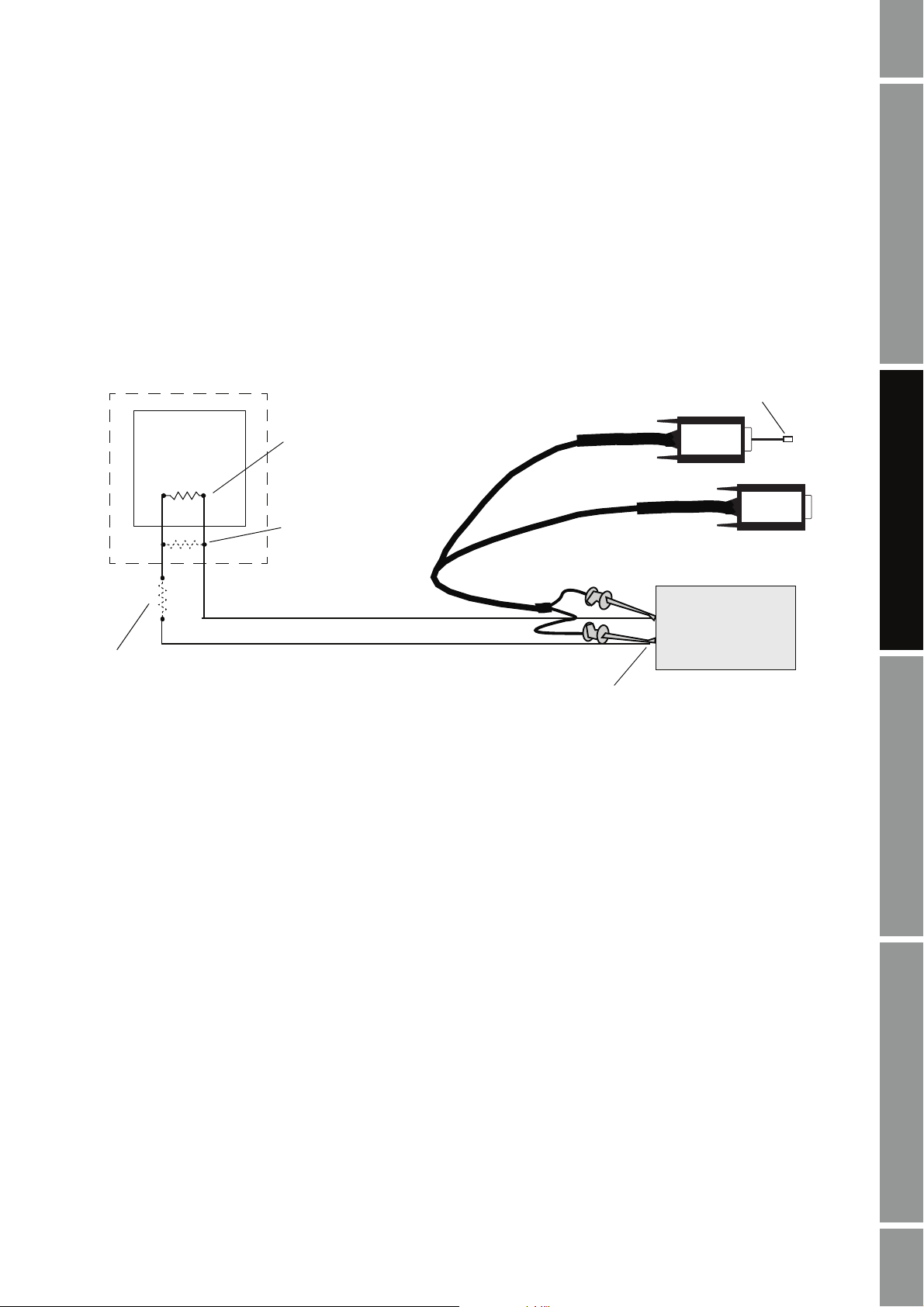
Method 1: HART/Bell 202 temporary or hard-wired connection to transmitter or multidrop network
Note: This method is supported by RFT9739, RFT9712, and IFT9701/9703 transmitters, by Model
1700/2700 transmitters with the analog outputs option board or configurable input/outputs options
board, by Model 1500/2500 transmitters, by Model 2400S transmitters with the analog outputs option
board, and by Series 3000 transmitters.
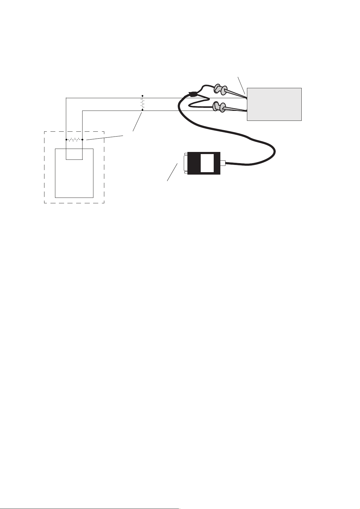
Using a VIATOR HART Interface, the PC can be connected directly to a transmitter’s primary mA
output terminals, to the output wires from these terminals, or to any point in a multidrop network that
is wired to these terminals. Figure 2-1 shows the wiring for this connection type.
Figure 2-1 HART/Bell 202 temporary or permanent connection to transmitter or multidrop network
USB plug
R1
See Step 3
DCS or
PLC
R2
See Step 3
or
R3
See Step 3
Primary mA output terminals
VIATOR
VIATOR
Tr an s m it t er
1. At the PC, connect the VIATOR HART Interface to the PC’s serial or USB port.
2. Attach the VIATOR HART Interface leads:
• To any point on the network (hard-wired connection)
• Directly to the primary mA output terminals on your transmitter (temporary connection).
See Table 2-6
• To the output wires from the primary mA output terminals on your transmitter (hard-wired
connection). See Table 2-6
The connection is polarity-insensitive; you can attach either lead to either terminal. For
assistance in identifying the primary mA output terminals, see Appendix A.
ProLink II Setup Transmitter StartupUsing ProLink IIBefore You Begin
Installation and Use Manual 13
Page 20

Installation and Setup
Tabl e 2-6 Primary mA output terminals – Method 1
Termi na ls
Transmitter
RFT9712 17 16
RFT9739 rack-mount Z30 D30
RFT9739 field-mount 17 18
IFT9701/9703 4–20 mA 4–20 mA
Model 1500/2500 21 22
Model 1700/2700 AN
Model 1700/2700 CIO
Model 2400S AN
Series 3000 panel-mount with screw-type connectors c2 a2
Series 3000 panel-mount with I/O cables 14 15
Series 3000 rack-mount c2 a2
Series 3000 field-mount 2 1
PV + PV –
12
3. If necessary, add a resistor to the connection as required by your transmitter (see Table 2-7).
- If no other device is connected to the primary mA output, add the resistor in parallel with
the primary mA output.
- If the primary mA output is connected to a remote device such as a DCS or a PLC with an
internal resistor (R2), ensure its value is within the range described in Table 2-7. If it is
lower than 250 Ω, add resistor R1 to the connection so that the overall resistance (R1 + R2)
is within the range described in Table 2-7.
- If your DCS or PLC does not have an internal resistor, add resistor R3 and make sure its
value is within the range described in Table 2-7
.
Tabl e 2-7 Resistance requirements for HART/Bell 202 connection
Transmitter Resistance
Model 1500/2500 250–600 Ω
Model 1700/2700 AN
Model 2700 CIO
Model 2400S AN
Series 3000 (all models) 250–600 Ω
IFT9701
IFT9703
RFT9712
RFT9739
250–600 Ω
250–600 Ω
250–1000 Ω
14 ProLink® II Software for Micro Motion® Transmitters
Page 21
Installation and Setup
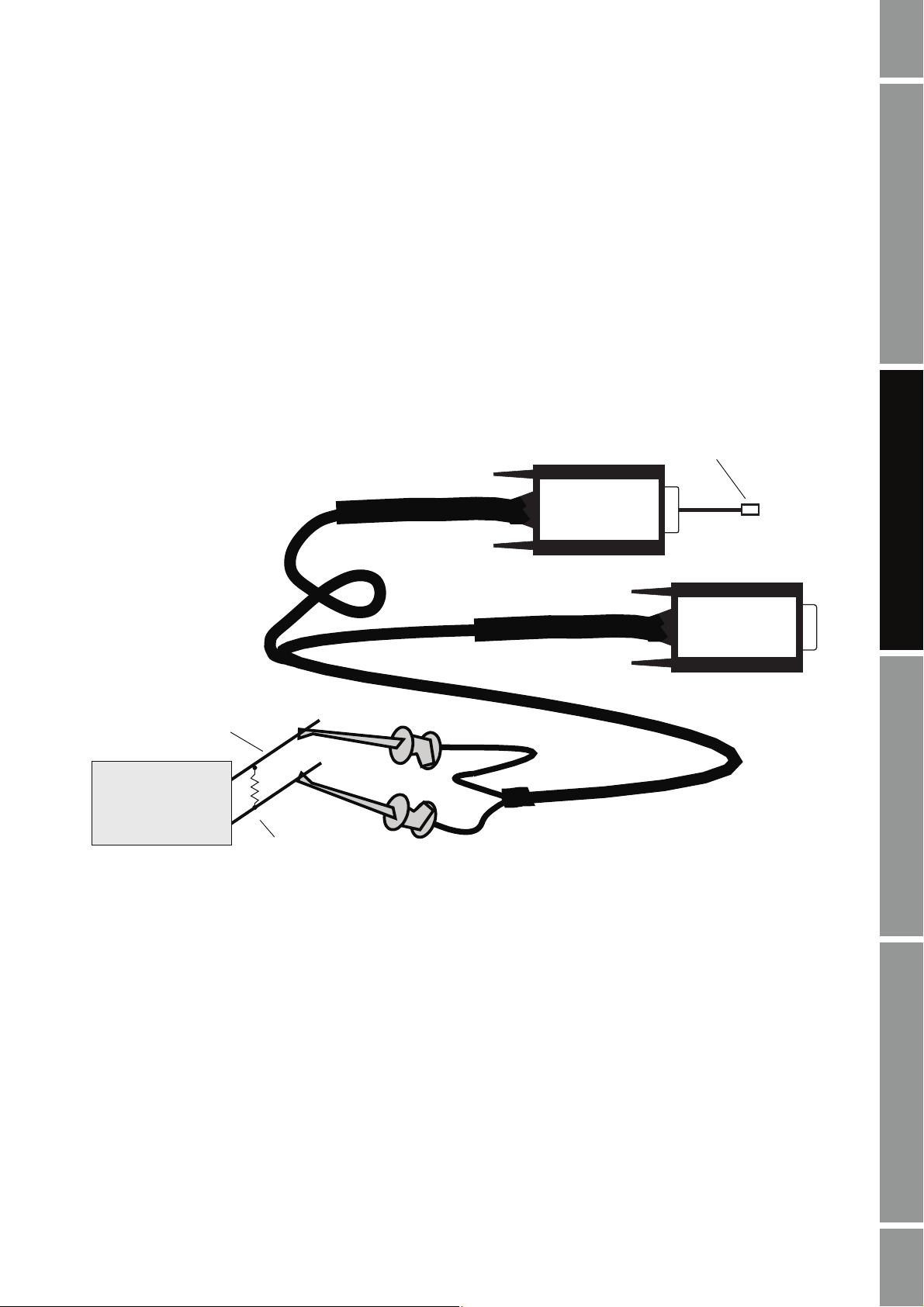
Method 2: HART/Bell 202 temporary connection to RFT9739 field-mount and RFT9712 transmitters
1. At the PC, connect the VIATOR HART Interface to the PC’s serial or USB port.
2. Open the transmitter’s wiring compartment.
3. Locate the Bell 202 hookups inside the wiring compartment and attach the VIATOR HART
Interface leads to the prongs (see Figure 2-2). The connection is polarity-insensitive; you can
attach either lead to either prong. For assistance in locating the Bell 202 hookups, see
Appendix A.
4. If necessary, add resistance in the loop by installing resistor R1 with a resistance of
250–1000 Ω
. Note that the hookups use the same circuit as the primary mA output, so the
required resistance may already be installed if the primary mA output loop is connected to a
remote device.
Figure 2-2 Attaching the VIATOR HART Interface to the prongs
Prongs
Transmitter
R1
or
VIATOR
USB plug
VIATOR
ProLink II Setup Transmitter StartupUsing ProLink IIBefore You Begin
Installation and Use Manual 15
Page 22
Installation and Setup
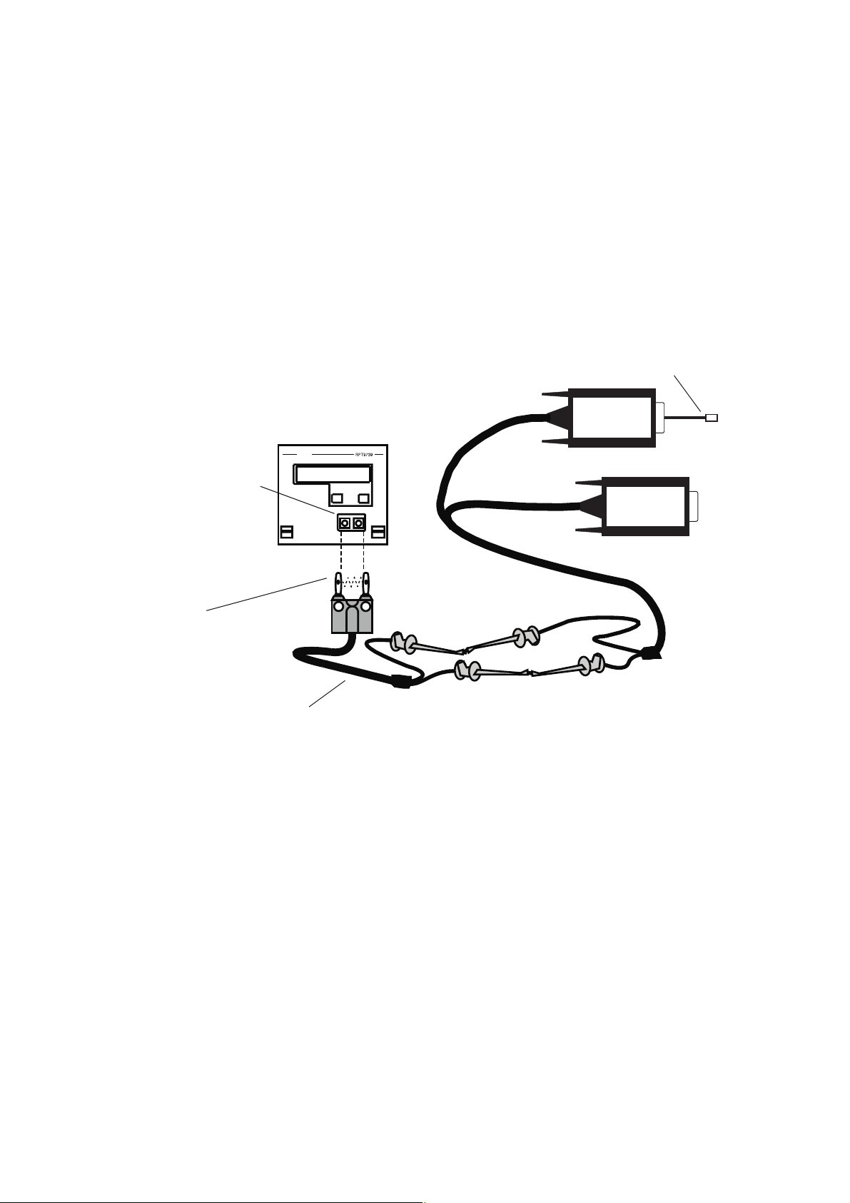
Method 3: HART/Bell 202 temporary connection to RFT9739 rack-mount transmitters
1. At the PC, connect the VIATOR HART Interface to the PC’s serial or USB port.
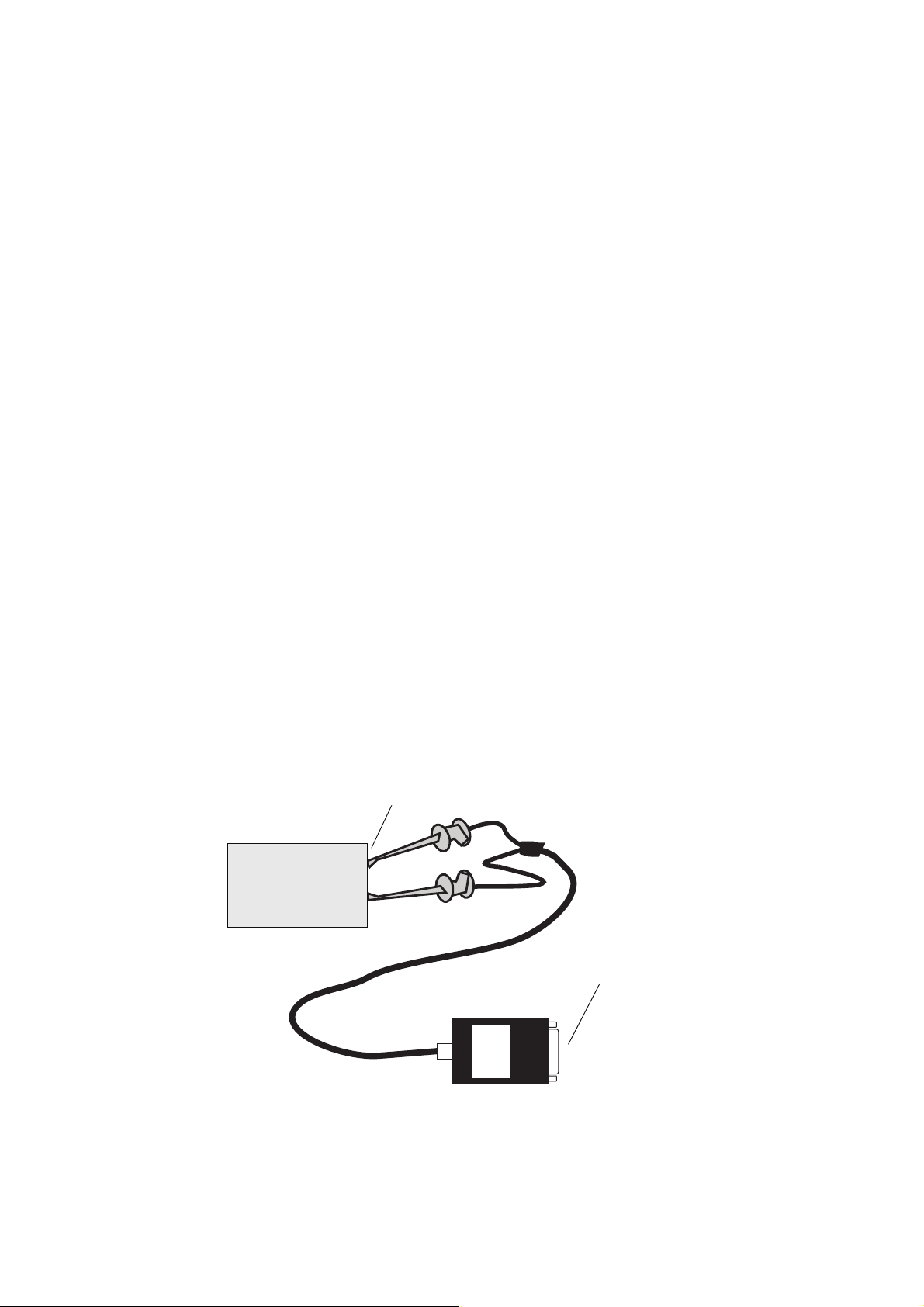
2. Attach the leads of a Bell 202 cable to the leads of the VIATOR HART Interface, and insert the
cable prongs into the HART jack on the transmitter’s faceplate (see Figure 2-3). The
connection is polarity-insensitive; you can insert the cable prongs in either direction.
3. If necessary, add resistance in the loop by installing resistor R1 with a resistance of
250–1000 Ω
. Note that the hookups use the same circuit as the primary mA output, so the
required resistance may already be installed if the primary mA output loop is connected to a
remote device or a HART network.
Figure 2-3 Using the HART jack
USB plug
VIA
TOR
HART jack
R1
Bell 202 cable (not included)
or
VIA
TOR
16 ProLink® II Software for Micro Motion® Transmitters
Page 23

Installation and Setup
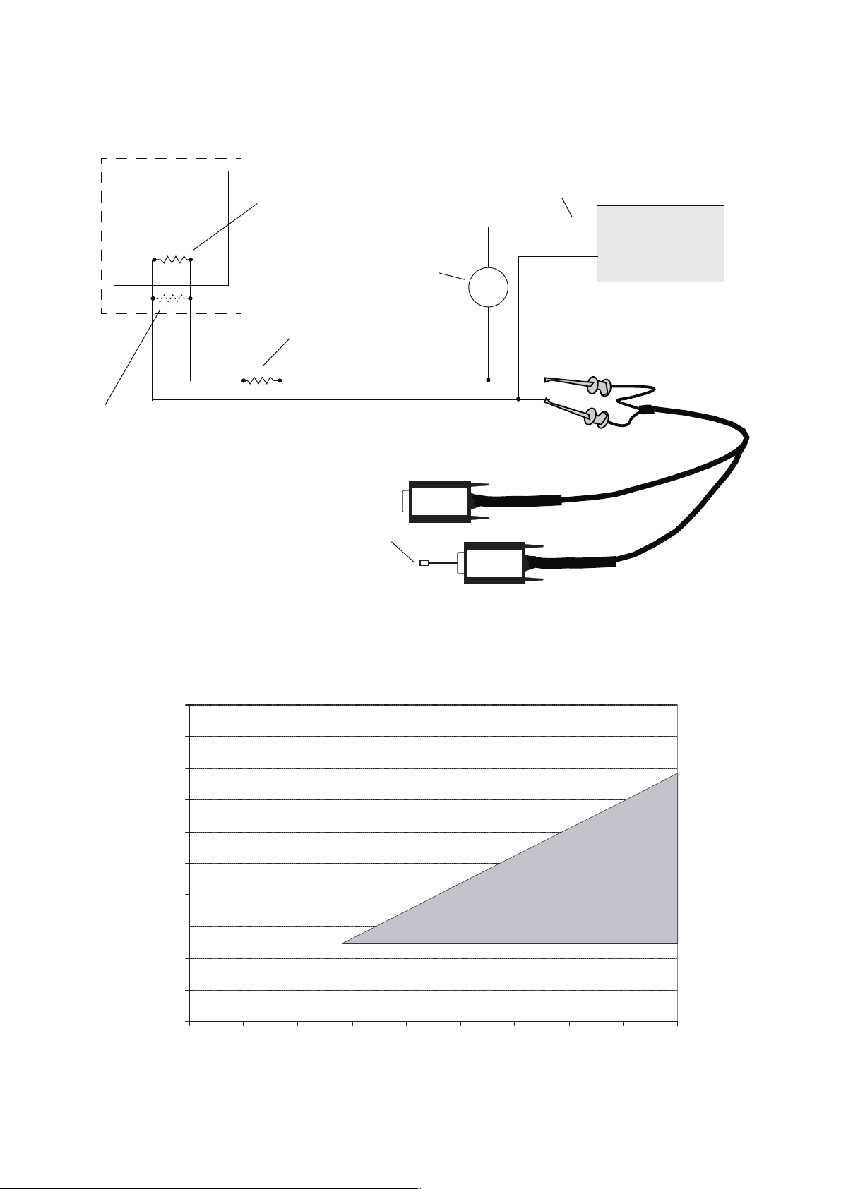
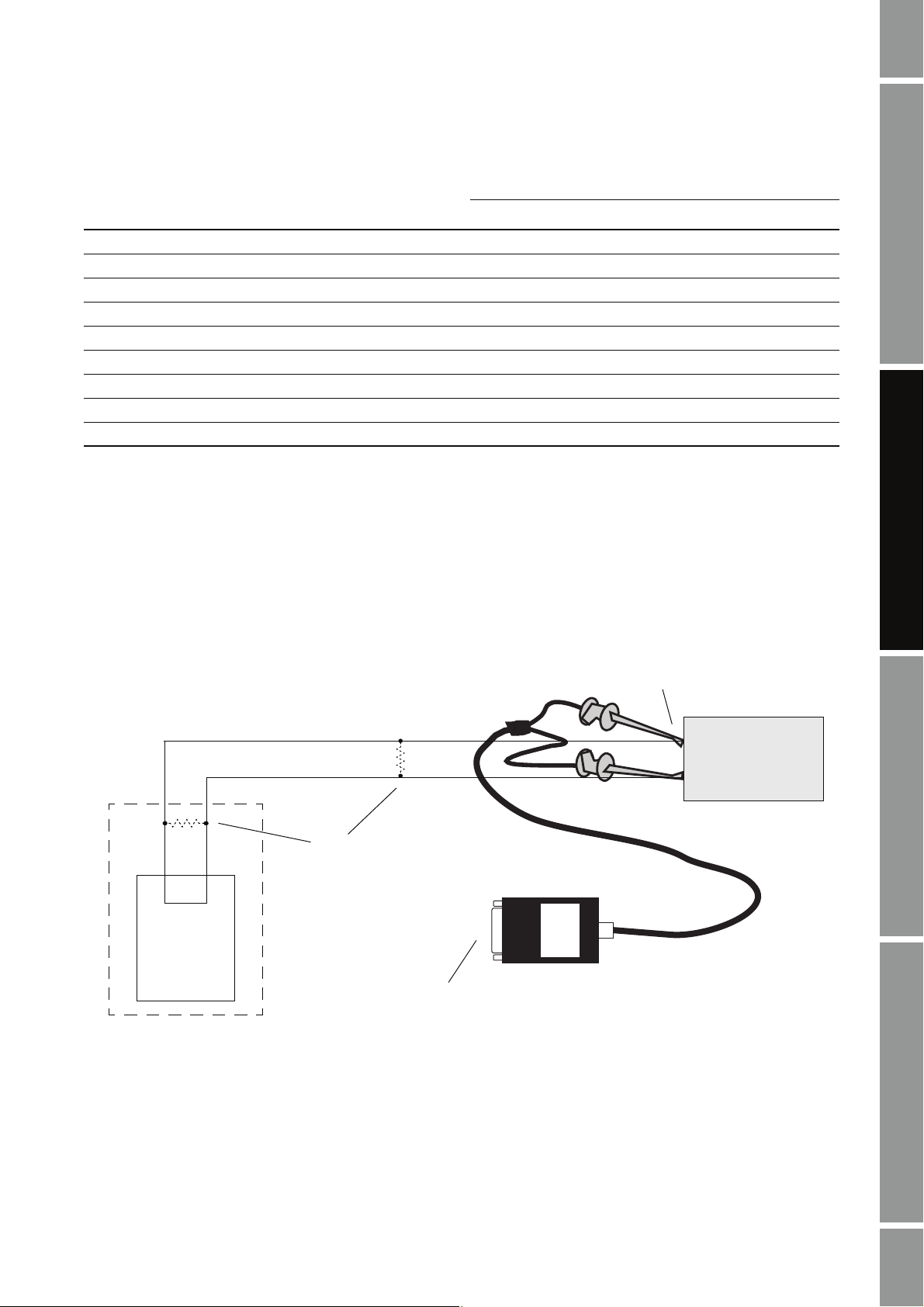
Method 4: HART/Bell 202 temporary or hard-wired connection to Model 1700/2700 IS transmitters
Using a VIATOR HART Interface, the PC can be connected directly to a transmitter’s primary mA
output terminals, to the output wires from these terminals, or to any point in a multidrop network that
is wired to these terminals. Figure 2-4 shows the wiring for this connection type.
1. At the PC, connect the VIATOR HART Interface to the PC’s serial or USB port.
2. Attach the VIATOR HART Interface leads:
• To any point on the network (hard-wired connection)
• Directly to the primary mA output terminals on your transmitter (temporary connection).
• To the output wires from the primary mA output terminals on your transmitter (hard-wired
The connection is polarity-insensitive; you can attach either lead to either terminal. For
assistance in identifying the primary mA output terminals, see Appendix A.
Tabl e 2-8 Primary mA output terminals – Method 4
See Table 2-8
connection). See Table 2-8
ProLink II Setup Transmitter StartupUsing ProLink IIBefore You Begin
Termi na ls
Transmitter
Model 1700/2700 IS 1 2
PV + PV –
3. Ensure that your wiring meets the following requirements:
• For basic analog output operation, the primary mA output requires an external power
supply with a minimum of 250 Ω and 17.5 volts. See Figure 2-5.
• For communication, the VIATOR HART Interface must be connected across a resistance
of 250–600 Ω. See Figure 2-4.
To meet the resistance requirements, you may use any combination of resistors R1, R2,
and R3:
- If no other device is connected to the primary mA output, add resistor R1 in series with the
primary mA output.
- If the primary mA output is connected to a remote device such as a DCS or a PLC with an
internal resistor (R2), ensure its value is between 250 and 600 Ω. If it is lower than 250 Ω,
add resistor R1 to the connection so that the overall resistance (R1 + R2) is between 250
and 600 Ω.
- If your DCS or PLC does not have an internal resistor, add resistor R3 and make sure its
value is between 250 and 600 Ω
.
Installation and Use Manual 17
Page 24
Installation and Setup
Figure 2-4 HART/Bell 202 connection to Model 1700/2700 IS transmitters
DCS or
PLC
R3
See Step 3
R2
See Step 3
External power supply
R1
See Step 3
See Step 3
+
–
Primary mA output terminals
See Step 2
+
Transmitter
–
VIATOR
or
USB plug
VIATOR
Figure 2-5 Model 1700/2700 IS transmitters: Resistance and voltage requirements for HART/Bell 202
connections
R
1000
900
800
700
600
500
400
= (V
A minimum of 250 ohms and 17.5 volts is required
max
– 12)/0.023
supply
Operating range
300
External resistance (Ohms)
200
100
0
12 3014 16 18 20 22 24 26 28
Supply voltage VDC (Volts)
18 ProLink® II Software for Micro Motion® Transmitters
Page 25

Installation and Setup
Method 5: HART/RS-485 temporary or hard-wired connection to transmitter or multidrop network
Note: This method is supported by RFT9739 and RFT9712 transmitters, by Model 1700/2700
transmitters with the analog outputs option board, and Series 3000 transmitters.
Using a Black Box signal converter, the PC can be connected directly to a transmitter’s RS-485
terminals, to the output wires from these terminals, or to any point on a multidrop network. Figure 2-6
shows the wiring for this connection type.
1. Ensure that your transmitter’s RS-485 terminals are configured for HART protocol. See the
transmitter manual for instructions.
2. If you are using an RFT9712 transmitter, you must set a jumper on the transmitter for RS-485
communications. See the transmitter manual for instructions.
3. At the PC, attach the Black Box signal converter to the PC’s serial or USB port, using a 25-pin
to 9-pin adapter if necessary. Ensure that the positive and negative wires are connected as
shown in Table 2-9 and Figure 2-6.
4. Attach the other end of the signal converter leads:
• To any point on the network (hard-wired connection)
• Directly to the RS-485 terminals on your transmitter (temporary connection). See
• To the output wires from the RS-485 terminals on your transmitter (hard-wired
For assistance in identifying the RS-485 terminals, see Appendix A.
5. For long-distance communication, or if noise from an external source interferes with the
signal, add two 120-Ω terminating resistors (R1) at each end of the RS-485 network.
ProLink II Setup Transmitter StartupUsing ProLink IIBefore You Begin
Tabl e 2 -9
connection). See Table 2-9
Tabl e 2-9 Lead-to-terminal assignments – Method 5
Termi na ls
Transmitter
Model 1700/2700 AN 5 6
Series 3000 panel-mount with screw-type connectors a32 c32
Series 3000 panel-mount with I/O cables 25 24
Series 3000 rack-mount a32 c32
Series 3000 field-mount 12 11
RFT9712 21 22
RFT9739 field-mount 27 26
RFT9739 rack-mount Z22 D22
RS-485/A RS-485/B
Installation and Use Manual 19
Page 26
Installation and Setup
Figure 2-6 HART/RS-485 connection to transmitter or multidrop network
R1
See Step 5
BLACK
BOX
RS-485 terminals
See Step 4
Transmitter
DCS or
PLC
25-pin to 9-pin serial port adapter
(if necessary) (not shown)
Method 6: Modbus/RS-485 temporary or hard-wired connection to RS-485 multidrop network
Note: This method is supported by RFT9739 transmitters, by Model 1500/2500 transmitters, by Model
1700/2700 transmitters with the analog outputs option board, and by Series 3000 transmitters.
Using a Black Box signal converter, the PC can be connected directly to a transmitter’s RS-485
terminals, to the output wires from these terminals, or to any point on an RS-485 network. Figure 2-7
shows the wiring for this connection type.
1. At the PC, attach the Black Box signal converter to the PC’s serial or USB port, using a 25-pin
to 9-pin adapter if necessary.
2. Attach the other end of the signal converter leads:
• To any point on the network (hard-wired connection). Ensure that the positive and negative
wires are connected as shown in Table 2-9.
• Directly to the RS-485 terminals on your transmitter (temporary connection). See
Table 2-10.
• To the output wires from the RS-485 terminals on your transmitter (hard-wired
connection). See Table 2-10.
For assistance in identifying the RS-485 terminals, see Appendix A.
20 ProLink® II Software for Micro Motion® Transmitters
Page 27
Installation and Setup
Tabl e 2-1 0 Lead-to-terminal assignments – Method 6
Termi na ls
Transmitter
Model 1500/2500 33 34
Model 1700/2700 AN 5 6
Series 3000 panel-mount with screw-type connectors a32 c32
Series 3000 panel-mount with I/O cables 25 24
Series 3000 rack-mount a32 c32
Series 3000 field-mount 12 11
RFT9712 21 22
RFT9739 field-mount 27 26
RFT9739 rack-mount Z22 D22
RS-485/A RS-485/B
3. For long-distance communication, or if noise from an external source interferes with the
signal, install 120-Ω, 1/2-watt resistors (R1) across terminals of both end devices.
Note: The Modbus protocol allows only one Modbus master to be active on the network at any given
time. If you are connecting through a network, ensure that no other Modbus master devices are
currently active.
Figure 2-7 Modbus/RS-485 connection to RS-485 multidrop network
RS-485 terminals
See Step 2
ProLink II Setup Transmitter StartupUsing ProLink IIBefore You Begin
DCS or
PLC
R1
See Step 3
BLACK
BOX
25-pin to 9-pin serial port adapter
(if necessary) (not shown)
Tr an s m it t er
Installation and Use Manual 21
Page 28
Installation and Setup
Method 7: Modbus/RS-485 temporary connection to service port
Note: This method is supported by all Series 1000, Series 2000 and Series 3000 transmitters.
Using a Black Box signal converter, the PC can be connected directly to a transmitter’s service port.
Figure 2-8 shows the wiring for this connection type.
1. At the PC, attach the Black Box signal converter to the PC’s serial or USB port, using a 25-pin
to 9-pin adapter if necessary.
2. At the transmitter, connect the signal converter leads to the service port terminals. See
Table 2-11. For assistance in identifying the terminals, see Appendix A.
• If you are connecting to a Model 1700/2700 or to a Model 2400S transmitter, the service
• If you are connecting to a Model 1500/2500 transmitter or a Series 3000 transmitter, the
port terminals are available at any time.
RS-485 terminals on these transmitters are accessible as a service port for a 10-second
interval after power-up:
- If a service port connection is made during this interval, the port will remain in service
port mode indefinitely until power is cycled.
- If no service port connection is made during this interval, the terminals switch to
Modbus/RS-485 mode, and must be accessed using the RS-485 communication
settings configured in the transmitter (see Method 6).
Service port connections to these transmitters are discussed in detail in Section 2.2.6.
Note: The Modbus protocol allows only one Modbus master to be active on the network at any given
time. If you are connecting through a network, ensure that no other Modbus master devices are
currently active.
Note: All service ports are accessed using the default address of 111. If you are connecting over a
multidrop network with multiple service ports, it is not possible to specify which device to connect to.
Figure 2-8 Modbus/RS-485 connection to the service port
Service port terminals
See Step 2
Transmitter
25-pin to 9-pin serial port adapter
(if necessary) (not shown)
BLACK
BOX
22 ProLink® II Software for Micro Motion® Transmitters
Page 29
Installation and Setup
Tabl e 2-1 1 Lead-to-terminal assignments – Method 7
Terminals
Transmitter
Model 1500/2500 transmitters 33 34
All Model 1700/2700 transmitters 8 7
All Model 2400S transmitters
Series 3000 panel-mount with screw-type connectors a32 c32
Series 3000 panel-mount with I/O cables 25 24
Series 3000 rack-mount a32 c32
Series 3000 field-mount 12 11
(1) On Model 2400S transmitters, service port connections are made via the service port clips which are located on the user interface.
Alternatively, service port connections are possible via the transmitter infrared port. For more information on using the infrared port,
refer to the transmitter configuration and use manual.
(1)
RS-485/A RS-485/B
AB
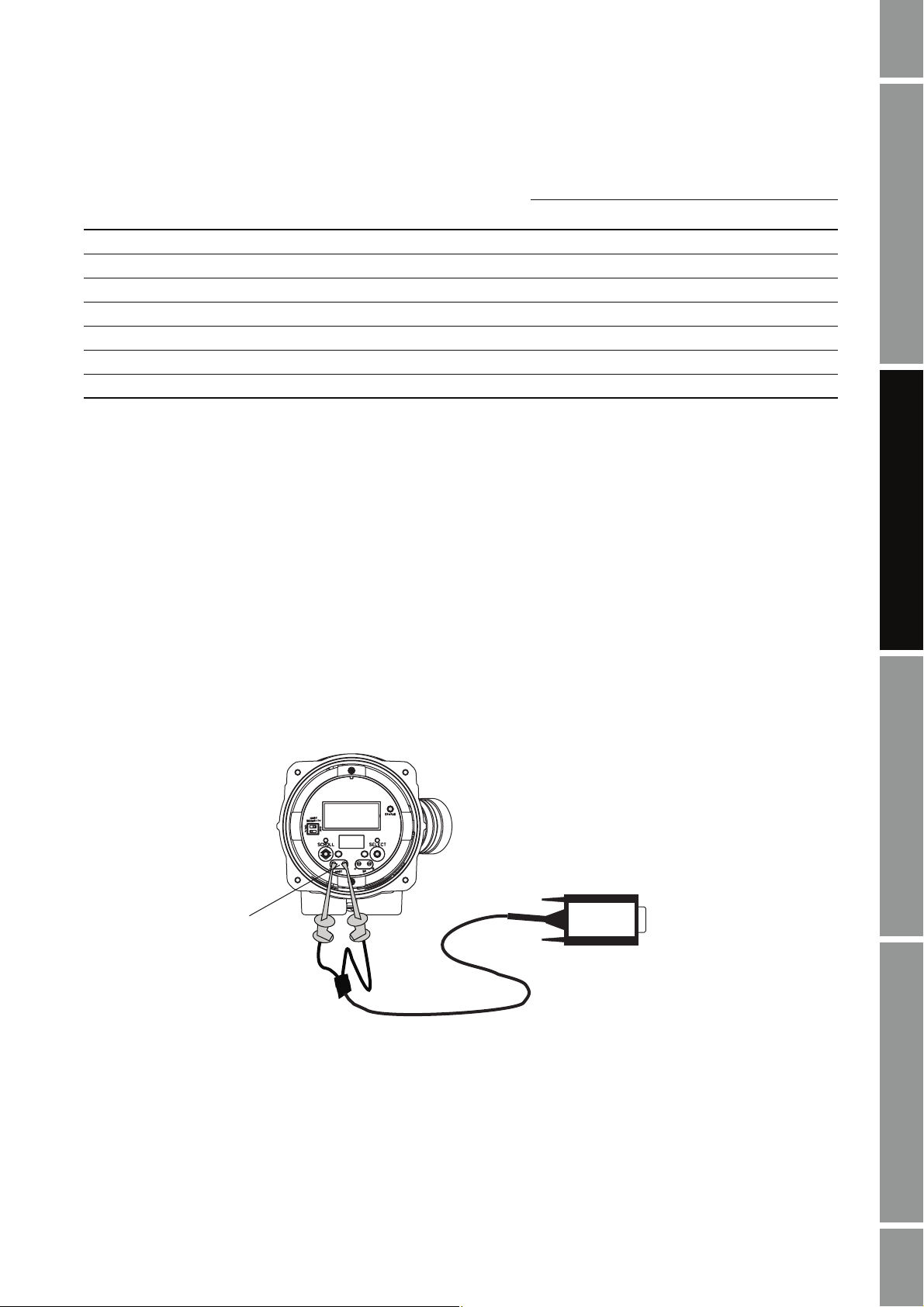
Method 8: HART/Bell 202 temporary connection to HART clips
Note: This method is supported by Model 2400S transmitters that support HART communication.
Using a VIATOR HART Interface, the PC can be connected directly to the HART clips on the face of
the transmitter. Figure 2-9 shows the wiring for connection to the HART clips.
1. At the PC, attach the VIATOR HART Interface to the PC’s serial or USB port, using a 25-pin
to 9-pin adapter if necessary.
2. At the transmitter, remove the housing cover.
3. Connect the HART interface leads to the HART clips.
ProLink II Setup Transmitter StartupUsing ProLink IIBefore You Begin
Figure 2-9 HART/Bell 202 connection to HART clips
HART clips
4. If necessary, add a resistance across the HART clips. The VIATOR HART interface must be
connected across a resistance of 250–600 Ω. Note that the HART clips use the same circuit as
the mA output, so the required resistance may already be installed if the mA output loop is
connected to a remote device or a HART network (see Figure 2-1).
VIATOR
Installation and Use Manual 23
Page 30

Installation and Setup
Method 9: Modbus/RS-485 temporary connection to MVD Direct Connect
Using a Black Box signal converter, the PC can be connected directly to the RS-485 terminals on the
core processor or the MVD Direct Connect I.S. barrier.
1. At the PC, attach the Black Box signal converter to the PC’s serial or USB port, using a 25-pin
to 9-pin adapter if necessary.
2. If connecting to the core processor, remove the lid.
3. Connect the signal converter leads to the RS-485 terminals. See Table 2-12, and:
• For connecting to the standard core processor, see Figure 2-10.
• For connecting to the enhanced core processor, see Figure 2-11.
• For connecting to the I.S. barrier, see Figure 2-12.
Note: The Modbus protocol allows only one Modbus master to be active on the network at any given
time. If you are connecting through a network, ensure that no other Modbus master devices are
currently active.
Note: Before using ProLink II to communicate with the core processor, disconnect any wiring to a
remote PLC. Be careful not to disconnect the power supply wiring. After using ProLink II to
communicate with the core processor, reconnect the wiring to the remote PLC.
Tabl e 2-1 2 Lead-to-terminal assignments – Method 9
Terminals
Device
I.S. barrier
Core processor
(1) Connection is intrinsically safe.
(2) Connection is not intrinsically safe.
(1)
(2)
RS-485/A RS-485/B
13 14
34
Figure 2-10 Modbus/RS-485 connection to RS-485 terminals on standard core processor
RS-485/B
Core processor
25 to 9 pin serial port
adapter (if necessary)
RS-485/A
24 ProLink® II Software for Micro Motion® Transmitters
RS-485 to RS-232
signal converter
Page 31

Installation and Setup
Figure 2-11 Modbus/RS-485 connection to RS-485 terminals on enhanced core processor
RS-485/A
Core processor
RS-485/B
25 to 9 pin serial port
adapter (if necessary)
RS-485 to RS-232
signal converter
Figure 2-12 Modbus/RS-485 connection to RS-485 terminals on I.S. barrier
RS-485/B
RS-485/A
ProLink II Setup Transmitter StartupUsing ProLink IIBefore You Begin
I.S. barrier
Non-I.S. terminals
Installation and Use Manual 25
25 to 9 pin serial port
adapter (if necessary)
RS-485 to RS-232
signal converter
Page 32

Installation and Setup
2.2.6 Configure ProLink II connection parameters and connect to the transmitter
To connect to the transmitter, ProLink II must use connection parameters appropriate to the
transmitter.
• If you are connecting to an MVD Direct Connect system, ProLink II can use any of the
supported communication settings listed in Table 2-13. The core processor auto-detects
incoming communications parameters and switches to match.
• If you are connecting to a Model 2400S transmitter using the service port:
- For point-to-point connections, you can use a service port connection type.
- For multidrop network connections, you can use any Modbus/RS-485 connection type and
• If you use a service port or HART/Bell 202 connection type, the connection parameters are
standard: when one of these connection types is specified, ProLink II automatically uses the
appropriate parameters.
- HART/Bell 202 connections are always available on all transmitters.
- Service port connections are always available for all Model 1700/2700 transmitters and for
- For Model 1500/2500 transmitters and Series 3000 transmitters, the RS-485 terminals are
specify the transmitter’s Modbus address. The transmitter auto-detects incoming
communications parameters and switches to match. The service port auto-detection limits
are described in Table 2-14.
all Model 2400S transmitters.
accessible as a service port for a 10-second interval after power-up:
- If a service port connection is made during this interval, the port will remain in service
port mode indefinitely until power is cycled.
- If no service port connection is made during this interval, the terminals switch to
Modbus/RS-485 mode, and must be accessed using the RS-485 communication
settings configured in the transmitter.
• If you use any other connection type, you must configure ProLink II connection parameters to
match the transmitter’s configuration. If you do not know the transmitter’s configuration, you
can use a Communicator or the transmitter’s display to view or change its configuration.
- For all transmitters, if you are using HART protocol, you can specify the transmitter’s
HART tag (software tag) instead of the HART address, if a HART tag has been configured
in the transmitter.
- For all Series 1000/2000/3000 transmitters, see Table 2-15 for default values for each
connection type.
- For IFT97xx transmitters, communication parameters are not configurable. Settings are
listed in Table 2-16. Configure ProLink II connection parameters to match these settings.
- For RFT97xx transmitters, communication is configured using switches and jumpers on
the transmitter. Check your transmitter and refer to the transmitter manual to determine
your transmitter’s configuration, then configure ProLink II connection parameters to
match these settings. Factory default settings for these transmitters are listed in Table 2-16.
For a discussion of the advantages of each connection type, see Section 3.3.1.
26 ProLink® II Software for Micro Motion® Transmitters
Page 33

Installation and Setup
Tabl e 2-1 3 MVD Direct Connect auto-detection limits
Parameter Option
Protocol Modbus RTU (8-bit)
Modbus ASCII (7-bit)
Baud rate Standard rates between 1200 and 38,400
Parity Even, odd, none
Stop bits 1, 2
Tabl e 2-1 4 Model 2400S service port auto-detection limits
Parameter Option
Protocol Modbus RTU (8-bit)
Modbus ASCII (7-bit)
Address Responds to both:
• Service port address (111)
• Configured Modbus address (default=1)
Baud rate Standard rates from 1200 to 38,400
Stop bits 1, 2
Parity Even, odd, none
ProLink II Setup Transmitter StartupUsing ProLink IIBefore You Begin
Tabl e 2-1 5 Default communication parameters for Series 1000/2000/3000 transmitters
Default values
Data
Transmitter Physical layer Protocol Baud
Model 1500/2500 Bell 202
RS-485
Model 1700/2700 AN Bell 202
RS-485
Model 1700/2700 IS
Bell 202
(2)(3)
(5)
(2)
(5)(6)
(2)
Model 2700 CIO
Model 2400S AN Bell 202
(2)
RS-485 Modbus
Series 3000 Bell 202
RS-485
(2)
(5)
(1) ProLink II automatically sets data bits appropriately for the configured protocol. Even though a data bits parameter may be
configured in the transmitter, you do not need to configure it in ProLink II. HART protocol is always 8 data bits. If your transmitter
is configured for Modbus with 7 data bits, specify Modbus ASCII; if your transmitter is configured for Modbus with 8 data bits,
specify Modbus RTU.
(2) Connection to primary mA output, or to HART clips (Model 2400S transmitters only).
(3) Except Model 1500 transmitter with the Filling and Dosing application. The Model 1500 transmitter with the Filling and Dosing
application does not support Bell 202 / HART communication.
(4) HART/Bell 202 parameters are not configurable. The settings shown here are always in effect.
(5) Connection to RS-485 terminals.
(6) Available only on Model 1700/2700 transmitters with analog outputs.
(4)
HART
1200 8 1 odd 0
Modbus RTU 9600 8 1 odd 1
(4)
HART
1200 8 1 odd 0
HART 1200 8 1 odd 0
(4)
HART
HART
(4)
1200 8 1 odd 0
1200 8 1 odd 0
Auto-
(RTU or ASCII)
(4)
HART
detect
1200 8 1 odd 0
Modbus RTU 9600 8 1 odd 1
bits
Autodetect
Stop
(1)
bits Parity Address
Autodetect
Autodetect
1
Installation and Use Manual 27
Page 34

Installation and Setup
Tabl e 2-1 6 Default communication parameters for RFT97xx and IFT97xx transmitters
Default values
Transmitter Physical layer Protocol Baud Data bits
IFT9701/9703
RFT9712 Bell 202
RFT9739 v2 Bell 202
RFT9739 v3 Bell 202
(1) ProLink II automatically sets data bits appropriately for the configured protocol. Even though a data bits parameter may be
configured in the transmitter, you do not need to configure it in ProLink II.
(2) IFT9701/9703 communication parameters are not configurable. The settings shown here are always in effect.
(3) Connection to primary mA output.
(4) Connection to RS-485 terminals.
(5) Dip switch settings on the transmitter are used to select either Std. comm or User defined.
(2)
Bell 202
RS-485
RS-485
RS-485
• Std. comm Modbus RTU 9600 8 1 odd 1
• User defined HART 1200 8 1 odd 0
(3)
(3)
(4)
(3)
(4)
(3)
(4)(5)
HART 1200 8 1 odd 0
HART 1200 8 1 odd 0
HART 1200 8 1 odd 0
HART 1200 8 1 odd 0
HART 1200 8 1 odd 0
HART 1200 8 1 odd 0
(1)
Stop bits Parity Address
To make the software connection from ProLink II to your transmitter.
1. Ensure that your PC is connected to the transmitter, according to one of the methods described
in Section 2.2.5.
2. Start ProLink II software.
3. From the
Connection menu, click on Connect to Device.
4. Specify connection parameters:
•Use the
connections using the VIATOR USB HART Interface, enable
•Set
Protocol parameter to specify your connection type. For HART/Bell 202
Converter Toggles RTS.
Serial Port to the PC COM port you are using to connect to the transmitter.
• If you are making a service port or HART/Bell 202 connection, default values are used for
all remaining connection parameters.
• If you are connecting to MVD Direct Connect, set the remaining connection parameters to
any of the supported settings listed in Table 2-13.
• For all other connection types:
- For Model 2400S transmitters, set the address to the Modbus address configured for
your transmitter.
Note: Due to the transmitter’s auto-detection feature, other connection parameters are not required.
- For all other transmitters, set the remaining connection parameters to the values
configured in your transmitter.
28 ProLink® II Software for Micro Motion® Transmitters
Page 35

Installation and Setup
5. If you are making a service port connection to a Model 1500/2500 transmitter or a Series 3000
transmitter:
a. Power down the transmitter.
b. Restore power to the transmitter.
c. Wait 1–5 seconds. On the Series 3000, wait until the display begins to flash.
6. Click the
Connect button. ProLink II will attempt to make the connection.
7. If an error message appears, see Section 2.4.
2.2.7 Obtain and configure a site key
To obtain and configure a site key:
1. Open the License Request file as follows:
Start > Programs > MMI > ProLink II v2.5 > ProLink II License Request Form
2. Edit the file, supplying all requested information including the site code.
The site code is provided in the
be opened from the ProLink II
License window (see Figure 2-13). The License window can
File menu.
Note: To minimize the possibility of error, Micro Motion recommends copying and pasting the site
code, rather than typing the value.
3. Save the edited file.
4. Contact Micro Motion in one of the following ways:
• Send an email to:
ProLink.Support@EmersonProcess.com
and attach the edited file to the email. The file is named LicenseRequest.txt, and in
typical installations is located in
Program Files > MMI > ProLink II v2.5.
ProLink II Setup Transmitter StartupUsing ProLink IIBefore You Begin
Note: This is the default location. If the ProLink II installation program found an existing license file,
the program and License Request file were installed in the location of the license file.
• Telephone 800-522-6277 (toll-free in the U.S.), or 303-530-8350 (worldwide), and request
a site key. Have the edited registration text file available for reference.
Note: To minimize the possibility of error, Micro Motion recommends using the email method.
5. When the site key is provided:
a. Start ProLink II.
b. From the
File menu, click License. The window shown in Figure 2-13 is displayed.
Installation and Use Manual 29
Page 36

Installation and Setup
Figure 2-13 License window
c. Enter the site key into the
Site Key textbox, then click the Validate button.
Note: To minimize the possibility of error, Micro Motion recommends copying and pasting the site key,
rather than typing the value.
2.3 Troubleshooting the ProLink II installation
If you have problems with the ProLink II installation, review the information in this section and
follow the suggestions. If you cannot resolve the problem, contact Micro Motion customer support.
2.3.1 Insufficient privileges
If you are unable to install ProLink II on a Windows NT, Windows 2000, or Windows XP system,
verify that you have the required privileges (see Section 2.2.1). On Windows NT, you must be logged
on as Administrator to perform the ProLink II installation.
2.3.2 Missing or corrupt registry entries
During a successful ProLink II installation, information is written to the Windows registry. If, for any
reason, ProLink II information in the registry is corrupted or missing, you can replace or update the
required information as follows:
1. Click
Start > Programs > MMI > ProLink II v2.5 > ProLink II Registrar.
2. A batch file that updates the Windows registry will be executed. Click
pop-up messages.
3. Close the command window.
OK as required by the
Note: To run the batch file on Windows NT, Windows 2000, or Windows XP systems, you must be
authorized to write to the registry.
30 ProLink® II Software for Micro Motion® Transmitters
Page 37

Installation and Setup
2.4 Troubleshooting the ProLink II connection
If you cannot connect to the transmitter, review the information in this section and follow the
suggestions. If you cannot resolve the problem, contact Micro Motion customer support.
2.4.1 OPC server or OPC client issues
If the Context message displays either of the following:
The OPC server could not be started.
The OPC client database could not be opened.
reinstall ProLink II, ensuring that you have the required privileges (see Section 2.2.1). On
Windows NT, you must be logged on as Administrator to perform the ProLink II installation.
2.4.2 Other issues
If the Context message displays either of the following:
The serial port could not be opened, or the device did not respond. Port availability and
connection wiring should be checked.
An unexpected error code was returned.
try the following:
ProLink II Setup Transmitter StartupUsing ProLink IIBefore You Begin
1. Check all the wiring between the PC and the transmitter, and ensure that all components are
powered up. See the setup information for your connection type in Section 2.2.5, or refer to the
transmitter manual.
2. Check all the connection parameters – baud rate, parity, stop bits, protocol, address, and COM
port – and ensure they are correct for both ProLink II and the transmitter.
3. Click
Start > Programs > MMI > ProLink II v2.5 > ProLink II Registrar. This program
updates registry entries.
4. Ensure that ProLink II is configured for the correct COM port. To do this, install the LED
indicator/tester. (If you purchased the ProLink II installation kit from Micro Motion, this
device was included.) Attempt a connection.
• The indicators for the TD, RD, DTR, and RTS lines should be ON. Usually they are red,
but if another program has used the COM port the RTS indicator may be green. If no
indicators are ON, you are not connected to the COM port, ProLink II is configured for the
wrong COM port, or there is a wiring problem.
• When you try to connect, verify that the RTS LED changes color or flashes. If no LED
change is detected, you are connected to the wrong COM port or the COM port isn’t
assigned correctly. Check the device manager on your PC for the proper COM port
configuration.
5. Make sure that you don’t have interference over the COM port. Other programs or devices
may be trying to use the COM port. If the TD light is flashing while you are not using
ProLink II, the COM port is in use by another program. Terminate the other program and try
again.
6. If you use the configured COM port for any other program, verify that the other program is not
currently running. Personal digital assistants (PDAs) often have automatic update programs
that use the COM ports continually.
7. For HART connections to Model 1700/2700 transmitters with the intrinsically safe outputs
option board, ensure that the terminals are externally powered.
Installation and Use Manual 31
Page 38

Installation and Setup
8. Try adding resistance to the connection.
• For HART connections, refer to the installation instructions earlier in this chapter. Verify
• For HART connections to Model 1700/2700 transmitters with the intrinsically safe outputs
• RS-485 connections may require added resistance if the connection is long-distance or if
9. For RS-485 connections, swap the leads between the two terminals and try again.
10. For Modbus network connections, ensure that ProLink II is the only Modbus master active on
the network.
11. For RS-485 connections, try connecting through the service port, if available on your
transmitter.
12. For HART/Bell 202 connections:
a. If burst mode in enabled, try disabling it.
b. Ensure that polling for external pressure/temperature is disabled.
c. Ensure that ProLink II is the only master on the network.
that there is a 250–600 Ω resistor in parallel in the communications circuit.
option board, ensure that the resistor is in series. Attach the modem across the resistor.
there is external noise that interferes with the signal. Add two 120-Ω resistors in parallel
with the output, one at each end of the communication segment.
13. For HART connections using the VIATOR USB HART Interface:
a. Ensure that you have checked the box labeled
Connect window.
Converter Toggles RTS in the ProLink II
b. Ensure that the required Windows driver is installed on your PC. If this driver is not
installed, Windows will not recognize the USB converter when it is plugged into the USB
port.
14. For connections to the Model 2400S transmitter, if you are using Modbus ASCII protocol with
an RS-485 connection rather than a service port connection, ensure that Modbus ASCII
support is enabled on your transmitter.
32 ProLink® II Software for Micro Motion® Transmitters
Page 39

Chapter 3
Using ProLink II Software
3.1 Overview
This chapter provides information on the ProLink II user interface, including:
• Starting ProLink II and connecting to a transmitter (see Section 3.3)
• The ProLink II help system (see Section 3.4)
• Viewing installed options (see Section 3.5)
• Viewing process data (see Section 3.6)
• Viewing and resetting totalizers and inventories (see Section 3.7)
• Viewing status and alarms (see Section 3.8)
• Managing the ProLink II license (see Section 3.10)
ProLink II Setup Transmitter StartupUsing ProLink IIBefore You Begin
3.2 ProLink II user interface
ProLink II software is designed to be easy to use in a Windows environment. ProLink II uses standard
Windows methods for viewing and selecting options.
3.3 Startup
ProLink II can be started from the Windows Start menu, where it is usually found in the MMI
program group. You can also define a desktop shortcut for running ProLink II.
When ProLink II first starts up, the ProLink II main screen and
(see Figure 3-1). Until you connect to a transmitter, most of the menu options are disabled.
Connect dialog box are displayed
Installation and Use Manual 33
Page 40

Using ProLink II Software
Figure 3-1 ProLink II main window and Connect dialog box
3.3.1 Connecting to a transmitter
Depending on your transmitter, you may have several different options for making the connection
from ProLink II to the transmitter. Review the following connection guidelines when selecting your
connection method. Instructions for making the connection are provided following the guidelines.
Connection guidelines
• You must have the appropriate signal converter for the connection type you choose. See
Section 2.2.5.
• Modbus connections are faster than HART connections.
• Using a HART connection from ProLink II, you cannot have more than one client window
open at a time.
• Service port connections
- Service port connections are available on all MVD transmitters.
- Service ports use standard connection parameters, so you do not have to know the
transmitter’s configuration.
- ProLink II uses Modbus protocol for service port connections, which is the fastest protocol
available.
- On Model 1700/2700 transmitters and Model 2400S transmitters, the service port is
always available.
- On Model 1500/2500 transmitters and Series 3000 transmitters, the service port is
available only for ten seconds after power-up. For service port access, you will have to
power down the transmitter, which may not be acceptable in your installation.
- On Series 1700/2700 transmitters, you must open the wiring compartment to access the
service port. On Model 2400S transmitters, you must remove the housing cover.
Therefore, on these transmitters the service port is appropriate only for temporary
connections.
34 ProLink® II Software for Micro Motion® Transmitters
Page 41

Using ProLink II Software
• HART/Bell 202 connections
- HART/Bell 202 connections are available on all transmitters that have an mA output,
except the Model 1500 with the Filling and Dosing application. The transmitter
Model 1500 with the Filling and Dosing application does not support HART
communication.
- HART/Bell 202 connections use standard connection parameters, so you don’t have to
know the transmitter’s configuration.
- Because the HART/Bell 202 connection is made over the primary mA output terminals,
the communication signal can interfere with certain procedures such as loop testing, and
may cause the output to change. Depending on how the primary mA output is being used,
this may have significant consequences for process control.
- Depending on the transmitter and wiring method, HART/Bell 202 connections may be
appropriate for both temporary and permanent connections.
• RS-485 connections
- RS-485 connections are not available on all transmitters.
- To use an RS-485 connection, you must know the transmitter’s configuration.
- RS-485 connections are appropriate for both temporary and permanent connections.
ProLink II Setup Transmitter StartupUsing ProLink IIBefore You Begin
Making the connection
1. Ensure that your PC is connected to a transmitter, using one of the methods described in
Chapter 2.
2. If the
3. Select the protocol to use. Depending on the
Connect dialog box is not displayed:
a. Open the
b. Click on the
Connection menu.
Connect option.
Protocol option that you choose, different
communications options will be available for configuration.
Note: Due to the design of HART protocol, connections made using HART protocol are slower than
connections that use Modbus protocol. If you use HART protocol, you cannot open more than one
ProLink II window at a time.
Note: Windows NT does not support USB connections.
Note: If you are using a service port connection to a Model 1500/2500 transmitter or a Series 3000
transmitter, see Section 2.2.6 for instructions on making this connection.
4. Specify
Baud Rate, Parity, Stop Bits, COM Port, and Address/Tag as appropriate for your
connection and transmitter. See Section 2.2.6 for more information on these parameters.
Note: If you are using HART protocol and a HART tag (software tag) has been configured for your
transmitter, you can specify the HART tag instead of the HART address.
5. If you are using the Viator USB HART Interface, enable
6. Click the
Connect button.
Converter Toggles RTS.
Note: ProLink II can connect to only one transmitter at a time. To connect to another transmitter, you
must first disconnect from the current connection.
Installation and Use Manual 35
Page 42

Using ProLink II Software
Polling for devices
If you do not know the address of your transmitter:
1. Click the
display a list of all transmitters found.
2. Select the transmitter to connect to, and click
3.3.2 Disconnecting
To disconnect from the currently connected transmitter:
Poll button. ProLink II will poll the network for all Micro Motion transmitters, and
OK.
1. Open the
2. Click on the
Connection menu.
Disconnect option.
3.4 ProLink II help system
ProLink II provides context-sensitive help for most windows and dialog boxes.
• To access the complete help system, click on
• To access help for a specific window or dialog box, make the object active, then press F1.
3.5 Viewing installed options
A Series 1000/2000/3000 transmitter can be purchased with several application options. To view the
list of installed options:
1. Open the
2. Click on
View menu.
Installed Options. A window similar to Figure 3-2 is displayed. In this window, the
installed options are indicated with a checkmark.
Figure 3-2 Installed Options window
Help.
36 ProLink® II Software for Micro Motion® Transmitters
Page 43

Using ProLink II Software
3.6 Viewing process data
ProLink II provides the following windows for viewing process data and related information:
•
Process Variables window
•
Output Levels window
•
Tota lize r Control window
The following windows are available if the associated option has been installed on the transmitter:
•
API Process Variables window
•
ED (Enhanced Density) Process Variables window
All of these windows are opened from the
ProLink menu. For information on the data displayed in
these windows, see the transmitter manual, the application manual, or the ProLink II help system (see
Section 3.4).
3.7 Viewing and resetting totalizers and inventories
Totalizer Control window is used to:
The
• View current values of the totalizers and inventories
• Start, stop, and reset totalizers
• Reset inventories
• Reset frequency input total (Series 3000 transmitters only)
If the enhanced density application is available and enabled in the transmitter, the
Control
window is used to view and control totalizers and inventories related to the enhanced density
application.
Inventories can be reset only if this function is enabled in the
To enable inventory reset:
1. Open the
2. Click on
3. Ensure that
4. Click the
View menu.
Preferences.
Enable Inventory Totals Reset is checked.
Apply button if necessary.
To manage totalizers and inventories:
ProLink II Setup Transmitter StartupUsing ProLink IIBefore You Begin
ED Totalizer
Preferences menu.
1. Open the
2. Click on
ProLink menu.
Totalizer Control or ED Totalizer Control (if the enhanced density application is
enabled in the transmitter). A window similar to Figure 3-3 is displayed.
3. Use the buttons in this window to start, stop, or reset the totalizers and/or inventories.
Note: The
Start, Stop, and Reset buttons displayed under All Totals affect the mass totalizer, the
volume totalizer, and all API-related totalizers.
4. The
Reset Inventories button under All Totals is displayed only if this function is enabled
(see above). Use this button to reset all inventories, including API-related inventories.
Note: ProLink II does not support separate resetting of the API volume totalizer and API volume
inventory. To reset these, you must reset all totalizers or all inventories.
Installation and Use Manual 37
Page 44

Using ProLink II Software
Figure 3-3 Totalizer Control window
3.8 Viewing meter status
ProLink II allows you to view a variety of status information:
•
Connection LED – located in the lower right corner of the main window (see Figure 3-1).
This LED indicates the status of the connection between ProLink II and the transmitter:
- Green – Good connection
- Red – Connection fault
- Gray – No connection
•
Device Fault Status LED – located in the lower right corner of the main window (see
Figure 3-1). This LED indicates whether or not alarms are active:
- Green – No active alarms
- Red – One or more active alarms
- Gray – Unknown
See Section 3.9 for more information about alarms.
•
Diagnostic Information window – displays sensor diagnostic data
•
Output Levels window – displays current data for the transmitter’s mA, frequency, and
discrete outputs, and also displays discrete event status
•
Status window – displays alarm status. See Section 3.9 for more information about alarms.
•
Alarm Log window – displays alarm status and alarm acknowledgment status. See Section 3.9
for more information about alarms.
38 ProLink® II Software for Micro Motion® Transmitters
Page 45

Using ProLink II Software
• Core Processor Diagnostics window – displays detailed diagnostic data for the core
processor component
Note: The Core Processor Diagnostics window is always available for viewing. However, the Secure
option is required on the ProLink II license in order to make changes and update the device from this
window.
•
FingerPrint window – displays detailed information for both process variable data and sensor
diagnostic data
3.9 Viewing and acknowledging alarms
The transmitter sets alarms whenever a process variable exceeds its defined limits or when the
transmitter detects a fault condition.
3.9.1 Viewing alarms
There are two ways to view alarms:
•Using the
panels:
Status window (see Figure 3-4). In this window, alarms are organized into three
Critical, Informational, and Operational. If an alarm is active, the associated tab is
highlighted. In each panel, active alarms are indicated with red lights; inactive alarms are
indicated with green lights. This window displays only current alarm data and does not display
alarm history.
•Using the
panels:
Alarm Log window (see Figure 3-5). In this window, alarms are organized into two
High Priority and Low Priority. These panels list all active alarms and all alarms that
are no longer active but have not been acknowledged:
- A red light indicates a currently active alarm.
- A green light indicates an alarm that is no longer active but has not been acknowledged.
Note: The organization of alarms in the Status and Alarm Log windows is predefined and is not
configurable. It is not affected by configured alarm severity.
Note: For information about a specific alarm condition, see your transmitter manual.
ProLink II Setup Transmitter StartupUsing ProLink IIBefore You Begin
Installation and Use Manual 39
Page 46

Using ProLink II Software
Figure 3-4 Status window
Figure 3-5 Alarm Log window
40 ProLink® II Software for Micro Motion® Transmitters
Page 47

Using ProLink II Software
3.9.2 Acknowledging alarms
To acknowledge an alarm using ProLink II, you must use the
acknowledge alarms from the
To acknowledge an alarm:
1. Open the
Alarm Log window. You cannot
Status window.
Alarm Log window.
2. Check the
Ack checkbox for each alarm you want to acknowledge.
- If the alarm is no longer active (green light), the alarm will be cleared from the list, and the
Alarm Log window will be updated as soon as new data is received from the transmitter.
- If the alarm is still active (red light), the red light will remain, but the name of the alarm
will be grayed out. The alarm will be cleared from the list as soon as it is no longer active.
3.10 Managing the ProLink II license
Both the ProLink II temporary license and permanent license are keyed to a specific disk and a
specific folder or directory on a specific PC. If you want to move the ProLink II installation, you must
use the appropriate license transfer function:
•
To Di rect ory is used to transfer ProLink II to another location on the same PC.
•
Out of Computer and Into Computer are used to transfer ProLink II to another PC.
3.10.1 Transferring to same PC
To transfer ProLink II to another location on the same PC:
1. From the ProLink II
2. Click
To Directory.
File menu, open the License window.
3. Specify the directory to which ProLink II will be transferred.
4. Install ProLink II in the new directory, following the instructions in Section 2.2.2. As part of
this procedure, you will be required to de-install the current installation.
ProLink II Setup Transmitter StartupUsing ProLink IIBefore You Begin
3.10.2 Transferring to different PC
1. At the target PC (the PC to which you are transferring):
a. Install ProLink II, following the instructions in Section 2.2.2.
b. In the new installation, open the
c. Click
Into Computer and supply a diskette when requested. ProLink II will write license
License window.
transfer data to the diskette.
2. At the source PC (the PC where ProLink II is currently installed):
a. Start ProLink II and open the
b. Click
Out of Computer and insert the transfer diskette. ProLink II will copy the license to
License window.
the transfer diskette. At this point, the license is no longer valid on the source PC.
3. At the target PC:
a. In the
License window, click Into Computer.
b. Insert the transfer diskette. ProLink II will copy the license to the new installation, and you
can begin using the program in the new location.
Installation and Use Manual 41
Page 48

42 ProLink® II Software for Micro Motion® Transmitters
Page 49

Chapter 4
Initial Transmitter Startup Procedures
4.1 Overview
The procedures described in this chapter should be performed the first time a transmitter is started.
You can use ProLink II, the HART Communicator, AMS software, or the display to perform the
procedures: the communications method does not matter.
The following procedures are described:
• Using ProLink II to perform a loop test on transmitter outputs (and inputs, if your transmitter
has a discrete input or frequency input)
• Using ProLink II to trim the mA outputs
• Using ProLink II to zero the meter
Note: The procedures in this chapter provide general methods for using ProLink II with your
transmitter. For information on using the HART Communicator or the display, or for information
specific to your transmitter such as the number and type of outputs, specific ranges for each output,
etc., refer to the appropriate transmitter manual. Transmitter manuals are shipped with the
transmitter, and are also available on the Micro Motion web site.
Note: Sections 4.2 and 4.3 do not apply to Series 2000 transmitters with Profibus-PA or F
fieldbus.
4.2 Loop tests
A loop test is a means to:
• Verify that outputs are being sent by the transmitter and received accurately by the receiving
devices
• Determine whether or not you need to trim the mA outputs
• Verify that the discrete input or frequency input sent by an external device is being received
correctly by the transmitter (if the transmitter has a discrete input or frequency input)
ProLink II Setup Transmitter StartupUsing ProLink IIBefore You Begin
OUNDATION
The ProLink II loop test options are shown in Figure 4-1. Different options are available with different
transmitters.
Installation and Use Manual 43
Page 50

Initial Transmitter Startup Procedures
Figure 4-1 ProLink II loop test options
To perform loop tests with ProLink II, see Figure 4-2.
If you are testing an mA output, the mA reading does not need to be exact. You will correct
differences when you trim the mA output. See Section 4.3.
44 ProLink® II Software for Micro Motion® Transmitters
Page 51

Initial Transmitter Startup Procedures
Figure 4-2 ProLink II – Loop test procedure
ProLink Menu
Test
Fix Milliamp 1
Fix Milliamp 2
Enter mA value
Read output at
receiving device
Correct? Correct?
Fix Freq Out Read Discrete InputFix Discrete Out 1
Enter pulses/second
(Hz) value
Fix FrequencyFix mA
Read output at
receiving device
Correct?
Fix Discrete Out 2
ON or OFF
Fix Discrete Output
Read output at
receiving device
Correct?
Toggle remote input
device
Verify reading at
transmitter
Read Freq Input
Read frequency at
remote device
Verify reading at
transmitter
Correct?
ProLink II Setup Transmitter StartupUsing ProLink IIBefore You Begin ProLink II Setup Transmitter StartupUsing ProLink IIBefore You Begin ProLink II Setup Transmitter StartupUsing ProLink IIBefore You Begin ProLink II Setup Transmitter StartupUsing ProLink IIBefore You Begin
Ye s No output
Loop test successful
UnFix
Installation and Use Manual 45
Check output wiring
Troubleshoot output
Ye s No input
Loop test successful Check input wiring
Troubleshoot remote
device
Page 52

Initial Transmitter Startup Procedures
4.3 Trimming the milliamp (mA) output(s)
Trimming the mA output creates a common measurement range between the transmitter and the device
that receives the mA output. For example, a transmitter might send a 4 mA signal that the receiving
device reports incorrectly as 3.8 mA. If the transmitter output is trimmed correctly, it will send a
signal appropriately compensated to ensure that the receiving device actually indicates a 4 mA signal.
Note the following:
• If you have two mA outputs, you should trim both.
• You must trim the output at both the 4 mA and 20 mA points to ensure appropriate
compensation across the entire output range.
• If you are trimming the primary mA output, and you are connected to the transmitter via the
primary mA output (HART/Bell 202), the communication signal to ProLink II will affect the
reading. Disconnect ProLink II before reading the output, then reconnect and resume the trim,
after taking the reading. If you are using any other protocol, this is not required.
• Any trimming performed on the output should not exceed ± 200 microamps. If more trimming
is required, contact Micro Motion customer support.
To trim the mA output with ProLink II:
1. Open the
2. Click the
ProLink menu.
Calibration option. The calibration options for the currently connected transmitter
are displayed.
Figure 4-3 ProLink II calibration options
46 ProLink® II Software for Micro Motion® Transmitters
Page 53

Initial Transmitter Startup Procedures
3. Select Milliamp 1 Trim or Milliamp 2 Trim. The following screen is displayed:
Figure 4-4 Milliamp trim wizard – Screen 1
ProLink II Setup Transmitter StartupUsing ProLink IIBefore You Begin ProLink II Setup Transmitter StartupUsing ProLink IIBefore You Begin ProLink II Setup Transmitter StartupUsing ProLink IIBefore You Begin ProLink II Setup Transmitter StartupUsing ProLink IIBefore You Begin
This screen allows you to compare the transmitter output (the
output level being received at an external device.
4. Read the mA output level at the receiving device.
5. Type the value that you read at the receiving device in the
6. Click
Next. At this point, the transmitter trims the milliamp output and displays the adjusted
output in the following screen:
Figure 4-5 Milliamp trim wizard – Screen 2
Present Output value) to the
Enter Meas box.
Installation and Use Manual 47
Page 54

Initial Transmitter Startup Procedures
If the adjusted output is not 4.0:
a. Click
Back.
b. Read the output level at the receiving device and enter the new value in the
box.
c. Click
Next.
d. Repeat until the adjusted output is 4.0 (or close enough for your application).
If the adjusted output is 4.0, click
7. Click
Next to repeat this procedure to trim the 20 mA output.
Enter Meas
Next.
Once you have completed the 20 mA trim, the procedure is complete. Click
4.4 Zeroing the meter
Zeroing the meter establishes the meter’s point of reference when there is no flow.
Note: Not all transmitters require startup zeroing. Consult the manual for your transmitter.
When you zero the meter, you may need to adjust the zero time parameter. Zero time is the amount of
time the transmitter takes to determine its zero-flow reference point. The default zero time is
20 seconds.
•A long zero time may produce a more accurate zero reference but is more likely to result in a
zero failure. This is due to the increased possibility of noisy flow, which causes incorrect
calibration.
•A short zero time is less likely to result in a zero failure but may produce a less accurate zero
reference.
For most applications, the default zero time is appropriate.
Note: In some menus, a convergence limit parameter is displayed. This parameter applies only to the
RFT9739 transmitter. Micro Motion recommends that you use the default value for convergence limit.
Do not zero the meter if a high severity alarm is active. Correct the problem, then zero the meter. You
may zero the meter if a low severity alarm is active. See Section 3.8 for information on viewing
transmitter status and alarms.
To zero the meter:
Finish.
1. Prepare the meter for zeroing:
a. Apply power to the meter. Wait several minutes to allow the meter to warm up:
• For IFT or RFT transmitters, wait for approximately 30 minutes.
• For Series 1000/2000/3000 transmitters and MVD Direct Connect, wait for
approximately 20 minutes.
b. Run the process fluid through the sensor until the sensor temperature reaches the normal
process operating temperature.
c. Close the shutoff valve downstream from the sensor.
d. Ensure that the sensor is completely filled with fluid.
e. Ensure that the process flow has completely stopped.
48 ProLink® II Software for Micro Motion® Transmitters
Page 55

Initial Transmitter Startup Procedures
If fluid is flowing through the sensor, the sensor zero calibration may be
inaccurate, resulting in inaccurate process measurement.
To improve the sensor zero calibration and measurement accuracy, ensure that
process flow through the sensor has completely stopped.
2. Open the ProLink menu.
3. Click the
Calibration option. The calibration options for the currently connected transmitter
are displayed (see Figure 4-3).
4. Select
Zero Calibration. The following screen is displayed:
CAUTION
Figure 4-6 Zero calibration screen
ProLink II Setup Transmitter StartupUsing ProLink IIBefore You Begin ProLink II Setup Transmitter StartupUsing ProLink IIBefore You Begin ProLink II Setup Transmitter StartupUsing ProLink IIBefore You Begin ProLink II Setup Transmitter StartupUsing ProLink IIBefore You Begin
5. Type a new zero time in the
6. If the convergence limit parameter is displayed, type a new convergence limit in the
Limit
box or accept the default value.
7. Click
Perform Auto Zero. The meter will begin zeroing. The Calibration in Progress status
Zero Time box or accept the default value.
Converg.
light will turn red.
Installation and Use Manual 49
Page 56

Initial Transmitter Startup Procedures
8. Wait until the zero time has expired. At the end of this time:
• If the
Calibration Failure status light turns red, the zero procedure failed.
- See your transmitter manual for troubleshooting procedures.
- If desired, use the buttons in the dialog box to restore the previous zero value or the
zero value established during factory calibration.
Note: These two functions are not available on all transmitters.
• If the
9. Click
Calibration in Progress status light returns to green and the Calibration Failure
status light does not turn red, the zero procedure succeeded.
Close.
50 ProLink® II Software for Micro Motion® Transmitters
Page 57

Chapter 5
Transmitter Configuration, Characterization, and Calibration
5.1 Overview
This chapter describes:
• Saving and loading transmitter configuration files
• Configuring a transmitter
• Using the Gas Unit Configurator utility
• Characterizing a transmitter
• Calibrating a transmitter for pressure
• Calibrating a transmitter for temperature
• Configuring pressure compensation
• Configuring temperature compensation
• Setting up polling
5.2 Using configuration files
ProLink II can read your transmitter’s configuration and save it to a file on your PC. This file can then
be loaded back to the same transmitter, loaded to another transmitter of the same type, and saved for
backup and reference. Micro Motion recommends this step for all transmitters accessible through
ProLink II.
5.2.1 Saving a configuration file to a PC
To save a configuration file to a PC:
Meter Verification Transmitter TerminalsData LoggerTransmitter Configuration
1. Open the
2. Click
3. In the dialog box that appears, specify a name and location for the configuration file, and click
Save. Be sure to specify a unique name.
4. Click
5. When the load is complete, click
This file is now available on your PC for copying, saving, sending, and reloading.
Installation and Use Manual 51
File menu.
Load from Xmtr to File.
Download Configuration.
Close.
Page 58

Transmitter Configuration, Characterization, and Calibration
CAUTION
Editing the configuration file can introduce errors.
To avoid introducing errors into the transmitter configuration file, save an original
version and work on a copy. If you do this, you will always be able to restore the
original version.
5.2.2 Loading a configuration file to a transmitter
To load a configuration file:
1. Open the
File menu.
2. Click
Send to Xmtr from File.
3. Use the dialog box that appears to identify the name and location of the configuration file to be
loaded, and click
4. Click
Upload Configuration.
5. When the load is complete, click
If problems occur during the load:
1. Open the
2. Click
3. Enable the
View menu.
Preferences.
Error Log On option.
4. Repeat the file load.
ProLink II will now save an error log for the load process, and will display a message telling you
where to find the log file.
5.3 Configuring a transmitter
The procedures in this section provide a general method for configuring your transmitter using
ProLink II. Depending on the transmitter you are connected to, different tabs are displayed, and
different options are displayed on each tab.
For specific configuration information for your transmitter, refer to the transmitter manual.
Transmitter manuals are shipped with the transmitter, and are also available on the Micro Motion web
site.
To configure a transmitter using ProLink II:
Open.
Close.
1. Open the
2. Click
ProLink menu.
Configuration. A window similar to the following is displayed:
Note: Before making changes to your transmitter’s configuration, be sure that you have saved the
configuration to a file as described in Section 5.2.
52 ProLink® II Software for Micro Motion® Transmitters
Page 59

Transmitter Configuration, Characterization, and Calibration
Figure 5-1 ProLink II configuration window
Meter Verification Transmitter TerminalsData LoggerTransmitter Configuration
This window is organized into panels. To configure an option:
a. Display the appropriate panel by clicking on its tab at the top of the window.
b. Set options using standard Windows methods:
- Use arrows to display and select from dropdown lists.
- Type values into textboxes.
- Click on radio buttons to select from a set of options.
- Click on checkboxes to enable or disable options.
As you make changes to a panel, the tab display color is changed to yellow.
3. When you are finished with a panel:
• To discard the changes, click
- If you click
Yes, your changes will be discarded and the Configuration window is
Cancel. You will be asked to verify the cancellation.
closed.
- If you click
Installation and Use Manual 53
No, you are returned to the current configuration panel.
Page 60

Transmitter Configuration, Characterization, and Calibration
• To apply the changes and continue with configuration, click Apply. The following popup
is displayed:
Ensure that your application is in an appropriate state to accept configuration changes,
then click
OK. The new configuration value(s) will be sent to the transmitter, and will take
effect immediately. The tab display color is reset to gray.
To avoid immediate reconfiguration, click
Cancel. The new setting is retained in
ProLink II but is not sent to the transmitter.
• To apply the changes and close the
4. If you leave a panel without specifying
Configuration window, click OK.
Apply, Cancel, or OK, the tab display color remains
yellow. You can return to the panel at any point to apply or discard the changes.
5. When you have finished configuration, close the
Configuration window. You can close the
window without applying changes.
5.3.1 Using the Gas Unit Configurator tool
Note: With Model 2400S transmitters and Series 1000/2000 transmitters with firmware version 5.0
and above, the Gas Unit Configurator tool is not available because standard and normal units are
pre-defined in the transmitter.
For many gas applications, standard or normal volume flow rate is used as the quasi mass flow rate.
Standard or normal volume flow rate is calculated as the mass flow rate divided by the density of the
gas at a reference condition.
To configure a mass flow special unit that represents standard or normal volume flow rate, you must
calculate the mass flow conversion factor from the density of the gas at a reference temperature,
pressure, and composition. ProLink II v1.2 and later offers a Gas Unit Configurator tool to calculate
this mass flow conversion factor. The tool will automatically update the mass flow conversion factor
in the
Special Units tab.
Note: Micro Motion recommends that you do not use the meter to measure actual volume flow of a
gas (volumetric flow at line conditions). If you need to measure actual volume flow of a gas, contact
Micro Motion customer support.
CAUTION
The meter should not be used for measuring the actual volume of gases.
Standard or normal volume is the traditional unit for gas flow. Coriolis meters
measure mass. Mass divided by standard or normal density yields standard or
normal volume units.
54 ProLink® II Software for Micro Motion® Transmitters
Page 61

Transmitter Configuration, Characterization, and Calibration
To use the Gas Unit Configurator:
1. Click the
menu and click
2. Select the
Special Units tab, and click the Gas Unit Configurator button, or open the Tool s
Gas Unit Configurator.
Time Unit that your special unit will be based on.
3. Click a radio button to specify that your special unit will be defined in terms of
SI Units.
or
4. Click
Next.
5. Define the standard density to be used in calculations.
• To use a fixed standard density, click the top radio button, enter a value for standard
density in the
Standard Density textbox, and click Next.
• To use a calculated standard density, click the second radio button and click
enter values for
the next panel, and click
Reference Temperature, Reference Pressure, and Specific Gravity on
Next.
6. Check the values displayed.
• If they are appropriate for your application, click
written to the transmitter.
• If they are not appropriate for your application, click
return to the relevant panel, correct the problem, then repeat the above steps.
English Units
Next. Then
Meter Verification Transmitter TerminalsData LoggerTransmitter Configuration
Finish. The special unit data will be
Back as many times as necessary to
5.4 Characterizing the meter
Characterizing the meter adjusts the transmitter to compensate for the unique traits of the sensor it is
paired with. The characterization parameters, or calibration parameters, describe the sensor’s
sensitivity to flow, density, and temperature.
5.4.1 When to characterize
If the transmitter and the sensor were ordered together as a Coriolis meter, then the meter has already
been characterized. You need to characterize the meter only if the transmitter and the sensor are being
paired together for the first time.
5.4.2 Characterization parameters
The characterization parameters that must be configured depend on your meter’s sensor type:
“T-Series” or “Other” (also referred to as “Straight Tube” and “Curved Tube,” respectively), as listed
in Table 5-1. The “Other” category includes all Micro Motion sensors except T-Series. Table 5-1 also
shows the location of each parameter within ProLink II.
The characterization parameters are provided on the sensor tag. The format of the sensor tag varies
depending on your sensor’s date of purchase. See Figures 5-2 and 5-3 for illustrations of newer and
older sensor tags.
Installation and Use Manual 55
Page 62

Transmitter Configuration, Characterization, and Calibration
Tabl e 5-1 Sensor calibration parameters
Sensor type
Parameter ProLink II Location
K1 Configuration/Density ✓✓
K2 Configuration/Density ✓✓
FD Configuration/Density ✓✓
D1 Configuration/Density ✓✓
D2 Configuration/Density ✓✓
Temp coeff (DT)
(2)
Flowcal Configuration/Flow ✓
FCF and FT Configuration/Flow ✓
FCF Configuration/Flow ✓
Configuration/Density ✓✓
T- S erie s O t h er
(1)
(1)
(1)
(1)
(1)
(1)
(3)
(4)
(5)
FTG Configuration/T-Series Config ✓
FFQ Configuration/T-Series Config ✓
DTG Configuration/T-Series Config ✓
DFQ1 Configuration/T-Series Config ✓
DFQ2 Configuration/T-Series Config ✓
(1) See the section entitled “Density calibration factors.”
(2) On some sensor tags, shown as TC.
(3) See the section entitled “Flow calibration values.”
(4) Older T-Series sensors. See the section entitled “Flow calibration values.”
(5) Newer T-Series sensors. See the section entitled “Flow calibration values.”
Figure 5-2 Sample calibration tags – T-Series sensor
Newer tag Older tag
56 ProLink® II Software for Micro Motion® Transmitters
Page 63

Transmitter Configuration, Characterization, and Calibration
Figure 5-3 Sample calibration tags – All sensors except T-Series
Newer tag Older tag
19.0005.13
12500142864.44
0.0010
0.9980
4.44000
Density calibration factors
If your sensor tag does not show a D1 or D2 value:
• For D1, enter the Dens A or D1 value from the calibration certificate. This value is the
line-condition density of the low-density calibration fluid. Micro Motion uses air.
• For D2, enter the Dens B or D2 value from the calibration certificate. This value is the
line-condition density of the high-density calibration fluid. Micro Motion uses water.
If your sensor tag does not show a K1 or K2 value:
• For K1, enter the first 5 digits of the density calibration factor. In the sample tag in Figure 5-3,
this value is shown as
• For K2, enter the second 5 digits of the density calibration factor. In the sample tag in
Figure 5-3, this value is shown as
If your sensor does not show an FD value, contact Micro Motion customer service.
12502.000
14282.000
310
12500.
14286.
19.0005.13
12500142864.44
Meter Verification Transmitter TerminalsData LoggerTransmitter Configuration
If your sensor tag does not show a DT or TC value, enter the last 3 digits of the density calibration
factor. In the sample tag in Figure 5-3, this value is shown as
4.44.
Flow calibration values
Two separate values are used to describe flow calibration: a 6-character FCF value and a 4-character
FT value. Both values contain decimal points. During characterization, these are entered as a single
10-character string that includes two decimal points. In ProLink II, this value is called the Flowcal
parameter. In the Communicator, this value is called the FCF for T-Series sensors and Flowcal for
other sensors.
Installation and Use Manual 57
Page 64

Transmitter Configuration, Characterization, and Calibration
To obtain the required value:
• For older T-Series sensors, concatenate the FCF value and the FT value from the sensor tag, as
shown below.
Flow FCF X.XXXX FT X.XX
• For newer T-Series sensors, the 10-character string is represented on the sensor tag as the FCF
value. The value should be entered exactly as shown, including the decimal points. No
concatenation is required.
• For all other sensors, the 10-character string is represented on the sensor tag as the Flow Cal
value. The value should be entered exactly as shown, including the decimal points. No
concatenation is required.
5.4.3 How to characterize
To characterize the meter:
1. In the
ProLink > Configuration > Device panel, specify your sensor type and click Apply.
2. Set each of the required parameters, as listed in Table 5-1, to the appropriate value, as
described in the previous sections.
5.5 Calibrating the meter
The meter measures process variables based on fixed points of reference. Calibration adjusts those
points of reference.
This section provides a general method for calibration. For specific calibration information for your
transmitter, refer to the transmitter manual. Transmitter manuals are shipped with the transmitter, and
are also available on the Micro Motion web site.
The
Calibration menu, shown in Figure 5-4, is used to begin the calibration procedures.
58 ProLink® II Software for Micro Motion® Transmitters
Page 65

Transmitter Configuration, Characterization, and Calibration
Figure 5-4 ProLink II calibration options
Meter Verification Transmitter TerminalsData LoggerTransmitter Configuration
5.5.1 When to calibrate
The transmitter is factory calibrated and does not normally need to be calibrated in the field. Calibrate
the transmitter only if you must do so to meet regulatory requirements. Micro Motion recommends
using meter factors, rather than calibration, to adjust the meter to specific conditions. Before
calibrating, contact Micro Motion customer service.
5.5.2 Density calibration
Density calibration includes the following calibration points:
• All sensors:
- D1 calibration (low-density)
- D2 calibration (high-density)
• T-Series sensors only:
- D3 calibration (optional)
- D4 calibration (optional)
Installation and Use Manual 59
Page 66

Transmitter Configuration, Characterization, and Calibration
For T-Series sensors, the optional D3 and D4 calibrations could improve the accuracy of the density
measurement. If you choose to perform the D3 and D4 calibration:
• Do not perform the D1 or D2 calibration.
• Perform D3 calibration if you have one calibrated fluid.
• Perform both D3 and D4 calibrations if you have two calibrated fluids (other than air and
water).
Before beginning density calibration, review the following requirements. To perform a D1 and D2
density calibration, see Figure 5-5. To perform a D3 density calibration or a D3 and D4 density
calibration, see Figure 5-6.
Sensor requirements
During density calibration, the sensor must be completely filled with the calibration fluid, and there
must be no flow through the sensor. This is usually accomplished by closing the shutoff valve
downstream from the sensor, then filling the sensor with the appropriate fluid.
Density calibration fluid requirements
D1 and D2 density calibration require a D1 (low-density) fluid and a D2 (high-density) fluid. You
may use air and water. If you are calibrating a T-Series sensor, the D1 fluid must be air and the D2
fluid must be water.
CAUTION
For T-Series sensors, the D1 calibration must be performed on air.
CAUTION
For T-Series sensors, the D2 calibration must be performed on water.
For D3 density calibration, the D3 fluid must meet the following requirements:
• Minimum density of 0.6 g/cm
• Minimum difference of 0.1 g/cm3 between the density of the D3 fluid and the density of water.
The density of the D3 fluid may be either greater or less than the density of water
For D4 density calibration, the D4 fluid must meet the following requirements:
• Minimum density of 0.6 g/cm
• Minimum difference of 0.1 g/cm3 between the density of the D4 fluid and the density of the
D3 fluid. The density of the D4 fluid must be greater than the density of the D3 fluid
• Minimum difference of 0.1 g/cm
The density of the D4 fluid may be either greater or less than the density of water
3
3
3
between the density of the D4 fluid and the density of water.
60 ProLink® II Software for Micro Motion® Transmitters
Page 67

Transmitter Configuration, Characterization, and Calibration
Figure 5-5 D1 and D2 density calibration
Close shutoff valve
downstream from sensor
Fill sensor with D1 fluid
ProLink
Calibration
Density cal - Point 1
Enter density of D1 fluid
Do Cal
Calibration in Progress
light turns red
Fill sensor with D2 fluid
ProLink
Calibration
Density cal - Point 2
Meter Verification Transmitter TerminalsData LoggerTransmitter Configuration
Enter density of D2 fluid
Do Cal
Calibration in Progress
light turns red
Calibration in Progress
light turns green
Close Close
Calibration in Progress
light turns green
Installation and Use Manual 61
Page 68

Transmitter Configuration, Characterization, and Calibration
Figure 5-6 D3 or D3 and D4 density calibration
Close shutoff valve
downstream from sensor
Fill sensor with D3 fluid
ProLink
Calibration
Density cal - Point 3
Enter density of D3 fluid
Do Cal
Calibration in Progress
light turns red
Fill sensor with D4 fluid
ProLink
Calibration
Density cal - Point 4
Enter density of D4 fluid
Do Cal
Calibration in Progress
light turns red
Calibration in Progress
light turns green
Close Close
Calibration in Progress
light turns green
Done
62 ProLink® II Software for Micro Motion® Transmitters
Page 69

Transmitter Configuration, Characterization, and Calibration
5.5.3 Temperature calibration
Temperature calibration is a two-point procedure: temperature offset calibration and temperature
slope calibration. The entire procedure must be completed without interruption. To perform a
temperature calibration, see Figure 5-7.
Figure 5-7 Temperature calibration
Fill sensor with
low-temperature fluid
Wait until sensor achieves
thermal equilibrium
ProLink
Calibration
Temp offset cal
Enter temperature of
low-temperature fluid
Fill sensor with
high-temperature fluid
Wait until sensor achieves
thermal equilibrium
Meter Verification Transmitter TerminalsData LoggerTransmitter Configuration
ProLink
Calibration
Temp slope cal
Enter temperature of
high-temperature fluid
Do Cal
Calibration in Progress
light turns red
Calibration in Progress
light turns green
Close Close
Installation and Use Manual 63
Do Cal
Calibration in Progress
light turns red
Calibration in Progress
light turns green
Page 70

Transmitter Configuration, Characterization, and Calibration
5.6 Compensating for pressure
Some Micro Motion transmitters can compensate for the effect of pressure on the sensor flow tubes.
Pressure effect is defined as the change in sensor flow and density sensitivity due to process pressure
change away from calibration pressure.
5.6.1 Options
There are two ways to compensate for pressure:
• If the pressure is a known static value, you may choose to enter the external pressure in the
software and not poll a pressure measurement device.
• If the operating pressure varies significantly, you may choose to have the transmitter poll for
an updated pressure value from an external pressure measurement device. Polling requires
HART protocol.
Note: If you poll for pressure, ensure that the external pressure measurement device is accurate and
reliable.
5.6.2 Pressure correction factors
When configuring pressure compensation, you must provide the flow calibration pressure – the
pressure at which the meter was calibrated (which therefore defines the pressure at which there will be
no effect on the calibration factor). Enter 20 PSIG unless the calibration document for your sensor
indicates a different calibration pressure.
Two additional pressure correction factors may be configured: one for flow and one for density. These
are defined as follows:
• Flow factor – the percent change in the flow rate per psi
• Density factor – the change in fluid density, in g/cm
3
/psi
Not all sensors or applications require pressure correction factors. For the values to be used, obtain the
pressure effect values from the product data sheet for your sensor, then reverse the signs (e.g., if the
pressure effect is 0.000004, enter a pressure correction factor of –0.000004). For more information,
contact Micro Motion customer service.
5.6.3 Configuration
To enable and configure pressure compensation:
1. From the
Compensation
2. Open the
3. Enter new values in the
View menu, select Preferences and ensure that the Enable External Pressure
checkbox is checked.
Configuration panel and click the Pressure tab.
Flow factor, Density factor, and Cal Pressure boxes. See the
discussion in the previous section.
4. If you will poll an external device for pressure data:
a. If your transmitter is a model RFT9739, RFT9712 or IFT9701/03, set
Pressure units to
the unit used by the external pressure measurement device.
b. Click
Apply.
c. Follow the polling setup instructions in Section 5.8.
64 ProLink® II Software for Micro Motion® Transmitters
Page 71

Transmitter Configuration, Characterization, and Calibration
5. If you will use a static pressure value:
a. Type the pressure value in the
b. Click
Apply.
External Pressure box.
c. Ensure that neither polled variable is configured to poll for pressure. Polling for
temperature is allowed. See Section 5.8.
5.7 Compensating for temperature
Temperature data are used in several different calculations. Micro Motion sensors always report
temperature data to the transmitter. For greater accuracy, you can configure the transmitter to use a
different temperature value:
• If the temperature is a known static value, you may choose to enter the external temperature in
the software and not poll a temperature measurement device.
• If the operating temperature varies significantly, you may choose to have the transmitter poll
for an updated temperature value from an external temperature measurement device. Polling
requires HART protocol.
Note: If you have core processor v2.1 or earlier, the external temperature data are used for all
calculations that require temperature or values. If you have core processor v2.2 or later, the external
temperature data are used only for calculation of the derived variable in enhanced density
applications or the CTL (Correction for Temperature on volume of Liquids) value in petroleum
measurement applications.
Meter Verification Transmitter TerminalsData LoggerTransmitter Configuration
Note: If you poll for temperature, ensure that the external temperature measurement device is
accurate and reliable, and ensure that the transmitter is configured to use the same temperature unit
that the external temperature measurement device is using.
To enable and configure temperature compensation:
1. From the
View menu, select Preferences and ensure that the Use External Temperature
checkbox is checked.
2. If you will poll an external device for temperature data, follow the polling setup instructions in
Section 5.8.
3. If you will use a static temperature value:
a. Open the
b. Type the temperature value in the
c. Click
Configuration panel and click the Temperature tab.
External Temperature box.
Apply.
d. Ensure that neither polled variable is configured to poll for temperature. Polling for
pressure is allowed. See Section 5.8.
Installation and Use Manual 65
Page 72

Transmitter Configuration, Characterization, and Calibration
5.8 Configuring polling
Polling is used to retrieve temperature or pressure data from an external device. These data can then
be used for API calculation or other process variable calculations in applications that require pressure
or temperature compensation. You may query one or two external devices.
You must also ensure that the primary mA output has been wired for HART protocol. See Chapter 2
or the installation manual for your transmitter.
To configure polling:
1. From the
View menu, select Preferences.
a. To use the external pressure data, ensure that the
Compensation
check box is checked.
b. To use the external temperature data, ensure that the
box is checked.
c. Click
2. Ensure that the
Apply.
External Temperature box in the Temperature tab has not been set. The
default value is 32.00 °F (0.0000 °C).
3. Click the
Polled Variables tab in the Configuration panel.
4. For Polled Variable 1:
a. Click the arrow in the
list. Choose
Poll DP HART Primary if the external device might be accessed by another
Polling Control box, and select a HART polling method from the
device acting as a secondary master (e.g., a HART Communicator). Choose
HART Secondary
if the external device might be accessed by another device acting as a
primary master.
b. Click
c. In the
d. Click the arrow in the
e. Click
f. The value displayed in the
Apply. Polling parameters are now displayed for configuration.
External Tag box, type the HART tag of the external device that you will poll.
Var ia ble Type box, and select a process variable.
Apply.
Current Value textbox is the value received from the external
device. Verify the value.
5. Repeat these steps for Polled Variable 2, if required.
Enable External Pressure
Use External Temperature check
Poll DP
Note: For some transmitters, the Polling Control selection for Polled Variable 1 is automatically used
for Polled Variable 2. No configuration is required.
66 ProLink® II Software for Micro Motion® Transmitters
Page 73

Chapter 6
Meter Verification
6.1 Overview
This chapter describes how to use the Structural Integrity meter verification tool. This tool evaluates
the structural integrity of the sensor tubes by comparing current tube stiffness to the stiffness
measured at the factory. Stiffness is defined as the load per unit deflection, or force divided by
displacement. Because a change in structural integrity changes the sensor’s response to mass and
density, this value can be used as an indicator of measurement performance. Changes in tube stiffness
are typically caused by erosion, corrosion, or tube damage.
Micro Motion recommends that you perform meter verification on a regular basis.
Notes: To use meter verification, the transmitter must be paired with an enhanced core processor, and
the meter verification option must be installed on your transmitter. To verify that it is installed, use the
Installed Options command on the ProLink II View menu.
This chapter describes meter verification using the Structural Integrity method. The Tools menu
contains a second meter verification method called Known Density Method, which is available only to
authorized service personnel.
Meter Verification Transmitter TerminalsData LoggerTransmitter Configuration
6.2 Running the meter verification test
To initiate a meter verification test, click on the Tools menu and select
Structural Integrity Method. This command opens a multi-panel, wizard-style dialog box which will
guide you through the meter verification process.
6.2.1 First panel: Sensor and Transmitter Configuration
The Sensor and Transmitter Configuration panel is shown in Figure 6-1.
This panel displays read-only information about the sensor and transmitter pair you are about to test.
Review this information and make sure it is accurate.
Meter Verification >
Installation and Use Manual 67
Page 74
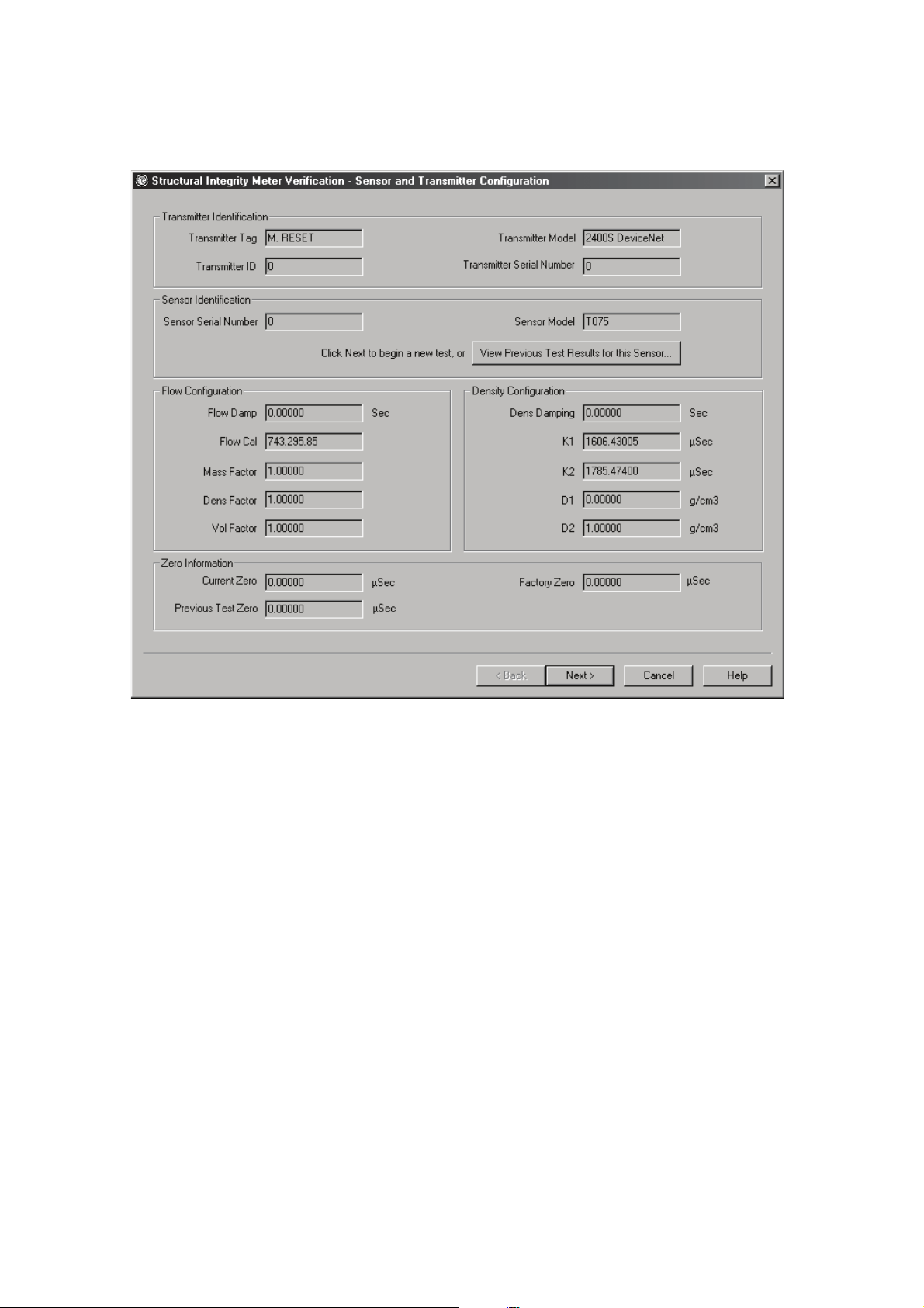
Meter Verification
Figure 6-1 Meter Verification - Sensor and Transmitter Configuration panel
ProLink II records the results of previous tests in a meter verification test database stored on the
computer on which ProLink II is installed. If you have already run one or more tests on this meter,
you can review those previous test results before starting a new test by clicking
Results for this Sensor ...
. This will open the Test Results panel shown in Figure 6-4.
View Previous Test
Notes: Test records are identified in the meter verification test database by transmitter/sensor pair. For
the transmitter, the identifier is the HART Unique ID, which is entered in the transmitter memory at
the factory. For the sensor, the identifier is the sensor serial number stored in the transmitter memory.
Previous test results for the meter will be available only if the pairing of these two identifiers is
identical. Therefore, before you run the first test on a meter, make sure that the sensor serial number
displayed in the Sensor Identification box matches the sensor serial number on the sensor calibration
tag. If necessary, enter the sensor serial number in the Sensor panel of the Configuration window.
Previous test results are stored on the computer on which ProLink II is installed. If you performed
meter verification tests on the same meter from a different computer or from the meter display, the
results of these tests will not be visible.
The Structural Integrity meter verification method is not directly affected by any of the parameters
displayed in the Flow Configuration, Density Configuration and Zero Information boxes. However,
because any modification of these parameters can have an impact on the meter accuracy, this
information can be useful when reviewing meter verification test results to decide if the meter’s
accuracy meets factory specifications.
Once you have reviewed the meter information, click
Next.
68 ProLink® II Software for Micro Motion® Transmitters
Page 75

Meter Verification
6.2.2 Second panel: Test Definition
The Test Definition panel is shown in Figure 6-2.
Figure 6-2 Meter Verification - Test Definition panel
Meter Verification Transmitter TerminalsData LoggerTransmitter Configuration
This panel allows you to enter metadata about each test for auditing purposes. This metadata will be
saved with the test results and will also appear on the test report which will be generated at the end of
the test.
Notes: The metadata fields are optional. You will be able to run the meter verification test even if
these fields are left blank.
If you save the test results at the end of the meter verification procedure, the information entered here
will be automatically entered in this panel the next time you run a test on the same meter.
If you want to specify the test fluid, you can select one of the fluids listed in the Test Fluid drop-down
menu, or you can type the name of the test fluid. If you enter a new name, it will be saved in the
ProLink II meter verification database with the test results, and it will be available for selection in the
drop-down list the next time you run a test.
Note: The meter verification procedure can be performed on any process fluid. It is not necessary to
use the same test fluid for each test.
Installation and Use Manual 69
Page 76

Meter Verification
Specification Uncertainty Limit
The result of the meter verification test will be a percent uncertainty of normalized tube stiffness. The
default limit for this uncertainty is ±4.0%. This limit is stored in the transmitter, and can be changed
with ProLink II if necessary by clicking the arrow in the
selecting a value between 0.1 and 5 %. For most installations, it is advisable to leave the test limits at
the default value.
During meter commissioning, Micro Motion recommends performing meter verification several times
over a range of process conditions. This will establish a baseline for how widely the verification
measurement varies under normal circumstances. The range of process conditions should include
expected temperature, pressure, density, and flow rate variations. The default stiffness specification
uncertainty limit of ±4.0% should avoid false Fail results over the entire range of specified process
conditions. If the process variation observed during your meter commissioning is much different than
4%, you may adjust the specification limit to match your process variation. In general, to avoid false
Fail results, make sure that the specification limits are set to a value around twice the variation due to
the range of normal process conditions.
Once you have entered the necessary information and checked the uncertainty limit, click on
6.2.3 Third panel: Start
The Start panel, shown in Figure 6-3, allows you to initiate and monitor the meter verification
process.
Specification Uncertainty Limit box and
Next.
Figure 6-3 Meter Verification - Start panel
70 ProLink® II Software for Micro Motion® Transmitters
Page 77

Meter Verification
Sensor Operating Conditions
Meter verification is not affected by current process values. However, during the test, process
conditions must be stable. To maximize stability:
• Maintain a constant temperature and pressure.
• Avoid changes to fluid composition (e.g., two-phase flow, settling, etc.).
• Maintain a constant flow. For higher test certainty, reduce or stop flow.
If stability varies outside test limits, the meter verification procedure will be aborted. If this happens,
verify the stability of the process and retry the test.
Notes: If you want the external pressure value displayed in this panel to reflect actual line pressure,
you will need to set up polling of an external pressure measurement device for updated pressure
values. To set up pressure polling, see Section 5.8. Note that if a static pressure value is specified in
the Pressure panel of the Configuration window, it will be displayed here.
Once the test is started, the mass flow, volume flow and density values displayed on this panel will be
fixed and will not be updated for the duration of the test. The temperature and external pressure
values will continue to be updated throughout the test.
Configuration Details
The result of the Structural Integrity meter verification method is not directly affected by changes in
meter configuration or zero value. However, meter accuracy can be affected by changes of certain
configuration parameters or a by a change of the zero value. These indicators show whether the
transmitter's configuration and zero have changed since the last meter verification test. They are green
if configuration and zero are unchanged, and red otherwise. If an indicator is red, you can find out
more information about the changes by clicking the
Details... button next to the indicator. This
information can be useful when reviewing meter verification test results to decide if the meter’s
accuracy meets factory specifications.
Note: The status of these two indicators has no impact on the meter verification procedure. You will
be able to run the test even if these indicators are red.
Meter Verification
When you are ready to start the test, click
Start Meter Verification. ProLink II displays the following
dialog box, which asks you to fix the outputs at either the configured fault levels or the last measured
value. Output levels, as well as mass flow, volume flow and density values reported via digital
communication, will remain fixed for the duration of the test.
Meter Verification Transmitter TerminalsData LoggerTransmitter Configuration
To start meter verification:
• with outputs fixed at their configured fault levels, click
• with outputs fixed at the last measured value, click
Fault Configuration.
Hold Last Value.
A dialog box will appear to warn you that process measurement will be interrupted for the duration of
the test and to ask you if you wish to continue. Ensure that the process will be able to handle the
measurement interruption, then click
Installation and Use Manual 71
OK to start the test.
Page 78

Meter Verification
The test takes approximately four minutes to complete. During the test:
• The indicator at the bottom of the panel turns yellow and the monitor bar shows the progress of
• If a problem occurs during the test, the test will be aborted. The indicator will turn red and a
• If you need to stop the procedure before the end of the test, click
At the end of the test, a dialog box describing the result of the test will appear:
• Meter passed verification—The test result is within the range defined by the current
• Meter failed verification—The test result is not within the range defined by the current
The
Meter Verification Counter displays the total number of meter verification tests that have been
performed on this transmitter.
• The counter is incremented each time a meter verification test is completed, whether the test
• The counter will not be incremented if the test is aborted, either automatically or by the user.
CAUTION
Transmitter outputs and process values reported through digital
communication will remain fixed at either the configured fault levels or the
last measured value for the duration of the test.
To ensure the safety of your process:
• Disable all control loops for the duration of the procedure.
• Ensure that any data reported during this period is handled appropriately.
the meter verification procedure.
popup window will indicate why the test could not be completed. Correct the problem before
restarting the test.
Abort Meter Verification.
The test will stop immediately, and all the data collected for this test will be discarded.
Specification Uncertainty Limit parameter. If transmitter zero and configuration match factory
values, the sensor will meet factory specifications for flow and density measurement. It is
expected that the meter will pass meter verification every time the test is run. Click
the popup window, then click
Next to go to the next panel.
Specification Uncertainty Limit parameter.
- Micro Motion recommends that you immediately re-run the meter verification test. To do
so, click
Yes to close the dialog box and automatically start a new test. If the meter passes
the second test, the first Fail result can be ignored. If the meter fails the second test, the
flow tubes may be damaged. Use the knowledge of your process to consider the type of
damage and determine the appropriate action. These actions might include removing the
meter from service and physically inspecting the tubes. At minimum, you should perform
a flow validation and a density calibration. For more information on these procedures,
refer to the transmitter manual.
- If you don’t want to re-run the test, click
No to close the dialog box, then click Next to go
to the next panel.
passed of failed.
OK to close
Note: Because this counter resides in the transmitter memory and not in the ProLink II meter
verification test database, it will also be incremented when a meter verification test is run from the
meter display or from another computer. Therefore, if meter verification tests have been conducted
from the display or from another computer, the number of tests displayed here will be different from
the number of tests displayed in the graph in the test results panel.
72 ProLink® II Software for Micro Motion® Transmitters
Page 79

Meter Verification
6.2.4 Fourth panel: Test Results
The Test Results panel, shown in Figure 6-4, summarizes the result of the meter verification test.
Figure 6-4 Meter Verification - Test Results panel
Meter Verification Transmitter TerminalsData LoggerTransmitter Configuration
The indicator located at the top of the panel indicates the test result. It is green if the meter passed the
test and red if it failed.
In addition to the pass/fail indicator, ProLink II shows the changes in tube stiffness on a graph. This
allows you to see not only whether the meter is operating within specification, but also where the
results fall within the specified limits. For each test, the results are shown as two data points
corresponding to the stiffness at the inlet and at the outlet of the flow tubes.
This graph also shows the results of previous tests performed on this meter. The rightmost data points
are the most recent. This history lets you see how your meter is trending over time, which can be a
useful way to detect meter problems before they become severe. The trending of both the inlet and the
outlet points over several tests can also help determine whether changes to the flow tubes are localized
or generalized.
Note: Historical data are stored on the computer on which ProLink II is installed. If you performed
meter verification tests on the same meter from a different computer or from the meter display, the
historical data for these tests will not be visible.
Installation and Use Manual 73
Page 80

Meter Verification
You can manipulate the graphed data in various ways by double-clicking the graph to open a
configuration dialog or by right-clicking on it to open a contextual menu. From there, you can also
export the graph in a number of formats (including “to printer”) by clicking
When you have finished reviewing the test results:
Export.
• To save the data to the ProLink II database, click
• To exit without saving, click
Cancel. The current test data will be discarded and the meter
verification window will close.
6.2.5 Fifth panel: Report
The last panel, shown in Figure 6-5, displays a detailed report of the current test results.
Figure 6-5 Meter Verification - Report panel
Next.
74 ProLink® II Software for Micro Motion® Transmitters
Page 81

Meter Verification
This report contains all the information supplied in the Test Definition panel, as well as information
about the meter's configuration and operating conditions during the test. It indicates:
• If the meter has passed or failed the meter verification test
• If the Configuration Changed indicator was activated
• If the Zero Changed indicator was activated
• The number of meter verifications that have been performed on this meter
In addition, the graph showing the current and previous test results is included.
From this panel, you can:
• Print the report
• Save the report to a file
• Save test results to the meter verification test database
• Discard test results
To print the report, click
computer's system settings.
To save the report, click
and location that you specify.
Print Report. The report is sent to the default printer defined in your
Save Report. It will be saved to disk as an HTML file, using the file name
Meter Verification Transmitter TerminalsData LoggerTransmitter Configuration
Note: The Save Report button allows you to save the displayed report, but it does not save the test
data. To save the test data, you must click Finish as described below.
To save test results to the meter verification test database and close the Meter Verification dialog,
click
Finish. The test results will be saved in a database on the computer on which ProLink II is
installed.
To discard current test results and close the Meter Verification dialog, click
Cancel. The results of the
current test will be discarded and will not appear on the graph in subsequent meter verification tests.
Installation and Use Manual 75
Page 82

76 ProLink® II Software for Micro Motion® Transmitters
Page 83

Chapter 7
Data Logger
7.1 Overview
The Data Logger tool allows periodic logging of user-selected meter data, including process variables,
diagnostic variables, and output levels. Data logged via Data Logger can be viewed or imported into
external programs such as spreadsheets for further analysis.
7.2 Using Data Logger
The Data Logger screen is shown in Figure 7-1.
To set up data logging, you must define the log file, specify the type of data to be logged and the
frequency of data points, and start the logging process.
7.2.1 Defining the log file
To define the log file:
Meter Verification Transmitter TerminalsData LoggerTransmitter Configuration
1. Click the
•
•
•
2. Enter the name for the log in the
3. Click the
saved.
4. Specify
Note: If you are using HART protocol, be careful not to set Update Rate too high. On HART/Bell 202,
Micro Motion suggests logging as few variables as possible, and setting the update rate to 5–10
seconds (50000–10000 msec). The same restrictions apply to HART/RS485 at lower baud rates,
especially 1200 baud.
5. Use the
log.
6. Use the
• To log only when variable values change, select
• To log data continuously irrespective of whether process data change or not, select
File Type radio button to specify the log file format. Options include:
.txt – standard text file
.csv – comma separated values, for import into standard spreadsheets
.dif – data interchange format, for import into standard spreadsheets
Filename textbox.
... button to bring up a file browser and specify the location where the log will be
Update Rate and unit to control the frequency of data points in the log.
Status Error Logging checkbox to specify whether status errors will be written to the
Log On radio buttons to specify how the data will be logged:
Device Data Change. An initial value
will be logged for each variable as soon as the logging is started, but subsequent data
points will be logged only if the values change. If process variables are stable, no data will
be recorded.
Time
Interval
Rate
. Data will be logged continuously according to the time interval set in the Update
textbox.
Installation and Use Manual 77
Page 84

Data Logger
Note: The log file can become very large if you choose Time Interval and log for a long period of
time. Be sure to set the Update Rate accordingly.
Figure 7-1 Data Logger
7.2.2 Specifying log contents
To specify the types of data to be included in the log:
1. Click on the
2. Double-click on the desired variable in the list, or highlight the variable and click
3. To remove a variable from the
4. To remove all variables from the
5. While
textbox, then pressing
Process Vars, Diagnostics, Output Vars, or All Vars tab.
Add.
Current Log list, highlight its name and click Remove.
Current Log list, click the Clear All button.
Data Logger is running, you can add a note to the log by entering the note in the
Add Note. The note is added to the current end of the log; subsequent
data points will be added after the note.
78 ProLink® II Software for Micro Motion® Transmitters
Page 85

Data Logger
7.2.3 Starting and stopping the logging function
You can start and stop
You can combine these methods; e.g., you can start the logging function manually and set a stop time
to stop it automatically.
Data Logger either manually or automatically.
• To start and stop
area of the
•To start
Enable checkbox.
the
•To stop
Enable checkbox.
the
Data Logger window.
Data Logger automatically, enter the date and time in the Start time fields, then check
Data Logger automatically, enter the date and time in the Stop time fields, then check
Data Logger manually, use the Start and Stop buttons in the Current Log
While
Data Logger is running, the Log Statistics fields in the Data Logger window are
continuously updated.
Note: The
Data Logger window must be open for logging to occur. If you close the Data Logger
window, logging is stopped automatically.
7.2.4 Data Logger tools
Data Logger provides several tools for ease of use:
• You can move specific variables to the
variables to the
Diagnostics, Output Vars, or All Vars tab, then click Add to Favorites.
Current Log list. To do this, highlight a variable in the Process Vars,
• You can save specific log configurations. To do this, click
Favorites tab, and work from the Favorites tab to add
Save Settings and specify a file
name and location.
• You can reload specific log configurations. To do this, click
Load Settings and specify the file
name and location of the log configuration file.
• You can save the current transmitter configuration to your PC. To do this, click
Transmitter Configuration
and specify a file name and location.
Save
Note: The format of this configuration file matches the format of the configuration file saved via the
File menu. They can be used interchangeably.
Meter Verification Transmitter TerminalsData LoggerTransmitter Configuration
Installation and Use Manual 79
Page 86

80 ProLink® II Software for Micro Motion® Transmitters
Page 87

Appendix A
Transmitter Terminal Reference
A.1 Overview
This appendix provides diagrams of the transmitter terminals that can be used for a ProLink II
connection. The following transmitters are shown:
• RFT9739, RFT9712, and IFT9701/9703 transmitters (see Figure A-1)
• Model 1500/2500 transmitters (see Figure A-2)
• Model 1700/2700 transmitters (see Figure A-3)
• Model 2400S transmitters with analog outputs (see Figure A-4)
• Model 2400S transmitters with DeviceNet I/O (see Figure A-5)
• Model 2400S transmitters with PROFIBUS-DP I/O (see Figure A-6)
• Series 3000 transmitters (see Figure A-7)
• Core processor and Enhanced core processor (see Figure A-8)
Meter Verification Transmitter TerminalsData LoggerTransmitter Configuration
• MVD Direct Connect I.S. barrier (see Figure A-9)
For detailed instructions on connecting ProLink II to your transmitter, see Chapter 2.
Installation and Use Manual 81
Page 88

Transmitter Terminal Reference
)
A.2 Transmitter terminal diagrams
Figure A-1 RFT9739, RFT9712, and IFT9701/9793 transmitters
RFT9739 field-mount
17 (PV+) 18 (PV –)
RFT9712
17 (+) 16 (–)
22 (RS-485/B) 21 (RS-485/A)
HART/Bell-202
hookups
27 (RS-485/A)26 (RS-485/B)
HART/Bell-202 hookups
HART jack
RFT9739 rack-mount
CN2
D22
(RS-485/A)
D30
(PV–)
IFT9701 / IFT9703
Z22
(RS-485/B
Z30
(PV+)
4–20mA
Figure A-2 Model 1500/2500 transmitters
21 (PV+) 22 (PV–)
33
(RS-485/A)
82 ProLink® II Software for Micro Motion® Transmitters
34
(RS-485/B)
Page 89

Transmitter Terminal Reference
Figure A-3 Model 1700/2700 transmitters
2 (–)
5
(RS-485/A)
6
(RS-485/B)
7
Service port
(RS-485/B)
Note: Terminals 5 and 6 used for communications only by
transmitters with the analog outputs option board.
Figure A-4 Model 2400S transmitters with analog outputs
User interface
(with display, cover removed)
1 (+)
8
Service port
(RS-485/A)
Meter Verification Transmitter TerminalsData LoggerTransmitter Configuration
Outputs wiring compartment
(user interface removed)
HART clips
HART clips
Service port
(RS-485/B)
Service port
(RS-485/A)
1 (+)
2 (–)
Note: The user interface shown here is equipped with a display. On models without a display, the
HART clips and service port clips are located in the same position on the user interface.
Installation and Use Manual 83
Page 90

Transmitter Terminal Reference
Figure A-5 Model 2400S transmitters with DeviceNet I/O
With display Without display
3.237
G/S
Service port
(RS-485/B)
Service port
(RS-485/A)
Figure A-6 Model 2400S transmitters with PROFIBUS-DP I/O
With display Without display
Service port
(RS-485/B)
Service port
(RS-485/A)
Service port
(RS-485/B)
Service port
(RS-485/A)
84 ProLink® II Software for Micro Motion® Transmitters
Service port
(RS-485/A)
Service port
(RS-485/B)
Page 91

Transmitter Terminal Reference
Figure A-7 Series 3000 transmitters
Series 3000 panel-mount
Input/output wiring terminals
Card for Model 3300 or 3500 with
screw-type or solder-tail terminals
Series 3000 rack-mount Series 3000 field-mount
Input/output wiring terminals
Label for Model 3300 or 3500
with I/O cables
Input/output wiring terminals
Label for Model 3350
or 3700
Meter Verification Transmitter TerminalsData LoggerTransmitter Configuration
Installation and Use Manual 85
Page 92

Transmitter Terminal Reference
Figure A-8 Core processor
Standard Enhanced
4
(RS-485/B)
3
(RS-485/A)
Figure A-9 MVD Direct Connect I.S. barrier
3
(RS-485/A)
14
(RS-485/B)
4
(RS-485/B)
Non-I.S. terminals
13
(RS-485/A)
86 ProLink® II Software for Micro Motion® Transmitters
Page 93

Appendix B
Configuring the Discrete Batch Application
B.1 About this appendix
This appendix explains how to configure the discrete batch application, and provides basic
information on batch operation.
Note: For more detailed information on operating the discrete batch application, see the
Series 3000 MVD transmitter manual.
Note: The discrete batch application is an optional feature, and may not be installed on your
transmitter. To verify that it is installed, use the Installed Options item on the ProLink II View menu.
Note: For full ProLink II functionality for the discrete batch application, you must connect to the
transmitter using a Modbus connection. If you are using a HART connection, only limited
functionality is available.
Changing configuration can affect transmitter operation, including batching.
Changes made to discrete batch configuration while a batch is running do not take
effect until the batch is ended. Changes made to other configuration parameters
may affect batching. To ensure correct batching, do not make any configuration
changes while a batch is in progress.
B.2 About discrete batching
Discrete batching is used to start flow, then stop flow automatically when the target amount of process
fluid has flowed through the sensor. During a batch, flow may be stopped and resumed. A batch may
also be ended before the target is reached.
B.3 Discrete batch configuration
Index Discrete Batch
CAUTION
To configure batching:
1. Open the ProLink II
2. Click on the
a. Configure flow source (see Section B.3.1) and click
b. Configure control options (see Section B.3.2) and click
c. Configure one or more presets, if desired (see Section B.3.3) and click
Installation and Use Manual 87
Discrete Batch tab. The panel shown in Figure B-1 is displayed. In this panel:
Configuration window.
Apply.
Apply.
Apply.
Page 94

Configuring the Discrete Batch Application
Figure B-1 Discrete batch configuration panel
3. Click on the
Discrete IO or Discrete Output tab. A panel similar to Figure B-2 is displayed.
In this panel:
a. Configure the required discrete outputs.
- For 1-stage operation, you must configure one discrete output. This output must
control either the pump or the primary valve, as appropriate to your application. This
discrete output is required.
- For 2-stage operation, you must configure either two or three discrete outputs: one to
control the primary valve (required), one to control the secondary valve (required),
and one to control the pump (optional; only if required by your installation).
You must configure the discrete outputs that are listed as required, whether or not your
installation uses them (for example, you may start and stop the pump manually). You will
not be able to start a batch until the required discrete outputs have been configured.
b. Click
88 ProLink® II Software for Micro Motion® Transmitters
Apply.
Page 95
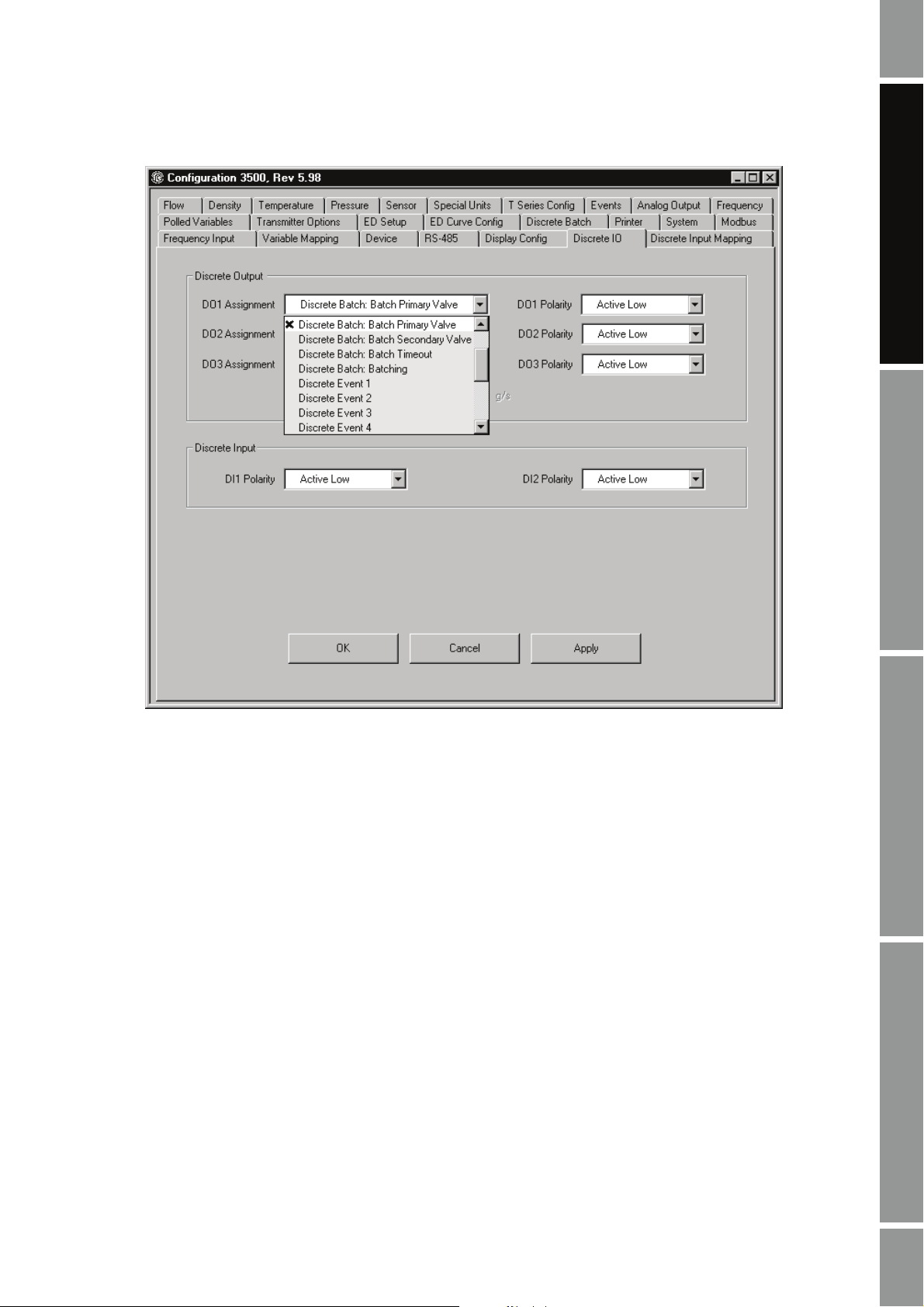
Configuring the Discrete Batch Application
Figure B-2 Discrete IO panel
Index Discrete Batch Index Discrete Batch Index Discrete Batch Index Discrete Batch
4. If desired, you can assign a batch control function to a discrete input or discrete event. See
Section B.3.4.
5. If you enabled the Batch AOC control option, you should perform batch AOC (automatic
overshoot compensation) calibration. Batch AOC is used to minimize the amount of overshoot
per batch. See Section B.5.
6. You may optionally configure the batch ticket and ticket printing. Printer and ticket options are
displayed on the
Printer panel of the Configuration window. For more information on printer
and ticket setup, see the Series 3000 transmitter manual.
B.3.1 Flow source
The flow source specifies the flow variable that will be used for batch measurement. Select one of the
flow sources defined in Table B-1.
Installation and Use Manual 89
Page 96

Configuring the Discrete Batch Application
Tabl e B-1 Flow sources
Flow source Default Description
None None • Batch controller is disabled.
• START button will not appear on display.
Frequency input • Frequency input from a Micro Motion IFT9701 or RFT9739 transmitter
• Frequency input from a pulse output device
Mass flow rate Mass flow rate from Series 3000 transmitter
Volume flow rate Volume flow rate from Series 3000 transmitter
ED std vol flow rate • Standard volume flow rate at reference temperature
ED mass flow rate • Net mass flow rate
ED vol flow rate • Net volume flow rate at reference temperature
API temperaturecorrected volume
flow
• Standard volume flow is available only if the enhanced density application software
is installed and configured to indicate standard volume flow.
• Net mass flow is available only if the enhanced density application software is
installed and configured to indicate net mass flow.
• Net volume flow is available only if the enhanced density application software is
installed and configured to indicate net volume flow.
• Volume flow adjusted by the calculated volume correction factor
• Available only if the petroleum measurement application is installed and enabled.
B.3.2 Control options
The batch control options are used to manage the batch process. Control options are listed and defined
in Table B-2.
Note: Control options apply to all batch presets.
Tabl e B-2 Control options
Setting Default Description
Enable batch Yes • Select Yes to enable the discrete batch application.
• Select No to disable the discrete batch application. The operation mode will
default to the process monitor.
Count up Yes • If set to Yes, the total displayed on screen increases from zero to the target
Enable AOC Yes • Select Yes to enable Automatic Overshoot Compensation (AOC).
Lockout target No • If set to Yes, the operator cannot change the current target from the batch
value.
• If set to No, the total displayed on screen decreases from the target value to
zero
• The setting of the Count up control option affects only the quantity displayed
on screen. It does not affect configuration of presets.
• If the custody transter application is installed, Count up is set to Yes and
cannot be changed.
• When batch AOC is enabled and batch AOC calibration has been performed,
the batch controller compensates for the time required to close the valve.
• If Enable AOC is set to Yes, batch AOC calibration is required to provide data
for the compensation process. To perform batch AOC calibration, see
Section B.5.
operation screen or the ProLink II Batcher Control panel.
• If set to No, the operator can change the batch target when a batch is not
running.
90 ProLink® II Software for Micro Motion® Transmitters
Page 97

Configuring the Discrete Batch Application
Tabl e B-2 Control options continued
Setting Default Description
Reset on start No • If set to Yes, the batch totalizer resets when the operator starts the batch.
Enable end
warning
Enable overrun No • Select Yes to enable overrun indication.
Ignore source
alarms
No-flow timeout 10.00000 Sec • The time out period specifies how long the batch controller will wait before
Number of stages 1 Stage Specify 1 Stage or 2 Stage. See the discussion in Section .
Number of
decimals
Maximum target 1.0000E9 kg If Lockout target is set to No, enter the maximum target that the operator will be
Alarm timeout 1.00000 Min This parameter is applicable only if Ignore source alarms is set to Yes.
Configure presets by% Target Select % Target or Quantity.
No • Select Yes to enable the end warning.
No A source alarm is any fault-level alarm. If Ignore source alarms:
1 • Enter a value of 0 to 5.
• If set to No, the operator must reset the batch before starting a new batch.
Several methods are available for resetting the batch. See Section B.3.4.
• If the custody transter application is installed, Reset on start is set to No and
cannot be changed.
• When end warning is enabled and an end warning value has been entered for
the selected preset, a discrete output can be configured to indicate the end
warning.
• End warning is a status indicator only, and does not affect valve operation.
• End warning will remain active until batch completion.
• When overrun is enabled and an overrun value has been entered for the
selected preset, the batch controller produces an overrun alarm when the
batch total exceeds the target by more than the programmed overrun amount.
• Overrun can be assigned to a discrete output, using the Discrete IO panel in
the ProLink II Configuration window.
• Is set to Yes, the batch will not stop for the duration of the alarm timeout.
• Is set to No, the batch is stopped as soon as the alarm condition occurs.
If the custody transter application is installed, Ignore source alarms is set to No
and cannot be changed.
posting an alarm if flow stops or the batch totalizer is inhibited while a batch is
running.
• Enter a value of 0.0 to 300.0.
• Time out is disabled if set to 0.0 seconds.
• Time out can be assigned to a discrete output, using the Discrete IO panel in
the ProLink II Configuration window.
• This value specifies the number of digits to the right of the decimal point on the
operation screen.
allowed to set in the batch operation mode.
• Enter the number of minutes, from 1 to 20, for which source alarms will be
ignored.
• If the alarm condition is present when the alarm timeout expires, the current
batch is stopped.
• If set to % Target, Open primary, Open secondary, Close primary, and End
warning values are configured as a percentage of the batch target.
• If set to Quantity, Open primary and Open secondary are each configured as a
quantity at which the valve should open; Close primary and End warning
values are each configured as a quantity that is subtracted from the batch
target.
Index Discrete Batch Index Discrete Batch Index Discrete Batch Index Discrete Batch
Installation and Use Manual 91
Page 98

Configuring the Discrete Batch Application
One-stage versus two-stage batching
If
Number of stages is set to 1, a single pump or valve is used to control the batch. When the batch is
started, the pump starts or the valve opens; at the configured target, the pump stops or the valve
closes.
Open primary, Open secondary, and Close primary values are not required when
configuring the preset (see Section B.3.3).
If
Number of stages is set to 2, two valves are used to control the batch, and the following
requirements apply when configuring the preset:
• Both
Open primary and Open secondary must be configured.
• Either
•
Open primary or Open secondary must be set to 0. Both may be set to 0 if desired.
Close primary must be configured.
B.3.3 Configure presets
You can configure up to six batch presets. Preset 1 cannot be disabled, but you can change its
configuration.
Table B-3 defines the options for configuring presets. To configure a preset, first select the preset to be
configured, then define its parameters.
Tabl e B-3 Preset parameters
Setting Default Description
Name • Preset 1
Enable preset • Yes for preset 1
Open primary
Open
secondary
Close primary
End warning
(1)
• Preset 2
• Preset 3
•Preset 4
• Preset 5
• Preset 6
• No for presets 2-6
(1)
0.00% of target or
0.0 kg quantity
0.00% of target or
0.0 kg quantity
(1)
80.00% of target or
0.0 kg quantity
(2)
80.00% of target or
0.0 kg quantity
• Enter the name that will appear on operation screens and in preset selection
menus.
• A maximum of 22 characters can be stored.
• If set to Yes, the batch preset can be selected for use. See Section B.4.
• If set to No, the batch preset is disabled and cannot be selected.
• Preset 1 cannot be disabled.
• Enter the quantity or the percent of the target at which the primary valve will
open. See the examples later in this section.
• Either Open primary or Open secondary must be set to 0. If one of these
parameters is set to a non-zero value, the other is set to 0 automatically
• Before a batch can be started, the primary valve must be assigned to a
discrete output. See Section B.3, Step 3.
• Enter the quantity or the percent of the target at which the secondary valve
will open. See the examples later in this section.
• Either Open primary or Open secondary must be set to 0. If one of these
parameters is set to a non-zero value, the other is set to 0 automatically
• Before a batch can be started, the secondary valve must be assigned to a
discrete output. See Section B.3, Step 3.
• Enter the quantity subtracted from the target, or the percent of the target, at
which the primary valve will close. See the examples later in this section.
• The secondary valve always closes when the target is achieved.
• Before a batch can be started, the primary valve must be assigned to a
discrete output. See Section B.3, Step 3.
• If End warning is enabled as a control option, enter the quantity subtracted
from the target, or the percent of the target, at which the end warning will
occur. See the examples later in this section.
• End warning can be assigned to a discrete output, using the Discrete IO
panel in the ProLink II Configuration window.
92 ProLink® II Software for Micro Motion® Transmitters
Page 99

Configuring the Discrete Batch Application
Tabl e B-3 Preset parameters continued
Setting Default Description
Density curves None If an enhanced density variable is selected as the flow source, you must select
Overrun
Ta rg e t
(1) This parameter is configurable only if Number of stages was set to 2.
(2) This parameter is configurable only if Enable end warning was set to Yes.
(3) This parameter is configurable only if Enable overrun was set to Yes.
(4) A non-zero value must be configured for Target before a batch can be started.
(3)
(4)
0.0 kg • If Overrun is enabled as a control option, enter the amount over the target
0.0 kg Enter the total at which the batch will be completed.
a density curve that will apply to this preset. The batch total will be based on
the density curve for that variable.
value at which batch overrun will be indicated. For example, if the target is
250 kilograms and overrun should be indicated at 280 kilograms, enter 30.
• Overrun can be assigned to a discrete output, using the Discrete IO panel in
the ProLink II Configuration window.
Batch preset examples
The following examples describe the batch processing sequence for two different batch preset
configurations.
Note: For a detailed presentation of batch processing sequences, including how the
RESUME functions affect processing, see the Series 3000 MVD transmitter manual.
Example 1
Index Discrete Batch Index Discrete Batch Index Discrete Batch Index Discrete Batch
STOP and
Configure presets by quantity under the following conditions:
• The target is 200 kilograms
• The primary valve opens at the start of the batch and closes when
180 kilograms have been delivered
• The secondary valve opens when 100 kilograms have been
delivered
• The end warning occurs when 160 kilograms have been delivered
Close primary 200 kilograms 180 kilograms 20=–=
Open secondary 100 kilograms=
End warning 200 kilograms 160 kilograms– 40==
Installation and Use Manual 93
Page 100

Configuring the Discrete Batch Application
Example 2
Configure presets by percent of target under the following conditions:
• The target is 200 kilograms
• The primary valve opens at the start of the batch and closes when
180 kilograms have been delivered
• The secondary valve opens when 100 kilograms have been
delivered
• The end warning occurs when 160 kilograms have been delivered
Close primary
Since 0.90 equals 90%, enter a close primary value of 90.
Open secondary
Since 0.50 equals 50%, enter an open secondary value of 50.
End warning
Since 0.80 equals 80%, enter an end warning value of 80.
180 kilograms
-------------------------------------==
200 kilograms
100 kilograms
-------------------------------------==
200 kilograms
160 kilograms
-------------------------------------==
200 kilograms
0.90
0.50
0.80
B.3.4 Batch control methods
Batch control functions can be performed in three ways:
• By using the function buttons on the transmitter display (see the Series 3000 transmitter
manual), or in the ProLink II
Batcher Control window (see Section B.4)
• By assigning a discrete input to a batch control function
• By assigning a discrete event to a batch control function
If a discrete input or discrete event is assigned to a batch control function, the function is triggered
when the discrete input or discrete event is in an On state.
Table B-4 lists the batch control functions. To assign a discrete input or discrete event to trigger a
batch function:
1. Open the ProLink II
Configuration window and click on the Discrete Input Mapping tab.
The panel shown in Figure B-3 is displayed.
2. Select the batch function to be triggered. Batch functions are listed and defined in Table B-4.
3. Specify the method which will be used to trigger the batch function: Discrete Event 1–5 or
Discrete Input 1–2.
Note: You can assign one or more actions to a single discrete input or discrete event. All assigned
actions will be performed, as allowed by the configuration and current state of the discrete batch
application.
94 ProLink® II Software for Micro Motion® Transmitters
 Loading...