

Page 1
A technical manual from the experts
in Business-Critical Continuity
™
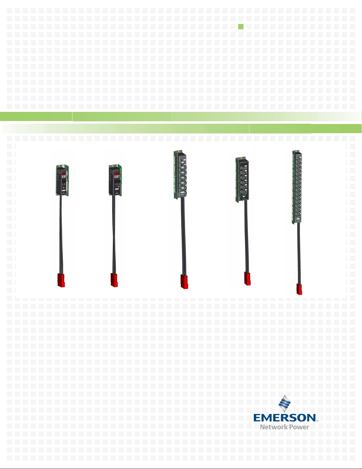
NetSure™ RDB Series
Installation and User Manual — Plug-n-Play 48V Rack Distribution
Section 6041 (Issue AG, January 21, 2013)
Page 2

Business-Critical Continuity™, Emerson Network Power, and the Emerso n Net wo rk
Power logo are trademarks and service marks of Emerson Electric Co.
NetSure™, NetSpan™, NetReach™, NetXtend™, and NetPerform™
are trademarks of Emerson Network Power, Energy Systems, North America, Inc.
All other trademarks are the property of their respective owners.
The products covered by this instruction manual are manufactured and/or
sold by Emerson Network Power, Energy Systems, North America, Inc.
The information contained in this document is subject to change without notice and may not be
suitable for all applications. While every precaution has been taken to ensure the accuracy and
completeness of this document, Emerson Network Power, Energy Systems, North America, Inc.
assumes no responsibility and disclaims all liability for damages resulting from use of this information
or for any errors or omissions. Refer to other local practices or building codes as applicable for the correct
methods, tools, and materials to be used in performing procedures not specifically described in this document.
This document is the property of Emerson Network Power, Energy Systems, North America, Inc.
and contains confidential and proprieta r y information owned by Emerson Network Power, Energy
Systems, North America, Inc. Any copying, use or disclosure of it without the written permission
of Emerson Network Power, Energy Systems, North America, Inc. is strictly prohibited.
Copyright
©
2013, Emerson Network Power, Energy Systems, North America, Inc.
All rights reserved throughout the world.
Page 3

TABLE OF CONTENTS
IMPORTANT SAFETY INSTRUCTIONS . . . . . . . . . . . . . . . . . . . . . . . . . . . . . . . . . . . . . . . . . . . . . . . .1
1.0 INSTALLATION
1.1 Shipment Inspection . . . . . . . . . . . . . . . . . . . . . . . . . . . . . . . . . . . . . . . . . . . . . . . . . . . . . . . . . 2
1.2 Installing the Rack PDU . . . . . . . . . . . . . . . . . . . . . . . . . . . . . . . . . . . . . . . . . . . . . . . . . . . . . . 2
1.2.1 Installing the Rack PDU Directly to a Rack Frame or Existing Mounting Bracket . . . . . . . . 2
1.2.2 Installing Rack PDUs to a Rack Frame using the Optional Mounting Bracket . . . . . . . . . . . . 2
2.0 ELECTRICAL CONNECTIONS
2.1 Connecting the Rack PDU DC Input. . . . . . . . . . . . . . . . . . . . . . . . . . . . . . . . . . . . . . . . . . . . . 4
2.2 Connecting the Rack PDU’s DC Output to Customer Equipment . . . . . . . . . . . . . . . . . . . . . 4
2.3 Connecting External Circuit Breaker Alarms . . . . . . . . . . . . . . . . . . . . . . . . . . . . . . . . . . . . . 5
3.0 SPECIFICATIONS AND TECHNICAL DATA
3.1 Conformity and Standards. . . . . . . . . . . . . . . . . . . . . . . . . . . . . . . . . . . . . . . . . . . . . . . . . . . . . 6
3.2 Environmental Characteristics . . . . . . . . . . . . . . . . . . . . . . . . . . . . . . . . . . . . . . . . . . . . . . . . . 6
3.3 Specifications . . . . . . . . . . . . . . . . . . . . . . . . . . . . . . . . . . . . . . . . . . . . . . . . . . . . . . . . . . . . . . . 6
3.4 Dimensions . . . . . . . . . . . . . . . . . . . . . . . . . . . . . . . . . . . . . . . . . . . . . . . . . . . . . . . . . . . . . . . . . 7
3.4.1 NetSure™ RDB L6, P/Ns 547692, 547693, 547499 . . . . . . . . . . . . . . . . . . . . . . . . . . . . . . . . . . . 7
3.4.2 NetSure
3.4.3 NetSure
3.4.4 NetSure
3.4.5 NetSure
3.4.6 NetSure
™
RDB L15, P/Ns 547694, 547695, 547615 . . . . . . . . . . . . . . . . . . . . . . . . . . . . . . . . . . 8
™
RDB M6, P/Ns 547696, 547697, 547503 . . . . . . . . . . . . . . . . . . . . . . . . . . . . . . . . . . 9
™
RDB H2, P/N 547500 . . . . . . . . . . . . . . . . . . . . . . . . . . . . . . . . . . . . . . . . . . . . . . . . 10
™
RDB H3, P/Ns 547698, 547699, 547501 . . . . . . . . . . . . . . . . . . . . . . . . . . . . . . . . . 11
™
RDB Mounting Bracket, P/N 547665. . . . . . . . . . . . . . . . . . . . . . . . . . . . . . . . . . . . 12
3.5 Input Quick Connect Kit . . . . . . . . . . . . . . . . . . . . . . . . . . . . . . . . . . . . . . . . . . . . . . . . . . . . . 13
3.6 Output Cable Assemblies. . . . . . . . . . . . . . . . . . . . . . . . . . . . . . . . . . . . . . . . . . . . . . . . . . . . . 13
3.6.1 P/N 547595, P/N 547613 and P/N 555654 . . . . . . . . . . . . . . . . . . . . . . . . . . . . . . . . . . . . . . . . . 13
3.6.2 Output Connector Kits (P/N 554878 and P/N 554944). . . . . . . . . . . . . . . . . . . . . . . . . . . . . . . 14
3.7 Replacement Circuit Breakers. . . . . . . . . . . . . . . . . . . . . . . . . . . . . . . . . . . . . . . . . . . . . . . . . 14
4.0 OPERATION
4.1 Connecting Power to the Loads . . . . . . . . . . . . . . . . . . . . . . . . . . . . . . . . . . . . . . . . . . . . . . . . 15
4.2 Removing Power from the Loads. . . . . . . . . . . . . . . . . . . . . . . . . . . . . . . . . . . . . . . . . . . . . . . 15
4.3 Alarms. . . . . . . . . . . . . . . . . . . . . . . . . . . . . . . . . . . . . . . . . . . . . . . . . . . . . . . . . . . . . . . . . . . . 15
4.3.1 Local Alarm Indicator . . . . . . . . . . . . . . . . . . . . . . . . . . . . . . . . . . . . . . . . . . . . . . . . . . . . . . . . 15
4.3.2 External Circuit Breaker Alarm . . . . . . . . . . . . . . . . . . . . . . . . . . . . . . . . . . . . . . . . . . . . . . . . 15
REVISION RECORD
i
Page 4

This Page Intentionally Left Blank
ii
Page 5

IMPORTANT SAFETY INSTRUCTIONS
SAVE THESE INSTRUCTIONS
WARNING
!
Please read and follow all safety information!
Failure to observe the safety information listed below may result in electric shock, fire
hazards, or serious injury.
Please safeguard this Installation and User Manual.
Intended Use
The NetSure™ RDB Rack PDU (Power Distribution Unit) is designed to deliver power to
information technology and telecommunication equipment.
Operate the Rack PDU in an indoor environment only within an ambient temperature range and a
relative humidity range as listed in 3.2 - Environmental Characteristics. Install the Rack PDU in
a clean environment, free of conductive contaminants, moisture, flammable liquids, gases and corrosive substances.
• Do not use the Rack PDU in moist environments. If the Rack PDU is exposed to moisture, immediately disconnect the Rack PDU from DC input power by opening the circuit breaker or removing
the fuse or breaker supplying DC input to the Rack PDU. Send the Rack PDU to the manufacturer for inspection.
• Do not use the Rack PDU for household applications.
Installation and Operation
Improper installation and operation may cause overheating and lead to increased fire hazard. It may also destroy the device and damage other connected systems.
• Installation and start-up must be performed by a qualified service engineer.
• Make sure that the total input current of the connected systems does not exceed the current rating specified on the rating plate of the Rack PDU.
Electrical Safety
Damaged Rack PDUs or connected cables increase the risk of electric shock or smoldering
fire.
• Check the unit for external signs of damage prior to start-up operation! Do not operate the device
if you detect any damage or other deficiencies.
• Only use the supplied DC input power cable.
Personal Safety
Careless handling increases the risk of electric shock.
• Never touch the outlets or the Rack PDU with wet or moist hands.
Service
Repairs should only be performed by qualified service technicians.
Unauthorized changes, modifications, or repairs of the device are performed at the owner’s risk and
will void all warranty claims.
• Do not open the Rack PDU.
• Please contact the nearest customer service center in case of malfunction! Damage and defects
must be repaired immediately.
• Always disconnect the unit from power before troubleshooting.
1
Page 6

1.0 INSTALLATION
The NetSure™ RDB Rack PDUs (Power Distribution Units) are designed to be installed on the left
and/or right rear frames of IT racks. They can be mounted directly to the rack or use Rack PDU
Mounting Kit P/N 547665. See 3.4 - Dimensions for hole dimensions.
1.1 Shipment Inspection
Unpack the shipping container, inspect all items for damage and verify that the shipment is complete
and undamaged. Report any damage to your local Emerson representative and the carrier.
1.2 Installing the Rack PDU
WARNING
!
Ensure proper grounding.
The Rack PDU’s "Ground Lead Bracket" must be ground bonded to the mounting bracket (if
used) or rack frame. The mounting bracket (if used) must be ground bonded to the rack frame.
The rack frame must be ground bonded to your site ground. This is typically accomplished
through the use of paint free areas and/or grounding washers used when mounting the
components.
1.2.1 Installing the Rack PDU Directly to a Rack Frame or Existing Mounting Bracket
Installation
Install the Rack PDU directly to the rack frame or existing mounting bracket as shown in Figure 1.
Note that the supplied "Ground Lead Bracket" is to be placed between the PDU and the rack frame or
existing mounting bracket as shown in Figure 1. Use the supplied 1/4-20 screws and 1/4-20 KEPS
nuts.
1.2.2 Installing Rack PDUs to a Rack Frame using the Optional Mounting Bracket
If using the Rack PDU Mounting Kit, install the Rack PDU mounting bracket to the left and/or right
rear frame of the rack using the appropriate hardware that fits to the cabinet that will be used.
Install the Rack PDUs to the Rack PDU mounting bracket that was previously installed on the frame
as shown in Figure 2. Note that the supplied "Ground Lead Bracket" is to be placed between the
PDU and the mounting bracket as shown in Figure 2.
2
Page 7
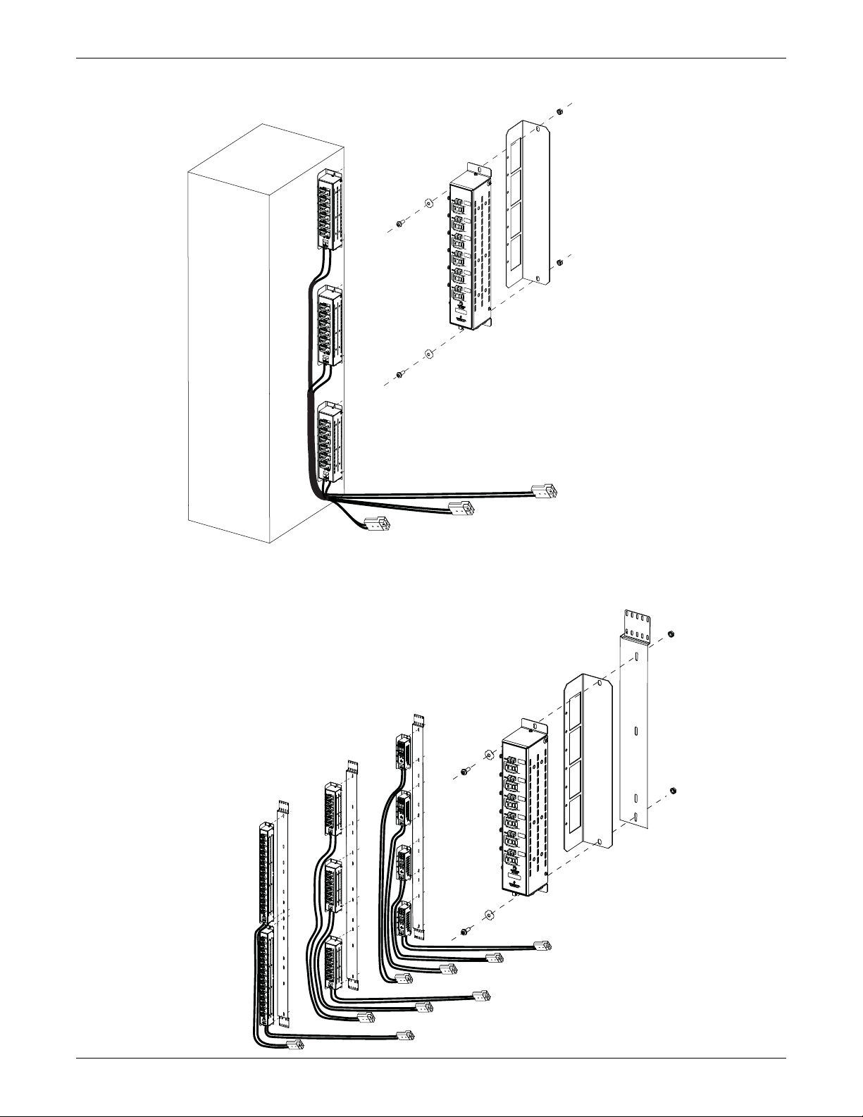
Figure 1 Mounting Rack PDUs Directly to Rack Frame
Rack PDUs can be mounted on either side.
Rack PDUs and Ground Lead Bracket can be
rotated 180 degrees (cables can exit at top or bottom).
PDU
Ground wires not shown
in illustration for clarity.
Ground
Lead
Bracket
Rear
Screw
Ground
Washer
Keps
Nut
Rack PDUs and Ground Lead Bracket
can be rotated 180 degrees (cables can
exit at top or bottom).
PDU
Ground wires not shown
in illustration for clarity.
Ground Lead
Bracket
Mtg
Bracket
Screw
Ground
Washer
Keps
Nut
Installation
Figure 2 Mounting Rack PDUs using Optional Mounting Bracket Kit
3
Page 8

2.0 ELECTRICAL CONNECTIONS
+
-
DC Input Cable Assembly
(factory supplied and connected)
(6’ Cable)
Customer provided cables
to output circuit breaker or fuse
of a NetSure ITM DC UPS
or other DC source.
from DC Source or
NetSure ITM DC UPS
(field cut)
Input Quick
Connect Kit*
(separately ordered)
(includes Red
housing and
contacts)
350A Red
Connector
350A Red
Connector
Typical
Rack PDU
Bottom View
OBSERVE CORRECT POLARITY
(+): Ground Return
(-): -48Vdc
*547668 (Red housing plus 1/0 contacts)
*547669 (Red housing plus 2/0 contacts)
*547670 (Red housing plus 3/0 contacts)
*547671 (Red housing plus 4/0 contacts)
DC Output Cable Assembly
(separately ordered)*
(ground wires shipped loose w/ PDU’s)
Typical PDU
Side View
Red/Black
Connector
(P/O Cable Assy.)
Red/Black
Connector
(P/O PDU)
Ground Lead
Bracket
to
Customer
Equipment
-
+
GND
-
+
GND
-
+
GND
-
+
GND
-
+
GND
-
+
GND
OBSERVE CORRECT POLARITY
Red Connector To Red Connector
Black Connector To Black Connector
Red (-): -48Vdc
Black (+): Ground Return
PDU Model DC Output Cable P/N* Wire Size/Length Connector Rating
L6 547595 10 AWG / 6’ 45A
M6 547595 10 AWG / 6’ 45A
L15 547595 10 AWG / 6’ 45A
H2 547613 6 AWG / 4’ 75A
H3 547613 6 AWG / 4’ 75A
L6 555654 10 AWG / 10’ 45A
M6 555654 10 AWG / 10’ 45A
L15 555654 10 AWG / 10’ 45A
Factory
Connected to
Ground Wire Bracket
Ground
Leads
Output
Leads
2.1 Connecting the Rack PDU DC Input
The Rack PDU’s input is designed to be fed from a 200A (max) breaker or fuse using the factory supplied and connected DC input cable assembly and the customer connected input quick connect kits.
See Figure 3.
Figure 3 DC Input Connections
Electrical Connections
2.2 Connecting the Rack PDU’s DC Output to Customer Equipment
Figure 4 DC Output Connections
The Rack PDU’s output circuit breakers are connected to customer equipment via the separately
ordered output cable assemblies. A ground lead is also supplied with each output cable. Each ground
lead is terminated with a connector on one end (which mates with a connector on a ground wire factory connected to the "Ground Lead Bracket") and left unterminated on the other end. See Figure 4.
4
Page 9

2.3 Connecting External Circuit Breaker Alarms
Typical
Rack PDU
Bottom View
Circuit Breaker Alarm Connector
(mating screw-type connector supplied,
wire size range 16-24 AWG,
recommended torque 1.8 in-lbs)
-48Vdc signal provided
to both terminals when
any circuit breaker is
in the OFF position.
Typical interconnections when
“daisy-chaining” multiple Rack PDUs.
-48Vdc alarm signal (out)
(to ACU+ Controller in a NetSure ITM DC UPS
or Customer Monitoring Equipment)
When used with other monitoring equipment, refer to the
instructions supplied with this equipment.
When used with a NetSure ITM DC UPS, refer to Section 6040
(NetSure ITM Installation Instructions) for circuit breaker alarm
connections to the ACU+ Controller.
™
Negative 48Vdc is provided to a set of alarm terminals if any circuit breaker is in the OFF position.
See Figure 5.
Figure 5 Alarm Connections
Electrical Connections
5
Page 10

3.0 SPECIFICATIONS AND TECHNICAL DATA
3.1 Conformity and Standards
The NetSure RDB Rack PDU (Power Distribution Unit) has the following agency approval ratings:
• UL 60 950-1 + UL 1801 - Recognized (cURus)
3.2 Environmental Characteristics
The NetSure RDB Rack PDU (Power Distribution Unit) is designed to operate under the following
environmental conditions without damage or degradation in electrical operating characteristics:
Specifications and Technical Data
Operating Temperature
Storage Temperature -40°F to +176°F (-40°C to +80°C).
Relative Humidity 0 to 95%, non-condensing.
Operating Elevation 6562 ft (2000m) at full power.
3.3 Specifications
Model
RDB - Basic Rack PDUs
L6
L15
Part
Number
547692
547693 630 15 3.8 90
547499 840 20 5.0 120
547694
547695 630 15 8.4
547615 840 20 8.4
547696
Number
of
Outlets
6
15
-40°F to +104°F (-40°C to +40°C) (Models L6 and L15).
-40°F to +113°F (-40°C to +45°C) (Models H2, H3, and M6).
Power Rating per Outlet Power Rating per PDU Input/Output
Voltage
Max Watts Max Amps
1
Max kW Max Amps
1
(nominal)
420 10 2.5 60
420 10 6.3 150
2
2
1050 25 6.3 150
200
200
2
2
-48Vdc
M6
547697 1260 30 7.6 180
547503 1470 35 8.4
6
2
H2 547500 2 3360 80 6.7 160
547698
H3
547699 2520 60 7.6 180
3
547501 2940 70 8.4
1
Max Amps rated at end of battery discharge (42V).
2
PDU power rating limited to 200A, 8.4kW each.
2100 50 6.3 150
2
6
200
200
2
2
Page 11

3.4 Dimensions
3.4.1 NetSure™ RDB L6, P/Ns 547692, 547693, 547499
Factory Connected to
Ground Lead Bracket
Jumper Length: 3 (76)
10 AWG Cable
Tyco Electronics
Mate-N-Lok Connector, 350866-1
with 350922-3 male pin
Detail A, Ground Lead Jumper
3.10
(78.74)
0.28 (7.11) x 0.50 (12.70)
slot
Top View
3.00
(76.20)
Specifications and Technical Data
Notes:
1. Dimensions are in inches (millimeters),
unless otherwise specified.
2. Includes hardware to mount PDU
to IT rack or bracket P/N 547604.
3. Rack PDU and/or Ground Lead Bracket
can be mounted either as shown or
180 degree rotate.
4. Six outlets.
0.40
(10.16)
Left Side View
DC Output
Cable Assembly
P/N 547595 or P/N 555654
(separately ordered,
see 3.6.1)
Ground wires
factory connected to
Ground Lead Bracket.
(ground wires not shown)
See Detail A.
Local Circuit Breaker
Open Alarm Indicator
0.28 (7.11) dia.
Circuit Breaker Alarm Connector
(mating screw-type connector supplied,
wire size range 16-24 AWG,
recommended torque 1.8 in-lbs)
1.25
(31.75)
Front View
15.06
(383.03)
15.88
(403.35)
Right Side View
DC Input Cable Assembly
(factory supplied and connected)
See Detail B.
1/0 AWG Cables
Bottom View
72
(1828.80)
Detail B, DC Input Cable Assembly
7
350A Anderson, PP350
Powerpole Connector,
Red
Page 12

3.4.2 NetSure™ RDB L15, P/Ns 547694, 547695, 547615
Detail B, DC Input Cable Assembly
1/0 AWG Cables
72
(1828.80)
350A Anderson, PP350
Powerpole Connector,
Red
DC Input Cable Assembly
(factory supplied and connected)
See Detail B.
Front View
Top View
Bottom View
Right Side View
0.28 (7.11) x 0.50 (12.70)
slot
0.28 (7.11) dia.
Left Side View
3.10
(78.74)
3.00
(76.20)
0.40
(10.16)
30.83
(783.08)
31.63
(803.40)
1.25
(31.75)
Notes:
1. Dimensions are in inches (millimeters),
unless otherwise specified.
2. Includes hardware to mount PDU
to IT rack or bracket P/N 547604.
3. Rack PDU and/or Ground Lead Bracket
can be mounted either as shown or
180 degree rotate.
4. Fifteen outlets.
DC Output
Cable Assembly
P/N 547595 or P/N 555654
(separately ordered,
see 3.6.1)
Circuit Breaker Alarm Connector
(mating screw-type connector supplied,
wire size range 16-24 AWG,
recommended torque 1.8 in-lbs)
Ground wires
factory connected to
Ground Lead Bracket.
(ground wires not shown)
See Detail A.
Local Circuit Breaker
Open Alarm Indicator
Detail A, Ground Lead Jumper
Tyco Electronics
Mate-N-Lok Connector, 350866-1
with 350922-3 male pin
Factory Connected to
Ground Lead Bracket
Jumper Length: 3 (76)
10 AWG Cable
Specifications and Technical Data
8
Page 13

3.4.3 NetSure™ RDB M6, P/Ns 547696, 547697, 547503
Specifications and Technical Data
Factory Connected to
Ground Lead Bracket
Jumper Length: 3 (76)
10 AWG Cable
Tyco Electronics
Mate-N-Lok Connector, 350866-1
with 350922-3 male pin
Detail A, Ground Lead Jumper
3.10
(78.74)
0.28 (7.11) x 0.50 (12.70)
factory connected to
Ground Lead Bracket.
(ground wires not shown)
P/N 547595 or P/N 555654
(separately ordered,
Ground wires
See Detail A.
DC Output
Cable Assembly
see 3.6.1)
slot
Top View
3.83
(97.28)
Notes:
1. Dimensions are in inches (millimeters),
unless otherwise specified.
2. Includes hardware to mount PDU
to IT rack or bracket P/N 547604.
3. Rack PDU and/or Ground Lead Bracket
can be mounted either as shown or
180 degree rotate.
4. Six outlets.
0.40
(10.16)
15.08
(383.03)
15.88
(403.35)
Left Side View
Local Circuit Breaker
Open Alarm Indicator
0.28 (7.11) dia.
Circuit Breaker Alarm Connector
(mating screw-type connector supplied,
wire size range 16-24 AWG,
recommended torque 1.8 in-lbs)
1/0 AWG Cables
1.70
(43.18)
Front View
Bottom View
72
(1828.80)
Right Side View
DC Input Cable Assembly
(factory supplied and connected)
See Detail B.
350A Anderson, PP350
Powerpole Connector,
Red
Detail B, DC Input Cable Assembly
9
Page 14

3.4.4 NetSure™ RDB H2, P/N 547500
Detail B, DC Input Cable Assembly
350A Anderson, PP350
Powerpole Connector,
Red
1/0 AWG Cables
72
(1828.80)
DC Input Cable Assembly
(factory supplied and connected)
See Detail B.
Circuit Breaker Alarm Connector
(mating screw-type connector supplied,
wire size range 16-24 AWG,
recommended torque 1.8 in-lbs)
Front View
Top View
Bottom View
Right Side View
Left Side View
0.28 (7.11) x 0.38 (9.65)
slot
0.28 (7.11) dia.
3.39
(86.12)
3.31
(84.07)
0.35
(8.89)
9.83
(249.68)
10.56
(268.22)
1.13
(28.70)
Notes:
1. Dimensions are in inches (millimeters),
unless otherwise specified.
2. Includes hardware to mount PDU
to IT rack or bracket P/N 547604.
3. Rack PDU and/or Ground Lead Bracket
can be mounted either as shown or
180 degree rotate.
4. Two outlets.
DC Output
Cable Assembly
P/N 547613
(separately ordered,
see 3.6.1)
Ground wires
factory connected to
Ground Lead Bracket.
(ground wires not shown)
See Detail A.
Local Circuit Breaker
Open Alarm Indicator
Anderson, PP75
Powerpole Connectors
Factory Connected to
Ground Lead Bracket
Jumper Length: 3.25 (83)
8 AWG Cable
Detail A, Ground Lead Jumper
Specifications and Technical Data
10
Page 15

3.4.5 NetSure™ RDB H3, P/Ns 547698, 547699, 547501
Detail B, DC Input Cable Assembly
350A Anderson, PP350
Powerpole Connector,
Red
1/0 AWG Cables
72
(1828.80)
DC Input Cable Assembly
(factory supplied and connected)
See Detail B.
Front View
Top View
Bottom View
Right Side View
Left Side View
0.28 (7.11) x 0.38 (9.65)
slot
0.28 (7.11) dia.
3.39
(86.12)
3.31
(84.07)
0.34
(8.64)
9.87
(250.70)
10.56
(268.22)
1.73
(43.94)
Notes:
1. Dimensions are in inches (millimeters),
unless otherwise specified.
2. Includes hardware to mount PDU
to IT rack or bracket P/N 547604.
3. Rack PDU and/or Ground Lead Bracket
can be mounted either as shown or
180 degree rotate.
4. Three outlets.
DC Output
Cable Assembly
P/N 547613
(separately ordered,
see 3.6.1)
Circuit Breaker Alarm Connector
(mating screw-type connector supplied,
wire size range 16-24 AWG,
recommended torque 1.8 in-lbs)
Ground wires
factory connected to
Ground Lead Bracket.
(ground wires not shown)
See Detail A.
Local Circuit Breaker
Open Alarm Indicator
Anderson, PP75
Powerpole Connectors
Factory Connected to
Ground Lead Bracket
Detail A, Ground Lead Jumper
Jumper Length: 3.25 (83)
8 AWG Cable
Specifications and Technical Data
11
Page 16

3.4.6 NetSure™ RDB Mounting Bracket, P/N 547665
6.81
2.68
6.000 (TYP)
1.375
1.75 (TYP)
0.218 X 0.562 SLOT (II)
0.218 X 0.375 SLOT (4)
0.281 X 1.000 SLOT (14)
0.218 X 0.562 SLOT (20)
0.25
o
0.147+0.002 (40 PLCS)
2.56
R 0.062 REF
3.69
0.25 X 45 (TYP)
o
73.63
0.000
0.75
2.250
3.25
0.64
1.33
2.02
2.70
3.39
0.000
0.845
3.032
4.785
14.656
19.867
22.847
29.277
32.718
35.617
38.012
40.909
44.357
50.780
53.761
58.971
68.842
70.595
72.782
71.937
1.687
Specifications and Technical Data
12
Page 17

3.5 Input Quick Connect Kit
SB350
10 AWG Cables
72
(1829)
45A Anderson, PP45
Powerpole Connector,
Red/Black
6 AWG Cables
48
(1219)
75A Anderson, PP75
Powerpole Connector,
Red/Black
unterminated ends
unterminated ends
DC Output Cable Assembly, P/N 547595
GND
+
-
GND
+
-
DC Output Cable Assembly, P/N 547613
10 AWG Cables
69
(1753)
Tyco Electronics
Mate-N-Lok Connector, 350865-1
with 350923-3 female socket
unterminated end
8 AWG Cables
45
(1143)
Anderson, PP75
Powerpole Connectors
unterminated end
+
-
Tyco Electronics
Mate-N-Lok Connector, 350865-1
with 350923-3 Female Socket
45A Anderson, PP45
PowerPole Connector,
Red/Black
10 AWG Cables
unterminated Ends
10 AWG Cables
unterminated Ends
GND
117
(2972)
120
(3048)
DC Output Cable Assembly, P/N 555654
Notes:
1. Dimensions are in inches (millimeters),
unless otherwise specified.
Provides the mating connector and contacts for the DC Input Cable Assembly factory supplied and
connected to the Rack PDU.
P/N
547668 1/0
Contact Size
(AWG)
Specifications and Technical Data
Mating
Anderson
Powerpole
Connector
547669 2/0
547670 3/0
547671 4/0
3.6 Output Cable Assemblies
3.6.1 P/N 547595, P/N 547613 and P/N 555654
350A, Red
(SB350)
13
Page 18

3.6.2 Output Connector Kits (P/N 554878 and P/N 554944)
554878
For use with L6, L15 and M6 RDB
Includes red and black connector
housings and contacts for 10-14 AWG,
and 12-16 AWG wire sizes.
P/N 142992 for
14 - 10 AWG
P/N 145369 for
16 - 12 AWG
554944
For use with H2 and H3 RDB
Includes red and black connector
housings and contacts for 6 AWG,
8 AWG and 10-12 AWG wire sizes.
P/N 101621 for
12 - 10 AWG
P/N 247109602
for 8 AWG
P/N 111691 for
6 AWG
3.7 Replacement Circuit Breakers
Specifications and Technical Data
NetSure
Rack PDU
P/N
547692
547694
547693
547695
547499
547615
Replacement
Circuit Breakers
P/N
142907 (10A)
142908 (15A)
141801 (20A)
547696 143041 (25A)
547697 143042 (30A)
547503 141802 (35A)
547698 142951 (50A)
547699 142952 (60A)
547501 142953 (70A)
547500 142955 (80A)
14
Page 19

4.0 OPERATION
WARNING
!
Improper operation may cause overheating and lead to increased fire hazard.
Improper operation may also destroy the device and damage other connected
systems.
Make sure that the total input current of the connected systems does not exceed the current
rating specified on the rating plate of the Rack PDU. Please refer to the operating instructions
or the rating plates of the connected systems or the circuit breaker for power specifications.
4.1 Connecting Power to the Loads
To connect DC power to the load(s), operate the respective circuit breaker on the Rack PDU to the ON
position.
4.2 Removing Power from the Loads
To disconnect DC power from the load(s), operate the respective circuit breaker on the Rack PDU to
the OFF position.
4.3 Alarms
Operation
4.3.1 Local Alarm Indicator
Each Rack PDU contains a circuit breaker alarm indicator. This indicator illuminates Red if any circuit breaker on the Rack PDU is in the OFF position.
4.3.2 External Circuit Breaker Alarm
Negative 48Vdc is supplied to a set of terminals when any circuit breaker on the Rack PDU is in the
OFF position. These terminals may be connected to customer external alarm circuits.
15
Page 20

5.0 REVISION RECORD
Change
Issue
AA LLP214446 New
AB LLP214895 Table in 3.3 revised. Manufacturer P/Ns added to 3.5 and 3.6.
Number
(ECO)
Description of Change
Revision Record
AC LLP215438
AD LLP215960
AE LLP217560
AF LLP217939
AG LLP218160 UPdated DC output connector color.
Updated circuit breaker part number on the DC power strips and changed
hardware stack-up on the PDU.
Updated orientation of Snap-Pak breakers and it’s connections to the following
assembly: 547499, 547692, 547693, 547615, 547694 and 547695. Added
insulator for wire connection for assembly: 547500 547501 54 7698 and 547699.
Updated reference about rack PDU mounting kit, rack PDU mounting bracket and
rack PDU mounting bracket dimensions. Updated RDB ground connections for
547499, 547503, 547615 and 547595.
Update the size of ground lead jumper used for 547500,547698,547699, 547501
and update the length of ground lead jump er. Update the size of ground wire used
for 547613. Add connector kit information for 554878 and 554944.
Add part number 555654 DC output cable assembly. Add labels to output
connector kits.
16
Page 21

NetPerform™ Optimization Services
At Emerson Network Power, we understand the importance of reliable equipment – it’s critical to both
your business and your bottom line. That is why we offer a wide array of services to meet all of your
network infrastructure needs.
Technical Support
Email
Phone
Services - Design, Deployment & Optimization
Email
Phone
FreedomCare
Spare Parts
Email
Phone
DCpower.TAC@Emerson.com
OSP.TAC@Emerson.com
1.800.800.5260
ES.Services@Emerson.com Provides quotes and bid responses, order
1.800.800.1280, option 7
Secure.EmersonNetworkPower.com
DCpower.Spares@Emerson.com
OSP.Spares@Emerson.com
1.800.800.1280, option 5
Answers technical product and system
questions; determines status of warranties and
contractual agreements for repair.
placement and scheduling for design, and
deployment and optimization services.
Download service & maintenance reports
online.
Pricing and PO processing of spare parts,
including but not limited to breakers, cables,
fuses, rectifier fans, misc. breaker and fuse
panels, enclosure fans, doors & switches, etc.
DC Power Depot Repair
Email
Phone
DCpower.Repair@Emerson.com Creates and processes RMAs, determines lead
1.800.800.1280, option 6
times and pricing, provides repair shipping
information and status.
DC Power Product Training
Email
Phone
DCpower.Training@Emerson.com Requests for quotes, order placement and
1.800.800.1280, option 8
scheduling.
For More Information
To learn more about service offerings from Emerson Network Power, please contact your sales
representative, call 1-800-800-1280 option 7, email ES.Services@Emerson.com
www.EmersonNetworkPower.com/EnergySystems
.
or visit
Page 22

Emerson Network Power.
The global leader in enabling Business-Critical Continuity
™
.
AC Power
Connectivity
Embedded Computing
Embedded Power
Infrastructure Management & Monitoring
Outside Plant Racks & Integrated Cabinets
ServicesPower Switching & Controls
Surge Protection
Emerson Network Power
Energy Systems, North America
4350 Weaver Parkway, Warrenville, IL 60555
Toll Free: 800-800-1280 (USA and Canada)
Telephone: 440-246-6999 Fax: 4 40- 246-4876
Web: EmersonNetworkPower.com/EnergySystems
EnergyNet: Secure.EmersonNetworkPower.com
.
DC Power Precision Cooling
EmersonNetworkPower.com
Emerson (NYSE: EMR), based in St. Louis, Missouri (USA), is a global leader in bringing technology and engineering
together to provide innovative solutions for customers in industrial, commercial, and consumer markets through its
network power, process management, industrial automation, climate technologies, and tools and storage businesses.
For more information, visit: Emerson.com.
Emerson Network Power, a business of Emerson (NYSE:EMR), is the global leader in enabling Business-Critical Continuity
™
from grid to chip for telecommunication networks, data centers, health care and industrial facilities. Emerson Network
Power provides innovative solutions and expertise in areas including AC and DC power, precision cooling, embedded
computing and power, integrated racks and enclosures, power switching and controls, infrastructure management, and
connectivity. All solutions are supported globally by local Emerson Network Power service technicians. For more
information on Emerson Network Power’s full suite of solutions specifically supporting the communications network
infrastructure, including NetSpan
™
, NetReach™ and NetXtend™ outside plant enclosures and equipment, NetSure™ DC
power systems, and NetPerform
™
Optimization, Design & Deployment services, visit:
EmersonNetworkPower.com/EnergySystems.
Learn more about Emerson Network Power products and services at: EmersonNetworkPower.com.
 Loading...