

Page 1

NetSure™ ITM with eSure™ Technology
Site Planning Data and System Drawings — 48V DC UPS
Section 6037 (Issue AC, April 8, 2013)
Specification Number: 582145500
Model: NetSure™ ITM
Contents
1. Site Planning Data
2. One Line Diagram
3. System Outline Drawings
4. Connection Details
Page 2
NetSure™ ITM with eSure™ Technology
2
Site Planning Data and System Drawings — 48V DC UPS
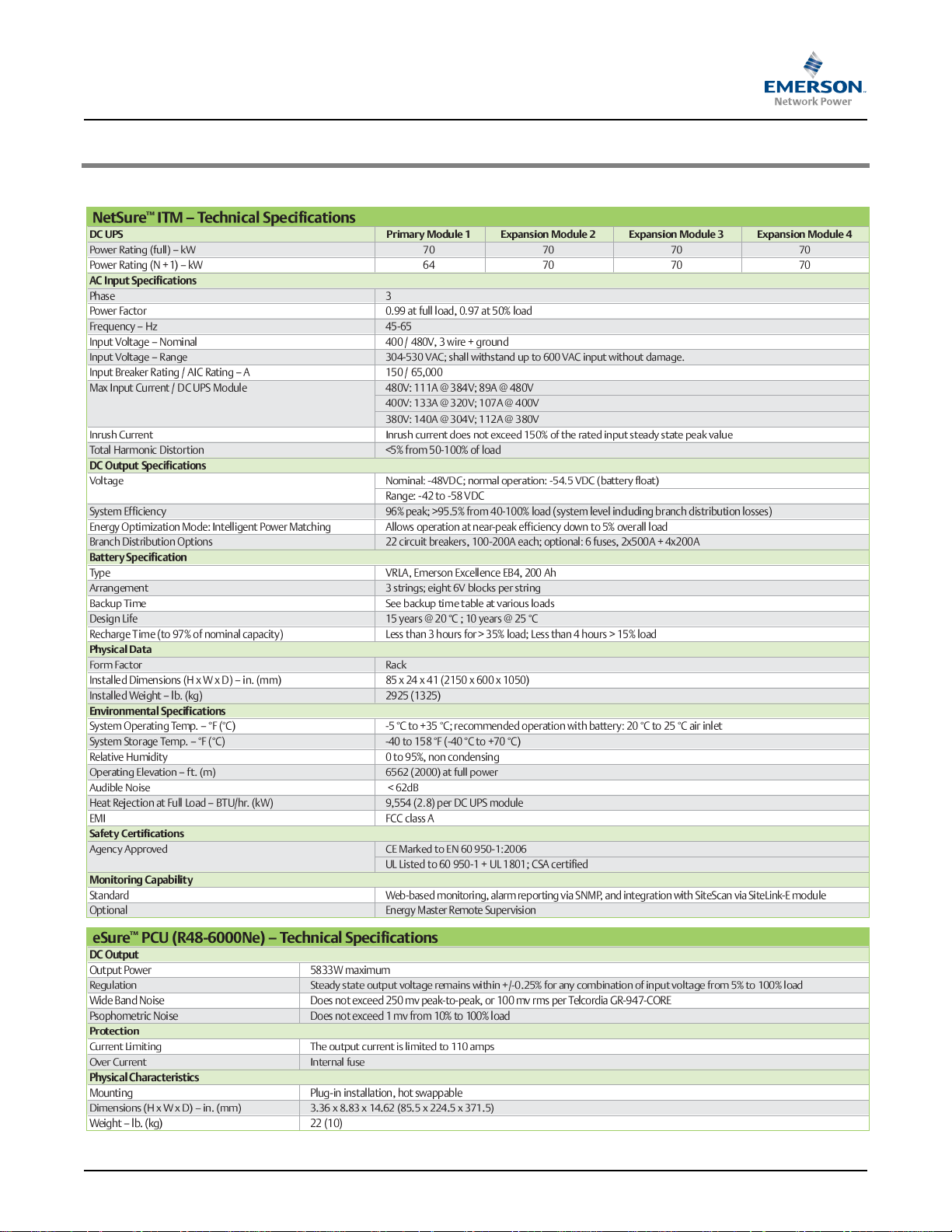
1 SITE PLANNING DATA
1.1 Technical Specifications
Spec. No: 582145500 Section 6037
Model: NetSure™ ITM Issue AC, April 8, 2013
Page 3
NetSure™ ITM with eSure™ Technology
3
Site Planning Data and System Drawings — 48V DC UPS
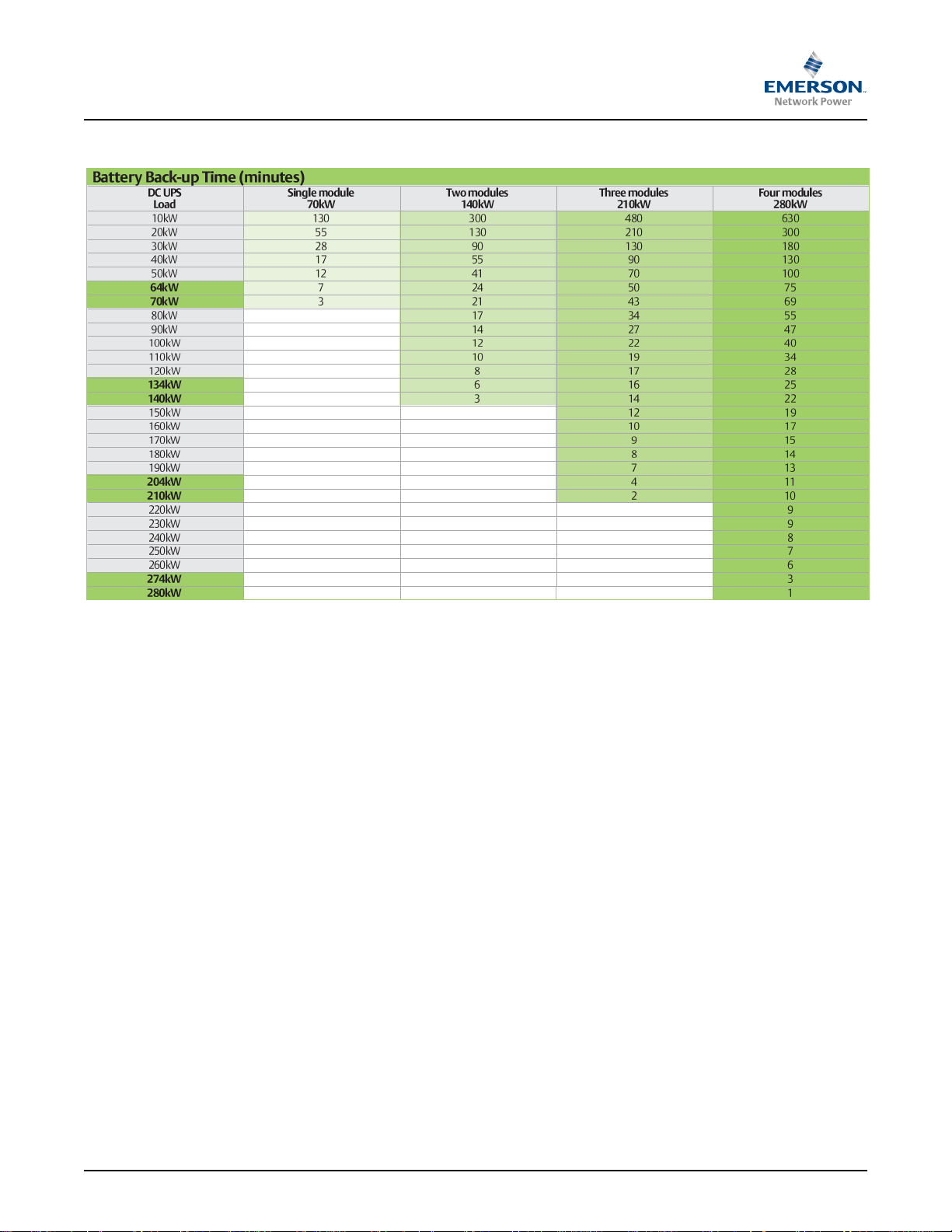
1.2 Battery Run Times
Spec. No: 582145500 Section 6037
Model: NetSure™ ITM Issue AC, April 8, 2013
Page 4
NetSure™ ITM with eSure™ Technology
4
Load
Shunts
Load
Shunts
Battery
Shunts
Battery
Fuse
Battery
LVD
PCU PCU PCU PCU PCU PCU
Controller and
Communication
Controller and
Communication
Load Breakers
or
Optional Fuses
Load Breakers
or
Optional Fuses
Battery
Shunts
Battery
Fuse
Battery
LVD
AC Input B
(Optional)
AC Input A
AC Input B
(Optional)
AC Input A
PCU
Breakers
(Note 4)
Current
Transformer
PCU
Breakers
(Note 4)
Current
Transformer
AC
Circuit
Breakers
(Note 3)
AC
Circuit
Breakers
(Note 3)
Internal
DC-link
PRIMARY
DC UPS
MODULE (1)
EXPANSION
DC UPS
MODULES (2-4)
Internal
COM-link
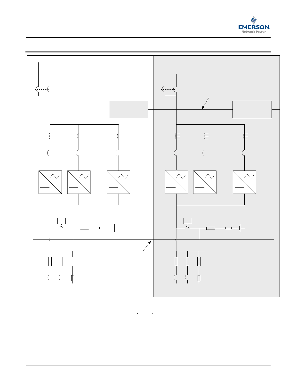
NOTES
1. DUAL AC INPUT VERSION OPTIONAL.
2. RECOMMENDED INPUT WIRE SIZE 2/0 AWG, 90 C (194 F), SEE NEC TABLE 310.16.
3. MAX INPUT CURRENT:
480V: 111A @ 384V; 89A @ 480V
400V: 133A @ 320V; 107A @ 400V
380V: 140A @ 304V; 112A @ 380V
3. SYSTEM AC INPUT BREAKER(S) RATED 150A, 65kAIC.
4. PCU AC INPUT BREAKERS RATED 32A, 5000AIC. TWO (2) PCUs PER BREAKER.
Site Planning Data and System Drawings — 48V DC UPS
2 ONE LINE DIAGRAM
Spec. No: 582145500 Section 6037
Model: NetSure™ ITM Issue AC, April 8, 2013
Page 5

NetSure™ ITM with eSure™ Technology
5
23.62
(600)
84.33
(2142)
top
cabled
84.72
(2152)
bottom
cabled
Battery Compartment
Conduits for
AC Inputs
41.34
(1050)
DC Power System
Compartment
Z
X
Y
Top Cabled Version
X = 11.81(300)
Y = 26.38 (670)
Z = 36.61 (930)
Bottom Cabled Version
X = 11.81(300)
Y = 26.38 (670)
Z = 40.55 (1030)
CENTER OF GRAVITY
26.38
(670)
CG
11.81
(300)
(Bottom
cabled)
CG
11.81
(300)
36.61
(930)
40.55
(1030)
CG
(top
cabled)
23.62
(600)
Battery Compartment
Conduits for
AC Inputs
41.34
(1050)
DC Power System
Compartment
26.38
(670)
CG
11.81
(300)
DC UPS MODULE WITH
TOP FEED DC DISTRIBUTION
DC UPS MODULE WITH
BOTTOM FEED DC DISTRIBUTION
Top View
Top View
Front View
Notes:
1. Dimensions are in inches (millimeters).
2. Weight (fully loaded):2925 lbs / 1325 kg.
3. Heat Rejection: 9554 BTU/h at full load (per module).
4. May be installed on concrete slab or raised floor.
System can be expanded eitherto
the left or the right of the Primary Module.
Single Module
70kW (full)
64kW (n+1)
TwoModules
140kW (full)
134kW (n+1)
Three Modules
210kW (full)
204kW (n+1)
Four Modules
280kW (full)
274kW (n+1)
Site Planning Data and System Drawings — 48V DC UPS
3 SYSTEM OUTLINE DRAWINGS
3.1 Mechanical Installation and Outline Drawings
3.1.1 Individual Cabinet Mechanical Data
3.1.2 System Configurations
Spec. No: 582145500 Section 6037
Model: NetSure™ ITM Issue AC, April 8, 2013
Page 6

NetSure™ ITM with eSure™ Technology
6
AC Input Conduit
* PCUs (12 x 5833W)
ACU+ (Controller)
Battery Fuses (800A)
(Battery leads factory
connected and routed to
Battery Compartment.)
SM-AC (AC Input Monitoring)
Battery Return and Load Return
(Battery return leads factory
connected and routed to
Battery Compartment.)
12
1 11
22
AC Input Circuit Breaker(s)
(150A, 65kAIC)
Internal Circuit Breakers (32A)
(Each Circuit Breaker Feeds Two PCUs)
LVD Contactor
PCU* Position
#1
#3
#5
#7
#9
#11
PCU* Position
#2
#4
#6
#8
#10
#12
Feeds PCU Position (left to right)
#1/#2, #3/#4, #5/#6, #7/#8, #9/#10, #11/#12
Front View
(door removed)
Load Distribution Devices
(DC distribution circuit breakers,
22 positions, 100-200A)
(Fuse Option Available)
Site Planning Data and System Drawings — 48V DC UPS
3.1.3 Main Components
3.1.3.1 Bottom Cabled Configuration - Circuit Breaker Load Distribution (Standard)
Spec. No: 582145500 Section 6037
Model: NetSure™ ITM Issue AC, April 8, 2013
Page 7

NetSure™ ITM with eSure™ Technology
7
AC Input
Conduit Openings
* PCUs (12 x 5833W)
ACU+ (Controller)
Battery Fuses (800A)
(Battery leads factory
connected and routed to
Battery Compartment.)
SM-AC (AC Input Monitoring)
Battery Return and Load Return
(Battery return leads factory
connected and routed to
Battery Compartment.)
12
1 11
22
AC Input Circuit Breaker(s)
(150A, 65kAIC)
Internal Circuit Breakers (32A)
(Each Circuit Breaker Feeds Two PCUs)
LVD Contactor
PCU* Position
#1
#3
#5
#7
#9
#11
PCU* Position
#2
#4
#6
#8
#10
#12
Feeds PCU Position (left to right)
#1/#2, #3/#4, #5/#6, #7/#8, #9/#10, #11/#12
Front View
(door removed)
Load Distribution Devices
(DC distribution circuit breakers,
22 positions, 100-200A)
(Fuse Option Available)
Site Planning Data and System Drawings — 48V DC UPS
3.1.3.2 Top Cabled Configuration - Circuit Breaker Load Distribution (Standard)
Spec. No: 582145500 Section 6037
Model: NetSure™ ITM Issue AC, April 8, 2013
Page 8

NetSure™ ITM with eSure™ Technology
8
Battery
Compartment
BFU
Distr.
Distr.
Raised Floor
Hot Aisle
Cold Aisle
A
Air Flow
Note 2
Side View
Support
Stand
½” (12mm) Floor
Anchoring Bolts
(4 places)
Top
Front
Notes:
1. Dimensions are in inches (millimeters).
2. Do not block air intake openings.
3. Minimum under floor space for underfloor
output cable runs: A= 1f (300mm).
4. Run cables not to block air openings for battery
cooling.
Battery
Compartment
Conduits for
AC Inputs
DC Power System
Compartment
35.43
(900)
17.72 (450)
8.86
(225)
9.84
(250)
19.68
(500)
9.84
(250)
8.86
(225)
Optional Floor
Opening for
Battery Cooling
PCUs
PCUs
PCUs
PCUs
PCUs
PCUs
P/N 547823
36” Tall Floor Stand
P/N 547822
24” Tall Floor Stand
Site Planning Data and System Drawings — 48V DC UPS
3.1.4 Bottom Cable Entry
Spec. No: 582145500 Section 6037
Model: NetSure™ ITM Issue AC, April 8, 2013
Page 9

NetSure™ ITM with eSure™ Technology
9
Note 2
Distr.
Distr.
Hot Aisle
Cold Aisle
Air Flow
Concrete
Floor (slab)
Side View
Notes:
1. Dimensionsare in inches (millimeters).
2. Do not block air intake openings.
Top
Battery
Compartment
DC Power
System
Compartment
Openings for
Output Cables
Front
Cable Tray Supports
if Mounted on Topof
Module
Front View
Cable Tray
Cable Run
Battery
Compartment
PCUs
PCUs
PCUs
PCUs
PCUs
PCUs
Top View
Battery
Compartment
Openings for
Output Cables
Cable Tray
23.62
(600)
BFU
½” (12mm) Floor
Anchoring Bolts
(4 places)
35.43
(900)
19.68
(500)
Air Exchange
(keep clear)
AC Input
Conduit Openings
Site Planning Data and System Drawings — 48V DC UPS
3.1.5 Top Cable Entry
Spec. No: 582145500 Section 6037
Model: NetSure™ ITM Issue AC, April 8, 2013
Page 10

NetSure™ ITM with eSure™ Technology
10
DETAIL E
2"
RECOMMENDEDCOUPLING:
RACOTYPE 2628
(GRAINGER 3LV08) OR
THOMASBETTSTYPE
TK126US
COMMUNICATIONLINKS BETWEENCABINETS:
1. RS-485BUS WIRES(TWISTEDYELLOW/WHITEWIRES) SHALL BE CONNECTEDTO SM-AC.
2. CAN-BUSWIRES (TWISTED BLACK/WHITEWIRES) SHALL BEINTERCONNECTED.
3. CONTACTORCONTROLCABLES SHALL BE INTERCONNECTED.
NOTE
1. WHENCONNECTINGOUTPUT DISTRIBUTION CABLES– START WHITH INNER ROWFIRST.
2. THE DCDISTRIBUTION GROUND/RETURNBUSBAR MUST BE CONNECTEDVIA A SOLID
SINGLE-POINT GROUNDING LEAD TOTHE MAINBUILDINGGROUND.REFER TONEC,
TABLE250-122FOR GROUNDINGCONDUCTOR SIZE.
DETAIL D
ENTESC
USB
RJ45
USB
INPUTAC CONDUIT(S)
SEE DETAIL ”E”
CONTROLLER
SEEDETAIL ”D”
INPUTAC CONNECTION
SEEDETAIL ”A”
INPUTAC CABLE
ROUTING
CABINET GROUNDING
SUITABLE CABLE LUGS
WITH HOLEDIA 3/8" (M10)
TYPICAL LUGTHOMAS
& BETTS TYPE 54136
RECOMMENDED TORQUE
407-434in-lbs (46-49 Nm).
SIDEPLATES ARE ONLY
DELIVEREDON MAIN
CABINET. SHALL BE
MOVEDTO THELAST
EXTENSIONCABINET IN
A ROW
1"
SUITABLE CABLE LUGSWITH HOLE DIA3/8" (M10)
TYPICAL LUGTHOMAS& BETTSTYPE 54209
RECOMMENDED TORQUE 407-434 in-lbs (46-49Nm)
DETAIL C (Circuit Breaker Option)
1”
SUITABLE CABLELUGS WITH HOLEDIA 3/8"(M10)
TYPICALLUG THOMAS &BETTS TYPE 54109
RECOMMENDED TORQUE407-434 in-lbs (46-49Nm)
DETAIL B (Circuit Breaker Option)
1 .7 5 "
1.5”
DETAIL C (Fuse Option)
S U IT A BLE C A B LE L U GS WITH H O L E D IA 1 /2 " ( M1 2 )
TY PIC AL LU G T H O MA S & B E T TS T Y P E 54 28 2 (35 0 kc m il )
R E C OMM E N D E D TOR Q U E 690-743 in-lbs (78-84 Nm)
1 .7 5 "1. 7 5 "
DETAIL B (Fuse Option)
S U IT A BLE C A B LE L U GS WITH H O L E D IA 1 /2 " ( M1 2 )
TY PIC AL LU G T H O MA S & B E T TS T Y P E 54 28 2 (35 0 kc m il )
R E C OMM E N D E D TOR Q U E 690-743 in-lbs (78-84 Nm)
NEGATIVE BUSBAR
SEEDETAIL ”C”
(LOAD)
POSITIVE BUSBAR
SEE DETAIL ”B”
(RETURN)
INPUTGROUNDING
CONNECTION
LUGS5/16" (M8)
TYPICAL LUG THOMAS&
BETTSTYPE 54109
RECOMMENDED TORQUE
204-221 in-lbs (23-25 Nm)
DETAIL A
ONEOR TWO AC CIRCUITBREAKERS,
NO LUGS NEEDED.
MARKCABLESA-L1, A-L2AND A-L3(B-L1, B-L2,B-L3)
RECOMMENDED TORQUE 124in-lbs (14Nm)
factory wiring
L1 L2 L3
AC IN A
L1 L2 L3
AC IN B
GND
Stud
GND
Stud
Site Planning Data and System Drawings — 48V DC UPS
4 CONNECTON DETAILS
4.1 Bottom Cable Entry Electrical Connection Detail
Spec. No: 582145500 Section 6037
Model: NetSure™ ITM Issue AC, April 8, 2013
Page 11

NetSure™ ITM with eSure™ Technology
11
KNOCKOUTSFOR INPUT
AC CONDUIT(S) SIZE2"
OR COUPLING(S) SIZE2"
(NOT INCLUDED)
CONTROLLER
SEE DETAIL ”D”
INPUTAC CONNECTION
SEE DETAIL ”A”
DETAIL E
2"
RECOMMENDEDCOUPLING:
RACO TYPE 2628
(GRAINGER 3LV08) OR
THOMASBETTS TYPE
TK126US
INPUTAC CABLE
ROUTING
CABINETGROUNDING
SUITABLECABLE LUGS
WITH HOLE DIA3/8" (M10)
TYPICALLUG THOMAS
& BETTSTYPE 54136
RECOMMENDEDTORQUE
407-434in-lbs (46-49Nm).
SIDE PLATES ARE ONLY
DELIVERED ONMAIN
CABINET. SHALLBE
MOVEDTO THE LAST
EXTENSION CABINETIN
A ROW.
DETAIL B (Circuit Breaker Option)
1”
SUITABLECABLE LUGS WITH HOLE DIA3/8" (M10)
TYPICALLUG THOMAS & BETTS TYPE 54109
RECOMMENDEDTORQUE407-434 in-lbs(46-49 Nm)
DETAIL C (Circuit Breaker Option)
1"
SUITABLECABLE LUGS WITH HOLE DIA 3/8"(M10)
TYPICALLUG THOMAS& BETTSTYPE 54209
RECOMMENDEDTORQUE 407-434in-lbs (46-49Nm)
COMMUNICATIONLINKS BETWEEN CABINETS:
1. RS-485 BUS WIRES (TWISTED YELLOW/WHITEWIRES) SHALL BE CONNECTEDTO SM-AC.
2. CAN-BUSWIRES (TWISTEDBLACK/WHITEWIRES) SHALL BEINTERCONNECTED.
3. CONTACTOR CONTROLCABLES SHALL BE INTERCONNECTED.
NOTE
1. WHEN CONNECTING OUTPUT DISTRIBUTION CABLES – START WITHINNER ROWFIRST.
2. THEDC DISTRIBUTIONGROUND/RETURNBUSBAR MUST BECONNECTEDVIA A SOLID
SINGLE-POINTGROUNDING LEADTO THEMAIN BUILDINGGROUND.REFER TONEC,
TABLE250-122 FOR GROUNDING CONDUCTOR SIZE.
DETAIL D
ENTESC
USB
RJ45
USB
DETAIL A
ONE OR TWO AC CIRCUIT BREAKERS,
NO LUGS NEEDED.
MARKCABLES A-L1,A-L2 ANDA-L3 (B-L1, B-L2, B-L3)
RECOMMENDEDTORQUE124 in-lbs (14Nm)
DETAIL B (Fuse Option)
1 . 75 "1 . 75 "
S U IT AB LE C A B L E LU GS W ITH HOLE D IA 1/2 " (M 1 2)
TYPICA L L U G T H OM A S & BETT S T Y P E 54 2 82 (3 50k cmi l)
R E C OMME N D ED T ORQUE 690-743 in-lbs (78-84 Nm)
DETAIL C (Fuse Option)
1 . 75 "
1.5”
S U IT AB LE C A B L E LU GS W ITH HOLE D IA 1/2 " (M 1 2)
TYPICA L L U G T H OM A S & BETT S T Y P E 54 2 82 (3 50k cmi l)
R E C OMME N D ED T ORQUE 690-743 in-lbs (78-84 Nm)
NEGATIVE BUSBAR
SEE DETAIL ”C”
(LOAD)
POSITIVEBUSBAR
SEE DETAIL ”B”
(RETURN)
INPUTGROUNDING
CONNECTION
LUGS5/16" (M8)
TYPICAL LUGTHOMAS &
BETTSTYPE 54109
RECOMMENDED TORQUE
204-221in-lbs (23-25Nm)
factory wiring
AC IN A
L1 L2 L3
AC IN B
L1 L2 L3
GND
Stud
GND
Stud
Site Planning Data and System Drawings — 48V DC UPS
4.2 Top Cable Entry Electrical Connection Detail
Spec. No: 582145500 Section 6037
Model: NetSure™ ITM Issue AC, April 8, 2013
Page 12

NetSure™ ITM with eSure™ Technology
Site Planning Data and System Drawings — 48V DC UPS
Spec. No: 582145500 Section 6037
Model: NetSure™ ITM Issue AC, April 8, 2013
 Loading...