

Page 1
Liebert® IntelliSlot® Modbus 485, Modbus IP and BACnet IP
Reference Guide
Page 2

Page 3

TABLE OF CONTENTS
1.0 LIEBERT EQUIPMENT COMPATIBILITY . . . . . . . . . . . . . . . . . . . . . . . . . . . . . . . . . . . . . . . . .1
1.1 What’s New in This Manual . . . . . . . . . . . . . . . . . . . . . . . . . . . . . . . . . . . . . . . . . . . . . . . . . . . 1
1.2 Connectivity to Liebert IntelliSlot Using Modbus 485, Modbus IP or BACnet IP . . . . . . . . . 1
1.2.1 How to Use This Manual . . . . . . . . . . . . . . . . . . . . . . . . . . . . . . . . . . . . . . . . . . . . . . . . . . . . 1
1.3 Compatibility with Liebert Equipment. . . . . . . . . . . . . . . . . . . . . . . . . . . . . . . . . . . . . . . . . . . 2
Table 1 Liebert Equipment and Compatible Liebert IntelliSlot® Cards . . . . . . . . . . . . . . . . . . . . . 2
2.0 MODBUS COMMUNICATIONS . . . . . . . . . . . . . . . . . . . . . . . . . . . . . . . . . . . . . . . . . . . . . . . . 5
2.1 Implementation Basics. . . . . . . . . . . . . . . . . . . . . . . . . . . . . . . . . . . . . . . . . . . . . . . . . . . . . . . . 5
2.2 Transmission Format . . . . . . . . . . . . . . . . . . . . . . . . . . . . . . . . . . . . . . . . . . . . . . . . . . . . . . . . . 5
Table 2 Modbus Remote Transmission Unit settings for Liebert IntelliSlot 485/IP interface
card . . . . . . . . . . . . . . . . . . . . . . . . . . . . . . . . . . . . . . . . . . . . . . . . . . . . . . . . . . . . . . . . . . . . . 5
2.3 Modbus Packet Format . . . . . . . . . . . . . . . . . . . . . . . . . . . . . . . . . . . . . . . . . . . . . . . . . . . . . . . 5
2.3.1 Device Address . . . . . . . . . . . . . . . . . . . . . . . . . . . . . . . . . . . . . . . . . . . . . . . . . . . . . . . . . . . . 5
2.3.2 Function Code . . . . . . . . . . . . . . . . . . . . . . . . . . . . . . . . . . . . . . . . . . . . . . . . . . . . . . . . . . . . 6
Table 3 Supported Modbus function codes. . . . . . . . . . . . . . . . . . . . . . . . . . . . . . . . . . . . . . . . . . . . . 6
2.3.3 Data Fields . . . . . . . . . . . . . . . . . . . . . . . . . . . . . . . . . . . . . . . . . . . . . . . . . . . . . . . . . . . . . . . 6
2.3.4 Error Check Field. . . . . . . . . . . . . . . . . . . . . . . . . . . . . . . . . . . . . . . . . . . . . . . . . . . . . . . . . . 6
2.4 RTU Framing . . . . . . . . . . . . . . . . . . . . . . . . . . . . . . . . . . . . . . . . . . . . . . . . . . . . . . . . . . . . . . . 6
Table 4 Query sample . . . . . . . . . . . . . . . . . . . . . . . . . . . . . . . . . . . . . . . . . . . . . . . . . . . . . . . . . . . . . 6
Table 5 Response sample . . . . . . . . . . . . . . . . . . . . . . . . . . . . . . . . . . . . . . . . . . . . . . . . . . . . . . . . . . 6
3.0 MODBUS 485 AND MODBUS IP PROTOCOLS . . . . . . . . . . . . . . . . . . . . . . . . . . . . . . . . . . . .7
3.1 Thermal Management Products . . . . . . . . . . . . . . . . . . . . . . . . . . . . . . . . . . . . . . . . . . . . . . . . 7
Table 6 Liebert Challenger 3000™, Liebert Challenger ITR™, Liebert CW™, Liebert Deluxe
System/3
and Coil. . . . . . . . . . . . . . . . . . . . . . . . . . . . . . . . . . . . . . . . . . . . . . . . . . . . . . . . . . . . . . . . . . 7
Table 7 Extra notes key to Table 6 . . . . . . . . . . . . . . . . . . . . . . . . . . . . . . . . . . . . . . . . . . . . . . . . . 12
Table 8 Liebert Challenger 3000
System/3
and Holding . . . . . . . . . . . . . . . . . . . . . . . . . . . . . . . . . . . . . . . . . . . . . . . . . . . . . . . . . . . . . 13
Table 9 Extra notes key to Table 8 . . . . . . . . . . . . . . . . . . . . . . . . . . . . . . . . . . . . . . . . . . . . . . . . . 25
Table 10 Liebert Challenger 3000
System/3
Table 11 Liebert CRV
Table 12 Liebert CRV
Table 13 Liebert CRV
Table 14 Liebert HPC
Table 15 Liebert HPC
™
, Liebert DS™, Liebert DSE™, Liebert HPM™, Liebert PeX™ - Status
™
™
, Liebert DS™, Liebert DSE™, Liebert HPM™, Liebert PeX™ - Input
™
, Liebert DS™, Liebert DSE™, Liebert HPM™, Liebert PeX™ - Glossary . . . . . 26
™
- Status and Coil . . . . . . . . . . . . . . . . . . . . . . . . . . . . . . . . . . . . . . . . . . . . . 39
™
- Input and Holding . . . . . . . . . . . . . . . . . . . . . . . . . . . . . . . . . . . . . . . . . . . 41
™
- Glossary . . . . . . . . . . . . . . . . . . . . . . . . . . . . . . . . . . . . . . . . . . . . . . . . . . . 45
™
(Chiller) - Status and Coil . . . . . . . . . . . . . . . . . . . . . . . . . . . . . . . . . . . . . . 49
™
(Chiller) - Input and Holding . . . . . . . . . . . . . . . . . . . . . . . . . . . . . . . . . . . 51
, Liebert Challenger ITR™, Liebert CW™, Liebert Deluxe
™
, Liebert Challenger ITR™, Liebert CW™, Liebert Deluxe
Table 16 Extra notes key to Table 15 . . . . . . . . . . . . . . . . . . . . . . . . . . . . . . . . . . . . . . . . . . . . . . . . 55
Table 17 Liebert HPC
™
(Chiller) - Glossary . . . . . . . . . . . . . . . . . . . . . . . . . . . . . . . . . . . . . . . . . . . 55
i
Page 4

Table 18 Liebert XDC™ - Status and Coil . . . . . . . . . . . . . . . . . . . . . . . . . . . . . . . . . . . . . . . . . . . . . 58
Table 19 Liebert XDC
Table 20 Liebert XDP
Table 21 Liebert XDP
Table 22 Liebert XDP
Table 23 Liebert DS
Table 24 Liebert DS
Table 25 Liebert XDF
Table 26 Liebert XDF
Table 27 Liebert Challenger 3000
™
ICS
- Input and Holding - LAM. . . . . . . . . . . . . . . . . . . . . . . . . . . . . . . . . . . . . . . . . . . . . 83
Table 28 Liebert DataMate
™
- Input and Holding . . . . . . . . . . . . . . . . . . . . . . . . . . . . . . . . . . . . . . . . . . . 59
™
- Status and Coil . . . . . . . . . . . . . . . . . . . . . . . . . . . . . . . . . . . . . . . . . . . . . 60
™
- Input and Holding . . . . . . . . . . . . . . . . . . . . . . . . . . . . . . . . . . . . . . . . . . . 62
™
- Glossary . . . . . . . . . . . . . . . . . . . . . . . . . . . . . . . . . . . . . . . . . . . . . . . . . . . 72
™
and Liebert PeX™ - Status and Coil. . . . . . . . . . . . . . . . . . . . . . . . . . . . . . . . 75
™
and Liebert PeX™ - Input and Holding . . . . . . . . . . . . . . . . . . . . . . . . . . . . . 78
™
- Status and Coil . . . . . . . . . . . . . . . . . . . . . . . . . . . . . . . . . . . . . . . . . . . . . 81
™
- Input and Holding . . . . . . . . . . . . . . . . . . . . . . . . . . . . . . . . . . . . . . . . . . . 82
™
, Liebert Deluxe System/3™, Liebert Himod™, Liebert
™
, Liebert Mini-Mate Plus™, Liebert Mini-Mate2™ - Input and
Holding - L0B . . . . . . . . . . . . . . . . . . . . . . . . . . . . . . . . . . . . . . . . . . . . . . . . . . . . . . . . . . . . 85
Table 29 Liebert DataMate
Table 30 Liebert Mini-Mate2
Table 31 Liebert Atlas Air
™
, Liebert Mini-Mate2™ - Input and Holding - MM2 . . . . . . . . . . . . . . 86
™
8 Ton - Input and Holding - L8T . . . . . . . . . . . . . . . . . . . . . . . . . . . 88
™
, Liebert Atlas PEC™, Liebert LECS 15™ - Input and
Holding - C10 2-step . . . . . . . . . . . . . . . . . . . . . . . . . . . . . . . . . . . . . . . . . . . . . . . . . . . . . . 90
Table 32 Liebert Atlas Air
™
, Liebert Atlas PEC™, Liebert CEMS 100™ - Input and
Holding - C100 4-step . . . . . . . . . . . . . . . . . . . . . . . . . . . . . . . . . . . . . . . . . . . . . . . . . . . . . 92
3.2 Power Distribution and Power Conditioning Products . . . . . . . . . . . . . . . . . . . . . . . . . . . . . 94
Table 33 Liebert Datawave™, Liebert FPC™, Liebert PPC™ - Input and Holding - PMP, PM2
Options for Liebert FPC and Liebert PPC . . . . . . . . . . . . . . . . . . . . . . . . . . . . . . . . . . . . . 94
Table 34 Liebert Datawave
™
, Liebert FPC™, Liebert PPC™ - Input and Holding - PMP
Option for Liebert FPC and Liebert PPC . . . . . . . . . . . . . . . . . . . . . . . . . . . . . . . . . . . . . . 96
Table 35 Liebert FDC
Table 36 Liebert FDC
Table 37 Liebert FDC
Table 38 Liebert STS
Table 39 Liebert STS2
™
, Liebert FPC™, Liebert RDC™, Liebert RX™ - Status and Coil . . . . . . . . . 97
™
, Liebert FPC™, Liebert RDC™, Liebert RX™ - Input and Holding. . . . . . 100
™
, Liebert FPC™, Liebert RDC™, Liebert RX™ - Glossary. . . . . . . . . . . . . . 109
™
, Liebert STS/PDU™ - Input and Holding - STS. . . . . . . . . . . . . . . . . . . . . 112
™
, Liebert STS2/PDU™ - Input and Holding - STS2. . . . . . . . . . . . . . . . . . 114
3.3 UPS Systems. . . . . . . . . . . . . . . . . . . . . . . . . . . . . . . . . . . . . . . . . . . . . . . . . . . . . . . . . . . . . . 118
Table 40 Liebert APM™, Liebert NXC™, Liebert NXR™- Status and Coil . . . . . . . . . . . . . . . . . . . 118
Table 41 Liebert APM
Table 42 Liebert APM
Table 43 Liebert APS
Table 44 Liebert APS
Table 45 Liebert APS
Table 46 Liebert GXT2
Table 47 Liebert GXT2
Table 48 Liebert HiNet
™
, Liebert NXC™, Liebert NXR™- Input and Holding. . . . . . . . . . . . . . . . . 120
™
, Liebert NXC™, Liebert NXR™ - Glossary . . . . . . . . . . . . . . . . . . . . . . . . 122
™
- Status and Coil . . . . . . . . . . . . . . . . . . . . . . . . . . . . . . . . . . . . . . . . . . . . . 124
™
- Input and Holding . . . . . . . . . . . . . . . . . . . . . . . . . . . . . . . . . . . . . . . . . . 126
™
- Glossary . . . . . . . . . . . . . . . . . . . . . . . . . . . . . . . . . . . . . . . . . . . . . . . . . . 132
™
and Liebert GXT3™ - Status and Coil . . . . . . . . . . . . . . . . . . . . . . . . . . . 136
™
and Liebert GXT3™ - Input and Holding . . . . . . . . . . . . . . . . . . . . . . . . 137
™
- Status and Coil . . . . . . . . . . . . . . . . . . . . . . . . . . . . . . . . . . . . . . . . . . . 138
Table 49 Liebert HiNet - Input and Holding . . . . . . . . . . . . . . . . . . . . . . . . . . . . . . . . . . . . . . . . . . 138
Table 50 Liebert Nfinity
®
- Status and Coil . . . . . . . . . . . . . . . . . . . . . . . . . . . . . . . . . . . . . . . . . . . 139
ii
Page 5

Table 51 Liebert Nfinity® - Input and Holding . . . . . . . . . . . . . . . . . . . . . . . . . . . . . . . . . . . . . . . . 140
Table 52 Liebert NX
Table 53 Liebert NX
Table 54 Liebert NX 225-600kVA UPS - Input and Holding
Table 55 Liebert NXL
Table 56 Liebert NXL
Table 57 Liebert NXL
Table 58 Liebert NXL
™
- Status and Coil. . . . . . . . . . . . . . . . . . . . . . . . . . . . . . . . . . . . . . . . . . . . . . 141
™
- Input and Holding . . . . . . . . . . . . . . . . . . . . . . . . . . . . . . . . . . . . . . . . . . . 143
3
. . . . . . . . . . . . . . . . . . . . . . . . . . . . 145
™
- 60Hz, UL version (Model 40) - Status and Coil . . . . . . . . . . . . . . . . . . . 148
™
- 60Hz, UL version (Model 40) - Input and Holding . . . . . . . . . . . . . . . . 151
™
- 60Hz, UL version (Model 40) - Glossary. . . . . . . . . . . . . . . . . . . . . . . . . 163
™
- 50Hz, CE version (Models 48 and 49) - Status and Coil . . . . . . . . . . . . 168
Table 59 Liebert NXL™ - 50Hz, CE version (Models 48 and 49) - Input and Holding . . . . . . . . . 171
Table 60 Liebert NXL
Table 61 Liebert PowerSure
Table 62 Liebert PowerSure
Table 63 Liebert PowerSure
Table 64 Liebert PowerSure
Table 65 Liebert Series 300
Table 66 Liebert Series 300
Table 67 Liebert Series 600
Table 68 Liebert Series 600
Table 69 Liebert Series 610
™
- 50Hz, CE version (Models 48 and 49) - Glossary . . . . . . . . . . . . . . . . . 182
™
Interactive (before July 2008) - Status and Coil . . . . . . . . . . . . . . 190
™
Interactive (before July 2008) - Input and Holding. . . . . . . . . . . . 191
™
Interactive 2 - Status and Coil . . . . . . . . . . . . . . . . . . . . . . . . . . . . 192
™
Interactive 2 - Input and Holding. . . . . . . . . . . . . . . . . . . . . . . . . . 193
™
UPS - Status and Coil . . . . . . . . . . . . . . . . . . . . . . . . . . . . . . . . . . . 194
™
UPS - Input and Holding . . . . . . . . . . . . . . . . . . . . . . . . . . . . . . . . . 195
™
UPS - Status and Coil . . . . . . . . . . . . . . . . . . . . . . . . . . . . . . . . . . . 197
™
UPS - Input and Holding . . . . . . . . . . . . . . . . . . . . . . . . . . . . . . . . . 198
™
SCC UPS - Status and Coil . . . . . . . . . . . . . . . . . . . . . . . . . . . . . . . 199
Table 70 Liebert Series 610 SCC UPS - Input and Holding . . . . . . . . . . . . . . . . . . . . . . . . . . . . . . 200
Table 71 Liebert HiPulse
Table 72 Liebert SICE 7200
Table 73 Liebert Npower
™,
Liebert SICE 7200™- Input and Holding - SMM/SSM. . . . . . . . . . . . 201
™
- Input and Holding - SSC . . . . . . . . . . . . . . . . . . . . . . . . . . . . . . . . 203
™
- Input and Holding - IMP . . . . . . . . . . . . . . . . . . . . . . . . . . . . . . . . . . 205
3.4 Battery Monitoring Products . . . . . . . . . . . . . . . . . . . . . . . . . . . . . . . . . . . . . . . . . . . . . . . . . 207
Table 74 Alber® BDSU™ - Status and Coil . . . . . . . . . . . . . . . . . . . . . . . . . . . . . . . . . . . . . . . . . . . . 207
Table 75 Alber
®
BDSU™ - Input and Holding . . . . . . . . . . . . . . . . . . . . . . . . . . . . . . . . . . . . . . . . . 209
4.0 BACNET COMMUNICATIONS . . . . . . . . . . . . . . . . . . . . . . . . . . . . . . . . . . . . . . . . . . . . . .214
4.1 BACnet Protocol Implementation Conformance Statement . . . . . . . . . . . . . . . . . . . . . . . . 214
4.1.1 Segmentation Capability . . . . . . . . . . . . . . . . . . . . . . . . . . . . . . . . . . . . . . . . . . . . . . . . . . 214
4.1.2 Supported Services. . . . . . . . . . . . . . . . . . . . . . . . . . . . . . . . . . . . . . . . . . . . . . . . . . . . . . . 215
4.1.3 Standard Object Types Supported . . . . . . . . . . . . . . . . . . . . . . . . . . . . . . . . . . . . . . . . . . 216
4.1.4 Object Properties . . . . . . . . . . . . . . . . . . . . . . . . . . . . . . . . . . . . . . . . . . . . . . . . . . . . . . . . 217
4.2 Thermal Management Products . . . . . . . . . . . . . . . . . . . . . . . . . . . . . . . . . . . . . . . . . . . . . . 220
Table 76 Liebert Challenger 3000™, Liebert Challenger ITR™, Liebert CW™, Liebert Deluxe
System/3
Data . . . . . . . . . . . . . . . . . . . . . . . . . . . . . . . . . . . . . . . . . . . . . . . . . . . . . . . . . . . . . . . . . . 220
Table 77 Extra Notes to Table 76 . . . . . . . . . . . . . . . . . . . . . . . . . . . . . . . . . . . . . . . . . . . . . . . . . . 226
Table 78 Liebert Challenger 3000
System/3
Data . . . . . . . . . . . . . . . . . . . . . . . . . . . . . . . . . . . . . . . . . . . . . . . . . . . . . . . . . . . . . . . . . . 227
™
, Liebert DS™, Liebert DSE™, Liebert HPM™, Liebert PeX™ - Binary
™
™
, Liebert DS™, Liebert DSE™, Liebert HPM™, Liebert PeX™ - Analog
, Liebert Challenger ITR™, Liebert CW™, Liebert Deluxe
iii
Page 6

Table 79 Extra Notes to Table 78 . . . . . . . . . . . . . . . . . . . . . . . . . . . . . . . . . . . . . . . . . . . . . . . . . . 235
Table 80 Liebert Challenger 3000
System/3
™
, Liebert DS™, Liebert DSE™, Liebert HPM™, Liebert PeX™ - Multistate
™
, Liebert Challenger ITR™, Liebert CW™, Liebert Deluxe
Data . . . . . . . . . . . . . . . . . . . . . . . . . . . . . . . . . . . . . . . . . . . . . . . . . . . . . . . . . . . . . . . . . . 236
Table 81 Extra Notes to Table 80 . . . . . . . . . . . . . . . . . . . . . . . . . . . . . . . . . . . . . . . . . . . . . . . . . . 243
Table 82 Liebert Challenger 3000
System/3
PeX
Table 83 Liebert CRV
Table 84 Liebert CRV
Table 85 Liebert CRV
Table 86 Liebert CRV
Table 87 Liebert HPC
Table 88 Liebert HPC
Table 89 Liebert HPC
™
™
, Liebert DS™, Liebert DSE™, Liebert HPM™, Liebert
- Glossary . . . . . . . . . . . . . . . . . . . . . . . . . . . . . . . . . . . . . . . . . . . . . . . . . . . . . . . . . 244
™
- Binary Data . . . . . . . . . . . . . . . . . . . . . . . . . . . . . . . . . . . . . . . . . . . . . . . 256
™
- Analog Data . . . . . . . . . . . . . . . . . . . . . . . . . . . . . . . . . . . . . . . . . . . . . . . 259
™
- Multistate Data . . . . . . . . . . . . . . . . . . . . . . . . . . . . . . . . . . . . . . . . . . . . 262
™
- Glossary . . . . . . . . . . . . . . . . . . . . . . . . . . . . . . . . . . . . . . . . . . . . . . . . . . 265
™
- Binary Data . . . . . . . . . . . . . . . . . . . . . . . . . . . . . . . . . . . . . . . . . . . . . . . 271
™
- Analog Data . . . . . . . . . . . . . . . . . . . . . . . . . . . . . . . . . . . . . . . . . . . . . . . 273
™
- Multistate Data . . . . . . . . . . . . . . . . . . . . . . . . . . . . . . . . . . . . . . . . . . . . 275
™
, Liebert Challenger ITR™, Liebert CW™, Liebert Deluxe
Table 90 Extra Notes. . . . . . . . . . . . . . . . . . . . . . . . . . . . . . . . . . . . . . . . . . . . . . . . . . . . . . . . . . . . . 276
Table 91 Liebert HPC
Table 92 Liebert XDP
Table 93 Liebert XDP
Table 94 Liebert XDP
Table 95 Liebert XDP
Table 96 Liebert DataMate
Table 97 Liebert Mini-Mate2
™
- Glossary . . . . . . . . . . . . . . . . . . . . . . . . . . . . . . . . . . . . . . . . . . . . . . . . . . 276
™
, Liebert XDC™ - Binary Data . . . . . . . . . . . . . . . . . . . . . . . . . . . . . . . . . . 279
™
, Liebert XDC™ - Analog Data . . . . . . . . . . . . . . . . . . . . . . . . . . . . . . . . . . 281
™
, Liebert XDC™ - Multistate Data . . . . . . . . . . . . . . . . . . . . . . . . . . . . . . . 283
™
, Liebert XDC™ - Glossary . . . . . . . . . . . . . . . . . . . . . . . . . . . . . . . . . . . . . 290
™
, Liebert Mini-Mate2™ - MM2 . . . . . . . . . . . . . . . . . . . . . . . . . . . . . . 297
™
8 Ton - L8T . . . . . . . . . . . . . . . . . . . . . . . . . . . . . . . . . . . . . . . . . . . 298
4.3 UPS Systems. . . . . . . . . . . . . . . . . . . . . . . . . . . . . . . . . . . . . . . . . . . . . . . . . . . . . . . . . . . . . . 299
Table 98 Liebert APM™, Liebert NXC™, Liebert NXR™ - Binary Data . . . . . . . . . . . . . . . . . . . . . 299
Table 99 Liebert APM
Table 100 Liebert APM
Table 101 Liebert APM
Table 102 Liebert APS
Table 103 Liebert APS
Table 104 Liebert APS
Table 105 Liebert APS
Table 106 Liebert NXL
Table 107 Liebert NXL
Table 108 Liebert NXL
Table 109 Liebert NXL
Table 110 Liebert NXL
Table 111 Liebert NXL
Table 112 Liebert NXL
Table 113 Liebert NXL
™
, Liebert NXC™, Liebert NXR™ - Analog Data . . . . . . . . . . . . . . . . . . . . . 301
™
, Liebert NXC™, Liebert NXR™ - Multistate Data . . . . . . . . . . . . . . . . . . 302
™
, Liebert NXC™, Liebert NXR™ - Glossary . . . . . . . . . . . . . . . . . . . . . . . . 303
™
- Binary Data . . . . . . . . . . . . . . . . . . . . . . . . . . . . . . . . . . . . . . . . . . . . . . . 306
™
- Analog Data . . . . . . . . . . . . . . . . . . . . . . . . . . . . . . . . . . . . . . . . . . . . . . . 308
™
- Multistate Data . . . . . . . . . . . . . . . . . . . . . . . . . . . . . . . . . . . . . . . . . . . . 310
™
- Glossary . . . . . . . . . . . . . . . . . . . . . . . . . . . . . . . . . . . . . . . . . . . . . . . . . . 312
™
- 60Hz, UL version (Model 40) - Binary Data . . . . . . . . . . . . . . . . . . . . . . 316
™
- 60Hz, UL version (Model 40) - Analog Data . . . . . . . . . . . . . . . . . . . . . 321
™
- 60Hz, UL version (Model 40) - Multistate Data. . . . . . . . . . . . . . . . . . . 327
™
- 60Hz, UL version (Model 40) - Glossary. . . . . . . . . . . . . . . . . . . . . . . . . 333
™
- 50 Hz, CE version (Models 48 and 49)—Binary Data . . . . . . . . . . . . . . 341
™
- 50 Hz, CE version (Models 48 and 49)—Analog Data. . . . . . . . . . . . . . 345
™
- 50 Hz, CE version (Models 48 and 49)—Multistate Data . . . . . . . . . . . 348
™
- 50 Hz, CE version (Models 48 and 49)—Glossary . . . . . . . . . . . . . . . . . 355
iv
Page 7

Liebert Equipment Compatibility - What’s New in This Manual
1.0 LIEBERT EQUIPMENT COMPATIBILITY
1.1 What’s New in This Manual
Emerson Network Power® has introduced a new Liebert IntelliSlot® card platform—the Liebert
IntelliSlot Unity
of existing cards into a common, unified platform. Liebert IS-UNITY
available third-party protocols and the Liebert IS-UNITY-DP
™
card. This platform combines the Modbus 485, Modbus IP and BACnet IP outputs
™
™
allows selecting one of the
allows selection of two of the available
protocols.
The Liebert IS-UNITY and LiebertIS-UNITY-DP cards are interchangeable with the IS-485L,
IS-485X, IS-IPBML, IS-IPBMX, IS-WEBL and IS-WEBX cards for the protocols offered. The
information output by the Unity cards is the same as the output of the IS-485L, IS-485X, IS-IPBML
and IS-IPBMX cards. The cards offer Modbus IP/485 and BACnet IP.
The Liebert NX
™
225-600kVA UPS is also supported with the Chloride ManageUPS Net Adapter +B
communication card so the Modbus mapping supported with this configuration has been included.
1.2 Connectivity to Liebert IntelliSlot Using Modbus 485, Modbus IP or BACnet IP
This publication describes the Modbus and BACnet communications protocols available for
communication with Emerson Network Power equipment. Included are the Liebert IntelliSlot
Modbus 485, Modbus IP and the BACnet IP communications cards.
• The Modbus information includes implementation basics, supported types, frame format, function
code support and similar subjects.
• The BACnet information includes the BACnet service listing, object types, device objects, analog
objects, binary objects, multistate objects and BACnet engineering units.
1.2.1 How to Use This Manual
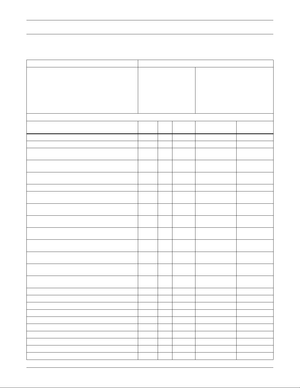
Table 1 shows the type of Liebert IntelliSlot card required for selected Liebert products. Find the
product first and the Reference Table, the three columns to the right of that are the cards supported
for the product.
The information is organized by Product Name, Table Number, Controller Protocol and Card Part
Number.
Modbus tables are first and BACnet tables second with products in the following sections:
• Thermal Management Products
• Power Distribution and Power Conditioning Products (Modbus Only)
•UPS Systems
• Battery Monitoring Products (Modbus Only)
Products currently shipping are shown first in each section, followed by older equipment.
1Liebert
®
IntelliSlot® Modbus/BACnet IP
Page 8

Liebert Equipment Compatibility - Compatibility with Liebert Equipment
1.3 Compatibility with Liebert Equipment
Table 1 Liebert Equipment and Compatible Liebert IntelliSlot® Cards
Refer
to
Product Supported
Tab les:
Controller /
Protocol
Liebert IntelliSlot
Modbus 485 Card
MODBUS 485 & MODBUS IP PROTOCOLS
• Thermal Management Products
Liebert Challenger 3000
Liebert Challenger ITR
Liebert CRV
Liebert CW
™
™
Liebert Deluxe System/3
Liebert DS
Liebert DSE
Liebert HPC
Liebert HPM
Liebert PeX
Liebert XDC
Liebert XDP
™
™
™
(Chiller) 14-17
™
™
™
™
Liebert DS 23-24
Liebert XDF
™
™
™
6-10
6-10
11-13
6-10
™
6-10
6-10
6-10
Liebert
iCOM
v4
®
IS-485L
IS-UNITY
IS-UNITY-DP
6-10
6-10
18-19
20-22
Liebert
25-26
iCOM
v3
OC485-LBDS — —Liebert PeX 23-24
Liebert Challenger 3000 27
Liebert Deluxe System/3 27
Liebert Himod
Liebert ICS
Liebert DataMate
Liebert Mini-Mate2
Liebert DataMate
™
™
™
™
™
™
27
27
28
28
28
29
Liebert Mini-Mate2 29
LAM OC485-ADPT IS-WEBADPT —
L0B OC485-ADPT IS-WEBADPT —Liebert Mini-Mate Plus
MM2 OC485-ADPT IS-WEBADPT
Liebert Mini-Mate2 8 Ton 30 L8T OC485-ADPT IS-WEBADPT
Liebert Atlas Air
Liebert LECS 15
™
™
™
31
31
31
C10
2-step
OC485-ADPT IS-WEBADPT —Liebert Atlas PEC
Liebert Atlas Air 32
Liebert CEMS 100
C100
™
32
4-step
OC485-ADPT IS-WEBADPT —Liebert Atlas PEC 32
Compatible Card Part Number
Liebert IntelliSlot
Web / Modbus 485 Card
—
Modbus IP /
BACnet IP
IS-IPBML
IS-UNITY
IS-UNITY-DP
IS-WEBADPT
(BACnet IP
Only)
IS-WEBADPT
(BACnet IP
Only)
Liebert® IntelliSlot® Modbus/BACnet IP 2
Page 9
Liebert Equipment Compatibility - Compatibility with Liebert Equipment
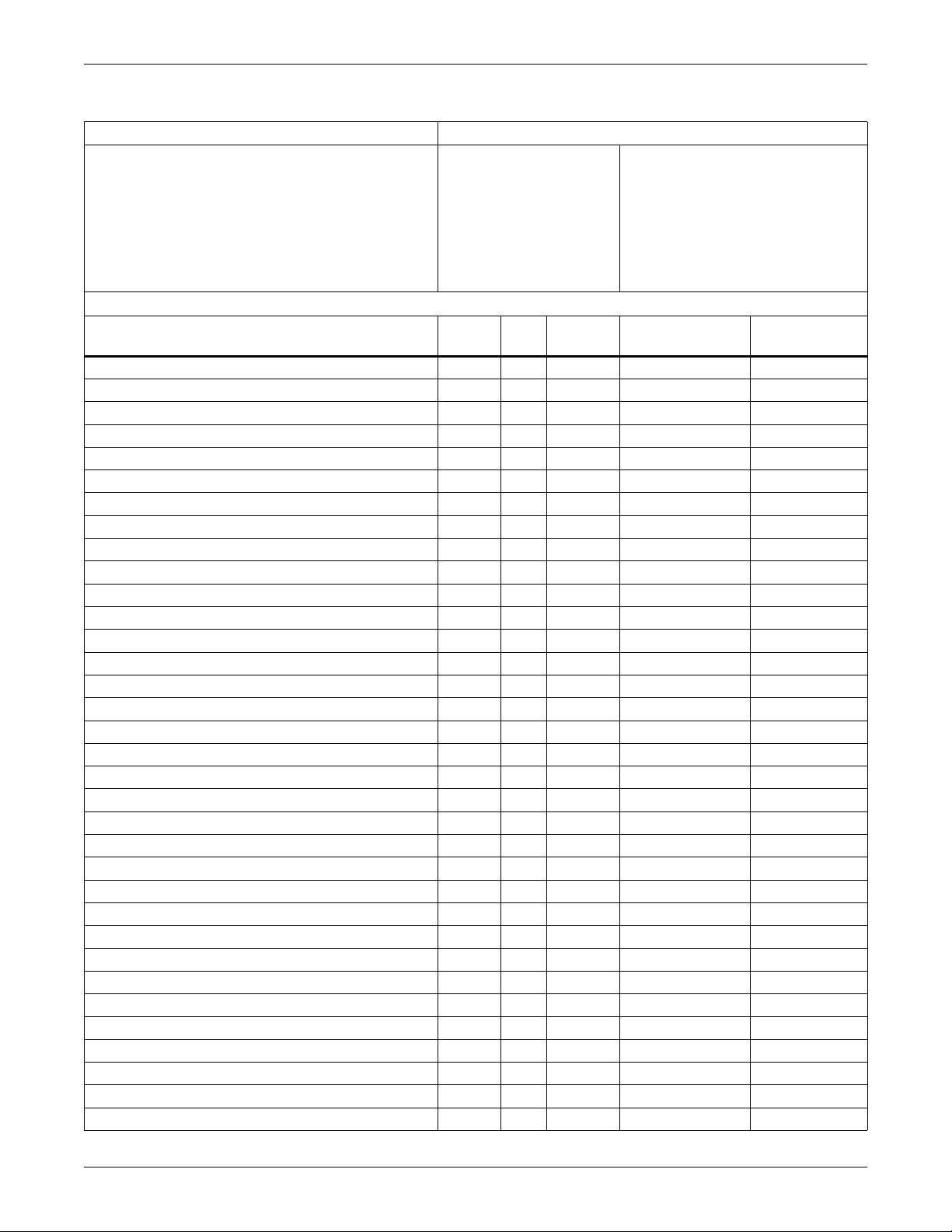
Table 1 Liebert Equipment and Compatible Liebert IntelliSlot® Cards (continued)
Refer
to
Controller /
Product Supported
Tab les:
Protocol
• Power Distribution & Power Conditioning Products
Liebert Datawave
Liebert PPC
Liebert FPC, Liebert RDC
Liebert FDC, Liebert RX
Liebert Datawave 34
™
™
™
™
,
™
33
PMP, PM2 for
33
Liebert FPC &
Liebert PPC
33
35-37 v4 IS-485S —
PMP for
Liebert FPC &
Liebert PPC 34
Liebert STS™ / Liebert STS/
™
PDU
Liebert STS2
™
PDU
™
/ Liebert STS2/
Liebert PPC
38 STS OC485-ADPT IS-WEBADPT —
39 STS2 OC485-ADPT IS-WEBADPT —
MODBUS 485 & MODBUS IP PROTOCOLS (continued)
• UPS Systems
Liebert APM
Liebert APS
Liebert GXT2
Liebert GXT3
Liebert HiNet
Liebert Nfinity
Liebert NX
Liebert NXC
Liebert NXR
Liebert NXL
(Model 40—SA, SR, SN, MM, CD)
Liebert NXL
(Model 48 and 49—SA, SR, SN,
™
™
™
™
™
™
™
™
™
™
- 60 Hz, UL version
™
- 50 Hz, CE version
40-42 —
43-45 —
46-47 —OC-485 — —
46-47 —OC-485 — —
48-49 —OC-485 — —
50-51 —OC-485 — —
52-53 —OC-485 — —
40-42 —
40-42 —
55-57 —
58-60 —
MM, CD)
™
Liebert PowerSure Interactive
Liebert PowerSure Interactive 2
Liebert Series 300
Liebert Series 600
Liebert Series 610
Liebert HiPulse
Liebert SICE 7200
Liebert SICE 7200
Liebert Npower
™
UPS 65-66 — OC485-ADPT IS-WEBADPT —
™
UPS 67-68 — OC485-ADPT IS-WEBADPT —
™
SCC UPS 69-70 — OC485-ADPT IS-WEBADPT —
™
™
™
™
61-62 —OC-485 — —
™
63-64 —OC-485 — —
71
71
SMM/SSM OC485-ADPT IS-WEBADPT —
72 SSC OC485-ADPT IS-WEBADPT —
73 IMP OC485-ADPT IS-WEBADPT —
• Battery Monitoring Products
Alber BDSU
™
74-75 — IS-485X —
Liebert IntelliSlot
Modbus 485 Card
OC485-ADPT IS-WEBADPT —Liebert FPC
OC485-ADPT IS-WEBADPT —Liebert FPC 34
IS-485L
IS-UNITY
IS-UNITY-DP
IS-UNITY
IS-UNITY-DP
IS-485L
IS-UNITY
IS-UNITY-DP
IS-485L
IS-UNITY
IS-UNITY-DP
IS-485X
IS-UNITY
IS-UNITY-DP
IS-UNITY
IS-UNITY-DP
Compatible Card Part Number
Liebert IntelliSlot
Web / Modbus 485 Card
—
—
—
—
—
—
Modbus IP /
BACnet IP
IS-IPBMS
(Modbus IP only)
IS-IPBML
IS-UNITY
IS-UNITY-DP
IS-UNITY
IS-UNITY-DP
IS-IPBML
IS-UNITY
IS-UNITY-DP
IS-IPBML
IS-UNITY
IS-UNITY-DP
IS-IPBMX
IS-UNITY
IS-UNITY-DP
IS-UNITY
IS-UNITY-DP
IS-IPBMX
(Modbus IP only)
3Liebert
®
IntelliSlot® Modbus/BACnet IP
Page 10
Liebert Equipment Compatibility - Compatibility with Liebert Equipment
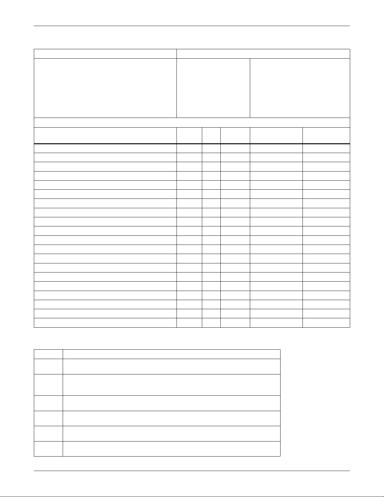
Table 1 Liebert Equipment and Compatible Liebert IntelliSlot® Cards (continued)
Refer
to
Controller /
Product Supported
Tab les:
Protocol
BACNET IP PROTOCOL
• Thermal Management Products
Liebert Challenger 3000
Liebert Challenger ITR
Liebert CRV
Liebert CW
™
™
™
™
76-82
76-82
83-86
76-82
Liebert Deluxe System/3 76-82
Liebert DS
Liebert DSE
Liebert HPC
Liebert HPM
Liebert PeX
Liebert XDC
Liebert XDP
Liebert DataMate
™
™
™
™
™
™
™
™
76-82
76-82
87-91
76-82
76-82
92-95
92-95
96
Liebert Mini-Mate2 96
™
Liebert Mini-Mate2
8 Ton 97 L8T — —
• Power Protection Products
Liebert APM 98-101 —
Liebert APS
Liebert NXC
Liebert NXR
™
™
Liebert NXL- 60Hz, UL version
(Model 40)
Liebert NXL
™
- 50Hz, CE version
(Models 48 and 49)
102-
105
98-101 —
98-101 —
106-
109
110-
113
Liebert IntelliSlot
Modbus 485 Card
Liebert
iCOM
v4
MM2 — —
IS-UNITY
IS-UNITY-DP
—
IS-UNITY
IS-UNITY-DP
IS-UNITY
IS-UNITY-DP
IS-UNITY
IS-UNITY-DP
—
—
IS-UNITY
IS-UNITY-DP
IS-UNITY-DP
IS-UNITY
Compatible Card Part Number
Liebert IntelliSlot
Web / Modbus 485 Card
——
—
—
—
—
—
—
Modbus IP /
BACnet IP
IS-IPBML
IS-UNITY
IS-UNITY-DP
IS-WEBADPT
(BACnet IP only)
IS-UNITY
IS-UNITY-DP
IS-UNITY
IS-UNITY-DP
IS-UNITY
IS-UNITY-DP
IS-UNITY
IS-UNITY-DP
IS-UNITY
IS-UNITY-DP
IS-UNITY
IS-UNITY-DP
Liebert® IntelliSlot® Modbus/BACnet IP 4
Page 11

Modbus Communications - Implementation Basics
2.0 MODBUS COMMUNICATIONS
2.1 Implementation Basics
Modbus protocol provides control and data acquisition, through query and response, between master
and slave devices. This protocol comprises the rules for communication, controlling the message
format between devices, how master and slave devices initiate communications, as well as unit
identification, message-handling and error-checking.
The Liebert IntelliSlot
multidrop configuration over EIA-485, where multiple slaves reside on a common wire or loop.
2.2 Transmission Format
The Liebert IntelliSlot 485/IP interface card supports Modbus Remote Terminal Unit (RTU)
transmission modes. See Table 2 below.
Table 2 Modbus Remote Transmission Unit settings for Liebert IntelliSlot 485/IP interface card
Physical
Port
EIA-485/422
2 wire
Transmission
®
485/IP card acts as a slave device on a network. This network can be a
Mode
RTU
Baud
Rate
9600, 19200
or 38400
Data
Bits
8None1 1
Parity
Bits
Stop
Bits
Start
Bits
2.3 Modbus Packet Format
Each Modbus packet consists of these fields:
• Device Address
• Function Code
• Data Field(s)
• Error Check Field
2.3.1 Device Address
The address field immediately follows the beginning of the frame and consists of 8-bits (RTU). This bit
indicates the user-assigned address of the slave device that is to receive the message from the
attached master device.
Each slave must be assigned a unique address. Only the addressed slave will respond to a query that
contains its address.
5Liebert
®
IntelliSlot® Modbus/BACnet IP
Page 12
Modbus Communications - RTU Framing
2.3.2 Function Code
The function code field tells the addressed slaves what function to perform. Function codes are
designed to invoke a specific action by the slave device. The function code ranges from 1 to 127.
Liebert IntelliSlot
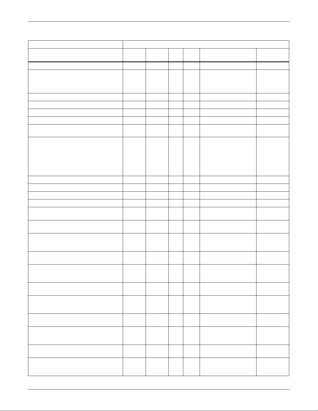
Table 3 Supported Modbus function codes
Code Function Description
01 Read Coils
02 Read Discrete Inputs
03 Read Holding Registers
04 Read Input Registers
05 Write Single Coil Write a single output to either On (1) or Off (0) mapped in coil section.
06 Write Single Register Write a value into a single holding register;
15 Write Multiple Coils Force each coil in a sequence of coils to either On or Off.
16 Write Multiple Registers Write values into a block of contiguous registers (1 to 120)
®
Modbus server supports the following Modbus function codes.
Read from 1 to 2000 contiguous status of coils managed by the server. Coils in the
response message are packed as one per bit of a byte, 1=On and 0=Off. If the requested
quantity of coils is not a multiple of 8, zeros are padded in the final byte.
Read from 1 to 2000 contiguous input status managed by the server. Discrete inputs in
the response message are packed as one per bit of a byte, 1=On and 0=Off. If the
requested number of inputs is not a multiple of 8, zeros are padded in the final byte.
Read the contents of contiguous block of 1 to 127 holding registers. Data are packed as
two bytes per register; the first byte contains the high order bits.
Read the contents of contiguous block of 1 to 127 Input registers. Data are packed as
two bytes per register; the first byte contains the high order bits.
2.3.3 Data Fields
The data field length varies, depending on whether the message is a request or a response to a packet.
This field typically contains information required by the slave device to perform the command
specified or to the response to a data request from the master device.
2.3.4 Error Check Field
The Error Check Field consists of a 16-bit (2 byte) Cyclical Redundancy Check (CRC16). It allows the
receiving device to detect a packet that has been corrupted by transmission errors.
2.4 RTU Framing
The example below shows a typical query and response from a Liebert IntelliSlot interface card. The
master device initiates a query asking Slave Device, with address 2, for holding registers starting at
holding register 40051 (offset 50) and including next two registers (three total).
Table 4 Query sample
Slave
Address
02 03 00 32 00 03 E5 FA
Function
Code
Table 5 Response sample
Slave
Address
02 03 6 1 58 00 FA 00 54 1B 0D
Function
Code
Starting Register Number of Registers CRC16
Hi Byte Lo Byte Hi Byte Lo Byte Hi Byte Lo Byte
Register CRC16
Count:
Bytes of
Data
40051 Data 40052 Data 40053 Data
Hi Byte Lo ByteHi Lo Hi Lo Hi Lo
Slave Device, with address 2, responds to Function Code 3 with 6 bytes of hexadecimal data and ends
with CRC16 checksum.
Register values: 40051 = 158 (hex) = 344 (decimal)
40052 = FA (hex) = 250 (decimal)
40053 = 54 (hex) = 84 (decimal)
Liebert® IntelliSlot® Modbus/BACnet IP 6
Page 13
Modbus 485 and Modbus IP Protocols - Thermal Management Products
3.0 MODBUS 485 AND MODBUS IP PROTOCOLS
3.1 Thermal Management Products
Table 6 Liebert Challenger 3000™, Liebert Challenger ITR™, Liebert CW™, Liebert Deluxe System/3™,
Liebert DS
Data Label
Ext Reheat Lockout 10009 - 1 Active on Alarm 1, 2, 3, 4, 5, 6
Ext Humidifier Lockout 10010 - 1 Active on Alarm 1, 2, 3, 4, 5, 6
Minimum Chilled Water Temp Set Point Enable 10013 13 1
Return Air Sensor Event Control 10019 19 1
Ext Air Sensor A Event Control 10020 20 1
Ext Compressor Lockout 10021 - 1 Active on Alarm 1, 2, 3, 4, 5, 6
System On/Off Control - 25 1
Fan State 10025 — 1
Cooling State 10026 — 1
Free Cooling State 10027 — 1
Hot Water / Hot Gas State 10028 — 1
Electric Reheat State 10029 — 1
Humidifier State 10030 — 1
Dehumidifier State 10031 — 1
Main Fan Overload 10034 — 1 Active on Alarm 1, 2, 3, 4, 5, 6
Loss of Air Flow 10035 — 1 Active on Alarm 1, 2, 3, 4, 5, 6
Ext Loss of Flow 10036 — 1 Active on Alarm 1, 2, 3, 4, 5, 6
Compressor High Head Pressure 10037 — 1 Active on Alarm 1, 2, 3, 4, 5, 6
Compressor Low Suction Pressure 10038 — 1 Active on Alarm 1, 2, 3, 4, 5, 6
Compressor Thermal Overload 10039 — 1 Active on Alarm 1, 2, 3, 4, 5, 6
Compressor Pump Down Issue 10040 — 1 Active on Alarm 1, 2, 3, 4, 5, 6
Compressor High Head Pressure 2 10041 — 1 Active on Alarm 1, 2, 3, 4, 5, 6
Compressor Low Suction Pressure 2 10042 — 1 Active on Alarm 1, 2, 3, 4, 5, 6
Compressor Thermal Overload 2 10043 — 1 Active on Alarm 1, 2, 3, 4, 5, 6
™
, Liebert DSE™, Liebert HPM™, Liebert PeX™ - Status and Coil
Controller Liebert iCOM® v4
Units with Liebert iCOM Firmware
PA1.04.033.STD or later:
Liebert Challenger 3000
Liebert Products
Units with
Liebert iCOM
Liebert HPM
Available Points
Status Coil
®
:
Number
of Bits Notes / Units Extra Notes
Liebert Challenger ITR
Liebert CW
Liebert Deluxe System/3
Liebert DS
Liebert DSE
Liebert PeX
0 = disabled
1 = enabled
0 = disabled
1 = enabled
0 = disabled
1 = enabled
0 = off
1 = on
0 = off
1 = on
0 = off
1 = on
0 = off
1 = on
0 = off
1 = on
0 = off
1 = on
0 = off
1 = on
0 = off
1 = on
1, 2, 3, 4, 5, 6
1, 2, 3, 4, 5, 6
1, 2, 3, 4, 5, 6
1, 2, 3, 4, 5, 6
1, 2, 3, 4, 5, 6
1, 2, 3, 4, 5, 6
1, 2, 3, 4, 5, 6
1, 2, 3, 4, 5, 6
1, 2, 3, 4, 5, 6
1, 2, 3, 4, 5, 6
1, 2, 3, 4, 5, 6
7Liebert
®
IntelliSlot® Modbus/BACnet IP
Page 14

Modbus 485 and Modbus IP Protocols - Thermal Management Products
Table 6 Liebert Challenger 3000™, Liebert Challenger ITR™, Liebert CW™, Liebert Deluxe System/3™,
Liebert DS
Data Label
Compressor Pump Down Issue 2 10044 — 1 Active on Alarm 1, 2, 3, 4, 5, 6
Dig Scroll Comp Over Temp 1 10045 — 1 Active on Alarm 1, 2, 3, 4, 5, 6
Dig Scroll Comp Over Temp 2 10046 — 1 Active on Alarm 1, 2, 3, 4, 5, 6
Smoke Detected 10047 — 1 Active on Alarm 1, 2, 3, 4, 5, 6
Water Under Floor 10048 — 1 Active on Alarm 1, 2, 3, 4, 5, 6
Humidifier Issue 10049 — 1 Active on Alarm 1, 2, 3, 4, 5, 6
Ext Standby Glycol Pump On 10050 — 1 Active on Alarm 1, 2, 3, 4, 5, 6
Ext Standby Unit On 10051 — 1 Active on Alarm 1, 2, 3, 4, 5, 6
Ext Condenser Pump High Water 10052 — 1 Active on Alarm 1, 2, 3, 4, 5, 6
Return Air Sensor Issue 10053 — 1 Active on Alarm 1, 2, 3, 4, 5, 6
Ext Loss of Air Blower 10055 — 1 Active on Alarm 1, 2, 3, 4, 5, 6
Humidifier Low Water 10058 — 1 Active on Alarm 1, 2, 3, 4, 5, 6
Humidifier Over Current 10059 — 1 Active on Alarm 1, 2, 3, 4, 5, 6
Ext Over Temperature 10060 — 1 Active on Alarm 1, 2, 3, 4, 5, 6
Shutdown - Loss Of Power 10061 — 1 Active on Alarm 1, 2, 3, 4, 5, 6
Supply Chilled Water Over Temp 10065 — 1 Active on Alarm 1, 2, 3, 4, 5, 6
Return Air Over Temperature 10067 — 1 Active on Alarm 1, 2, 3, 4, 5, 6
Return Air Under Temperature 10068 — 1 Active on Alarm 1, 2, 3, 4, 5, 6
High Return Humidity 10069 — 1 Active on Alarm 1, 2, 3, 4, 5, 6
Low Return Humidity 10070 — 1 Active on Alarm 1, 2, 3, 4, 5, 6
Ext Air Sensor A Over Temperature 10071 — 1 Active on Alarm 1, 2, 3, 4, 5, 6
Ext Air Sensor A Under Temperature 10072 — 1 Active on Alarm 1, 2, 3, 4, 5, 6
Ext Air Sensor A High Humidity 10073 — 1 Active on Alarm 1, 2, 3, 4, 5, 6
Ext Air Sensor A Low Humidity 10074 — 1 Active on Alarm 1, 2, 3, 4, 5, 6
Supply Chilled Water Loss of Flow 10075 — 1 Active on Alarm 1, 2, 3, 4, 5, 6
Clogged Air Filter 10076 — 1 Active on Alarm 1, 2, 3, 4, 5, 6
Supply Air Sensor Issue 10077 — 1 Active on Alarm 1, 2, 3, 4, 5, 6
Free Cooling Temp Sensor Issue 10078 — 1 Active on Alarm 1, 2, 3, 4, 5, 6
Ext Air Sensor A Issue 10079 — 1 Active on Alarm 1, 2, 3, 4, 5, 6
Fan Hours Exceeded 10080 — 1 Active on Alarm 1, 2, 3, 4, 5, 6
Compressor Hours Exceeded 1 10081 — 1 Active on Alarm 1, 2, 3, 4, 5, 6
Compressor Hours Exceeded 2 10082 — 1 Active on Alarm 1, 2, 3, 4, 5, 6
Free Cooling Valve Hours Exceeded 10083 — 1 Active on Alarm 1, 2, 3, 4, 5, 6
Electric Reheater Hours Exceeded 1 10084 — 1 Active on Alarm 1, 2, 3, 4, 5, 6
™
, Liebert DSE™, Liebert HPM™, Liebert PeX™ - Status and Coil (continued)
Controller Liebert iCOM® v4
Units with Liebert iCOM Firmware
PA1.04.033.STD or later:
Liebert Challenger 3000
Liebert Products
Units with
Liebert iCOM
Liebert HPM
®
:
Liebert Challenger ITR
Liebert CW
Liebert Deluxe System/3
Liebert DS
Liebert DSE
Liebert PeX
Available Points
Number
Status Coil
of Bits Notes / Units Extra Notes
Liebert® IntelliSlot® Modbus/BACnet IP 8
Page 15

Modbus 485 and Modbus IP Protocols - Thermal Management Products
Table 6 Liebert Challenger 3000™, Liebert Challenger ITR™, Liebert CW™, Liebert Deluxe System/3™,
Liebert DS
Data Label
Electric Reheater Hours Exceeded 2 10085 — 1 Active on Alarm 1, 2, 3, 4, 5, 6
Electric Reheater Hours Exceeded 3 10086 — 1 Active on Alarm 1, 2, 3, 4, 5, 6
Hot Water / Hot Gas Valve Hours Exceeded 10087 — 1 Active on Alarm 1, 2, 3, 4, 5, 6
Humidifier Hours Exceeded 10088 — 1 Active on Alarm 1, 2, 3, 4, 5, 6
Dehumidifier Hours Exceeded 10089 — 1 Active on Alarm 1, 2, 3, 4, 5, 6
Unit Communication Lost 10091 — 1 Active on Alarm 1, 2, 3, 4, 5, 6
Master Unit Communication Lost 10092 — 1 Active on Alarm 1, 2, 3, 4, 5, 6
Unit Code Missing 10094 — 1 Active on Alarm 1, 2, 3, 4, 5, 6
Service Required 10098 — 1 Active on Alarm 1, 2, 3, 4, 5, 6
Humidifier Control Board Not Detected 10099 — 1 Active on Alarm 1, 2, 3, 4, 5, 6
Customer Input 1 10104 — 1 Active on Alarm 1, 2, 3, 4, 5, 6
Customer Input 2 10105 — 1 Active on Alarm 1, 2, 3, 4, 5, 6
Customer Input 3 10106 — 1 Active on Alarm 1, 2, 3, 4, 5, 6
Customer Input 4 10107 — 1 Active on Alarm 1, 2, 3, 4, 5, 6
Dig Scroll Comp Discharge Temp Sensor Issue 1 10108 — 1 Active on Alarm 1, 2, 3, 4, 5, 6
Dig Scroll Comp Discharge Temp Sensor Issue 2 10109 — 1 Active on Alarm 1, 2, 3, 4, 5, 6
Supply Air Over Temperature 10209 — 1 Active on Alarm 1, 2, 3, 4, 5, 6
Supply Air Under Temperature 10210 — 1 Active on Alarm 1, 2, 3, 4, 5, 6
Ambient Air Sensor Issue 10211 — 1 Active on Alarm 2, 3, 4, 5, 6
Compressor Short Cycle 1 10212 — 1 Active on Alarm 1, 2, 3, 4, 5, 6
Compressor Short Cycle 2 10213 — 1 Active on Alarm 1, 2, 3, 4, 5, 6
Ext Free Cooling Lockout 10214 — 1 Active on Alarm 1, 2, 3, 4, 5, 6
Reheater Over Temperature 10215 — 1 Active on Alarm 1, 2, 3, 4, 5, 6
Humidifier Cylinder Worn 10216 — 1 Active on Alarm 1, 2, 3, 4, 5, 6
Humidifier Under Current 10217 — 1 Active on Alarm 1, 2, 3, 4, 5, 6
Fan Issue 10218 — 1 Active on Alarm 1, 2, 3, 4, 5, 6
Condenser TVSS Issue 10219 — 1 Active on Alarm 1, 2, 3, 4, 5, 6
Condenser VFD Issue 10220 — 1 Active on Alarm 1, 2, 3, 4, 5, 6
Condenser Issue 1 10221 — 1 Active on Alarm 1, 2, 3, 4, 5, 6
Condenser Issue 2 10222 — 1 Active on Alarm 1, 2, 3, 4, 5, 6
BMS Communications Timeout 10223 — 1 Active on Alarm 1, 2, 3, 4, 5, 6
Digital Output Board Not Detected 1 10224 — 1 Active on Alarm 1, 2, 3, 4, 5, 6
Digital Output Board Not Detected 2 10225 — 1 Active on Alarm 1, 2, 3, 4, 5, 6
Digital Output Board Not Detected 3 10226 — 1 Active on Alarm 1, 2, 3, 4, 5, 6
™
, Liebert DSE™, Liebert HPM™, Liebert PeX™ - Status and Coil (continued)
Controller Liebert iCOM® v4
Units with Liebert iCOM Firmware
PA1.04.033.STD or later:
Liebert Challenger 3000
Liebert Products
Units with
Liebert iCOM
Liebert HPM
®
:
Liebert Challenger ITR
Liebert CW
Liebert Deluxe System/3
Liebert DS
Liebert DSE
Liebert PeX
Available Points
Number
Status Coil
of Bits Notes / Units Extra Notes
9Liebert
®
IntelliSlot® Modbus/BACnet IP
Page 16

Modbus 485 and Modbus IP Protocols - Thermal Management Products
Table 6 Liebert Challenger 3000™, Liebert Challenger ITR™, Liebert CW™, Liebert Deluxe System/3™,
Liebert DS
Data Label
RAM Battery Issue 10227 — 1 Active on Alarm 1, 2, 3, 4, 5, 6
Water Leakage Detector Sensor Issue 10228 — 1 Active on Alarm 1, 2, 3, 4, 5, 6
External Fire Detected 10229 — 1 Active on Alarm 1, 2, 3, 4, 5, 6
Chilled Water Control Valve Failure 1 10230 — 1 Active on Alarm 1, 2, 3, 4, 5, 6
Chilled Water Control Valve Failure 2 10231 — 1 Active on Alarm 1, 2, 3, 4, 5, 6
Unit Off 10232 — 1 Active on Alarm 1, 2, 3, 4, 5, 6
Unit On 10233 — 1 Active on Alarm 1, 2, 3, 4, 5, 6
Unit Partial Shutdown 10234 — 1 Active on Alarm 1, 2, 3, 4, 5, 6
Unit Shutdown 10235 — 1 Active on Alarm 1, 2, 3, 4, 5, 6
High Power Shutdown 10236 — 1 Active on Alarm 1, 2, 3, 4, 5, 6
Unit Standby 10237 — 1 Active on Alarm 1, 2, 3, 4, 5, 6
Maintenance Due 10238 — 1 Active on Alarm 1, 2, 3, 4, 5, 6
Maintenance Completed 10239 — 1 Active on Alarm 1, 2, 3, 4, 5, 6
Compressor Low Pressure Transducer Issue 1 10240 — 1 Active on Alarm 1, 2, 3, 4, 5, 6
Compressor Low Pressure Transducer Issue 2 10241 — 1 Active on Alarm 1, 2, 3, 4, 5, 6
Compressor High Pressure Transducer Issue 1 10242 — 1 Active on Alarm 1, 2, 3, 4, 5, 6
Compressor High Pressure Transducer Issue 2 10243 — 1 Active on Alarm 1, 2, 3, 4, 5, 6
Compressor Capacity Reduced 10244 — 1 Active on Alarm 1, 2, 3, 4, 5, 6
Dew Point Over Temperature 10345 — 1 Active on Alarm 2, 3, 4, 5, 6
Dew Point Under Temperature 10346 — 1 Active on Alarm 2, 3, 4, 5, 6
Ext Dew Point Over Temperature 10347 — 1 Active on Alarm 2, 3, 4, 5, 6
Ext Dew Point Under Temperature 10348 — 1 Active on Alarm 2, 3, 4, 5, 6
Compressor Superheat Over Threshold 1 10349 — 1 Active on Alarm 2, 3, 4, 5, 6
Compressor Superheat Over Threshold 2 10350 — 1 Active on Alarm 2, 3, 4, 5, 6
Unspecified General Event 10351 — 1 Active on Alarm 2, 3, 4, 5, 6
Remote Sensor Average Over Temperature 10352 — 1 Active on Alarm 2, 3, 4, 5, 6
Remote Sensor Average Under Temperature 10353 — 1 Active on Alarm 2, 3, 4, 5, 6
Remote Sensor System Average Over Temperature 10354 — 1 Active on Alarm 2, 3, 4, 5, 6
Remote Sensor System Average Under Temperature 10355 — 1 Active on Alarm 2, 3, 4, 5, 6
Remote Sensor Over Temperature 1 10356 — 1 Active on Alarm 2, 3, 4, 5, 6
Remote Sensor Over Temperature 2 10357 — 1 Active on Alarm 2, 3, 4, 5, 6
Remote Sensor Over Temperature 3 10358 — 1 Active on Alarm 2, 3, 4, 5, 6
Remote Sensor Over Temperature 4 10359 — 1 Active on Alarm 2, 3, 4, 5, 6
Remote Sensor Over Temperature 5 10360 — 1 Active on Alarm 2, 3, 4, 5, 6
™
, Liebert DSE™, Liebert HPM™, Liebert PeX™ - Status and Coil (continued)
Controller Liebert iCOM® v4
Units with Liebert iCOM Firmware
PA1.04.033.STD or later:
Liebert Challenger 3000
Liebert Products
Units with
Liebert iCOM
Liebert HPM
®
:
Liebert Challenger ITR
Liebert CW
Liebert Deluxe System/3
Liebert DS
Liebert DSE
Liebert PeX
Available Points
Number
Status Coil
of Bits Notes / Units Extra Notes
Liebert® IntelliSlot® Modbus/BACnet IP 10
Page 17
Modbus 485 and Modbus IP Protocols - Thermal Management Products
Table 6 Liebert Challenger 3000™, Liebert Challenger ITR™, Liebert CW™, Liebert Deluxe System/3™,
Liebert DS
Data Label
Remote Sensor Over Temperature 6 10361 — 1 Active on Alarm 2, 3, 4, 5, 6
Remote Sensor Over Temperature 7 10362 — 1 Active on Alarm 2, 3, 4, 5, 6
Remote Sensor Over Temperature 8 10363 — 1 Active on Alarm 2, 3, 4, 5, 6
Remote Sensor Over Temperature 9 10364 — 1 Active on Alarm 2, 3, 4, 5, 6
Remote Sensor Over Temperature 10 10365 — 1 Active on Alarm 2, 3, 4, 5, 6
Remote Sensor Under Temperature 1 10366 — 1 Active on Alarm 2, 3, 4, 5, 6
Remote Sensor Under Temperature 2 10367 — 1 Active on Alarm 2, 3, 4, 5, 6
Remote Sensor Under Temperature 3 10368 — 1 Active on Alarm 2, 3, 4, 5, 6
Remote Sensor Under Temperature 4 10369 — 1 Active on Alarm 2, 3, 4, 5, 6
Remote Sensor Under Temperature 5 10370 — 1 Active on Alarm 2, 3, 4, 5, 6
Remote Sensor Under Temperature 6 10371 — 1 Active on Alarm 2, 3, 4, 5, 6
Remote Sensor Under Temperature 7 10372 — 1 Active on Alarm 2, 3, 4, 5, 6
Remote Sensor Under Temperature 8 10373 — 1 Active on Alarm 2, 3, 4, 5, 6
Remote Sensor Under Temperature 9 10374 — 1 Active on Alarm 2, 3, 4, 5, 6
Remote Sensor Under Temperature 10 10375 — 1 Active on Alarm 2, 3, 4, 5, 6
Remote Sensor Issue 1 10376 — 1 Active on Alarm 1, 2, 3, 4, 5, 6
Remote Sensor Issue 2 10377 — 1 Active on Alarm 2, 3, 4, 5, 6
Remote Sensor Issue 3 10378 — 1 Active on Alarm 2, 3, 4, 5, 6
Remote Sensor Issue 4 10379 — 1 Active on Alarm 2, 3, 4, 5, 6
Remote Sensor Issue 5 10380 — 1 Active on Alarm 2, 3, 4, 5, 6
Remote Sensor Issue 6 10381 — 1 Active on Alarm 2, 3, 4, 5, 6
Remote Sensor Issue 7 10382 — 1 Active on Alarm 2, 3, 4, 5, 6
Remote Sensor Issue 8 10383 — 1 Active on Alarm 2, 3, 4, 5, 6
Remote Sensor Issue 9 10384 — 1 Active on Alarm 2, 3, 4, 5, 6
Remote Sensor Issue 10 10385 — 1 Active on Alarm 2, 3, 4, 5, 6
Air Economizer Emergency Override 10386 — 1 Active on Alarm 2, 3, 4, 5, 6
Air Economizer Reduced Airflow 10387 — 1 Active on Alarm 2, 3, 4, 5, 6
Temperature Control Sensor Issue 10388 — 1 Active on Alarm 2, 3, 4, 5, 6
EEV Unspecified General Event 10488 — 1 Active on Alarm 4, 5
Static Pressure Sensor Issue 10489 — 1 Active on Alarm 3, 5, 6
High Static Pressure 10490 — 1 Active on Alarm 3, 5, 6
Low Static Pressure 10491 — 1 Active on Alarm 3, 5, 6
Pump Unspecified General Event 10492 — 1 Active on Alarm 4, 5
Condenser Unit Unspecified General Event 10493 — 1 Active on Alarm 3, 4, 5, 6
™
, Liebert DSE™, Liebert HPM™, Liebert PeX™ - Status and Coil (continued)
Controller Liebert iCOM® v4
Units with Liebert iCOM Firmware
PA1.04.033.STD or later:
Liebert Challenger 3000
Liebert Products
Units with
Liebert iCOM
Liebert HPM
®
:
Liebert Challenger ITR
Liebert CW
Liebert Deluxe System/3
Liebert DS
Liebert DSE
Liebert PeX
Available Points
Number
Status Coil
of Bits Notes / Units Extra Notes
11 Liebert® IntelliSlot® Modbus/BACnet IP
Page 18
Modbus 485 and Modbus IP Protocols - Thermal Management Products
Table 6 Liebert Challenger 3000™, Liebert Challenger ITR™, Liebert CW™, Liebert Deluxe System/3™,
Liebert DS
Data Label
Condenser Circuit Unspecified General Event 10494 — 1 Active on Alarm 3, 4, 5, 6
Input Undervoltage 1 10500 — 1 Active on Alarm 6
Input Undervoltage 2 10501 — 1 Active on Alarm 6
Input Undervoltage 3 10502 — 1 Active on Alarm 6
Input Undervoltage 4 10503 — 1 Active on Alarm 6
Input Undervoltage 5 10504 — 1 Active on Alarm 6
Input Undervoltage 6 10505 — 1 Active on Alarm 6
Return Humidity Sensor Issue 10600 — 1 Active on Alarm 5, 6
Compressor Low Differential Pressure Lockout 1 10601 — 1 Active on Alarm 5
Compressor Low Differential Pressure Lockout 2 10602 — 1 Active on Alarm 5
Airflow Sensor Issue 10603 — 1 Active on Alarm 5, 6
Ext Air Damper Position Issue 10604 — 1 Active on Alarm 5, 6
Ext Power Source A Failure 10605 — 1 Active on Alarm 5, 6
Ext Power Source B Failure 10606 — 1 Active on Alarm 5, 6
Static Pressure Sensor Out of Range 10607 — 1 Active on Alarm 5, 6
Fluid Temperature Sensor Issue 1 10608 — 1 Active on Alarm 6
Fluid Temperature Sensor Issue 2 10609 — 1 Active on Alarm 6
Fluid Flow Sensor Issue 1 10610 — 1 Active on Alarm 6
Fluid Flow Sensor Issue 2 10611 — 1 Active on Alarm 6
Mixed Mode Lockout 10620 — 1 Active on Alarm 5
™
, Liebert DSE™, Liebert HPM™, Liebert PeX™ - Status and Coil (continued)
Controller Liebert iCOM® v4
Units with Liebert iCOM Firmware
PA1.04.033.STD or later:
Liebert Challenger 3000
Liebert Products
Units with
Liebert iCOM
Liebert HPM
®
:
Liebert Challenger ITR
Liebert CW
Liebert Deluxe System/3
Liebert DS
Liebert DSE
Liebert PeX
Available Points
Number
Status Coil
of Bits Notes / Units Extra Notes
Table 7 Extra notes key to Table 6
Number
1
2
3
4
5
6
Description
This point is supported on:
iCOM controller version 1.04.042.STD
This point is supported on:
iCOM controller version 2.00.11R for US
iCOM controller version 2.00.12R (for Japan and China – language corrections only)
This point is supported on:
iCOM controller version 2.01.23R
This point is supported on:
iCOM controller version 2.02.16R
This point is supported on:
iCOM controller version 2.03.27.07R
This point is supported on:
iCOM controller version 2.01.32.02R
Liebert® IntelliSlot® Modbus/BACnet IP 12
Page 19

Modbus 485 and Modbus IP Protocols - Thermal Management Products
Table 8 Liebert Challenger 3000™, Liebert Challenger ITR™, Liebert CW™, Liebert Deluxe System/3™,
Liebert DS
Data Label
Free Cooling Internal Control Mode 30017 40017 1 —
Humidity Proportional Control Type 30018 40018 1 —
Fan Speed Maximum Set Point 30019 40019 1 — % 1, 2, 3, 4, 5, 6
Supply Air Temperature Set Point 30020 40020 1 — deg C 1
Supply Air Temperature Set Point 30733 40733 1 — deg F 1
Free Cooling Internal Temperature Delta 30021 40021 1 10 deg C 1, 2, 3, 4, 5, 6
Free Cooling Internal Temperature Delta 30734 40734 1 10 deg F 1, 2, 3, 4, 5, 6
Minimum Chilled Water Temp Set Point 30022 40022 1 10 deg C 1, 2, 3, 4, 5, 6
Minimum Chilled Water Temp Set Point 30735 40735 1 10 deg F 1, 2, 3, 4, 5, 6
Air Temperature Set Point 30023 40023 1 10 deg C 1, 2, 3, 4, 5, 6
Air Temperature Set Point 30736 40736 1 10 deg F 1, 2, 3, 4, 5, 6
Air Temperature Proportional Band 30024 40024 1 10 deg C 1, 2, 3, 4, 5, 6
Air Temperature Proportional Band 30737 40737 1 10 deg F 1, 2, 3, 4, 5, 6
Air Temperature Dead Band 30025 40025 1 10 deg C 1, 2, 3, 4, 5, 6
Air Temperature Dead Band 30738 40738 1 10 deg F 1, 2, 3, 4, 5, 6
Air Temperature Control Integration Time 30026 40026 1 10 min 1, 2, 3, 4, 5, 6
Humidity Set Point 30027 40027 1 — % RH 1, 2, 3, 4, 5, 6
Humidity Proportional Band 30028 40028 1 — % RH 1, 2, 3, 4, 5, 6
Humidity Proportional Control Integration
Time
Humidity Dead Band 30030 40030 1 10 % RH 1, 2, 3, 4, 5, 6
Auto Restart Delay 30031 40031 1 — sec 1, 2, 3, 4, 5, 6
Air Temperature Control Type 30033 40033 1 —
BMS Timeout Period 30045 40045 1 — min 1, 2, 3, 4, 5, 6
Return Air Over Temp Threshold 30050 40050 1 10 deg C 1, 2, 3, 4, 5, 6
Return Air Over Temp Threshold 30739 40739 1 10 deg F 1, 2, 3, 4, 5, 6
Return Air Under Temp Threshold 30051 40051 1 10 deg C 1, 2, 3, 4, 5, 6
Return Air Under Temp Threshold 30740 40740 1 10 deg F 1, 2, 3, 4, 5, 6
Ext Air Sensor A Over Temp Threshold 30052 40052 1 10 deg C 1, 2, 3, 4, 5, 6
Ext Air Sensor A Over Temp Threshold 30741 40741 1 10 deg F 1, 2, 3, 4, 5, 6
Ext Air Sensor A Under Temp Threshold 30053 40053 1 10 deg C 1, 2, 3, 4, 5, 6
Ext Air Sensor A Under Temp Threshold 30742 40742 1 10 deg F 1, 2, 3, 4, 5, 6
High Return Humidity Threshold 30054 40054 1 10 % RH 1, 2, 3, 4, 5, 6
Low Return Humidity Threshold 30055 40055 1 10 % RH 1, 2, 3, 4, 5, 6
Ext Air Sensor A High Humidity Threshold 30056 40056 1 10 % RH 1, 2, 3, 4, 5, 6
Ext Air Sensor A Low Humidity Threshold 30057 40057 1 10 % RH 1, 2, 3, 4, 5, 6
Fan Hours Threshold 30070 40070 1 — hr 1, 2, 3, 4, 5, 6
™
, Liebert DSE™, Liebert HPM™, Liebert PeX™ - Input and Holding
Controller Liebert iCOM v4
Input
Register
30029 40029 1 10 min 1, 2, 3, 4, 5, 6
Holding
Register
# of
Reg. Scale Notes / Units
0 = Disabled
1 = Contact
2 = Value
0 = Relative
1 = Compensated
2 = Predictive
0 = Proportional
1 = Prop+Integral
3 = Intelligent
Extra
Notes
1
1
1, 2, 3, 4, 5, 6
13 Liebert® IntelliSlot® Modbus/BACnet IP
Page 20

Modbus 485 and Modbus IP Protocols - Thermal Management Products
Table 8 Liebert Challenger 3000™, Liebert Challenger ITR™, Liebert CW™, Liebert Deluxe System/3™,
Liebert DS
Data Label
Compressor Hours Threshold 1 30071 40071 1 — hr 1, 2, 3, 4, 5, 6
Compressor Hours Threshold 2 30072 40072 1 — hr 1, 2, 3, 4, 5, 6
Humidifier Hours Threshold 30073 40073 1 — hr 1, 2, 3, 4, 5, 6
Dehumidifier Hours Threshold 30074 40074 1 — hr 1, 2, 3, 4, 5, 6
Free Cooling Valve Hours Threshold 30075 40075 1 — hr 1, 2, 3, 4, 5, 6
Electric Reheater Hours Threshold 1 30076 40076 1 — hr 1, 2, 3, 4, 5, 6
Electric Reheater Hours Threshold 2 30077 40077 1 — hr 1, 2, 3, 4, 5, 6
Electric Reheater Hours Threshold 3 30078 40078 1 — hr 1, 2, 3, 4, 5, 6
Hot Water / Hot Gas Valve Hours Threshold 30079 40079 1 — hr 1, 2, 3, 4, 5, 6
System Operating State 30100 — 1 —
System Status 30102 — 1 —
Fan Speed 30103 — 1 — % 1, 2, 3, 4, 5, 6
Compressor Utilization 30104 — 1 — % 1
Free Cooling Valve Open Position 30105 — 1 — % 1, 2, 3, 4, 5, 6
Reheat Utilization 30106 — 1 — % 1, 2, 3, 4, 5, 6
Humidifier Utilization 30107 — 1 — % 1, 2, 3, 4, 5, 6
Dehumidifier Utilization 30108 — 1 — % 1, 2, 3, 4, 5, 6
Free Cooling Status 30109 — 1 —
Return Air Temperature 30110 — 1 10 deg C 1, 2, 3, 4, 5, 6
Return Air Temperature 30743 — 1 10 deg F 1, 2, 3, 4, 5, 6
Supply Air Temperature 30112 — 1 10 deg C 1, 2, 3, 4, 5, 6
Supply Air Temperature 30744 — 1 10 deg F 1, 2, 3, 4, 5, 6
Supply Air Temperature Set Point 30113 — 1 — deg C 1
Supply Air Temperature Set Point 30745 — 1 — deg F 1
Free Cooling Fluid Temperature 30115 — 1 10 deg C 1, 2, 3, 4, 5, 6
Free Cooling Fluid Temperature 30746 — 1 10 deg F 1, 2, 3, 4, 5, 6
Ext Air Sensor A Temperature 30116 — 1 10 deg C 1, 2, 3, 4, 5, 6
Ext Air Sensor A Temperature 30747 — 1 10 deg F 1, 2, 3, 4, 5, 6
Ext Air Sensor B Temperature 30117 — 1 10 deg C 1, 2, 3, 4, 5, 6
Ext Air Sensor B Temperature 30748 — 1 10 deg F 1, 2, 3, 4, 5, 6
Ext Air Sensor C Temperature 30118 — 1 10 deg C 1, 2, 3, 4, 5, 6
Ext Air Sensor C Temperature 30749 — 1 10 deg F 1, 2, 3, 4, 5, 6
Dig Scroll Comp Discharge Temp 1 30119 — 1 — deg C 1, 2, 3, 4, 5, 6
Dig Scroll Comp Discharge Temp 1 30750 — 1 — deg F 1, 2, 3, 4, 5, 6
Dig Scroll Comp Discharge Temp 2 30120 — 1 — deg C 1, 2, 3, 4, 5, 6
™
, Liebert DSE™, Liebert HPM™, Liebert PeX™ - Input and Holding (continued)
Controller Liebert iCOM v4
Input
Register
Holding
Register
# of
Reg. Scale Notes / Units
0 = off
1 = on
2 = standby
1 = Normal Operation
2 = StartUp
8 = Normal with Warning
16 = Normal with Alarm
32 = Abnormal Operation
0 = off
2 = on
3 = No Support
1, 2, 3, 4, 5, 6
1, 2, 3, 4, 5, 6
1, 2, 3, 4, 5, 6
Extra
Notes
Liebert® IntelliSlot® Modbus/BACnet IP 14
Page 21

Modbus 485 and Modbus IP Protocols - Thermal Management Products
Table 8 Liebert Challenger 3000™, Liebert Challenger ITR™, Liebert CW™, Liebert Deluxe System/3™,
Liebert DS
Data Label
Dig Scroll Comp Discharge Temp 2 30751 — 1 — deg F 1, 2, 3, 4, 5, 6
Return Humidity 30130 — 1 10 % RH 1, 2, 3, 4, 5, 6
Ext Air Sensor A Humidity 30132 — 1 10 % RH 1, 2, 3, 4, 5, 6
Ext Air Sensor B Humidity 30133 — 1 10 % RH 1, 2, 3, 4, 5, 6
Ext Air Sensor C Humidity 30134 — 1 10 % RH 1, 2, 3, 4, 5, 6
Fan Hours 30141 40141 1 — hr 1, 2, 3, 4, 5, 6
Compressor Hours 1 30142 40142 1 — hr 1, 2, 3, 4, 5, 6
Compressor Hours 2 30143 40143 1 — hr 1, 2, 3, 4, 5, 6
Humidifier Hours 30144 40144 1 — hr 1, 2, 3, 4, 5, 6
Dehumidifier Hours 30145 40145 1 — hr 1, 2, 3, 4, 5, 6
Free Cooling Valve Hours 30146 40146 1 — hr 1, 2, 3, 4, 5, 6
Electric Reheater Hours 1 30147 40147 1 — hr 1, 2, 3, 4, 5, 6
Electric Reheater Hours 2 30148 40148 1 — hr 1, 2, 3, 4, 5, 6
Electric Reheater Hours 3 30149 40149 1 — hr 1, 2, 3, 4, 5, 6
Hot Water / Hot Gas Valve Hours 30150 40150 1 — hr 1, 2, 3, 4, 5, 6
Today's High Air Temperature 30151 — 1 10 deg C 1, 2, 3, 4, 5, 6
Today's High Air Temperature 30752 — 1 10 deg F 1, 2, 3, 4, 5, 6
Today's Low Air Temperature 30153 — 1 10 deg C 1, 2, 3, 4, 5, 6
Today's Low Air Temperature 30753 — 1 10 deg F 1, 2, 3, 4, 5, 6
Today's High Humidity 30155 — 1 10 % RH 1, 2, 3, 4, 5, 6
Today's Low Humidity 30157 — 1 10 % RH 1, 2, 3, 4, 5, 6
Server Class 30257 — 1 —
Today's High Air Temperature Time 30258 — 2 - Seconds since Midnight 1, 2, 3, 4, 5, 6
Today's Low Air Temperature Time 30260 — 2 - Seconds since Midnight 1, 2, 3, 4, 5, 6
Supply Air Temperature Sensor Control 30262 40262 1 —
Return Air Temperature Set Point 30263 40263 1 — deg C 1
Return Air Temperature Set Point 30754 40754 1 — deg F 1
Return Humidity Set Point 30264 40264 1 — % RH 1
Today's High Humidity Time 30265 — 2 — Seconds since Midnight 1, 2, 3, 4, 5, 6
Today's Low Humidity Time 30267 — 2 — Seconds since Midnight 1, 2, 3, 4, 5, 6
Fixed Compressor State 1 30269 — 1 —
Fixed Compressor State 2 30270 — 1 —
Compressor Capacity Control State 1 30271 — 1 —
Compressor Capacity Control State 2 30272 — 1 —
™
, Liebert DSE™, Liebert HPM™, Liebert PeX™ - Input and Holding (continued)
Controller Liebert iCOM v4
Input
Register
Holding
Register
# of
Reg. Scale Notes / Units
1 = UPS
2 = AIR
3 = PMP
4 = PDU
0 = Disabled
1 = Limit
2 = Control
3 = Temp Only
0 = off
1 = on
0 = off
1 = on
0 = off
1 = on
0 = off
1 = on
1, 2, 3, 4, 5, 6
1, 2, 3, 4, 5, 6
1, 2, 3, 4, 5, 6
1, 2, 3, 4, 5, 6
1, 2, 3, 4, 5, 6
Extra
Notes
1
15 Liebert® IntelliSlot® Modbus/BACnet IP
Page 22
Modbus 485 and Modbus IP Protocols - Thermal Management Products
Table 8 Liebert Challenger 3000™, Liebert Challenger ITR™, Liebert CW™, Liebert Deluxe System/3™,
Liebert DS
Data Label
Infrared Humidifier Flush Rate 30273 40273 1 — % 1, 2, 3, 4, 5, 6
Fan Control Mode 30274 40274 1 —
Analog Input Reading 1 30275 — 1 100 — 1, 2, 3, 4, 5, 6
Analog Input Reading 2 30276 — 1 100 — 1, 2, 3, 4, 5, 6
Analog Input Reading 3 30277 — 1 100 — 1, 2, 3, 4, 5, 6
Analog Input Reading 4 30278 — 1 100 — 1, 2, 3, 4, 5, 6
System Control Mode 30280 — 1 —
System Operating State Reason 30281 — 1 —
Maintenance Ramp 30282 — 1 — % 1, 2, 3, 4, 5, 6
Calculated Next Maintenance Month 30283 — 1 — 1, 2, 3, 4, 5, 6
Calculated Next Maintenance Year 30284 — 1 — 1, 2, 3, 4, 5, 6
Hot Water / Hot Gas Valve Open Position 30285 — 1 — % 1, 2, 3, 4, 5, 6
Maintenance Tracking State 30286 — 1 —
Customer Input 1 - Event Control 30287 40287 1 —
Customer Input 1 - Event Type 30288 40288 1 —
Customer Input 2 - Event Control 30289 40289 1 —
Customer Input 2 - Event Type 30290 40290 1 —
Customer Input 3 - Event Control 30291 40291 1 —
Customer Input 3 - Event Type 30292 40292 1 —
Customer Input 4 - Event Control 30293 40293 1 —
Customer Input 4 - Event Type 30294 40294 1 —
Ext Free Cooling Lockout - Event Control 30295 40295 1 —
Ext Free Cooling Lockout - Event Type 30296 40296 1 —
™
, Liebert DSE™, Liebert HPM™, Liebert PeX™ - Input and Holding (continued)
Controller Liebert iCOM v4
Input
Register
Holding
Register
# of
Reg. Scale Notes / Units
0 = Auto
1 = Manual
2 = Economy
4 = Delta
0 = Internal (Auto)
1 = External (Manual)
0 = Reason Unknown
1 = Network Display
2 = Alarm
3 = Schedule
4 = Remote System
5 = External Input
6 = Local Display
0 = off
1 = on
0 = disabled
1 = enabled
0 = Message
1 = Warning
2 = Alarm
0 = disabled
1 = enabled
0 = Message
1 = Warning
2 = Alarm
0 = disabled
1 = enabled
0 = Message
1 = Warning
2 = Alarm
0 = disabled
1 = enabled
0 = Message
1 = Warning
2 = Alarm
0 = disabled
1 = enabled
0 = Message
1 = Warning
2 = Alarm
1, 2, 3, 4, 5, 6
1, 2, 3, 4, 5, 6
1, 2, 3, 4, 5, 6
1, 2, 3, 4, 5, 6
1, 2, 3, 4, 5, 6
1, 2, 3, 4, 5, 6
1, 2, 3, 4, 5, 6
1, 2, 3, 4, 5, 6
1, 2, 3, 4, 5, 6
1, 2, 3, 4, 5, 6
1, 2, 3, 4, 5, 6
1, 2, 3, 4, 5, 6
1, 2, 3, 4, 5, 6
Extra
Notes
1
Liebert® IntelliSlot® Modbus/BACnet IP 16
Page 23

Modbus 485 and Modbus IP Protocols - Thermal Management Products
Table 8 Liebert Challenger 3000™, Liebert Challenger ITR™, Liebert CW™, Liebert Deluxe System/3™,
Liebert DS
Data Label
Ext Condenser Pump High Water - Event
Control
Ext Condenser Pump High Water - Event
Type
Ext Standby Glycol Pump On - Event
Control
Ext Standby Glycol Pump On - Event Type 30300 40300 1 —
Ext Standby Unit On - Event Control 30301 40301 1 —
Ext Standby Unit On - Event Type 30302 40302 1 —
Ext Humidifier Lockout - Event Control 30303 40303 1 —
Ext Humidifier Lockout - Event Type 30304 40304 1 —
Ext Loss of Flow - Event Control 30305 40305 1 —
Ext Loss of Flow - Event Type 30306 40306 1 —
Ext Over Temperature - Event Control 30307 40307 1 —
Ext Over Temperature - Event Type 30308 40308 1 —
Ext Reheat Lockout - Event Control 30309 40309 1 —
Ext Reheat Lockout - Event Type 30310 40310 1 —
High Power Shutdown - Event Control 30311 40311 1 —
High Power Shutdown - Event Type 30312 40312 1 —
Humidifier Issue - Event Control 30313 40313 1 —
Humidifier Issue - Event Type 30314 40314 1 —
Master Unit Communication Lost - Event
Control
Master Unit Communication Lost - Event
Type
™
, Liebert DSE™, Liebert HPM™, Liebert PeX™ - Input and Holding (continued)
Controller Liebert iCOM v4
Input
Register
30297 40297 1 —
30298 40298 1 —
30299 40299 1 —
30315 40315 1 —
30316 40316 1 —
Holding
Register
# of
Reg. Scale Notes / Units
0 = disabled
1 = enabled
0 = Message
1 = Warning
2 = Alarm
0 = disabled
1 = enabled
0 = Message
1 = Warning
2 = Alarm
0 = disabled
1 = enabled
0 = Message
1 = Warning
2 = Alarm
0 = disabled
1 = enabled
0 = Message
1 = Warning
2 = Alarm
0 = disabled
1 = enabled
0 = Message
1 = Warning
2 = Alarm
0 = disabled
1 = enabled
0 = Message
1 = Warning
2 = Alarm
0 = disabled
1 = enabled
0 = Message
1 = Warning
2 = Alarm
0 = disabled
1 = enabled
0 = Message
1 = Warning
2 = Alarm
0 = disabled
1 = enabled
0 = Message
1 = Warning
2 = Alarm
0 = disabled
1 = enabled
0 = Message
1 = Warning
2 = Alarm
1, 2, 3, 4, 5, 6
1, 2, 3, 4, 5, 6
1, 2, 3, 4, 5, 6
1, 2, 3, 4, 5, 6
1, 2, 3, 4, 5, 6
1, 2, 3, 4, 5, 6
1, 2, 3, 4, 5, 6
1, 2, 3, 4, 5, 6
1, 2, 3, 4, 5, 6
1, 2, 3, 4, 5, 6
1, 2, 3, 4, 5, 6
1, 2, 3, 4, 5, 6
1, 2, 3, 4, 5, 6
1, 2, 3, 4, 5, 6
1, 2, 3, 4, 5, 6
1, 2, 3, 4, 5, 6
1, 2, 3, 4, 5, 6
1, 2, 3, 4, 5, 6
1, 2, 3, 4, 5, 6
1, 2, 3, 4, 5, 6
Extra
Notes
17 Liebert® IntelliSlot® Modbus/BACnet IP
Page 24

Modbus 485 and Modbus IP Protocols - Thermal Management Products
Table 8 Liebert Challenger 3000™, Liebert Challenger ITR™, Liebert CW™, Liebert Deluxe System/3™,
Liebert DS
Data Label
Service Required - Event Control 30317 40317 1 —
Service Required - Event Type 30318 40318 1 —
Shutdown - Loss Of Power - Event Control 30319 40319 1 —
Shutdown - Loss Of Power - Event Type 30320 40320 1 —
Smoke Detected - Event Control 30321 40321 1 —
Smoke Detected - Event Type 30322 40322 1 —
Water Under Floor - Event Control 30323 40323 1 —
Water Under Floor - Event Type 30324 40324 1 —
Ext Compressor Lockout - Event Control 30325 40325 1 —
Ext Compressor Lockout - Event Type 30326 40326 1 —
Clogged Air Filter - Event Control 30327 40327 1 —
Clogged Air Filter - Event Type 30328 40328 1 —
Ext Loss of Air Blower - Event Control 30329 40329 1 —
Ext Loss of Air Blower - Event Type 30330 40330 1 —
Compressor High Head Pressure - Event
Control 1
Compressor High Head Pressure - Event
Control 2
Compressor High Head Pressure - Event
Type 1
Compressor High Head Pressure - Event
Type 2
Compressor Low Suction Pressure - Event
Control 1
Compressor Low Suction Pressure - Event
Control 2
™
, Liebert DSE™, Liebert HPM™, Liebert PeX™ - Input and Holding (continued)
Controller Liebert iCOM v4
Input
Register
30331 40331 1 —
30332 40332 1 —
30333 40333 1 —
30334 40334 1 —
30335 40335 1 —
30336 40336 1 —
Holding
Register
# of
Reg. Scale Notes / Units
0 = disabled
1 = enabled
0 = Message
1 = Warning
2 = Alarm
0 = disabled
1 = enabled
0 = Message
1 = Warning
2 = Alarm
0 = disabled
1 = enabled
0 = Message
1 = Warning
2 = Alarm
0 = disabled
1 = enabled
0 = Message
1 = Warning
2 = Alarm
0 = disabled
1 = enabled
0 = Message
1 = Warning
2 = Alarm
0 = disabled
1 = enabled
0 = Message
1 = Warning
2 = Alarm
0 = disabled
1 = enabled
0 = Message
1 = Warning
2 = Alarm
0 = disabled
1 = enabled
0 = disabled
1 = enabled
0 = Message
1 = Warning
2 = Alarm
0 = Message
1 = Warning
2 = Alarm
0 = disabled
1 = enabled
0 = disabled
1 = enabled
1, 2, 3, 4, 5, 6
1, 2, 3, 4, 5, 6
1, 2, 3, 4, 5, 6
1, 2, 3, 4, 5, 6
1, 2, 3, 4, 5, 6
1, 2, 3, 4, 5, 6
1, 2, 3, 4, 5, 6
1, 2, 3, 4, 5, 6
1, 2, 3, 4, 5, 6
1, 2, 3, 4, 5, 6
1, 2, 3, 4, 5, 6
1, 2, 3, 4, 5, 6
1, 2, 3, 4, 5, 6
1, 2, 3, 4, 5, 6
1, 2, 3, 4, 5, 6
1, 2, 3, 4, 5, 6
1, 2, 3, 4, 5, 6
1, 2, 3, 4, 5, 6
1, 2, 3, 4, 5, 6
1, 2, 3, 4, 5, 6
Extra
Notes
Liebert® IntelliSlot® Modbus/BACnet IP 18
Page 25

Modbus 485 and Modbus IP Protocols - Thermal Management Products
Table 8 Liebert Challenger 3000™, Liebert Challenger ITR™, Liebert CW™, Liebert Deluxe System/3™,
Liebert DS
Data Label
Compressor Low Suction Pressure - Event
Type 1
Compressor Low Suction Pressure - Event
Type 2
Compressor Pump Down Issue - Event
Control 1
Compressor Pump Down Issue - Event
Control 2
Compressor Pump Down Issue - Event
Type 1
Compressor Pump Down Issue - Event
Type 2
Compressor Short Cycle - Event Control 1 30343 40343 1 —
Compressor Short Cycle - Event Control 2 30344 40344 1 —
Compressor Short Cycle - Event Type 1 30345 40345 1 —
Compressor Short Cycle - Event Type 2 30346 40346 1 —
Compressor Thermal Overload - Event
Control 1
Compressor Thermal Overload - Event
Control 2
Compressor Thermal Overload - Event
Type 1
Compressor Thermal Overload - Event
Type 2
Dig Scroll Comp Discharge Over Temp Event Ctrl 1
Dig Scroll Comp Discharge Over Temp Event Ctrl 2
Dig Scroll Comp Discharge Over Temp Event Type 1
Dig Scroll Comp Discharge Over Temp Event Type 2
Ext Air Sensor A High Humidity - Event
Control
Ext Air Sensor A High Humidity - Event
Type
™
, Liebert DSE™, Liebert HPM™, Liebert PeX™ - Input and Holding (continued)
Controller Liebert iCOM v4
Input
Register
30337 40337 1 —
30338 40338 1 —
30339 40339 1 —
30340 40340 1 —
30341 40341 1 —
30342 40342 1 —
30347 40347 1 —
30348 40348 1 —
30349 40349 1 —
30350 40350 1 —
30351 40351 1 —
30352 40352 1 —
30353 40353 1 —
30354 40354 1 —
30355 40355 1 —
30356 40356 1 —
Holding
Register
# of
Reg. Scale Notes / Units
0 = Message
1 = Warning
2 = Alarm
0 = Message
1 = Warning
2 = Alarm
0 = disabled
1 = enabled
0 = disabled
1 = enabled
0 = Message
1 = Warning
2 = Alarm
0 = Message
1 = Warning
2 = Alarm
0 = disabled
1 = enabled
0 = disabled
1 = enabled
0 = Message
1 = Warning
2 = Alarm
0 = Message
1 = Warning
2 = Alarm
0 = disabled
1 = enabled
0 = disabled
1 = enabled
0 = Message
1 = Warning
2 = Alarm
0 = Message
1 = Warning
2 = Alarm
0 = disabled
1 = enabled
0 = disabled
1 = enabled
0 = Message
1 = Warning
2 = Alarm
0 = Message
1 = Warning
2 = Alarm
0 = disabled
1 = enabled
0 = Message
1 = Warning
2 = Alarm
1, 2, 3, 4, 5, 6
1, 2, 3, 4, 5, 6
1, 2, 3, 4, 5, 6
1, 2, 3, 4, 5, 6
1, 2, 3, 4, 5, 6
1, 2, 3, 4, 5, 6
1, 2, 3, 4, 5, 6
1, 2, 3, 4, 5, 6
1, 2, 3, 4, 5, 6
1, 2, 3, 4, 5, 6
1, 2, 3, 4, 5, 6
1, 2, 3, 4, 5, 6
1, 2, 3, 4, 5, 6
1, 2, 3, 4, 5, 6
1, 2, 3, 4, 5, 6
1, 2, 3, 4, 5, 6
1, 2, 3, 4, 5, 6
1, 2, 3, 4, 5, 6
1, 2, 3, 4, 5, 6
1, 2, 3, 4, 5, 6
Extra
Notes
19 Liebert® IntelliSlot® Modbus/BACnet IP
Page 26

Modbus 485 and Modbus IP Protocols - Thermal Management Products
Table 8 Liebert Challenger 3000™, Liebert Challenger ITR™, Liebert CW™, Liebert Deluxe System/3™,
Liebert DS
Data Label
Ext Air Sensor A Low Humidity - Event
Control
Ext Air Sensor A Low Humidity - Event Type 30358 40358 1 —
Ext Air Sensor A Over Temp - Event Control 30359 40359 1 —
Ext Air Sensor A Over Temp - Event Type 30360 40360 1 —
Ext Air Sensor A Under Temp - Event
Control
Ext Air Sensor A Under Temp - Event Type 30362 40362 1 —
High Return Humidity - Event Control 30363 40363 1 —
High Return Humidity - Event Type 30364 40364 1 —
Low Return Humidity - Event Control 30365 40365 1 —
Low Return Humidity - Event Type 30366 40366 1 —
Return Air Over Temp - Event Control 30367 40367 1 —
Return Air Over Temp - Event Type 30368 40368 1 —
Return Air Under Temp - Event Control 30369 40369 1 —
Return Air Under Temp - Event Type 30370 40370 1 —
Fan Hours Exceeded - Event Control 30371 40371 1 —
Fan Hours Exceeded - Event Type 30372 40372 1 —
Fan Issue - Event Control 30373 40373 1 —
Fan Issue - Event Type 30374 40374 1 —
Main Fan Overload - Event Control 30375 40375 1 —
Main Fan Overload - Event Type 30376 40376 1 —
™
, Liebert DSE™, Liebert HPM™, Liebert PeX™ - Input and Holding (continued)
Controller Liebert iCOM v4
Input
Register
30357 40357 1 —
30361 40361 1 —
Holding
Register
# of
Reg. Scale Notes / Units
0 = disabled
1 = enabled
0 = Message
1 = Warning
2 = Alarm
0 = disabled
1 = enabled
0 = Message
1 = Warning
2 = Alarm
0 = disabled
1 = enabled
0 = Message
1 = Warning
2 = Alarm
0 = disabled
1 = enabled
0 = Message
1 = Warning
2 = Alarm
0 = disabled
1 = enabled
0 = Message
1 = Warning
2 = Alarm
0 = disabled
1 = enabled
0 = Message
1 = Warning
2 = Alarm
0 = disabled
1 = enabled
0 = Message
1 = Warning
2 = Alarm
0 = disabled
1 = enabled
0 = Message
1 = Warning
2 = Alarm
0 = disabled
1 = enabled
0 = Message
1 = Warning
2 = Alarm
0 = disabled
1 = enabled
0 = Message
1 = Warning
2 = Alarm
1, 2, 3, 4, 5, 6
1, 2, 3, 4, 5, 6
1, 2, 3, 4, 5, 6
1, 2, 3, 4, 5, 6
1, 2, 3, 4, 5, 6
1, 2, 3, 4, 5, 6
1, 2, 3, 4, 5, 6
1, 2, 3, 4, 5, 6
1, 2, 3, 4, 5, 6
1, 2, 3, 4, 5, 6
1, 2, 3, 4, 5, 6
1, 2, 3, 4, 5, 6
1, 2, 3, 4, 5, 6
1, 2, 3, 4, 5, 6
1, 2, 3, 4, 5, 6
1, 2, 3, 4, 5, 6
1, 2, 3, 4, 5, 6
1, 2, 3, 4, 5, 6
Extra
Notes
1
1
Liebert® IntelliSlot® Modbus/BACnet IP 20
Page 27

Modbus 485 and Modbus IP Protocols - Thermal Management Products
Table 8 Liebert Challenger 3000™, Liebert Challenger ITR™, Liebert CW™, Liebert Deluxe System/3™,
Liebert DS
Data Label
Condenser Issue - Event Control 1 30377 40377 1 —
Condenser Issue - Event Control 2 30378 40378 1 —
Condenser Issue - Event Type 1 30379 40379 1 —
Condenser Issue - Event Type 2 30380 40380 1 —
System Event Acknowledge/Reset — 40381 1 —
Air Temperature Control Sensor 30481 40481 1 —
Supply Air Over Temp Threshold 30482 40482 1 10 deg C 2, 3, 4, 5, 6
Supply Air Over Temp Threshold 30755 40755 1 10 deg F 2, 3, 4, 5, 6
Supply Air Under Temp Threshold 30483 40483 1 10 deg C 2, 3, 4, 5, 6
Supply Air Under Temp Threshold 30756 40756 1 10 deg F 2, 3, 4, 5, 6
Outside Air Temperature 30484 — 1 10 deg C 2, 3, 4, 5, 6
Outside Air Temperature 30757 — 1 10 deg F 2, 3, 4, 5, 6
Humidity Proportional Control Type 30485 40485 1 —
Ext Air Sensor A Dew Point Temp 30486 - 1 10 deg C 2, 3, 4, 5, 6
Ext Air Sensor A Dew Point Temp 30758 - 1 10 deg F 2, 3, 4, 5, 6
Ext Dew Point Over Temp Threshold 30487 40487 1 10 deg C 2, 3, 4, 5, 6
Ext Dew Point Over Temp Threshold 30759 40759 1 10 deg F 2, 3, 4, 5, 6
Ext Dew Point Under Temp Threshold 30488 40488 1 10 deg C 2, 3, 4, 5, 6
Ext Dew Point Under Temp Threshold 30760 40760 1 10 deg F 2, 3, 4, 5, 6
Compressor Lockout 30489 40489 1 —
Main Chilled Water Valve 30491 40491 1 —
Reheater Lockout 30492 40492 1 —
Humidifier Lockout 30493 40493 1 —
Fan Control Sensor 30494 40494 1 —
Fan Speed Minimum Set Point 30495 40495 1 — % 2, 3, 4, 5, 6
Fan Speed Temperature Set Point 30497 40497 1 10 deg C 2, 3, 4, 5, 6
Fan Speed Temperature Set Point 30761 40761 1 10 deg F 2, 3, 4, 5, 6
Standby Units 30498 40498 1 — — 2, 3, 4, 5, 6
™
, Liebert DSE™, Liebert HPM™, Liebert PeX™ - Input and Holding (continued)
Controller Liebert iCOM v4
Input
Register
Holding
Register
# of
Reg. Scale Notes / Units
0 = disabled
1 = enabled
0 = disabled
1 = enabled
0 = Message
1 = Warning
2 = Alarm
0 = Message
1 = Warning
2 = Alarm
2 = Reset
4 = Acknowledge
0 = Supply
1 = Remote
2 = Return
0 = Relative
1 = Compensated
2 = Predictive
3 = Dew Point
0 = disabled
1 = enabled
0 = Valve 1
1 = Valve 2
0 = disabled
1 = enabled
0 = disabled
1 = enabled
0 = Supply
1 = Remote
2 = Return
3 = Manual
1, 2, 3, 4, 5, 6
1, 2, 3, 4, 5, 6
1, 2, 3, 4, 5, 6
1, 2, 3, 4, 5, 6
1, 2, 3, 4, 5, 6
Extra
Notes
2, 3, 4, 5, 6
2, 3, 4, 5, 6
2, 3, 4, 5, 6
2, 3, 4, 5, 6
2, 3, 4, 5, 6
2, 3, 4, 5, 6
2, 3, 4, 5, 6
21 Liebert® IntelliSlot® Modbus/BACnet IP
Page 28

Modbus 485 and Modbus IP Protocols - Thermal Management Products
Table 8 Liebert Challenger 3000™, Liebert Challenger ITR™, Liebert CW™, Liebert Deluxe System/3™,
Liebert DS
Data Label
Adjusted Humidity 30499 — 1 10 % RH 2, 3, 4, 5, 6
Return Dew Point 30500 — 1 10 deg C 2, 3, 4, 5, 6
Return Dew Point 30762 — 1 10 deg F 2, 3, 4, 5, 6
Actual Air Temperature Set Point 30501 — 1 10 deg C 2, 3, 4, 5, 6
Actual Air Temperature Set Point 30763 — 1 10 deg F 2, 3, 4, 5, 6
Actual Humidity Set Point 30502 — 1 - % RH 2, 3, 4, 5, 6
Dew Point Set Point 30503 40503 1 10 deg C 2, 3, 4, 5, 6
Dew Point Set Point 30764 40764 1 10 deg F 2, 3, 4, 5, 6
Supply Air Over/Under Temperature - Event
Control
Remote Sensor Over Temp Threshold 30505 40505 1 10 deg C 2, 3, 4, 5, 6
Remote Sensor Over Temp Threshold 30765 40765 1 10 deg F 2, 3, 4, 5, 6
Remote Sensor Under Temp Threshold 30506 40506 1 10 deg C 2, 3, 4, 5, 6
Remote Sensor Under Temp Threshold 30766 40766 1 10 deg F 2, 3, 4, 5, 6
Remote Sensor Average Temperature 30507 — 1 10 deg C 2, 3, 4, 5, 6
Remote Sensor Average Temperature 30767 — 1 10 deg F 2, 3, 4, 5, 6
Remote Sensor Maximum Temperature 30508 — 1 10 deg C 2, 3, 4, 5, 6
Remote Sensor Maximum Temperature 30768 — 1 10 deg F 2, 3, 4, 5, 6
Remote Sensor System Average
Temperature
Remote Sensor System Average
Temperature
Remote Sensor System Maximum
Temperature
Remote Sensor System Maximum
Temperature
Remote Sensor Temperature 1 30551 — 1 10 deg C 2, 3, 4, 5, 6
Remote Sensor Temperature 1 30771 — 1 10 deg F 2, 3, 4, 5, 6
Remote Sensor Temperature 2 30552 — 1 10 deg C 2, 3, 4, 5, 6
Remote Sensor Temperature 2 30772 — 1 10 deg F 2, 3, 4, 5, 6
Remote Sensor Temperature 3 30553 — 1 10 deg C 2, 3, 4, 5, 6
Remote Sensor Temperature 3 30773 — 1 10 deg F 2, 3, 4, 5, 6
Remote Sensor Temperature 4 30554 — 1 10 deg C 2, 3, 4, 5, 6
Remote Sensor Temperature 4 30774 — 1 10 deg F 2, 3, 4, 5, 6
Remote Sensor Temperature 5 30555 — 1 10 deg C 2, 3, 4, 5, 6
Remote Sensor Temperature 5 30775 — 1 10 deg F 2, 3, 4, 5, 6
Remote Sensor Temperature 6 30556 — 1 10 deg C 2, 3, 4, 5, 6
Remote Sensor Temperature 6 30776 — 1 10 deg F 2, 3, 4, 5, 6
Remote Sensor Temperature 7 30557 — 1 10 deg C 2, 3, 4, 5, 6
Remote Sensor Temperature 7 30777 — 1 10 deg F 2, 3, 4, 5, 6
Remote Sensor Temperature 8 30558 — 1 10 deg C 2, 3, 4, 5, 6
Remote Sensor Temperature 8 30778 — 1 10 deg F 2, 3, 4, 5, 6
™
, Liebert DSE™, Liebert HPM™, Liebert PeX™ - Input and Holding (continued)
Controller Liebert iCOM v4
Input
Register
30504 40504 1 —
30509 — 1 10 deg C 2, 3, 4, 5, 6
30769 — 1 10 deg F 2, 3, 4, 5, 6
30510 — 1 10 deg C 2, 3, 4, 5, 6
30770 — 1 10 deg F 2, 3, 4, 5, 6
Holding
Register
# of
Reg. Scale Notes / Units
0 = disabled
1 = enabled
Extra
Notes
2, 3, 4, 5, 6
Liebert® IntelliSlot® Modbus/BACnet IP 22
Page 29
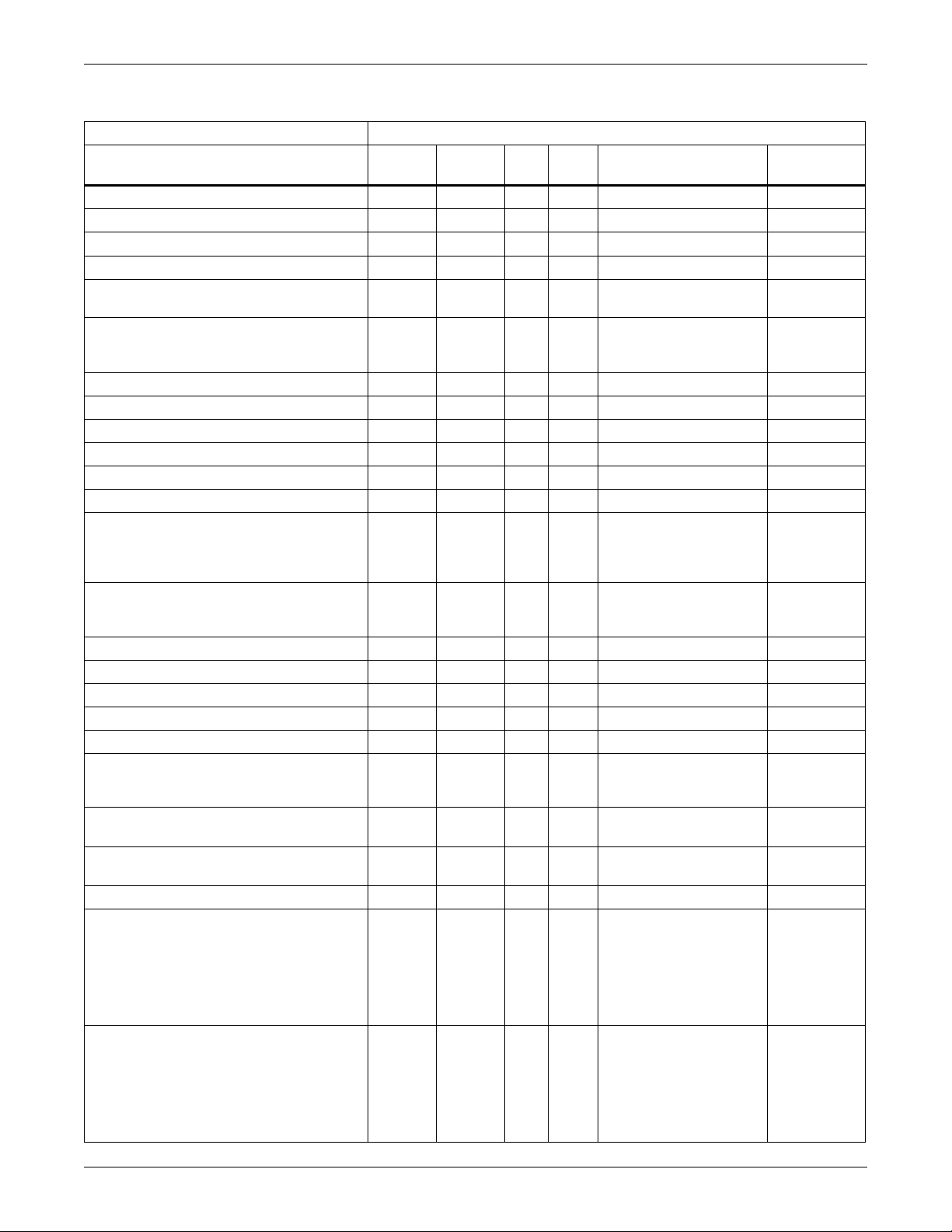
Modbus 485 and Modbus IP Protocols - Thermal Management Products
Table 8 Liebert Challenger 3000™, Liebert Challenger ITR™, Liebert CW™, Liebert Deluxe System/3™,
Liebert DS
Data Label
Remote Sensor Temperature 9 30559 — 1 10 deg C 2, 3, 4, 5, 6
Remote Sensor Temperature 9 30779 — 1 10 deg F 2, 3, 4, 5, 6
Remote Sensor Temperature 10 30560 — 1 10 deg C 2, 3, 4, 5, 6
Remote Sensor Temperature 10 30780 — 1 10 deg F 2, 3, 4, 5, 6
Air Economizer Availability 30561 — 1 —
Air Economizer Control Source 30562 40562 1 —
Chilled Water Valve Hours 30563 40563 1 — hr 2, 3, 4, 5, 6
Cooling Capacity 30564 — 1 — % 2, 3, 4, 5, 6
Cooling Control Temperature 30565 — 1 10 deg C 2, 3, 4, 5, 6
Cooling Control Temperature 30781 — 1 10 deg F 2, 3, 4, 5, 6
Fan Speed Control Temperature 30566 — 1 10 deg C 2, 3, 4, 5, 6
Fan Speed Control Temperature 30782 — 1 10 deg F 2, 3, 4, 5, 6
Free Cooling Internal Control Mode 30567 40567 1 —
Humidity Control Sensor 30667 40667 1 —
Digital Scroll Compressor Loading 1 30668 — 1 — % 3, 4, 5, 6
Digital Scroll Compressor Loading 2 30669 — 1 — % 3, 4, 5, 6
Static Pressure Set Point 30672 40672 1 10 Pa 3, 6
Unit Static Pressure 30673 — 1 10 Pa 3, 6
System Static Pressure 30674 — 1 10 Pa 3, 6
Condenser Low Noise Mode State 30675 — 1 —
Condenser Low Noise Mode Schedule
Control
Condenser Low Noise Mode Max Fan
Speed
Condenser Normal Mode Max Fan Speed 30678 40678 1 — % 3, 4, 5, 6
Condenser Low Noise Mode - Interval Days 30679 40679 1 —
Condenser Low Noise Mode - Full Days 30680 40680 1 —
™
, Liebert DSE™, Liebert HPM™, Liebert PeX™ - Input and Holding (continued)
Controller Liebert iCOM v4
Input
Register
30676 40676 1 —
30677 40677 1 — % 3, 4, 5, 6
Holding
Register
# of
Reg. Scale Notes / Units
0 = Not Available
1 = Available
0 = disabled
1 = internal
2 = external
0 = Disabled
1 = Contact
2 = Temperature
3 = Set Point
0 = Supply
1 = Remote
2 = Return
0 = Inactive
1 = Active (Interval)
2 = Active (Full Day)
0 = disabled
1 = enabled
1 = Monday
2 = Tuesday
4 = Wednesday
8 = Thursday
16 = Friday
32 = Saturday
64 = Sunday
1 = Monday
2 = Tuesday
4 = Wednesday
8 = Thursday
16 = Friday
32 = Saturday
64 = Sunday
Extra
Notes
2, 3, 4, 5, 6
2, 3, 4, 5, 6
2, 3, 4, 5, 6
3, 4, 5, 6
3, 4, 5, 6
3, 4, 5, 6
3, 4, 5, 6
3, 4, 5, 6
23 Liebert® IntelliSlot® Modbus/BACnet IP
Page 30

Modbus 485 and Modbus IP Protocols - Thermal Management Products
Table 8 Liebert Challenger 3000™, Liebert Challenger ITR™, Liebert CW™, Liebert Deluxe System/3™,
Liebert DS
Data Label
Condenser Low Noise Mode Start Time 30681 40681 2 — Seconds since Midnight 3, 4, 5, 6
Condenser Low Noise Mode Stop Time 30683 40683 2 — Seconds since Midnight 3, 4, 5, 6
Pump Hours 1 30685 40685 2 — hr 5
Pump Hours 2 30687 40687 2 — hr 5
System Input RMS A-N 1 30800 — 1 10 VAC 6
System Input RMS A-N 2 30801 — 1 10 VAC 6
System Input RMS A-N 3 30802 — 1 10 VAC 6
System Input RMS A-N 4 30803 — 1 10 VAC 6
System Input RMS A-N 5 30804 — 1 10 VAC 6
System Input RMS A-N 6 30805 — 1 10 VAC 6
System Input RMS B-N 1 30810 — 1 10 VAC 6
System Input RMS B-N 2 30811 — 1 10 VAC 6
System Input RMS B-N 3 30812 — 1 10 VAC 6
System Input RMS B-N 4 30813 — 1 10 VAC 6
System Input RMS B-N 5 30814 — 1 10 VAC 6
System Input RMS B-N 6 30815 — 1 10 VAC 6
System Input RMS C-N 1 30820 — 1 10 VAC 6
System Input RMS C-N 2 30821 — 1 10 VAC 6
System Input RMS C-N 3 30822 — 1 10 VAC 6
System Input RMS C-N 4 30823 — 1 10 VAC 6
System Input RMS C-N 5 30824 — 1 10 VAC 6
System Input RMS C-N 6 30825 — 1 10 VAC 6
System Input RMS Current Phase A 1 30830 — 1 10 A AC 6
System Input RMS Current Phase A 2 30831 — 1 10 A AC 6
System Input RMS Current Phase A 3 30832 — 1 10 A AC 6
System Input RMS Current Phase A 4 30833 — 1 10 A AC 6
System Input RMS Current Phase A 5 30834 — 1 10 A AC 6
System Input RMS Current Phase A 6 30835 — 1 10 A AC 6
System Input RMS Current Phase B 1 30840 — 1 10 A AC 6
System Input RMS Current Phase B 2 30841 — 1 10 A AC 6
System Input RMS Current Phase B 3 30842 — 1 10 A AC 6
System Input RMS Current Phase B 4 30843 — 1 10 A AC 6
System Input RMS Current Phase B 5 30844 — 1 10 A AC 6
System Input RMS Current Phase B 6 30845 — 1 10 A AC 6
System Input RMS Current Phase C 1 30850 — 1 10 A AC 6
System Input RMS Current Phase C 2 30851 — 1 10 A AC 6
System Input RMS Current Phase C 3 30852 — 1 10 A AC 6
System Input RMS Current Phase C 4 30853 — 1 10 A AC 6
System Input RMS Current Phase C 5 30854 — 1 10 A AC 6
System Input RMS Current Phase C 6 30855 — 1 10 A AC 6
™
, Liebert DSE™, Liebert HPM™, Liebert PeX™ - Input and Holding (continued)
Controller Liebert iCOM v4
Input
Register
Holding
Register
# of
Reg. Scale Notes / Units
Extra
Notes
Liebert® IntelliSlot® Modbus/BACnet IP 24
Page 31

Modbus 485 and Modbus IP Protocols - Thermal Management Products
Table 8 Liebert Challenger 3000™, Liebert Challenger ITR™, Liebert CW™, Liebert Deluxe System/3™,
Liebert DS
Data Label
Instantaneous Power 1 30860 — 1 - W 6
Instantaneous Power 2 30861 — 1 — W 6
Instantaneous Power 3 30862 — 1 — W 6
Instantaneous Power 4 30863 — 1 — W 6
Instantaneous Power 5 30864 — 1 — W 6
Instantaneous Power 6 30865 — 1 — W 6
Energy Consumption 1 30870 40870 2 — kWH 6
Energy Consumption 2 30872 40872 2 — kWH 6
Energy Consumption 3 30874 40874 2 — kWH 6
Energy Consumption 4 30876 40876 2 — kWH 6
Energy Consumption 5 30878 40878 2 — kWH 6
Energy Consumption 6 30880 40880 2 — kWH 6
Fluid Input Temperature 1 30900 — 1 10 deg C 6
Fluid Input Temperature 2 30901 — 1 10 deg C 6
Fluid Input Temperature 1 30902 — 1 10 deg F 6
Fluid Input Temperature 2 30903 — 1 10 deg F 6
Fluid Output Temperature 1 30906 — 1 10 deg F 6
Fluid Output Temperature 2 30907 — 1 10 deg F 6
Fluid Flow Rate 1 30908 — 2 10 l/min 6
Fluid Flow Rate 2 30910 — 2 10 l/min 6
Unit Cooling Load 31001 — 2 10 kW 6
Circuit Cooling Load 31003 — 2 10 kW 6
System Date and Time 39998 49998 2 — — 1, 2, 3, 4, 5, 6
™
, Liebert DSE™, Liebert HPM™, Liebert PeX™ - Input and Holding (continued)
Controller Liebert iCOM v4
Input
Register
Holding
Register
# of
Reg. Scale Notes / Units
Extra
Notes
Table 9 Extra notes key to Table 8
Number
1
2
3
4
5
6
Description
This point is supported on:
iCOM controller version 1.04.042.STD
This point is supported on:
iCOM controller version 2.00.11R for US
iCOM controller version 2.00.12R (for Japan and China – language corrections only)
This point is supported on:
iCOM controller version 2.01.23R
This point is supported on:
iCOM controller version 2.02.16R
This point is supported on:
iCOM controller version 2.03.27.07R
This point is supported on:
iCOM controller version 2.01.32.02R
25 Liebert® IntelliSlot® Modbus/BACnet IP
Page 32

Modbus 485 and Modbus IP Protocols - Thermal Management Products
Table 10 Liebert Challenger 3000™, Liebert Challenger ITR™, Liebert CW™, Liebert Deluxe System/3™,
Liebert DS
Data Label Data Description
Actual Air Temperature Set Point
Actual Humidity Set Point
Adjusted Humidity
Air Economizer Availability
Air Economizer Control Source Source of control of the air economizer.
Air Economizer Emergency
Override
Air Economizer Reduced Airflow Air economizer filter is dirty and needs to be cleaned or replaced.
Air Temperature Control
Integration Time
Air Temperature Control Sensor
Air Temperature Control Type Type of algorithm used to control the system's output air temperature.
Air Temperature Dead Band
Air Temperature Proportional Band
Air Temperature Set Point
Airflow Sensor Issue Airflow sensor is disconnected or the signal is out of range.
Ambient Air Sensor Issue Ambient air sensor is disconnected or the signal is out of range.
Analog Input Reading Generic analog input reading (unitless).
Auto Restart Delay
BMS Communications Timeout
BMS Timeout Period
Calculated Next Maintenance
Month
Calculated Next Maintenance Year
Chilled Water Control Valve Failure
Chilled Water Valve Hours
Circuit Cooling Load The amount of heat energy currently being removed by a single refrigeration circuit.
Clogged Air Filter - Event Control
Clogged Air Filter - Event Type The event type for the [Clogged Air Filter] event.
Clogged Air Filter Air filter is dirty and needs to be (cleaned or) replaced.
™
, Liebert DSE™, Liebert HPM™, Liebert PeX™ - Glossary
Controller Liebert iCOM® v4
The actual set point being used for air temperature control. This value may differ from
[Air Temperature Set Point] if compensation is applied by the control.
The actual set point being used for humidity control. This value may differ from
[Humidity Set Point] if compensation is applied by the control.
Humidity value being used for control. This value may differ from the actual measured
[Return Humidity] based on several factors which may include, but are not limited to,
selection of humidity control sensor and humidity control type.
Indicates if the outside air conditions are appropriate for cooling with the air
economizer or glycol freecooling.
Indoor room temperature has exceeded its upper threshold and the outdoor air
damper has been opened for emergency cooling.
Time value used when system is under integral air temperature control.
Sensor from which air temperature measurements will be used for cooling and heating
control.
Value that is divided evenly to form a temperature range above and below [Air
Temperature Set Point]. If measured air temperature is within this range, no heating or
cooling will occur.
Value that is divided evenly to form proportional temperature control bands above and
below [Air Temperature Set Point].
Desired air temperature. This set point is dependent upon which sensor is selected
for control.
If power is lost, the control will delay this amount of time after power is restored before
restarting the unit.
Building Management System (or external monitoring system) has not communicated
with the system within the expected timeframe.
Timeframe within which the Building Management System (or external monitoring
system) must communicate with the system to avoid a timeout.
Calculated month of the next scheduled maintenance. Used in conjunction with
[Calculated Next Maintenance Year].
Calculated year of the next scheduled maintenance. Used in conjunction with
[Calculated Next Maintenance Month].
Chilled water valve out of position. Chilled water control valve position does not match
expected value.
Operating hours for chilled water valve since last reset of this value. If operating hours
exceeds 32,000, this client will continue to display 32,000, but the iCOM display will
show the actual value.
Enable/disable the activation of the [Clogged Air Filter] event. If set to 'disabled', the
event will not be annunciated. This implies that the event will not be placed in any
active event list or in any event history list.
Liebert® IntelliSlot® Modbus/BACnet IP 26
Page 33

Modbus 485 and Modbus IP Protocols - Thermal Management Products
Table 10 Liebert Challenger 3000™, Liebert Challenger ITR™, Liebert CW™, Liebert Deluxe System/3™,
Liebert DS
Data Label Data Description
Compressor Capacity Control
Stat e
Compressor Capacity Reduced Compressor capacity has been reduced.
Compressor High Head Pressure Event Control
Compressor High Head Pressure Event Type
Compressor High Head Pressure Compressor is shut down due to high head pressure.
Compressor High Pressure
Transducer Issue
Compressor Hours Exceeded [Compressor Hours] has exceeded [Compressor Hours Threshold].
Compressor Hours Threshold Threshold value used in the [Compressor Hours Exceeded] event.
Compressor Hours
Compressor Lockout Enable/disable the use of the compressor.
Compressor Low Differential
Pressure Lockout
Compressor Low Pressure
Transducer Issue
Compressor Low Suction Pressure
- Event Control
Compressor Low Suction Pressure
- Event Type
Compressor Low Suction Pressure Compressor is shut down due to low suction pressure.
Compressor Pump Down Issue Event Control
Compressor Pump Down Issue Event Type
Compressor Pump Down Issue Unable to pump down suction-side pressure during compressor shutdown.
Compressor Short Cycle - Event
Control
Compressor Short Cycle - Event
Type
Compressor Short Cycle
Compressor Superheat Over
Threshold
Compressor Thermal Overload Event Control
Compressor Thermal Overload Event Type
Compressor Thermal Overload Compressor is shut down due to thermal overload.
™
, Liebert DSE™, Liebert HPM™, Liebert PeX™ - Glossary (continued)
Controller Liebert iCOM® v4
Compressor capacity control state. When 'ON', the cooling capacity of the compressor
has been reduced.
Enable/disable the activation of the [Compressor High Head Pressure] event. If set to
'disabled', the event will not be annunciated. This implies that the event will not be
placed in any active event list or in any event history list.
The event type for the [Compressor High Head Pressure] event.
Compressor high pressure transducer is disconnected or the signal is out of range.
Operating hours for compressor since last reset of this value. If operating hours
exceeds 32,000, this client will continue to display 32,000, but the iCOM display will
show the actual value.
Compressor exceeded maximum startup attempts due to low differential pressure.
Compressor is shutdown and has been disabled.
Compressor low pressure transducer is disconnected or the signal is out of range.
Enable/disable the activation of the [Compressor Low Suction Pressure] event. If set
to 'disabled', the event will not be annunciated. This implies that the event will not be
placed in any active event list or in any event history list.
The event type for the [Compressor Low Suction Pressure] event.
Enable/disable the activation of the [Compressor Pump Down Issue] event. If set to
'disabled', the event will not be annunciated. This implies that the event will not be
placed in any active event list or in any event history list.
The event type for the [Compressor Pump Down Issue] event.
Enable/disable the activation of the [Compressor Short Cycle] event. If set to
'disabled', the event will not be annunciated. This implies that the event will not be
placed in any active event list or in any event history list.
The event type for the [Compressor Short Cycle] event.
Compressor short cycle. A short cycle is defined as turning on and off a number of
times over a set time period.
Compressor discharge refrigerant superheat temperature has exceeded an upper
threshold.
Enable/disable the activation of the [Compressor Thermal Overload] event. If set to
'disabled', the event will not be annunciated. This implies that the event will not be
placed in any active event list or in any event history list.
The event type for the [Compressor Thermal Overload] event.
27 Liebert® IntelliSlot® Modbus/BACnet IP
Page 34

Modbus 485 and Modbus IP Protocols - Thermal Management Products
Table 10 Liebert Challenger 3000™, Liebert Challenger ITR™, Liebert CW™, Liebert Deluxe System/3™,
Liebert DS
Data Label Data Description
Compressor Utilization
Condenser Circuit Unspecified
General Event
Condenser Issue - Event Control
Condenser Issue - Event Type The event type for the [Condenser Issue] event.
Condenser Issue Condenser is not operating within its operational parameters.
Condenser Low Noise Mode - Full
Days
Condenser Low Noise Mode Interval Days
Condenser Low Noise Mode Max
Fan Speed
Condenser Low Noise Mode
Schedule Control
Condenser Low Noise Mode Start
Time
Condenser Low Noise Mode State State of condenser low noise mode scheduler control.
Condenser Low Noise Mode Stop
Time
Condenser Normal Mode Max Fan
Speed
Condenser TVSS Issue
Condenser Unit Unspecified
General Event
Condenser VFD Issue The condenser fan Variable Frequency Drive is offline.
Cooling Capacity Cooling capacity in use, expressed as a percentage of the maximum rated capacity.
Cooling Control Temperature
Cooling State Cooling operational state.
Customer Input 1 - Event Control
Customer Input 1 - Event Type The event type for the [Customer Input 1] event.
Customer Input 1 Customer Input 1
Customer Input 2 - Event Control
Customer Input 2 - Event Type The event type for the [Customer Input 2] event.
Customer Input 2 Customer Input 2
Customer Input 3 - Event Control
Customer Input 3 - Event Type The event type for the [Customer Input 3] event.
Customer Input 3 Customer Input 3
™
, Liebert DSE™, Liebert HPM™, Liebert PeX™ - Glossary (continued)
Controller Liebert iCOM® v4
Present compressor utilization expressed as a percentage of the maximum rated
capacity.
One or more unspecified condenser circuit events active. See local unit display for
further details.
Enable/disable the activation of the [Condenser Issue] event. If set to 'disabled', the
event will not be annunciated. This implies that the event will not be placed in any
active event list or in any event history list.
Days of the week selected for low noise mode full day scheduling.
Days of the week selected for low noise mode interval scheduling.
Maximum fan speed when condenser is placed in low noise mode.
Enable/disable scheduled control of condenser low noise mode.
The time of day at which the condenser will transition into low noise mode.
The time of day at which the condenser will transition out of low noise mode.
Maximum fan speed when condenser is not in low noise mode.
The condenser Transient Voltage Surge Suppressor or Surge Protection Device has
failed.
One or more unspecified condenser unit events active. See local unit display for
further details.
Temperature value being used for cooling capacity control. This value is compared
against the temperature set point to determine the amount of cooling to be applied.
Enable/disable the activation of the [Customer Input 1] event. If set to 'disabled', the
event will not be annunciated. This implies that the event will not be placed in any
active event list or in any event history list.
Enable/disable the activation of the [Customer Input 2] event. If set to 'disabled', the
event will not be annunciated. This implies that the event will not be placed in any
active event list or in any event history list.
Enable/disable the activation of the [Customer Input 3] event. If set to 'disabled', the
event will not be annunciated. This implies that the event will not be placed in any
active event list or in any event history list.
Liebert® IntelliSlot® Modbus/BACnet IP 28
Page 35

Modbus 485 and Modbus IP Protocols - Thermal Management Products
Table 10 Liebert Challenger 3000™, Liebert Challenger ITR™, Liebert CW™, Liebert Deluxe System/3™,
Liebert DS
Data Label Data Description
Customer Input 4 - Event Control
Customer Input 4 - Event Type The event type for the [Customer Input 4] event.
Customer Input 4 Customer Input 4
Dehumidifier Hours Exceeded Operating hours for the dehumidifier have exceeded the threshold.
Dehumidifier Hours Threshold Threshold value used in the [Dehumidifier Hours Exceeded] event.
Dehumidifier Hours
Dehumidifier State Dehumidifier operational state.
Dehumidifier Utilization
Dew Point Over Temperature Dew point temperature reading has exceeded the upper threshold.
Dew Point Set Point Desired dew point temperature.
Dew Point Under Temperature Dew point temperature reading has dropped below the lower threshold.
Dig Scroll Comp Discharge Over
Temp - Event Ctrl
Dig Scroll Comp Discharge Over
Temp - Event Type
Dig Scroll Comp Discharge Temp
Sensor Issue
Dig Scroll Comp Discharge Temp Digital scroll compressor discharge temperature.
Dig Scroll Comp Over Temp
Digital Output Board Not Detected Digital output board is required to be connected, but no signal is detected.
Digital Scroll Compressor Loading
EEV Unspecified General Event
Electric Reheat State Electric reheater operational state.
Electric Reheater Hours Exceeded [Electric Reheater Hours] has exceeded [Electric Reheaters Hours Threshold].
Electric Reheater Hours Threshold Threshold value used in the [Electric Reheater Hours Exceeded] event.
Electric Reheater Hours
Energy Consumption Energy consumption since the last reset of this value.
Ext Air Damper Position Issue
Ext Air Sensor A Dew Point Temp Dew point temperature as measured by external air sensor A.
Ext Air Sensor A Event Control
Ext Air Sensor A High Humidity Event Control
Ext Air Sensor A High Humidity Event Type
™
, Liebert DSE™, Liebert HPM™, Liebert PeX™ - Glossary (continued)
Controller Liebert iCOM® v4
Enable/disable the activation of the [Customer Input 4] event. If set to 'disabled', the
event will not be annunciated. This implies that the event will not be placed in any
active event list or in any event history list.
Operating hours for dehumidifier since last reset of this value. If operating hours
exceeds 32,000, this client will continue to display 32,000, but the iCOM display will
show the actual value.
Present dehumidifier utilization expressed as a percentage of the maximum rated
capacity.
Enable/disable the activation of the [Dig Scroll Comp Discharge Over Temp] event.
The event type for the [Dig Scroll Comp Discharge Over Temp] event.
Digital scroll compressor discharge temperature sensor is disconnected or the signal
is out of range.
Digital scroll compressor is shut down due to head temperature exceeding an upper
threshold.
Present digital scroll compressor utilization expressed as a percentage of the
maximum rated capacity.
One or more unspecified electronic expansion valve events active. See local unit
display for further details.
Operating hours for electric reheater since last reset of this value. If operating hours
exceeds 32,000, this client will continue to display 32,000, but the iCOM display will
show the actual value.
Air damper position does not match expected value, as indicated by an external input
signal.
Enable/disable the activation of events related to measurements by the external air
sensor A.
Enable/disable the activation of the [Ext Air Sensor A High Humidity] event. If set to
'disabled', the event will not be annunciated. This implies that the event will not be
placed in any active event list or in any event history list.
The event type for the [Ext Air Sensor A High Humidity] event.
29 Liebert® IntelliSlot® Modbus/BACnet IP
Page 36

Modbus 485 and Modbus IP Protocols - Thermal Management Products
Table 10 Liebert Challenger 3000™, Liebert Challenger ITR™, Liebert CW™, Liebert Deluxe System/3™,
Liebert DS
Data Label Data Description
Ext Air Sensor A High Humidity
Threshold
Ext Air Sensor A High Humidity [Ext Air Sensor A Humidity] has exceeded [Ext Air Sensor A High Humidity Threshold].
Ext Air Sensor A Humidity Relative humidity as measured by external air sensor A.
Ext Air Sensor A Issue The external air sensor A is disconnected or the signal is out of range.
Ext Air Sensor A Low Humidity Event Control
Ext Air Sensor A Low Humidity Event Type
Ext Air Sensor A Low Humidity
Threshold
Ext Air Sensor A Low Humidity
Ext Air Sensor A Over Temp Event Control
Ext Air Sensor A Over Temp Event Type
Ext Air Sensor A Over Temp
Threshold
Ext Air Sensor A Over
Temperature
Ext Air Sensor A Temperature Air temperature as measured by external air sensor A.
Ext Air Sensor A Under Temp Event Control
Ext Air Sensor A Under Temp Event Type
Ext Air Sensor A Under Temp
Threshold
Ext Air Sensor A Under
Temperature
Ext Air Sensor B Humidity Relative humidity as measured by external air sensor B.
Ext Air Sensor B Temperature Air temperature as measured by external air sensor B.
Ext Air Sensor C Humidity Relative humidity as measured by external air sensor C.
Ext Air Sensor C Temperature Air temperature as measured by external air sensor C.
Ext Compressor Lockout - Event
Control
Ext Compressor Lockout - Event
Type
Ext Compressor Lockout The compressor is shut down and disabled by an external input signal.
Ext Condenser Pump High Water Event Control
Ext Condenser Pump High Water Event Type
Ext Condenser Pump High Water High water is detected in the condenser, as indicated by an external input signal.
™
, Liebert DSE™, Liebert HPM™, Liebert PeX™ - Glossary (continued)
Controller Liebert iCOM® v4
Threshold value used in the [External Air Sensor A High Humidity] event.
Enable/disable the activation of the [Ext Air Sensor A Low Humidity] event. If set to
'disabled', the event will not be annunciated. This implies that the event will not be
placed in any active event list or in any event history list.
The event type for the [Ext Air Sensor A Low Humidity] event.
Threshold value used in the [External Air Sensor A Low Humidity] event.
[Ext Air Sensor A Humidity] has dropped below [Ext Air Sensor A Low Humidity
Threshold].
Enable/disable the activation of the [External Air Sensor A Over Temperature] event. If
set to 'disabled', the event will not be annunciated. This implies that the event will not
be placed in any active event list or in any event history list.
The event type for the [External Air Sensor A Over Temperature] event.
Threshold value used in the [External Air Sensor A Over Temperature] event.
[Ext Air Sensor A Temperature] has exceeded [External Air Sensor A Over Temp
Threshold].
Enable/disable the activation of the [Ext Air Sensor A Under Temperature] event. If set
to 'disabled', the event will not be annunciated. This implies that the event will not be
placed in any active event list or in any event history list.
The event type for the [Ext Air Sensor A Under Temperature] event.
Threshold value used in the [External Air Sensor A Under Temperature] event.
[Ext Air Sensor A Temperature] has dropped below [Ext Air Sensor A Under Temp
Threshold].
Enable/disable the activation of the [Ext Compressor Lockout] event. If set to
'disabled', the event will not be annunciated. This implies that the event will not be
placed in any active event list or in any event history list.
The event type for the [Ext Compressor Lockout] event.
Enable/disable the activation of the [Ext Condenser Pump High Water] event. If set to
'disabled', the event will not be annunciated. This implies that the event will not be
placed in any active event list or in any event history list.
The event type for the [Ext Condenser Pump High Water] event.
Liebert® IntelliSlot® Modbus/BACnet IP 30
Page 37

Modbus 485 and Modbus IP Protocols - Thermal Management Products
Table 10 Liebert Challenger 3000™, Liebert Challenger ITR™, Liebert CW™, Liebert Deluxe System/3™,
Liebert DS
Data Label Data Description
Ext Dew Point Over Temp
Threshold
Ext Dew Point Over Temperature
Ext Dew Point Under Temp
Threshold
Ext Dew Point Under Temperature
Ext Free Cooling Lockout - Event
Control
Ext Free Cooling Lockout - Event
Type
Ext Free Cooling Lockout Free cooling is disabled by an external input signal.
Ext Humidifier Lockout - Event
Control
Ext Humidifier Lockout - Event
Type
Ext Humidifier Lockout The humidifier is shut down and disabled by an external input signal.
Ext Loss of Air Blower - Event
Control
Ext Loss of Air Blower - Event Type The event type for the [Ext Loss of Air Blower] event.
Ext Loss of Air Blower Loss of air blower is detected, as indicated by an external input signal.
Ext Loss of Flow - Event Control
Ext Loss of Flow - Event Type The event type for the [Ext Loss of Flow] event.
Ext Loss of Flow Loss of flow is detected, as indicated by an external input signal.
Ext Over Temperature - Event
Control
Ext Over Temperature - Event
Type
Ext Over Temperature A temperature has exceeded its threshold, as indicated by an external input signal.
Ext Power Source A Failure Unit main power source A failure, as indicated by an external input signal.
Ext Power Source B Failure Unit main power source B failure, as indicated by an external input signal.
Ext Reheat Lockout - Event
Control
Ext Reheat Lockout - Event Type The event type for the [Ext Reheat Lockout] event.
Ext Reheat Lockout The reheater is shut down and disabled by an external input signal.
Ext Standby Glycol Pump On Event Control
™
, Liebert DSE™, Liebert HPM™, Liebert PeX™ - Glossary (continued)
Controller Liebert iCOM® v4
Threshold value used in the [Ext Dew Point Over Temperature] event.
At least one dew point temperature reading ([Ext Air Sensor A Dew Point Temp], [Ext
Air Sensor B Dew Point Temp]...) has exceeded [Ext Dew Point Over Temp
Threshold].
Threshold value used in the [Ext Dew Point Under Temperature] event.
At least one dew point temperature reading ([Ext Air Sensor A Dew Point Temp], [Ext
Air Sensor B Dew Point Temp]...) has dropped below [Ext Dew Point Under Temp
Threshold].
Enable/disable the activation of the [Ext Free Cooling Lockout] event. If set to
'disabled', the event will not be annunciated. This implies that the event will not be
placed in any active event list or in any event history list.
The event type for the [Ext Free Cooling Lockout] event.
Enable/disable the activation of the [Ext Humidifier Lockout] event. If set to 'disabled',
the event will not be annunciated. This implies that the event will not be placed in any
active event list or in any event history list.
The event type for the [Ext Humidifier Lockout] event.
Enable/disable the activation of the [Ext Loss of Air Blower] event. If set to 'disabled',
the event will not be annunciated. This implies that the event will not be placed in any
active event list or in any event history list.
Enable/disable the activation of the [Ext Loss of Flow] event. If set to 'disabled', the
event will not be annunciated. This implies that the event will not be placed in any
active event list or in any event history list.
Enable/disable the activation of the [Ext Over Temperature] event. If set to 'disabled',
the event will not be annunciated. This implies that the event will not be placed in any
active event list or in any event history list.
The event type for the [Ext Over Temperature] event.
Enable/disable the activation of the [Ext Reheat Lockout] event. If set to 'disabled', the
event will not be annunciated. This implies that the event will not be placed in any
active event list or in any event history list.
Enable/disable the activation of the [Ext Standby Glycol Pump On] event. If set to
'disabled', the event will not be annunciated. This implies that the event will not be
placed in any active event list or in any event history list.
31 Liebert® IntelliSlot® Modbus/BACnet IP
Page 38

Modbus 485 and Modbus IP Protocols - Thermal Management Products
Table 10 Liebert Challenger 3000™, Liebert Challenger ITR™, Liebert CW™, Liebert Deluxe System/3™,
Liebert DS
Data Label Data Description
Ext Standby Glycol Pump On Event Type
Ext Standby Glycol Pump On The standby glycol pump is on, as indicated by an external input signal.
Ext Standby Unit On - Event
Control
Ext Standby Unit On - Event Type The event type for the [Ext Standby Unit On] event.
Ext Standby Unit On Standby unit is on, as indicated by an external input signal.
External Fire Detected Fire detected, as indicated by an external input signal.
Fan Control Mode Fan control mode.
Fan Control Sensor Sensor to be used for fan speed control.
Fan Hours Exceeded - Event
Control
Fan Hours Exceeded - Event Type The event type for the [Fan Hours Exceeded] event.
Fan Hours Exceeded Operating hours for the unit blower fan have exceeded the threshold.
Fan Hours Threshold Threshold value used in the [Fan Hours Exceeded] event.
Fan Hours
Fan Issue - Event Control
Fan Issue - Event Type The event type for the [Fan Issue] event.
Fan Issue One or more fans are not operating within their operational parameters.
Fan Speed Control Temperature
Fan Speed Maximum Set Point
Fan Speed Minimum Set Point Minimum fan speed.
Fan Speed Temperature Set Point
Fan Speed Fan speed expressed as a percentage of the maximum rated speed.
Fan State Fan operational state.
Fixed Compressor State Fixed compressor operational state.
Fluid Flow Rate Flow rate of fluid used for cooling.
Fluid Flow Sensor Issue The fluid flow sensor is disconnected or the signal is out of range.
Fluid Input Temperature Temperature of the fluid entering the cooling coil.
Fluid Output Temperature Temperature of the fluid exiting the cooling coil.
Fluid Temperature Sensor Issue The fluid temperature sensor is disconnected or the signal is out of range.
Free Cooling Fluid Temperature Free cooling fluid temperature.
Free Cooling Internal Control
Mode
Free Cooling Internal Control
Mode
™
, Liebert DSE™, Liebert HPM™, Liebert PeX™ - Glossary (continued)
Controller Liebert iCOM® v4
The event type for the [Ext Standby Glycol Pump On] event.
Enable/disable the activation of the [Ext Standby Unit On] event. If set to 'disabled', the
event will not be annunciated. This implies that the event will not be placed in any
active event list or in any event history list.
Enable/disable the activation of the [Fan Hours Exceeded] event. If set to 'disabled',
the event will not be annunciated. This implies that the event will not be placed in any
active event list or in any event history list.
Operating hours for fan since last reset of this value. If operating hours exceeds
32,000, this client will continue to display 32,000, but the iCOM display will show the
actual value.
Enable/disable the activation of the [Fan Issue] event. If set to 'disabled', the event will
not be annunciated. This implies that the event will not be placed in any active event
list or in any event history list.
Temperature value being used for fan speed control. This value is compared against
the fan speed temperature set point to determine the fan speed.
Maximum fan speed. This value may only be modified if iCOM is enabled to allow fan
speed changes by the BMS.
If fan is in decoupled mode and not under manual control, the fan speed will vary
depending on the delta between the selected fan control sensor temperature and this
set point.
Free cooling internal control mode
Free cooling internal control mode
Liebert® IntelliSlot® Modbus/BACnet IP 32
Page 39

Modbus 485 and Modbus IP Protocols - Thermal Management Products
Table 10 Liebert Challenger 3000™, Liebert Challenger ITR™, Liebert CW™, Liebert Deluxe System/3™,
Liebert DS
Data Label Data Description
Free Cooling Internal Temperature
Delta
Free Cooling State Free cooling operational state.
Free Cooling Status Free cooling status.
Free Cooling Temp Sensor Issue The free cooling fluid temperature sensor is disconnected or the signal is out of range.
Free Cooling Valve Hours
Exceeded
Free Cooling Valve Hours
Threshold
Free Cooling Valve Hours
Free Cooling Valve Open Position Free cooling valve open position.
High Power Shutdown - Event
Control
High Power Shutdown - Event
Type
High Power Shutdown Supply to high power components has been shutdown.
High Return Humidity - Event
Control
High Return Humidity - Event Type The event type for the [High Return Humidity] event.
High Return Humidity Threshold Threshold value used in the [High Return Humidity] event.
High Return Humidity Return air high humidity event.
High Static Pressure High static pressure event.
Hot Water / Hot Gas State Hot water / hot gas operational state.
Hot Water / Hot Gas Valve Hours
Exceeded
Hot Water / Hot Gas Valve Hours
Threshold
Hot Water / Hot Gas Valve Hours
Hot Water / Hot Gas Valve Open
Position
Humidifier Control Board Not
Detected
Humidifier Cylinder Worn Humidifier cylinder is not operating properly and needs to be replaced.
Humidifier Hours Exceeded Operating hours for the humidifier have exceeded the threshold.
Humidifier Hours Threshold Threshold value used in the [Humidifier Hours Exceeded] event.
Humidifier Hours
Humidifier Issue - Event Control
Humidifier Issue - Event Type The event type for the [Humidifier Issue] event.
™
, Liebert DSE™, Liebert HPM™, Liebert PeX™ - Glossary (continued)
Controller Liebert iCOM® v4
Minimum temperature delta required between supply fluid and internal ambient air
temperatures in order to enable free cooling.
[Free Cooling Valve Hours] has exceeded [Free Cooling Valve Hours Threshold].
Threshold value used in the [Free Cooling Valve Hours Exceeded] event.
Operating hours for free cooling valve since last reset of this value. If operating hours
exceeds 32,000, this client will continue to display 32,000, but the iCOM display will
show the actual value.
Enable/disable the activation of the [High Power Shutdown] event. If set to 'disabled',
the event will not be annunciated. This implies that the event will not be placed in any
active event list or in any event history list.
The event type for the [High Power Shutdown] event.
Enable/disable the activation of the [High Return Humidity] event. If set to 'disabled',
the event will not be annunciated. This implies that the event will not be placed in any
active event list or in any event history list.
[Hot Water / Hot Gas Valve Hours] has exceeded [Hot Water / Hot Gas Valve Hours
Threshold].
Threshold value used in the [Hot Water / Hot Gas Valve Hours Exceeded] event.
Operating hours for hot water / hot gas valve since last reset of this value. If operating
hours exceeds 32,000, this client will continue to display 32,000, but the iCOM display
will show the actual value.
Hot water / hot gas valve open position.
Humidifier control board is required to be connected, but no signal is detected.
Operating hours for humidifier since last reset of this value. If operating hours
exceeds 32,000, this client will continue to display 32,000, but the iCOM display will
show the actual value.
Enable/disable the activation of the [Humidifier Issue] event. If set to 'disabled', the
event will not be annunciated. This implies that the event will not be placed in any
active event list or in any event history list.
33 Liebert® IntelliSlot® Modbus/BACnet IP
Page 40

Modbus 485 and Modbus IP Protocols - Thermal Management Products
Table 10 Liebert Challenger 3000™, Liebert Challenger ITR™, Liebert CW™, Liebert Deluxe System/3™,
Liebert DS
Data Label Data Description
Humidifier Issue Humidifier issue detected, causing it to be locked out.
Humidifier Lockout Enable/disable the use of the humidifier.
Humidifier Low Water The water level in the humidifier has dropped below its threshold.
Humidifier Over Current The electrical current to the humidifier has exceeded its upper threshold.
Humidifier State Humidifier operational state.
Humidifier Under Current The electrical current to the humidifier has dropped below its lower threshold.
Humidifier Utilization
Humidity Control Sensor
Humidity Dead Band
Humidity Proportional Band
Humidity Proportional Control
Integration Time
Humidity Proportional Control Type Type of algorithm to use for proportional control of output humidity.
Humidity Proportional Control Type Type of algorithm to use for proportional control of output humidity.
Humidity Set Point Desired relative humidity.
Infrared Humidifier Flush Rate
Input Undervoltage One or more of the input phase voltages has dropped below the limit.
Instantaneous Power Total electrical power currently being consumed.
Loss of Air Flow No air flow through the unit due to failure of all fans.
Low Return Humidity - Event
Control
Low Return Humidity - Event Type The event type for the [Low Return Humidity] event.
Low Return Humidity Threshold Threshold value used in the [Low Return Humidity] event.
Low Return Humidity Return air low humidity event.
Low Static Pressure Low static pressure event.
Main Chilled Water Valve The primary valve in a dual valve chilled water system.
Main Fan Overload - Event Control
Main Fan Overload - Event Type The event type for the [Main Fan Overload] event.
Main Fan Overload Main fan is shut down due to thermal overload.
Maintenance Completed Maintenance has been completed on the unit.
Maintenance Due The calculated maintenance date has been reached.
Maintenance Ramp
Maintenance Tracking State Maintenance tracking operational state.
Master Unit Communication Lost Event Control
™
, Liebert DSE™, Liebert HPM™, Liebert PeX™ - Glossary (continued)
Controller Liebert iCOM® v4
Present humidifier utilization expressed as a percentage of the maximum rated
capacity.
Sensor from which humidity measurements will be used for humidification and
dehumidification control.
Value that is divided evenly to form a range above and below [Humidity Set Point]. If
measured humidity is within this range, no humidification or dehumidification will
occur.
Value that is divided evenly to form proportional humidity control bands above and
below [Humidity Set Point].
Time value used to add an integral term to proportional humidity control. If set to 0,
time will not be a factor in the proportional control algorithm.
A multiple of an internal time constant that determines the flush duration of the infrared
humidifier water pan.
Enable/disable the activation of the [Low Return Humidity] event. If set to 'disabled',
the event will not be annunciated. This implies that the event will not be placed in any
active event list or in any event history list.
Enable/disable the activation of the [Main Fan Overload] event. If set to 'disabled', the
event will not be annunciated. This implies that the event will not be placed in any
active event list or in any event history list.
The ratio of operations performed to the calculated operations available between
maintenance intervals.
Enable/disable the activation of the [Master Unit Communication Lost] event. If set to
'disabled', the event will not be annunciated. This implies that the event will not be
placed in any active event list or in any event history list.
Liebert® IntelliSlot® Modbus/BACnet IP 34
Page 41

Modbus 485 and Modbus IP Protocols - Thermal Management Products
Table 10 Liebert Challenger 3000™, Liebert Challenger ITR™, Liebert CW™, Liebert Deluxe System/3™,
Liebert DS
Data Label Data Description
Master Unit Communication Lost Event Type
Master Unit Communication Lost Communication with master unit has been lost.
Minimum Chilled Water Temp Set
Point Enable
Minimum Chilled Water Temp Set
Point
Mixed Mode Lockout
Outside Air Temperature Ambient outside air temperature.
Pump Hours Operating hours for pump since last reset of this value.
Pump Unspecified General Event One or more unspecified pump events active. See local unit display for further details.
RAM Battery Issue RAM or RAM backup battery is not operating correctly.
Reheat Utilization
Reheater Lockout Enable/disable the use of the reheater.
Reheater Over Temperature The temperature of the reheater has exceeded its threshold.
Remote Sensor Average Over
Temperature
Remote Sensor Average
Temperature
Remote Sensor Average Under
Temperature
Remote Sensor Issue Remote sensor is disconnected or the signal is out of range.
Remote Sensor Maximum
Temperature
Remote Sensor Over Temp
Threshold
Remote Sensor Over Temperature [Remote Sensor Temperature] has exceeded [Remote Sensor Over Temp Threshold].
Remote Sensor System Average
Over Temperature
Remote Sensor System Average
Temperature
Remote Sensor System Average
Under Temperature
Remote Sensor System Maximum
Temperature
Remote Sensor Temperature Air temperature as measured by remote sensor.
Remote Sensor Under Temp
Threshold
Remote Sensor Under
Temperature
Return Air Over Temp - Event
Control
Return Air Over Temp - Event Type The event type for the [Return Air Over Temperature] event.
Return Air Over Temp Threshold Threshold value used in the [Return Air Over Temperature] event.
™
, Liebert DSE™, Liebert HPM™, Liebert PeX™ - Glossary (continued)
Controller Liebert iCOM® v4
The event type for the [Master Unit Communication Lost] event.
Enable/disable the activation of [Minimum Chilled Water Temp Set Point].
Minimum desired chilled water temperature.
Mixed mode has been entered too many times over a rolling time period and has been
temporarily disabled. Mixed mode is defined as the use of a compressor on one
refrigeration circuit and the use of a refrigerant pump on the other circuit.
Present reheating utilization expressed as a percentage of the maximum rated
capacity.
[Remote Sensor Average Temperature] has exceeded [Remote Sensor Over Temp
Threshold].
Average value of remote sensor temperature measurements.
[Remote Sensor Average Temperature] has dropped below [Remote Sensor Under
Temp Threshold].
Maximum value of remote sensor temperature measurements.
Threshold value used in the remote air sensor over temperature events.
[Remote Sensor System Average Temperature] has exceeded [Remote Sensor Over
Temp Threshold].
Average value of remote sensor temperature measurements among a group of
interconnected units in a single system.
Remote Sensor System Average Temperature] has dropped below [Remote Sensor
Under Temp Threshold].
Maximum value of remote sensor temperature measurements among a group of
interconnected units in a single system.
Threshold value used in the remote air sensor under temperature events.
[Remote Sensor Temperature] has dropped below [Remote Sensor Under Temp
Threshold].
Enable/disable the activation of the [Return Air Over Temperature] event. If set to
'disabled', the event will not be annunciated. This implies that the event will not be
placed in any active event list or in any event history list.
35 Liebert® IntelliSlot® Modbus/BACnet IP
Page 42

Modbus 485 and Modbus IP Protocols - Thermal Management Products
Table 10 Liebert Challenger 3000™, Liebert Challenger ITR™, Liebert CW™, Liebert Deluxe System/3™,
Liebert DS
Data Label Data Description
Return Air Over Temperature Return air high temperature event.
Return Air Sensor Event Control
Return Air Sensor Issue The air sensor at the inlet of the unit is disconnected or the signal is out of range.
Return Air Temperature Set Point Desired air temperature at the inlet of the unit.
Return Air Temperature The temperature of the inlet air
Return Air Under Temp - Event
Control
Return Air Under Temp - Event
Type
Return Air Under Temp Threshold Threshold value used in the [Return Air Under Temperature] event.
Return Air Under Temperature [Return Air Temperature] has dropped below [Return Air Under Temp Threshold].
Return Dew Point Dew point temperature measured at the inlet of the unit.
Return Humidity Sensor Issue The humidity sensor at the inlet of the unit is disconnected or the signal is out of range.
Return Humidity Set Point Desired relative humidity at the inlet of the unit.
Return Humidity Relative humidity measured at the inlet of the unit.
Server Class The general classification for this system
Service Required - Event Control
Service Required - Event Type The event type for the [Service Required] event.
Service Required Unit requires servicing.
Shutdown - Loss Of Power - Event
Control
Shutdown - Loss Of Power - Event
Type
Shutdown - Loss Of Power
Smoke Detected - Event Control
Smoke Detected - Event Type The event type for the [Smoke Detected] event.
Smoke Detected Smoke detected.
Standby Units The number of standby units.
Static Pressure Sensor Issue The static pressure sensor is disconnected or the signal is out of range.
Static Pressure Sensor Out of
Range
Static Pressure Set Point Desired static pressure.
Supply Air Over Temp Threshold Threshold value used in the [Supply Air Over Temperature] event.
Supply Air Over Temperature Supply air high temperature event.
Supply Air Over/Under
Temperature - Event Control
Supply Air Sensor Issue The air sensor at the outlet of the unit is disconnected or the signal is out of range.
™
, Liebert DSE™, Liebert HPM™, Liebert PeX™ - Glossary (continued)
Controller Liebert iCOM® v4
Enable/disable the activation of events related to measurements by the return air
sensor.
Enable/disable the activation of the [Return Air Under Temperature] event. If set to
'disabled', the event will not be annunciated. This implies that the event will not be
placed in any active event list or in any event history list.
The event type for the [Return Air Under Temperature] event.
Enable/disable the activation of the [Service Required] event. If set to 'disabled', the
event will not be annunciated. This implies that the event will not be placed in any
active event list or in any event history list.
Enable/disable the activation of the [Shutdown - Loss Of Power] event. If set to
'disabled', the event will not be annunciated. This implies that the event will not be
placed in any active event list or in any event history list.
The event type for the [Shutdown - Loss Of Power] event.
System lost power. This event becomes active when the unit is powered on following
an unexpected loss of power. This event remains active for 90 minutes.
Enable/disable the activation of the [Smoke Detected] event. If set to 'disabled', the
event will not be annunciated. This implies that the event will not be placed in any
active event list or in any event history list.
Static pressure sensor signal is out of its configured range.
Enable/disable the activation of the [Supply Air Over Temperature] and [Supply Air
Under Temperature] events.
Liebert® IntelliSlot® Modbus/BACnet IP 36
Page 43

Modbus 485 and Modbus IP Protocols - Thermal Management Products
Table 10 Liebert Challenger 3000™, Liebert Challenger ITR™, Liebert CW™, Liebert Deluxe System/3™,
Liebert DS
Data Label Data Description
Supply Air Temperature Sensor
Control
Supply Air Temperature Set Point Desired supply air temperature.
Supply Air Temperature Air temperature measured at the outlet of the unit.
Supply Air Under Temp Threshold Threshold value used in the [Supply Air Under Temperature] event.
Supply Air Under Temperature Supply air low temperature event.
Supply Chilled Water Loss of Flow Supply chilled water flow is too low.
Supply Chilled Water Over Temp Chilled water temperature is too high, as indicated by an external input signal.
System Control Mode System control mode.
System Date and Time The system date and time
System Event Acknowledge/Reset Reset and/or acknowledge all events.
System Input RMS A-N The System Input RMS Voltage between Phase A and Neutral
System Input RMS B-N The System Input RMS Voltage between Phase B and Neutral
System Input RMS C-N The System Input RMS Voltage between Phase C and Neutral
System Input RMS Current Phase
A
System Input RMS Current Phase
B
System Input RMS Current Phase
C
System On/Off Control Turn system functionality on or off.
System Operating State Reason The reason the system is in the current operating state.
System Operating State Current operating state of the system.
System Static Pressure
System Status The operating status for the system
Temperature Control Sensor Issue
Today's High Air Temperature Time [Today's High Air Temperature] was measured at this time.
Today's High Air Temperature The highest external air temperature measured since midnight.
Today's High Humidity Time [Today's High Humidity] was measured at this time
Today's High Humidity The highest external humidity measured since midnight.
Today's Low Air Temperature Time [Today's Low Air Temperature] was measured at this time.
Today's Low Air Temperature The lowest external air temperature measured since midnight.
Today's Low Humidity Time [Today's Low Humidity] was measured at this time
Today's Low Humidity The lowest external humidity measured since midnight.
Unit Code Missing Unit code has not been entered and saved.
Unit Communication Lost Master has lost communication with one or more networked units.
Unit Cooling Load The total amount of heat energy currently being removed by the unit.
Unit Off Unit was turned off.
Unit On Unit was turned on.
Unit Partial Shutdown
™
, Liebert DSE™, Liebert HPM™, Liebert PeX™ - Glossary (continued)
Controller Liebert iCOM® v4
Control mode to be used with the supply air temperature sensor.
The system input RMS current for Phase A
The system input RMS current for Phase B
The system input RMS current for Phase C
Static pressure measurement among a group of interconnected units in a single
system.
The air sensor selected for cooling control is disconnected or the signal is out of
range.
An event has occurred requiring some system components to be shutdown and
disabled.
37 Liebert® IntelliSlot® Modbus/BACnet IP
Page 44

Modbus 485 and Modbus IP Protocols - Thermal Management Products
Table 10 Liebert Challenger 3000™, Liebert Challenger ITR™, Liebert CW™, Liebert Deluxe System/3™,
Liebert DS
Data Label Data Description
Unit Shutdown
Unit Standby Unit was placed in standby mode.
Unit Static Pressure Static pressure measurement for a single unit.
Unspecified General Event One or more unspecified events active. See local unit display for further details.
Water Leakage Detector Sensor
Issue
Water Under Floor - Event Control
Water Under Floor - Event Type The event type for the [Water Under Floor] event.
Water Under Floor Water under the floor is detected.
™
, Liebert DSE™, Liebert HPM™, Liebert PeX™ - Glossary (continued)
Controller Liebert iCOM® v4
An event has occurred requiring the unit to be shutdown and disabled to prevent
damage to the system.
The water leakage detector sensor is disconnected or the signal is out of range.
Enable/disable the activation of the [Water Under Floor] event. If set to 'disabled', the
event will not be annunciated. This implies that the event will not be placed in any
active event list or in any event history list.
Liebert® IntelliSlot® Modbus/BACnet IP 38
Page 45

Modbus 485 and Modbus IP Protocols - Thermal Management Products
Table 11 Liebert CRV™ - Status and Coil
Controller Liebert iCOM® v4
Number
Data Label
Supply Air Over Temperature 10001 — 1 — Active on Alarm
Supply Air Under Temperature 10002 — 1 — Active on Alarm
Return Air Over Temperature 10003 — 1 — Active on Alarm
Supply Air Sensor Issue 10004 — 1 — Active on Alarm
High Return Humidity 10005 — 1 — Active on Alarm
Low Return Humidity 10006 — 1 — Active on Alarm
Humidifier Hours Exceeded 10007 — 1 — Active on Alarm
Dehumidifier Hours Exceeded 10008 — 1 — Active on Alarm
Humidifier Under Current 10009 — 1 — Active on Alarm
Humidifier Over Current 10010 — 1 — Active on Alarm
Humidifier Low Water 10011 — 1 — Active on Alarm
Humidifier Cylinder Worn 10012 — 1 — Active on Alarm
Humidifier Issue 10013 — 1 — Active on Alarm
Ext Humidifier Lockout 10014 — 1 — Active on Alarm
Humidifier Control Board Not Detected 10015 — 1 — Active on Alarm
Return Humidity Out Of Proportional Band 10016 — 1 — Active on Alarm
Loss of Air Flow 10017 — 1 — Active on Alarm
Fan Hours Exceeded 10018 — 1 — Active on Alarm
Top Fan Issue 10019 — 1 — Active on Alarm
Bottom Fan Issue 10020 — 1 — Active on Alarm
Remote Sensor Issue Module Index 1 10021 — 1 — Active on Alarm
Remote Sensor Issue Module Index 2 10022 — 1 — Active on Alarm
Remote Sensor Issue Module Index 3 10023 — 1 — Active on Alarm
Remote Sensor Issue Module Index 4 10024 — 1 — Active on Alarm
Remote Sensor Issue Module Index 5 10025 — 1 — Active on Alarm
Remote Sensor Issue Module Index 6 10026 — 1 — Active on Alarm
Remote Sensor Issue Module Index 7 10027 — 1 — Active on Alarm
Remote Sensor Issue Module Index 8 10028 — 1 — Active on Alarm
Remote Sensor Issue Module Index 9 10029 — 1 — Active on Alarm
Remote Sensor Issue Module Index 10 10030 — 1 — Active on Alarm
Compressor 1 High Head Pressure 10031 — 1 — Active on Alarm
Compressor 1 Low Suction Pressure 10032 — 1 — Active on Alarm
Compressor 1 Hours Exceeded 10033 — 1 — Active on Alarm
Dig Scroll Comp 1 Temp Sensor Issue 10034 — 1 — Active on Alarm
Dig Scroll Comp 1 Over Temp 10035 — 1 — Active on Alarm
Compressor 1 Low Pressure Transducer Issue 10036 — 1 — Active on Alarm
Ext Compressor Lockout 10037 — 1 — Active on Alarm
Compressor 1 Short Cycle 10038 — 1 — Active on Alarm
Compressor 1 High Pressure Transducer Issue 10039 — 1 — Active on Alarm
Compressor 1 Pump Down Issue 10040 — 1 — Active on Alarm
Reheater Over Temperature 10041 — 1 — Active on Alarm
Electric Reheater 1 Hours Exceeded 10042 — 1 — Active on Alarm
Ext Reheat Lockout 10043 — 1 — Active on Alarm
Condenser 1 Issue 10044 — 1 — Active on Alarm
Condenser VFD Issue 10045 — 1 — Active on Alarm
Condenser TVSS Issue 10046 — 1 — Active on Alarm
Status Coil
of Bits Scale Notes / Units
39 Liebert® IntelliSlot® Modbus/BACnet IP
Page 46

Modbus 485 and Modbus IP Protocols - Thermal Management Products
Table 11 Liebert CRV™ - Status and Coil (continued)
Controller Liebert iCOM® v4
Number
Data Label
Supply Chilled Water Over Temp 10047 — 1 — Active on Alarm
Chilled Water Control Valve Position 10048 — 1 — Active on Alarm
Supply Chilled Water Loss of Flow 10049 — 1 — Active on Alarm
Supply Fluid Temp Sensor Issue 10050 — 1 — Active on Alarm
Customer Input 1 10051 — 1 — Active on Alarm
Customer Input 2 10052 — 1 — Active on Alarm
Customer Input 3 10053 — 1 — Active on Alarm
Customer Input 4 10054 — 1 — Active on Alarm
Smoke Detected 10055 — 1 — Active on Alarm
Water Under Floor 10056 — 1 — Active on Alarm
Service Required 10057 — 1 — Active on Alarm
Shutdown -Loss Of Power 10058 — 1 — Active on Alarm
Ext Over Temperature 10059 — 1 — Active on Alarm
Ext Loss of Flow 10060 — 1 — Active on Alarm
Ext Condenser Pump High Water 10061 — 1 — Active on Alarm
Ext Standby Glycol Pump On 10062 — 1 — Active on Alarm
External Fire Detected 10063 — 1 — Active on Alarm
Unit On 10064 — 1 — Active on Alarm
Unit Off 10065 — 1 — Active on Alarm
Unit Standby 10066 — 1 — Active on Alarm
Unit Partial Shutdown 10067 — 1 — Active on Alarm
Unit Shutdown 10068 — 1 — Active on Alarm
Water Leakage Detector Sensor Issue 10069 — 1 — Active on Alarm
BMS Communications Timeout 10070 — 1 — Active on Alarm
Maintenance Due 10071 — 1 — Active on Alarm
Maintenance Completed 10072 — 1 — Active on Alarm
Clogged Air Filter 10073 — 1 — Active on Alarm
RAM Battery Issue 10074 — 1 — Active on Alarm
Master Unit Communication Lost 10075 — 1 — Active on Alarm
High Power Shutdown 10076 — 1 — Active on Alarm
Return Air Sensor Issue 10077 — 1 — Active on Alarm
Condenser Outside Air Temp Sensor Issue 10078 — 1 — Active on Alarm
Condenser Outside Air Temp Out of Operating Range 10079 — 1 — Active on Alarm
Condenser Control Board Issue 10080 — 1 — Active on Alarm
Condenser Refrigerant Pressure Over Threshold 10081 — 1 — Active on Alarm
Condenser Refrigerant Pressure Under 10082 — 1 — Active on Alarm
Condenser Refrigerant Pressure Sensor Issue 10083 — 1 — Active on Alarm
Condenser Supply Refrigerant Over Temp 10084 — 1 — Active on Alarm
Condenser Supply Refrigerant Under Temp 10085 — 1 — Active on Alarm
Condenser Supply Refrigerant Temp Sensor Issue 10086 — 1 — Active on Alarm
Condenser Max Fan Speed Override 10087 — 1 — Active on Alarm
Condenser Fan Issue 1 - 4 10088-10091 — 1 — Active on Alarm
Unspecified General Event 10100 — 1 — Active on Alarm
Condenser Unit Unspecified General Event 10101 — 1 — Active on Alarm
Condenser Circuit Unspecified General Event 10102 — 1 — Active on Alarm
If the Scale column has a value for a Data Description, divide the Modbus value by the value in the Scale column to get the scaled value.
Status Coil
of Bits Scale Notes / Units
Liebert® IntelliSlot® Modbus/BACnet IP 40
Page 47

Modbus 485 and Modbus IP Protocols - Thermal Management Products
Table 12 Liebert CRV™ - Input and Holding
Controller Liebert iCOM® v4
Input
Data Label
Supply Air Temperature 30385 — 1 10 deg C
Supply Air Temperature 30386 — 1 10 deg F
Return Air Temperature 30387 — 1 10 deg C
Return Air Temperature 30388 — 1 10 deg F
Return Dew Point 30389 — 1 10 deg C
Return Dew Point 30390 — 1 10 deg F
Remote Sensor Minimum Temperature 30391 — 1 10 deg C
Remote Sensor Minimum Temperature 30392 — 1 10 deg F
Remote Sensor Maximum Temperature 30393 — 1 10 deg C
Remote Sensor Maximum Temperature 30394 — 1 10 deg F
Remote Sensor Average Temperature 30395 — 1 10 deg C
Remote Sensor Average Temperature 30396 — 1 10 deg F
Air Temperature Set Point 30397 40397 1 10 deg C
Air Temperature Set Point 30398 40398 1 10 deg F
Cooling Proportional Band 30399 40399 1 10 deg C
Cooling Proportional Band 30400 40400 1 10 deg F
Heating Proportional Band 30401 40401 1 10 deg C
Heating Proportional Band 30402 40402 1 10 deg F
Air Temperature Dead Band 30403 40403 1 10 deg C
Air Temperature Dead Band 30404 40404 1 10 deg F
Supply Air Over Temp Threshold 30405 40405 1 10 deg C
Supply Air Over Temp Threshold 30406 40406 1 10 deg F
Supply Air Under Temp Threshold 30407 40407 1 10 deg C
Supply Air Under Temp Threshold 30408 40408 1 10 deg F
Return Air Over Temp Threshold 30409 40409 1 10 deg C
Return Air Over Temp Threshold 30410 40410 1 10 deg F
Supply Humidity 30411 — 1 10 % RH
Return Humidity 30412 — 1 10 % RH
Humidity Set Point 30413 40413 1 — % RH
Humidification Proportional Band 30414 40414 1 — % RH
Dehumidification Proportional Band 30415 40415 1 — % RH
Humidity Dead Band 30416 40416 1 — % RH
High Return Humidity Threshold 30417 40417 1 10 % RH
Low Return Humidity Threshold 30418 40418 1 10 % RH
Fan Speed Proportional Band 30419 40419 1 10 deg C
Fan Speed Proportional Band 30420 40420 1 10 deg F
Fan Speed Manual Set Point 30421 40421 1 — %
Fan Speed Maximum Set Point 30422 40422 1 — %
Fan Speed Minimum Set Point 30423 40423 1 — %
Remote Sensor Temperature Module Index 1 30424 — 1 10 deg C
Remote Sensor Temperature Module Index 2 30425 — 1 10 deg C
Remote Sensor Temperature Module Index 3 30426 — 1 10 deg C
Register
Holding
Register
# of
Reg. Scale Notes / Units
41 Liebert® IntelliSlot® Modbus/BACnet IP
Page 48

Modbus 485 and Modbus IP Protocols - Thermal Management Products
Table 12 Liebert CRV™ - Input and Holding (continued)
Controller Liebert iCOM® v4
Input
Data Label
Remote Sensor Temperature Module Index 4 30427 — 1 10 deg C
Remote Sensor Temperature Module Index 5 30428 — 1 10 deg C
Remote Sensor Temperature Module Index 6 30429 — 1 10 deg C
Remote Sensor Temperature Module Index 7 30430 — 1 10 deg C
Remote Sensor Temperature Module Index 8 30431 — 1 10 deg C
Remote Sensor Temperature Module Index 9 30432 — 1 10 deg C
Remote Sensor Temperature Module Index 10 30433 — 1 10 deg C
Remote Sensor Temperature Module Index 1 30434 — 1 10 deg F
Remote Sensor Temperature Module Index 2 30435 — 1 10 deg F
Remote Sensor Temperature Module Index 3 30436 — 1 10 deg F
Remote Sensor Temperature Module Index 4 30437 — 1 10 deg F
Remote Sensor Temperature Module Index 5 30438 — 1 10 deg F
Remote Sensor Temperature Module Index 6 30439 — 1 10 deg F
Remote Sensor Temperature Module Index 7 30440 — 1 10 deg F
Remote Sensor Temperature Module Index 8 30441 — 1 10 deg F
Remote Sensor Temperature Module Index 9 30442 — 1 10 deg F
Remote Sensor Temperature Module Index 10 30443 — 1 10 deg F
Supply Chilled Water Temperature 30444 — 1 10 deg C
Supply Chilled Water Temperature 30445 — 1 10 deg F
Supply Chilled Water Over Temp Threshold 30446 40446 1 10 deg C
Supply Chilled Water Over Temp Threshold 30447 40447 1 10 deg F
BMS Timeout Period 30448 40448 1 — min
Auto Restart Delay 30449 40449 1 — sec
Operating Efficiency 30450 — 1 — %
Fan Speed 30451 — 1 — %
Compressor Utilization 30452 — 1 — %
Dehumidifier Utilization 30453 — 1 — %
Reheat Utilization 30454 — 1 — %
Humidifier Utilization 30455 — 1 — %
Calculated Next Maintenance Month 30456 — 1 — —
Calculated Next Maintenance Year 30457 — 1 — —
Maintenance Ramp 30458 — 1 — %
Server Class 30459 — 1 —
Air Temperature Control Sensor 30460 40460 1 —
Remote Sensor Temperature Calculation 30461 40461 1 —
Fan Control Mode 30462 40462 1 —
Register
Holding
Register
# of
Reg. Scale Notes / Units
1 = UPS
2 = AIR
3 = PMP
4 = PDU
0 = Supply
1 = Remote
2 = Return
0 = Average
1 = Maximum
0 = Internal (Auto)
1 = External (Manual)
Liebert® IntelliSlot® Modbus/BACnet IP 42
Page 49

Modbus 485 and Modbus IP Protocols - Thermal Management Products
Table 12 Liebert CRV™ - Input and Holding (continued)
Controller Liebert iCOM® v4
Input
Data Label
Fan Control Sensor 30463 40463 1 —
Remote Sensor Function Module Index 1 30464 40464 1 —
Remote Sensor Function Module Index 2 30465 40465 1 —
Remote Sensor Function Module Index 3 30466 40466 1 —
Remote Sensor Function Module Index 4 30467 40467 1 —
Remote Sensor Function Module Index 5 30468 40468 1 —
Remote Sensor Function Module Index 6 30469 40469 1 —
Remote Sensor Function Module Index 7 30470 40470 1 —
Remote Sensor Function Module Index 8 30471 40471 1 —
Remote Sensor Function Module Index 9 30472 40472 1 —
Remote Sensor Function Module Index 10 30473 40473 1 —
System Status 30474 — 1 —
System Operating State 30475 — 1 —
System Control Mode 30476 — 1 —
System Operating State Reason 30477 — 1 —
System On/Off Control 30478 40478 1 — 0 = Off / 1 = On
Condenser Low Noise Mode State 30490 — 1 —
Register
Holding
Register
# of
Reg. Scale Notes / Units
0 = Supply
1 = Remote
2 = Return
0 = Disable
1 = Reference
2 = Control
0 = Disable
1 = Reference
2 = Control
0 = Disable
1 = Reference
2 = Control
0 = Disable
1 = Reference
2 = Control
0 = Disable
1 = Reference
2 = Control
0 = Disable
1 = Reference
2 = Control
0 = Disable
1 = Reference
2 = Control
0 = Disable
1 = Reference
2 = Control
0 = Disable
1 = Reference
2 = Control
0 = Disable
1 = Reference
2 = Control
1 = Normal Operation
2 = Startup
8 = Normal with Warning
16 = Normal with Alarm
32 = Abnormal Operation
0 = Off / 1 = On
2 = Standby
0 = Internal (Auto)
1 = External (Manual)
0 = Reason Unknown
1 = Network Display
2 = Alarm
3 = Schedule
4 = Remote System
5 = External Input
6 = Local Display
0 = Inactive
1 = Active (Interval)
2 = Active (Full Day)
43 Liebert® IntelliSlot® Modbus/BACnet IP
Page 50

Modbus 485 and Modbus IP Protocols - Thermal Management Products
Table 12 Liebert CRV™ - Input and Holding (continued)
Controller Liebert iCOM® v4
Input
Data Label
Condenser Low Noise Mode Schedule Control 30491 40491 1 —
Condenser Low Noise Mode Max Fan Speed 30492 40492 1 — %
Condenser Normal Mode Max Fan 30493 40493 1 — %
Condenser Low Noise Mode - Interval Days 30494 40494 1 —
Condenser Low Noise Mode - Full Days 30495 40495 1 —
Condenser Low Noise Mode Start Time 30496 40496 2 — Seconds since Midnight
Condenser Low Noise Mode Stop Time 30498 40498 2 — Seconds since Midnight
System Event Acknowledge/Reset — 40500 1 —
System Date and Time 39998 49998 2 — —
If the Scale column has a value for a Data Description, divide the Modbus value by the value in the Scale column to get the scaled value.
Register
Holding
Register
# of
Reg. Scale Notes / Units
0 = disabled
1 = enabled
1 = Monday
2 = Tuesday
4 = Wednesday
8 = Thursday
16 = Friday
32 = Saturday
64 = Sunday
1 = Monday
2 = Tuesday
4 = Wednesday
8 = Thursday
16 = Friday
32 = Saturday
64 = Sunday
2 = Reset
4 = Acknowledge
Liebert® IntelliSlot® Modbus/BACnet IP 44
Page 51

Modbus 485 and Modbus IP Protocols - Thermal Management Products
Table 13 Liebert CRV™ - Glossary
Controller Liebert iCOM® v4
Data Label Data Description
Air Temperature Control Sensor
Air Temperature Dead Band
Air Temperature Set Point
Auto Restart Delay
BMS Communications Timeout
BMS Timeout Period
Bottom Fan Issue The bottom fan is not operating within its normal parameters.
Calculated Next Maintenance Month
Calculated Next Maintenance Year
Chilled Water Control Valve Failure
Clogged Air Filter Air filter is dirty and needs to be (cleaned or) replaced.
Compressor 1 High Head Pressure Compressor 1 high head pressure
Compressor 1 High Pressure Transducer
Issue
Compressor 1 Hours Exceeded Operating hours for compressor 1 have exceeded the threshold.
Compressor 1 Low Pressure Transducer
Issue
Compressor 1 Low Suction Pressure Compressor 1 low suction pressure.
Compressor 1 Pump Down Issue
Compressor 1 Short Cycle
Condenser 1 Issue Condenser 1 is not operating within its normal parameters.
Condenser Circuit Unspecified General Event
Condenser Control Board Issue The condenser control board is reporting an issue.
Condenser Fan Issue Condenser fan is not operating within its operational parameters.
Condenser Low Noise Mode - Full Days Days of the week selected for low noise mode full day scheduling.
Condenser Low Noise Mode - Interval Days Days of the week selected for low noise mode interval scheduling.
Condenser Low Noise Mode Max Fan Speed Maximum fan speed when condenser is placed in low noise mode.
Condenser Low Noise Mode Schedule
Control
Condenser Low Noise Mode Start Time The time of day at which the condenser will transition into low noise mode.
Condenser Low Noise Mode State State of condenser low noise mode scheduler control.
Condenser Low Noise Mode Stop Time
Condenser Max Fan Speed Override
Condenser Normal Mode Max Fan Speed Maximum fan speed when condenser is not in low noise mode.
Condenser Outside Air Temp Out of
Operating Range
Condenser Outside Air Temp Sensor Issue
Sensor from which air temperature measurements will be used for cooling
and heating control.
Value that is divided evenly to form a temperature range above and below
[Air Temperature Set Point]. If measured air temperature is within this
range, no heating or cooling will occur.
Desired air temperature. This set point is dependent upon which sensor is
selected for control.
If power is lost, the control will delay this amount of time after power is
restored before restarting the unit.
Building Management System (or external monitoring system) has not
communicated with the system within the expected timeframe.
Timeframe within which the Building Management System (or external
monitoring system) must communicate with the system to avoid a timeout.
Calculated month of the next scheduled maintenance. Used in conjunction
with [Calculated Next Maintenance Year].
Calculated year of the next scheduled maintenance. Used in conjunction
with [Calculated Next Maintenance Month].
Chilled water valve out of position. Chilled water control valve position does
not match expected value.
Compressor 1 high pressure transducer is disconnected or the signal is out
of range.
Compressor 1 low pressure transducer is disconnected or the signal is out
of range.
Unable to pump down suction-side pressure during compressor 1
shutdown.
Compressor 1 short cycle. A short cycle is defined as turning on and off a
number of times over a set time period.
One or more unspecified condenser circuit events active. See local unit
display for further details.
Enable/disable scheduled control of condenser low noise mode.
The time of day at which the condenser will transition out of low noise
mode.
Fan speed exceeding the maximum set point in order to alleviate a high
temperature or pressure condition.
[Condenser Outside Air Temperature] is either above an upper threshold or
below a lower threshold.
Condenser outside air temperature sensor is disconnected or the signal is
out of range.
45 Liebert® IntelliSlot® Modbus/BACnet IP
Page 52

Modbus 485 and Modbus IP Protocols - Thermal Management Products
Table 13 Liebert CRV™ - Glossary (continued)
Controller Liebert iCOM® v4
Data Label Data Description
Condenser Refrigerant Pressure Over
Threshold
Condenser Refrigerant Pressure Sensor
Issue
Condenser Refrigerant Pressure Under
Threshold
Condenser Supply Refrigerant Over Temp Condenser supply refrigerant temperature has exceeded a threshold.
Condenser Supply Refrigerant Temp Sensor
Issue
Condenser Supply Refrigerant Under Temp
Condenser TVSS Issue The condenser Transient Voltage Surge Suppressor device has failed.
Condenser Unit Unspecified General Event
Condenser VFD Issue The condenser fan Variable Frequency Drive is offline.
Cooling Capacity (Primary) Compressor utilization or chilled water valve position, based on unit type.
Cooling Proportional Band
Customer Input 1 Customer Input 1.
Customer Input 2 Customer input 2.
Customer Input 3 Customer input 3.
Customer Input 4 Customer input 4.
Dehumidification Proportional Band
Dehumidifier Hours Exceeded Operating hours for the dehumidifier have exceeded the threshold.
Dehumidifier Utilization
Dig Scroll Comp 1 Over Temp
Dig Scroll Comp 1 Temp Sensor Issue
Electric Reheater Hours Exceeded Operating hours for electric reheater have exceeded the threshold.
Ext Compressor Lockout The compressor is shut down and disabled by an external input signal.
Ext Condenser Pump High Water
Ext Humidifier Lockout The humidifier is shut down and disabled by an external input signal.
Ext Loss of Flow Loss of flow is detected, as indicated by an external input signal.
Ext Over Temperature
Ext Reheat Lockout The reheater is shut down and disabled by an external input signal.
Ext Standby Glycol Pump On The standby glycol pump is on, as indicated by an external input signal.
External Fire Detected Fire detected, as indicated by an external input signal.
Fan Control Mode
Fan Control Sensor
Fan Hours Exceeded Operating hours for the unit blower fan have exceeded the threshold.
Fan Speed Manual Set Point Manual fan speed.
Fan Speed Maximum Set Point Maximum fan speed.
Fan Speed Minimum Set Point Minimum fan speed.
Condenser refrigerant pressure has exceeded a threshold.
Condenser refrigerant pressure sensor is disconnected or the signal is out
of range.
Condenser refrigerant pressure has dropped below a threshold.
Condenser supply refrigerant temperature sensor is disconnected or the
signal is out of range.
Condenser supply refrigerant temperature has dropped below a specified
threshold.
One or more unspecified condenser unit events active. See local unit
display for further details.
Temperature control band above [Air Temperature Set Point]. If measured
air temperature is within this band, cooling operations are proportionally
controlled.
Humidity control band above [Humidity Set Point]. If measured humidity is
within this band, dehumidification operations are proportionally controlled.
Present dehumidifier utilization expressed as a percentage of the maximum
rated capacity.
Digital scroll compressor 1 shut off because its head temperature has
exceeded the upper threshold.
Digital scroll compressor 1 temperature sensor is disconnected or the
signal is out of range.
High water is detected in the condenser, as indicated by an external input
signal.
A temperature has exceeded its threshold, as indicated by an external input
signal.
Fan control mode. Allowable modes are: (0) Auto - Fan speed is controlled
via the selected fan control sensor, and, (1) Manual - Fan will operate at a
fixed speed.
Sensor from which air temperature measurements will be used for fan
speed control.
Liebert® IntelliSlot® Modbus/BACnet IP 46
Page 53

Modbus 485 and Modbus IP Protocols - Thermal Management Products
Table 13 Liebert CRV™ - Glossary (continued)
Controller Liebert iCOM® v4
Data Label Data Description
Fan Speed Proportional Band
Fan Speed Fan speed expressed as a percentage of the maximum rated speed.
Heating Proportional Band
High Power Shutdown Supply to high power components has been shutdown.
High Return Humidity Threshold Threshold value used in the [High Return Humidity] event.
High Return Humidity Return air high humidity event.
Humidification Proportional Band
Humidifier Control Board Not Detected
Humidifier Cylinder Worn Humidifier cylinder is not operating properly and needs to be replaced.
Humidifier Hours Exceeded Operating hours for the humidifier have exceeded the threshold.
Humidifier Issue Humidifier issue detected, causing it to be locked out.
Humidifier Low Water The water level in the humidifier has dropped below its threshold.
Humidifier Over Current The electrical current to the humidifier has exceeded its upper threshold.
Humidifier Under Current
Humidifier Utilization
Humidity Dead Band
Humidity Set Point Desired relative humidity.
Loss of Air Flow No air flow through the unit due to failure of all fans.
Low Return Humidity Threshold Threshold value used in the [Low Return Humidity] event.
Low Return Humidity Return air low humidity event.
Maintenance Completed Maintenance has been completed on the unit.
Maintenance Due The calculated maintenance date has been reached.
Maintenance Ramp
Master Unit Communication Lost Communication with master unit has been lost.
Operating Efficiency
RAM Battery Issue RAM or RAM backup battery is not operating correctly.
Reheat Utilization
Reheater Over Temperature The temperature of the reheater has exceeded its threshold.
Remote Sensor Average Temperature Average value of remote sensor temperature measurements.
Remote Sensor Function
Remote Sensor Issue Remote sensor is disconnected or the signal is out of range.
Remote Sensor Maximum Temperature Maximum value of remote sensor temperature measurements.
Remote Sensor Minimum Temperature Minimum value of remote sensor temperature measurements.
Remote Sensor Temperature Calculation
Remote Sensor Temperature Air temperature as measured by remote sensor.
Temperature control band above the temperature set point calculated for
proportional fan speed control. If measured air temperature is within this
band, fan speed operations are proportionally controlled.
Temperature control band below [Air Temperature Set Point]. If measured
air temperature is within this band, heating operations are proportionally
controlled.
Humidity control band below [Humidity Set Point]. If measured humidity is
within this band, humidification operations are proportionally controlled.
Humidifier control board is required to be connected, but no signal is
detected.
The electrical current to the humidifier has dropped below its lower
threshold.
Present humidifier utilization expressed as a percentage of the maximum
rated capacity.
Value that is divided evenly to form a range above and below [Humidity Set
Point]. If measured humidity is within this range, no humidification or
dehumidification will occur.
The ratio of operations performed to the calculated operations available
between maintenance intervals.
The ratio of cooling energy provided to the amount of total energy being
used.
Present reheating utilization expressed as a percentage of the maximum
rated capacity.
Function assigned to remote sensor. Available values are: (0) Control sensor will be used in calculation of remote sensor temperature that may
be used for heating and cooling control, (1) Reference - sensor will not be
used in calculation of remote sensor temperature, but is enabled, (2)
Disable - sensor is disabled
Calculation method applied to temperature readings from the remote
sensors to determine a single temperature measurement value for cooling
and heating control.
47 Liebert® IntelliSlot® Modbus/BACnet IP
Page 54

Modbus 485 and Modbus IP Protocols - Thermal Management Products
Table 13 Liebert CRV™ - Glossary (continued)
Controller Liebert iCOM® v4
Data Label Data Description
Return Air Over Temp Threshold Threshold value used in the [Return Air Over Temperature] event.
Return Air Over Temperature Return air high temperature event.
Return Air Sensor Issue
Return Air Temperature The temperature of the inlet air
Return Dew Point Dew point temperature measured at the inlet of the unit.
Return Humidity Out Of Proportional Band
Return Humidity Relative humidity measured at the inlet of the unit.
Server Class The general classification for this system
Service Required Unit requires servicing.
Shutdown - Loss Of Power
Smoke Detected Smoke detected.
Supply Air Over Temp Threshold Threshold value used in the [Supply Air Over Temperature] event.
Supply Air Over Temperature Supply air high temperature event.
Supply Air Sensor Issue
Supply Air Temperature Air temperature measured at the outlet of the unit.
Supply Air Under Temp Threshold Threshold value used in the [Supply Air Under Temperature] event.
Supply Air Under Temperature Supply air low temperature event.
Supply Chilled Water Loss of Flow Supply chilled water flow is too low.
Supply Chilled Water Over Temp Threshold Threshold value used in the [Supply Chilled Water Over Temp] event.
Supply Chilled Water Over Temp
Supply Chilled Water Temperature Supply chilled water temperature.
Supply Fluid Temp Sensor Issue
Supply Humidity Relative humidity at the outlet of the unit.
System Control Mode System control mode.
System Date and Time The system date and time
System Event Acknowledge/Reset Reset and/or acknowledge all events.
System On/Off Control Turn system functionality on or off.
System Operating State Reason The reason the system is in the current operating state.
System Operating State Current operating state of the system.
System Status The operating status for the system
Top Fan Issue The top fan is not operating within its normal parameters.
Unit Off Unit was turned off.
Unit On Unit was turned on.
Unit Partial Shutdown
Unit Shutdown
Unit Standby Unit was placed in standby mode.
Unspecified General Event
Water Leakage Detector Sensor Issue
Water Under Floor Water under the floor is detected.
The air sensor at the inlet of the unit is disconnected or the signal is out of
range.
[Return Humidity] has exceeded the upper limit of [Dehumidification
Proportional Band], or has dropped below the lower limit of [Humidification
Proportional Band] ], for an extended period of time.
System lost power. This event becomes active when the unit is powered on
following an unexpected loss of power. This event remains active for 90
minutes.
The air sensor at the outlet of the unit is disconnected or the signal is out of
range.
[Supply Chilled Water Temperature] has exceeded [Supply Chilled Water
Over Temp Threshold].
The supply fluid temperature sensor is disconnected or the signal is out of
range.
An event has occurred requiring some system components to be shutdown
and disabled.
An event has occurred requiring the unit to be shutdown and disabled to
prevent damage to the system.
One or more unspecified events active. See local unit display for further
details.
The water leakage detector sensor is disconnected or the signal is out of
range.
Liebert® IntelliSlot® Modbus/BACnet IP 48
Page 55

Modbus 485 and Modbus IP Protocols - Thermal Management Products
Table 14 Liebert HPC™ (Chiller) - Status and Coil
Controller Liebert iCOM® v4
Number
Data Label
Compressors
Compressor Not Stopping 10001 — 1 Active on Alarm 1, 2
Compressor Superheat Over Threshold 10002 — 1 Active on Alarm 2
Compressor 1
Compressor Hours Exceeded 10012 — 1 Active on Alarm 1, 2
Compressor High Head Pressure 10013 — 1 Active on Alarm 1, 2
Compressor Low Suction Pressure 10014 — 1 Active on Alarm 1, 2
Compressor Thermal Overload 10015 — 1 Active on Alarm 1, 2
Compressor Low Oil Pressure 10016 — 1 Active on Alarm 1, 2
Compressor Loss of Differential Pressure 10018 — 1 Active on Alarm 1, 2
Compressor Capacity Reduced 10019 — 1 Active on Alarm 1, 2
Compressor Capacity Normal 10020 — 1 Active on Alarm 2
Compressor Contactor Issue 10021 — 1 Active on Alarm 2
Compressor 2
Compressor Hours Exceeded 10029 — 1 Active on Alarm 1, 2
Compressor High Head Pressure 10030 — 1 Active on Alarm 1, 2
Compressor Low Suction Pressure 10031 — 1 Active on Alarm 1, 2
Compressor Thermal Overload 10032 — 1 Active on Alarm 1, 2
Compressor Low Suction Pressure 10033 — 1 Active on Alarm 1, 2
Compressor Loss of Differential Pressure 10035 — 1 Active on Alarm 1, 2
Compressor Capacity Reduced 10036 — 1 Active on Alarm 1, 2
Compressor Capacity Normal 10037 — 1 Active on Alarm 2
Compressor Contactor Issue 10038 — 1 Active on Alarm 2
Compressor 4
Compressor Hours Exceeded 10230 — 1 Active on Alarm 1, 2
Compressor High Head Pressure 10231 — 1 Active on Alarm 1, 2
Compressor Low Suction Pressure 10232 — 1 Active on Alarm 1, 2
Compressor Thermal Overload 10233 — 1 Active on Alarm 1, 2
Compressor Low Suction Pressure 10234 — 1 Active on Alarm 1, 2
Compressor Loss of Differential Pressure 10236 — 1 Active on Alarm 1, 2
Compressor Capacity Reduced 10237 — 1 Active on Alarm 1, 2
Compressor Capacity Normal 10238 — 1 Active on Alarm 2
Compressor Contactor Issue 10239 — 1 Active on Alarm 2
Condensers 1
Condenser Fan Issue 10046 — 1 Active on Alarm 1, 2
Low Condenser Refrigerant Pressure 10047 — 1 Active on Alarm 1, 2
Condenser Max Fan Speed Override 10048 — 1 Active on Alarm 1, 2
Condensers 2
Condenser Fan Issue 10058 — 1 Active on Alarm 1, 2
Low Condenser Refrigerant Pressure 10059 — 1 Active on Alarm 1, 2
Condenser Max Fan Speed Override 10060 — 1 Active on Alarm 1, 2
Condensers 4
Condenser Fan Issue 10066 — 1 Active on Alarm 1, 2
Low Condenser Refrigerant Pressure 10067 — 1 Active on Alarm 1, 2
Condenser Max Fan Speed Override 10068 — 1 Active on Alarm 1, 2
Status Coil
of Bits Notes
Notes
Extra
49 Liebert® IntelliSlot® Modbus/BACnet IP
Page 56

Modbus 485 and Modbus IP Protocols - Thermal Management Products
Table 14 Liebert HPC™ (Chiller) - Status and Coil (continued)
Controller Liebert iCOM® v4
Number
Data Label
Fluid
Low Fluid Pressure 10070 — 1 Active on Alarm 1, 2
Supply (Outlet) Fluid —
Supply Fluid Over Temp 10081 — 1 Active on Alarm 1, 2
Supply Fluid Under Temp 10082 — 1 Active on Alarm 1, 2
Supply Fluid Temp Sensor Issue 10083 — 1 Active on Alarm 1, 2
Pumps
All Pumps Loss of Flow 10107 — 1 Active on Alarm 1, 2
Pump 1 Loss of Flow 10108 — 1 Active on Alarm 1, 2
Pump 2 Loss of Flow 10109 — 1 Active on Alarm 1, 2
Pump 1
Pump Hours Exceeded 10120 — 1 Active on Alarm 1, 2
Pump 2
Pump Hours Exceeded 10131 — 1 Active on Alarm 1, 2
Free Cooling
Free Cooling Valve Hours Exceeded 10142 — 1 Active on Alarm 1, 2
Ambient Air Temperature Sensor Issue 10143 — 1 Active on Alarm 1, 2
Evaporators
Evaporator Inlet Temp Sensor Issue 10154 — 1 Active on Alarm 1, 2
Evaporator Return Fluid Over Temp 10155 — 1 Active on Alarm 1, 2
Evaporator Return Fluid Under Temp 10156 — 1 Active on Alarm 1, 2
Evaporator 1 —
Evaporator Fluid Freeze - Auto Reset 10165 — 1 Active on Alarm 1, 2
Evaporator Fluid Freeze - Manual Reset Required 10166 — 1 Active on Alarm 1, 2
Supply Refrigerant Temp Sensor Issue 10167 — 1 Active on Alarm 1, 2
Evaporator 2
Evaporator Fluid Freeze - Auto Reset 10178 — 1 Active on Alarm 1, 2
Evaporator Fluid Freeze - Manual Reset Required 10179 — 1 Active on Alarm 1, 2
Supply Refrigerant Temp Sensor Issue 10180 — 1 Active on Alarm 1, 2
System Events
Customer Input 1 10191 — 1 Active on Alarm 1, 2
Customer Input 2 10192 — 1 Active on Alarm 1, 2
Customer Input 3 10251 — 1 Active on Alarm 2
Customer Input 4 10252 — 1 Active on Alarm 2
Unit On 10193 — 1 Active on Alarm 1, 2
Unit Off 10194 — 1 Active on Alarm 1, 2
Master Unit Communication Lost 10195 — 1 Active on Alarm 1, 2
Subgroup Event Occurred During Communication Loss 10196 — 1 Active on Alarm 1, 2
Humidifier Control Board Not Detected 10197 — 1 Active on Alarm 1, 2
RAM Battery Issue 10198 — 1 Active on Alarm 1, 2
Unit Code Missing 10199 — 1 Active on Alarm 1, 2
Unspecified General Event 10200 — 1 Active on Alarm 2
Unit Shutdown Unspecified General Event 10250 — 1 Active on Alarm 2
EEV
EEV Unspecified General Event 10270 — 1 Active on Alarm 2
Status Coil
of Bits Notes
Notes
Extra
Liebert® IntelliSlot® Modbus/BACnet IP 50
Page 57

Modbus 485 and Modbus IP Protocols - Thermal Management Products
Table 15 Liebert HPC™ (Chiller) - Input and Holding
Controller Liebert iCOM® v4
Data Label
Protocol
Server Class 30385 — 1 —
Compressors
Compressor Shut Down - Ambient Air Low Temp
Limit
Compressor Shut Down - Ambient Air Low Temp
Limit
Compressor 1
Compressor State 30394 — 1 —
Compressor Capacity Control State 30395 — 1 —
Compressor Head Pressure 30396 — 1 10
Compressor Hours 30397 40397 1 —
Compressor Hours Threshold 30398 40398 1 —
Compressor 2
Compressor State 30402 — 1 —
Compressor Capacity Control State 30403 — 1 —
Compressor Head Pressure 30404 — 1 10
Compressor Hours 30405 40405 1 —
Compressor Hours Threshold 30406 40406 1 —
Compressor 4
Compressor State 30550 — 1 —
Compressor Capacity Control State 30551 — 1 —
Compressor Head Pressure 30552 — 1 10
Compressor Hours 30553 40553 1 —
Compressor Hours Threshold 30554 40554 1 —
Condensers 1
Condenser Fan Speed 30410 — 1 —
Condensers 2
Condenser Fan Speed 30414 — 1 —
Input Holding
30389 40389 1 —
30390 40390 1 —
# of
Reg Scale Notes/Units
1 = UPS
2 = AIR
3 = PMP
4 = PDU
Units: deg C
Int16
Units: deg F
Int16
0 = off
1 = on
0 = off
1 = on
Units: bar
Uint16
Units: hr
Uint16
Units: hr
Uint16
0 = off
1 = on
0 = off
1 = on
Units: bar
Uint16
Units: hr
Uint16
Units: hr
Uint16
0 = off
1 = on
0 = off
1 = on
Units: bar
Uint16
Units: hr
Uint16
Units: hr
Uint16
Units: %
Uint16
Units: %
Uint16
Extra
Notes
1, 2
1, 2
1, 2
1, 2
1, 2
1, 2
1, 2
1, 2
1, 2
1, 2
1, 2
1, 2
1, 2
1, 2
1, 2
1, 2
1, 2
1, 2
1, 2
1, 2
51 Liebert® IntelliSlot® Modbus/BACnet IP
Page 58

Modbus 485 and Modbus IP Protocols - Thermal Management Products
Table 15 Liebert HPC™ (Chiller) - Input and Holding (continued)
Controller Liebert iCOM® v4
# of
Data Label
Condensers 4
Condenser Fan Speed 30417 — 1 —
Fluid
Fluid Pressure 30418 — 1 10
Fluid Cooling Proportional Band 30419 40419 1 10
Fluid Cooling Proportional Band 30420 40420 1 10
Supply (Outlet) Fluid
Supply Fluid Temp Set Point 1 30424 40424 1 10
Supply Fluid Temp Set Point 1 30425 40425 1 10
Supply Fluid Temp Set Point 2 30426 40426 1 —
Supply Fluid Temp Set Point 2 30427 40427 1 —
Supply Fluid Over Temp Alarm Threshold 30430 40430 1 —
Supply Fluid Over Temp Alarm Threshold 30431 40431 1 —
Supply Fluid Under Temp Alarm Threshold 30434 40434 1 —
Supply Fluid Under Temp Alarm Threshold 30435 40435 1 —
Pump 1
Pump Hours 30450 40450 1 —
Pump Hours Threshold 30451 40451 1 —
Pump 2
Pump Hours 30455 40455 1 —
Pump Hours Threshold 30456 40456 1 —
Free Cooling
Free Cooling External Temperature Delta 30460 40460 1 —
Free Cooling External Temperature Delta 30461 40461 1 —
Free Cooling Status 30462 — 1 —
Free Cooling Valve Open Position 30463 — 1 —
Free Cooling Valve Hours 30464 40464 1 —
Free Cooling Valve Hours Threshold 30465 40465 1 —
Input Holding
Reg Scale Notes/Units
Units: %
Uint16
Units: bar
Int16
Units: deg C
Uint16
Units: deg F
Uint16
Units: deg C
Int16
Units: deg F
Int16
Units: deg C
Int16
Units: deg F
Int16
Units: deg C
Int16
Units: deg F
Int16
Units: deg C
Int16
Units: deg F
Int16
Units: hr
Uint16
Units: hr
Uint16
Units: hr
Uint16
Units: hr
Uint16
Units: deg C
Uint16
Units: deg F
Uint16
0 = off
2 = on
3 = No Support
Units: %
Uint16
Units: hr
Uint16
Units: hr
Uint16
Extra
Notes
1, 2
1, 2
1, 2
1, 2
1, 2
1, 2
1, 2
1, 2
1, 2
1, 2
1, 2
1, 2
1, 2
1, 2
1, 2
1, 2
1, 2
1, 2
1, 2
1, 2
1, 2
1, 2
Liebert® IntelliSlot® Modbus/BACnet IP 52
Page 59

Modbus 485 and Modbus IP Protocols - Thermal Management Products
Table 15 Liebert HPC™ (Chiller) - Input and Holding (continued)
Controller Liebert iCOM® v4
# of
Data Label
Evaporators
Evaporator Return Fluid Temperature 30469 — 1 10
Evaporator Return Fluid Temperature 30470 — 1 10
Evaporator Return Fluid Over Temp Alarm
Threshold
Evaporator Return Fluid Over Temp Alarm
Threshold
Evaporator Return Fluid Over Temp Warning
Threshold
Evaporator Return Fluid Over Temp Warning
Threshold
Evaporator Return Fluid Under Temp Warning
Threshold
Evaporator Return Fluid Under Temp Warning
Threshold
Evaporator Return Fluid Under Temp Alarm
Threshold
Evaporator Return Fluid Under Temp Alarm
Threshold
Brine
Supply Brine Temp Set Point 30474 40474 1 —
Supply Brine Temp Set Point 30475 40475 1 —
Standby Units
Standby Units 30479 40479 1 — Uint16 1, 2
System Info
System Status 30483 — 1 —
System Operating State 30484 — 1 —
System Control Mode 30485 — 1 —
System Operating State Reason 30486 — 1 —
System On/Off Control 30487 40487 1 —
Input Holding
30615 40615 1 —
30616 40616 1 —
30617 40617 1 —
30618 40618 1 —
30619 40619 1 —
30620 40620 1 —
30621 40621 1 —
30622 40622 1 —
Reg Scale Notes/Units
Units: deg C
Int16
Units: deg F
Int16
Units: deg C
Int16
Units: deg F
Int16
Units: deg C
Int16
Units: deg F
Int16
Units: deg C
Int16
Units: deg F
Int16
Units: deg C
Int16
Units: deg F
Int16
Units: deg C
Int16
Units: deg F
Int16
1 = Normal Operation
2 = StartUp
8 = Normal with Warning
16 = Normal with Alarm
32 = Abnormal Operation
0 = off
1 = on
2 = standby
0 = Internal (Auto)
1 = External (Manual)
0 = Reason Unknown
1 = Network Display
2 = Alarm
3 = Schedule
4 = Remote System
5 = External Input
6 = Local Display
0 = off
1 = on
Notes
Extra
1, 2
1, 2
1, 2
1, 2
1, 2
1, 2
1, 2
1, 2
1, 2
1, 2
1, 2
1, 2
1, 2
1, 2
1, 2
1, 2
1, 2
53 Liebert® IntelliSlot® Modbus/BACnet IP
Page 60

Modbus 485 and Modbus IP Protocols - Thermal Management Products
Table 15 Liebert HPC™ (Chiller) - Input and Holding (continued)
Controller Liebert iCOM® v4
# of
Data Label
System Operations
Return Fluid Temperature 30491 — 1 10
Return Fluid Temperature 30492 — 1 10
Supply Fluid Temperature 30493 — 1 10
Supply Fluid Temperature 30494 — 1 10
Actual Supply Fluid Temp Set Point 30495 — 1 10
Actual Supply Fluid Temp Set Point 30496 — 1 10
Condenser Inlet Water Temperature 30497 — 1 10
Condenser Inlet Water Temperature 30498 — 1 10
Condenser Outlet Water Temperature 30499 — 1 10
Condenser Outlet Water Temperature 30500 — 1 10
Supply Heated Water Temp Set Point 30501 40501 1 —
Supply Heated Water Temp Set Point 30502 40502 1 —
Free Cooling Utilization 30503 — 1 —
Reheat Utilization 30504 — 1 —
Compressor Utilization 30505 — 1 —
Ambient Air Temperature 30506 — 1 10
Ambient Air Temperature 30507 — 1 10
Compressor Economizer Utilization 30508 — 1 —
Condenser Adiabatic Cooling Utilization 30509 — 1 —
Pump 1 State 30510 — 1 —
Pump 2 State 30511 — 1 —
System Events
System Event Acknowledge/Reset — 40515 1 —
Time
System Date and Time 39998 49998 2 — Secs since Epoch (UTC) 1, 2
If the Scale column has a value for a Data Description, divide the Modbus value by the value in the Scale column to get the scaled value.
Input Holding
Reg Scale Notes/Units
Units: deg C
Int16
Units: deg F
Int16
Units: deg C
Int16
Units: deg F
Int16
Units: deg C
Int16
Units: deg F
Int16
Units: deg C
Int16
Units: deg F
Int16
Units: deg C
Int16
Units: deg F
Int16
Units: deg C
Int16
Units: deg F
Int16
Units: %
Uint16
Units: %
Uint16
Units: %
Uint16
Units: deg C
Int16
Units: deg F
Int16
Units: %
Uint16
Units: %
Uint16
0 = off
1 = on
0 = off
1 = on
2 = Reset
4 = Acknowledge
Notes
Extra
1, 2
1, 2
1, 2
1, 2
1, 2
1, 2
1, 2
1, 2
1, 2
1, 2
1, 2
1, 2
1, 2
1, 2
1, 2
1, 2
1, 2
1, 2
1, 2
1, 2
1, 2
1, 2
Liebert® IntelliSlot® Modbus/BACnet IP 54
Page 61

Modbus 485 and Modbus IP Protocols - Thermal Management Products
Table 16 Extra notes key to Table 15
Number
1 This point is supported on iCOM_SC31
2 This point is supported on iCOM_SC101
Description
Table 17 Liebert HPC™ (Chiller) - Glossary
Controller Liebert iCOM® v4
Data Label Data Description
Actual Supply Fluid Temp Set Point
All Pumps Loss of Flow System is shut down due to loss of flow in all available pumps.
Ambient Air Temperature Sensor
Issue
Ambient Air Temperature Ambient air temperature.
Compressor Capacity Control State
Compressor Capacity Reduced Compressor capacity has been reduced.
Compressor Economizer Utilization
Compressor Head Pressure Over
Threshold
Compressor Head Pressure Compressor head pressure.
Compressor High Head Pressure Compressor is shut down due to high head pressure.
Compressor Hours Exceeded [Compressor Hours] has exceeded [Compressor Hours Threshold].
Compressor Hours Threshold Threshold value used in the [Compressor Hours Exceeded] event.
Compressor Hours Operating hours for compressor since last reset of this value.
Compressor Loss of Differential
Pressure
Compressor Low Oil Pressure Compressor low oil pressure.
Compressor Low Suction Pressure Compressor is shut down due to low suction pressure.
Compressor Not Stopping Compressor commanded to stop, but continues to run.
Compressor Shut Down - Ambient
Air Low Temp Limit
Compressor State Compressor operational state.
Compressor Thermal Overload Compressor is shut down due to thermal overload.
Compressor Utilization
Condenser Adiabatic Cooling
Utilization
Condenser Fan Issue Condenser fan is not operating within its operational parameters.
Condenser Fan Speed Condenser fan speed expressed as a percentage of the maximum rated speed.
Condenser Inlet Water
Temperature
Condenser Max Fan Speed
Override
Condenser Outlet Water
Temperature
Customer Input 1 Customer input 1.
Customer Input 2 Customer input 2.
The actual set point value being used for the desired fluid temperature at the outlet of
the unit.
The ambient air temperature sensor is disconnected or the signal is out of range.
Compressor capacity control state. When 'ON', the cooling capacity of the compressor
has been reduced.
Present compressor economizer utilization expressed as a percentage of the
maximum.
Compressor head pressure has exceeded an upper threshold.
Compressor is shut down due to low differential pressure.
When the temperature of ambient air falls below this lower threshold, the compressor
will be shut off. Correct condensing pressure cannot be achieved when temperature is
too low.
Present compressor utilization expressed as a percentage of the maximum rated
capacity.
Present adiabatic cooling utilization expressed as a percentage of the maximum.
For water cooled condensers, the temperature of the water entering the heat
exchanger, before cooling the refrigerant.
Fan speed exceeding the maximum set point in order to alleviate a high temperature
or pressure condition.
For water cooled condensers, the temperature of the water exiting the heat
exchanger, after cooling the refrigerant.
55 Liebert® IntelliSlot® Modbus/BACnet IP
Page 62

Modbus 485 and Modbus IP Protocols - Thermal Management Products
Table 17 Liebert HPC™ (Chiller) - Glossary (continued)
Controller Liebert iCOM® v4
Data Label Data Description
Evaporator Fluid Freeze - Auto
Reset
Evaporator Fluid Freeze - Manual
Reset Required
Evaporator Inlet Temp Sensor
Issue
Evaporator Return Fluid Over Temp
Alarm Threshold
Evaporator Return Fluid Over Temp
Warning Threshold
Evaporator Return Fluid Over Temp
Evaporator Return Fluid
Temperature
Evaporator Return Fluid Under
Temp Alarm Threshold
Evaporator Return Fluid Under
Temp Warning Threshold
Evaporator Return Fluid Under
Te mp
Fluid Cooling Proportional Band
Fluid Pressure Fluid pressure. This is the pressure within a closed water/glycol circuit.
Free Cooling External Temperature
Delta
Free Cooling Status Free cooling status.
Free Cooling Utilization Present free cooling utilization expressed as a percentage of the maximum.
Free Cooling Valve Hours
Exceeded
Free Cooling Valve Hours
Threshold
Free Cooling Valve Hours Operating hours for free cooling valve since last reset of this value.
Free Cooling Valve Open Position Free cooling valve open position.
Humidifier Control Board Not
Detected
Low Condenser Refrigerant
Pressure
Low Fluid Pressure [Fluid Pressure] has dropped below a specified threshold.
Master Unit Communication Lost Communication with master unit has been lost.
Pump 1 Loss of Flow
Pump 1 State Pump 1 operational state.
Pump 2 Loss of Flow
Pump 2 State Pump 2 operational state.
Pump Hours Exceeded [Pump Hours] has exceeded [Pump Hours Threshold].
Pump Hours Threshold Threshold value used in the [Pump Hours Exceeded] event.
Pump Hours Operating hours for pump since last reset of this value.
RAM Battery Issue RAM or RAM backup battery is not operating correctly.
Evaporator outlet fluid temperature has dropped below the freeze threshold.
Evaporator has been shut down, but will restart when the temperature rises above the
threshold.
Evaporator outlet fluid temperature has dropped below the freeze threshold.
Evaporator has been shut down and requires a manual reset.
The evaporator inlet temperature sensor is disconnected or the signal is out of range.
Alarm threshold value used in the [Evaporator Return Fluid Over Temp] event.
Warning threshold value used in the [Evaporator Return Fluid Over Temp] event.
[Evaporator Return Fluid Temperature] has exceeded a threshold. The event is
deactivated when the temperature drops below the threshold.
Fluid temperature measured at the inlet of the evaporator.
Alarm threshold value used in the [Evaporator Return Fluid Under Temp] event.
Warning threshold value used in the [Evaporator Return Fluid Under Temp] event.
[Evaporator Return Fluid Temperature] has dropped below a threshold. The event is
deactivated when the temperature rises above the threshold.
Temperature control band above [Actual Supply Fluid Temp Set Point]. If [Return Fluid
Temperature] is within this band, fluid cooling operations are proportionally controlled.
Minimum temperature delta required between return fluid and external ambient air
temperatures in order to enable free cooling.
[Free Cooling Valve Hours] has exceeded [Free Cooling Valve Hours Threshold].
Threshold value used in the [Free Cooling Valve Hours Exceeded] event.
Humidifier control board is required to be connected, but no signal is detected.
Refrigerant pressure in condenser coil is too low.
Loss of flow is detected in pump 1. This condition occurs when no flow is detected
through the flow switch.
Loss of flow is detected in pump 2. This condition occurs when no flow is detected
through the flow switch.
Liebert® IntelliSlot® Modbus/BACnet IP 56
Page 63

Modbus 485 and Modbus IP Protocols - Thermal Management Products
Table 17 Liebert HPC™ (Chiller) - Glossary (continued)
Controller Liebert iCOM® v4
Data Label Data Description
Reheat Utilization
Return Fluid Over Temp Alarm
Threshold
Return Fluid Over Temp Warning
Threshold
Return Fluid Over Temp [Return Fluid Temperature] has exceeded a specified threshold.
Return Fluid Temp Sensor Issue The return fluid temperature sensor is disconnected or the signal is out of range.
Return Fluid Temperature Fluid temperature measured at the inlet of the unit.
Return Fluid Under Temp Alarm
Threshold
Return Fluid Under Temp Warning
Threshold
Return Fluid Under Temp [Return Fluid Temperature] has dropped below a specified threshold.
Server Class The general classification for this system
Standby Units The number of standby units.
Subgroup Event Occurred During
Communication Loss
Supply Brine Temp Set Point Desired brine fluid temperature at the outlet of the unit.
Supply Fluid Over Temp Alarm
Threshold
Supply Fluid Over Temp Warning
Threshold
Supply Fluid Over Temp [Supply Fluid Temperature] has exceeded a specified threshold.
Supply Fluid Temp Sensor Issue The supply fluid temperature sensor is disconnected or the signal is out of range.
Supply Fluid Temp Set Point 1 Set point 1 of desired fluid temperature at the outlet of the unit.
Supply Fluid Temp Set Point 2 Set point 2 of desired fluid temperature at the outlet of the unit.
Supply Fluid Temperature Fluid temperature measured at the outlet of the unit.
Supply Fluid Under Temp Alarm
Threshold
Supply Fluid Under Temp Warning
Threshold
Supply Fluid Under Temp [Supply Fluid Temperature] has dropped below a specified threshold.
Supply Heated Water Temp Set
Point
Supply Refrigerant Temp Sensor
Issue
System Control Mode System control mode.
System Date and Time The system date and time
System Event Acknowledge/Reset Reset and/or acknowledge all events.
System On/Off Control Turn system functionality on or off.
System Operating State Reason The reason the system is in the current operating state.
System Operating State Current operating state of the system.
System Status The operating status for the system
Unit Code Missing Unit code has not been entered and saved.
Unit Off Unit was turned off.
Unit On Unit was turned on.
Unspecified General Event One or more unspecified events active. See local unit display for further details.
Present reheating utilization expressed as a percentage of the maximum rated
capacity.
Threshold value used to generate a [Return Fluid Over Temp] alarm.
Threshold value used to generate a [Return Fluid Over Temp] warning.
Threshold value used to generate a [Return Fluid Under Temp] alarm.
Threshold value used to generate a [Return Fluid Under Temp] warning.
While subgroup unit communication was lost, an event occurred on the subgroup unit.
Please check subgroup unit event log.
Threshold value used to generate a [Supply Fluid Over Temp] alarm.
Threshold value used to generate a [Supply Fluid Over Temp] warning.
Threshold value used to generate a [Supply Fluid Under Temp] alarm.
Threshold value used to generate a [Supply Fluid Under Temp] warning.
Desired heated water temperature at the outlet of the unit.
The supply refrigeramt temperature sensor is disconnected or the signal is out of
range.
57 Liebert® IntelliSlot® Modbus/BACnet IP
Page 64

Modbus 485 and Modbus IP Protocols - Thermal Management Products
Table 18 Liebert XDC™ - Status and Coil
Controller Liebert iCOM® v4
Number
Data Description Status Coil
Pump 1 Loss of Flow 10001 — 1 — Active on Alarm
Pump 2 Loss of Flow 10002 — 1 — Active on Alarm
Fan Issue 10003 — 1 — Active on Alarm
System Condensation Detected 10004 — 1 — Active on Alarm
Customer Input 1 10005 — 1 — Active on Alarm
Supply Refrigerant Over Temp 10006 — 1 — Active on Alarm
Supply Refrigerant Under Temp 10007 — 1 — Active on Alarm
Supply Refrigerant Temp Sensor Issue 10008 — 1 — Active on Alarm
Ext Air Sensor A Over Temperature 10009 — 1 — Active on Alarm
Ext Air Sensor A Under Temperature 10010 — 1 — Active on Alarm
Ext Air Sensor A Issue 10011 — 1 — Active on Alarm
Ext Air Sensor B Over Temperature 10012 — 1 — Active on Alarm
Ext Air Sensor B Under Temperature 10013 — 1 — Active on Alarm
Ext Air Sensor B Issue 10014 — 1 — Active on Alarm
Ext Dew Point Over Temperature 10015 — 1 — Active on Alarm
Pump Short Cycle 10016 — 1 — Active on Alarm
Compressor 1A High Head Pressure 10017 — 1 — Active on Alarm
Compressor 1B High Head Pressure 10018 — 1 — Active on Alarm
Compressor 2A High Head Pressure 10019 — 1 — Active on Alarm
Compressor 2B High Head Pressure 10020 — 1 — Active on Alarm
Compressor 1A Short Cycle 10021 — 1 — Active on Alarm
Compressor 1B Short Cycle 10022 — 1 — Active on Alarm
Compressor 2A Short Cycle 10023 — 1 — Active on Alarm
Compressor 2B Short Cycle 10024 — 1 — Active on Alarm
Circuit 1 Low Suction Pressure 10025 — 1 — Active on Alarm
Circuit 2 Low Suction Pressure 10026 — 1 — Active on Alarm
Shutdown - Loss Of Power 10027 — 1 — Active on Alarm
Smoke Detected 10028 — 1 — Active on Alarm
Water Under Floor 10029 — 1 — Active on Alarm
Service Required 10030 — 1 — Active on Alarm
of Bits Scale Notes / Units
Liebert® IntelliSlot® Modbus/BACnet IP 58
Page 65

Modbus 485 and Modbus IP Protocols - Thermal Management Products
Table 19 Liebert XDC™ - Input and Holding
Controller Liebert iCOM® v4
Input
Data Description
Pump 1 State 30385 — 1 — 0 = Off / 1 = On
Pump 2 State 30386 — 1 — 0 = Off / 1 = On
Supply Refrigerant Temperature 30387 — 1 10 deg C
Supply Refrigerant Temperature 30388 — 1 10 deg F
System Operating State 30389 — 1 —
Ext Air Sensor A Temperature 30390 — 1 10 deg C
Ext Air Sensor A Temperature 30391 — 1 10 deg F
Ext Air Sensor A Humidity 30392 — 1 10 % RH
Ext Air Sensor A Dew Point Temp 30393 — 1 10 deg C
Ext Air Sensor A Dew Point Temp 30394 — 1 10 deg F
Ext Air Sensor B Temperature 30395 — 1 10 deg C
Ext Air Sensor B Temperature 30396 — 1 10 deg F
Ext Air Sensor B Humidity 30397 — 1 10 % RH
Ext Air Sensor B Dew Point Temp 30398 — 1 10 deg C
Ext Air Sensor B Dew Point Temp 30399 — 1 10 deg F
Dew Point Temperature 30400 — 1 10 deg C
Dew Point Temperature 30401 — 1 10 deg F
Minimum Room Temperature Set Point 30402 40402 1 — deg C
Minimum Room Temperature Set Point 30403 40403 1 — deg F
Ext Air Over Temp Threshold 30404 40404 1 — deg C
Ext Air Over Temp Threshold 30405 40405 1 — deg F
Ext Air Under Temp Threshold 30406 40406 1 — deg C
Ext Air Under Temp Threshold 30407 40407 1 — deg F
Ext Dew Point Over Temp Threshold 30408 40408 1 — deg C
Ext Dew Point Over Temp Threshold 30409 40409 1 — deg F
Supply Refrig Over Temp Threshold 30410 40410 1 — deg C
Supply Refrig Over Temp Threshold 30411 40411 1 — deg F
Hot Gas Valve 1 Open Position 30412 — 1 100 %
Hot Gas Valve 2 Open Position 30413 — 1 100 %
Hot Gas Solenoid Valve 1 Position 30414 — 1 —
Hot Gas Solenoid Valve 2 Position 30415 — 1 —
Compressor 1A State 30416 — 1 — 0 = Off / 1 = On
Compressor 1B State 30417 — 1 — 0 = Off / 1 = On
Compressor 2A State 30418 — 1 — 0 = Off / 1 = On
Compressor 2B State 30419 — 1 — 0 = Off / 1 = On
Calculated Next Maintenance Month 30420 — 1 — —
Calculated Next Maintenance Year 30421 — 1 — —
Register
Holding
Register
# of
Reg. Scale Notes / Units
0 = Off / 1 = On
2 = Standby
0 = Closed
1 = Open
0 = Closed
1 = Open
59 Liebert® IntelliSlot® Modbus/BACnet IP
Page 66

Modbus 485 and Modbus IP Protocols - Thermal Management Products
Table 19 Liebert XDC™ - Input and Holding (continued)
Controller Liebert iCOM® v4
Input
Data Description
System Status 30422 — 1 —
System Control Mode 30423 — 1 —
Maintenance Ramp 30424 — 1 — %
Auto Restart Delay 30425 40425 1 — sec
System On/Off Control 30426 40426 1 — 0 = Off / 1 = On
System Event Acknowledge/Reset — 40427 1 —
If the Scale column has a value for a Data Description, divide the Modbus value by the value in the Scale column to get the scaled value.
Register
Holding
Register
# of
Reg. Scale Notes / Units
1 = Normal Operation
2 = Startup
8 = Normal with Warning
16 = Normal with Alarm
32 = Abnormal Operation
0 = Internal (Auto)
1 = External (Manual)
2 = Reset
4 = Acknowledge
Table 20 Liebert XDP™ - Status and Coil
Controller Liebert iCOM® v4
Data Label
Pumps
Pump 1 Loss of Flow 10001 — 1 Active on Alarm
Pump 2 Loss of Flow 10002 — 1 Active on Alarm
Pump Short Cycle 10020 — 1 Active on Alarm
System Events
Fan Issue 10003 — 1 Active on Alarm
System Condensation Detected 10004 — 1 Active on Alarm
Customer Input 1 10005 — 1 Active on Alarm
Shutdown - Loss Of Power 10019 — 1 Active on Alarm
Water Under Floor 10021 — 1 Active on Alarm
Smoke Detected 10022 — 1 Active on Alarm
Service Required 10023 — 1 Active on Alarm
Unit Communication Lost 10262 — 1 Active on Alarm
RAM Battery Issue 10263 — 1 Active on Alarm
Master Unit Communication Lost 10264 — 1 Active on Alarm
Remote Shutdown 10265 — 1 Active on Alarm
Unit Code Missing 10266 — 1 Active on Alarm
Chilled Water
Supply Chilled Water Over Temp 10006 — 1 Active on Alarm
Supply Chilled Water Temp Sensor Issue 10007 — 1 Active on Alarm
Chilled Water Control Valve Position 10018 — 1 Active on Alarm
Refrigerant
Supply Refrigerant Over Temp 10008 — 1 Active on Alarm
Supply Refrigerant Under Temp 10009 — 1 Active on Alarm
Supply Refrigerant Temp Sensor Issue 10010 — 1 Active on Alarm
Status Coil Number of Bits Notes
Liebert® IntelliSlot® Modbus/BACnet IP 60
Page 67

Modbus 485 and Modbus IP Protocols - Thermal Management Products
Table 20 Liebert XDP™ - Status and Coil (continued)
Controller Liebert iCOM® v4
Data Label
External Air
Ext Air Sensor A Over Temperature 10011 — 1 Active on Alarm
Ext Air Sensor A Under Temperature 10012 — 1 Active on Alarm
Ext Air Sensor A Issue 10013 — 1 Active on Alarm
Ext Air Sensor B Over Temperature 10014 — 1 Active on Alarm
Ext Air Sensor B Under Temperature 10015 — 1 Active on Alarm
Ext Air Sensor B Issue 10016 — 1 Active on Alarm
Ext Dew Point Over Temperature 10017 — 1 Active on Alarm
Pump Hours 1
Pump Hours Exceeded 10030 — 1 Active on Alarm
Pump Hours 2
Pump Hours Exceeded 10036 — 1 Active on Alarm
XD System 1 —
Ext System Condensation Detected 10042 — 1 Active on Alarm
Ext Fan Issue 10043 — 1 Active on Alarm
Sensor Issue 10044 — 1 Active on Alarm
Ext Remote Shutdown 10045 — 1 Active on Alarm
Hot Aisle Temp Out of Range 10046 — 1 Active on Alarm
Cold Aisle Temp Out of Range 10047 — 1 Active on Alarm
XD System 2
Ext System Condensation Detected 10053 — 1 Active on Alarm
Ext Fan Issue 10054 — 1 Active on Alarm
Sensor Issue 10055 — 1 Active on Alarm
Ext Remote Shutdown 10056 — 1 Active on Alarm
Hot Aisle Temp Out of Range 10057 — 1 Active on Alarm
Cold Aisle Temp Out of Range 10058 — 1 Active on Alarm
XD System 20
Ext System Condensation Detected 10251 — 1 Active on Alarm
Ext Fan Issue 10252 — 1 Active on Alarm
Sensor Issue 10253 — 1 Active on Alarm
Ext Remote Shutdown 10254 — 1 Active on Alarm
Hot Aisle Temp Out of Range 10255 — 1 Active on Alarm
Cold Aisle Temp Out of Range 10256 — 1 Active on Alarm
Messages
Unit On 10272 — 1 Active on Alarm
Unit Off 10273 — 1 Active on Alarm
Unit Standby 10274 — 1 Active on Alarm
Unit Partial Shutdown 10275 — 1 Active on Alarm
Unit Shutdown 10276 — 1 Active on Alarm
Maintenance Due 10277 — 1 Active on Alarm
Maintenance Completed 10278 — 1 Active on Alarm
Status Coil Number of Bits Notes
61 Liebert® IntelliSlot® Modbus/BACnet IP
Page 68

Modbus 485 and Modbus IP Protocols - Thermal Management Products
Table 21 Liebert XDP™ - Input and Holding
Data Label
Pumps
Pump 1 State 30385 — 1 —
Pump 2 State 30386 — 1 —
Refrigerant
Supply Refrigerant Temperature 30387 — 1 10 Units : deg C
Supply Refrigerant Temperature 30388 — 1 10 Units : deg F
Supply Refrig Over Temp Threshold 30411 40411 1 10 Units : deg C
Supply Refrig Over Temp Threshold 30412 40412 1 10 Units : deg F
Chilled Water
Supply Chilled Water Temperature 30389 — 1 10 Units : deg C
Supply Chilled Water Temperature 30390 — 1 10 Units : deg F
Supply Chilled Water Over Temp Threshold 30413 40413 1 10 Units : deg C
Supply Chilled Water Over Temp Threshold 30414 40414 1 10 Units : deg F
Chilled Water Valve Open Position 31710 — 1 — —
System Information
System Status 30391 — 1 —
System Operating State 30392 — 1 —
Auto Restart Delay 30417 40417 1 — Units : sec
System Control Mode 30418 — 1 —
Maintenance Ramp 30419 — 1 — Units : %
Calculated Next Maintenance Month 30420 — 1 —
Calculated Next Maintenance Year 30421 — 1 —
System On/Off Control 30422 40422 1 —
System Operating State Reason 31704 — 1 —
External Air
Ext Air Sensor A Temperature 30393 — 1 10 Units : deg C
Ext Air Sensor A Temperature 30394 — 1 10 Units : deg F
Ext Air Sensor A Humidity 30395 — 1 10 Units : % RH
Ext Air Sensor A Dew Point Temp 30396 — 1 10 Units : deg C
Ext Air Sensor A Dew Point Temp 30397 — 1 10 Units : deg F
Ext Air Sensor B Temperature 30398 — 1 10 Units : deg C
Ext Air Sensor B Temperature 30399 — 1 10 Units : deg F
Ext Air Sensor B Humidity 30400 — 1 10 Units : % RH
Ext Air Sensor B Dew Point Temp 30401 — 1 10 Units : deg C
Ext Air Sensor B Dew Point Temp 30402 — 1 10 Units : deg F
Input Holding # of Reg Scale Notes/Units
0 = off
1 = on
0 = off
1 = on
1 = Normal Operation
2 = Startup
8 = Normal with Warning
16 = Normal with Alarm
32 = Abnormal Operation
0 = off
1 = on
2 = standby
0 = Internal (Auto)
1 = External (Manual)
0 = off
1 = on
0 = Reason Unknown
1 = Network Display
2 = Alarm
3 = Schedule
4 = Remote System
5 = External Input
6 = Local Display
Liebert® IntelliSlot® Modbus/BACnet IP 62
Page 69

Modbus 485 and Modbus IP Protocols - Thermal Management Products
Table 21 Liebert XDP™ - Input and Holding (continued)
Data Label
Minimum Room Temperature Set Point 30403 40403 1 10 Units : deg C
Minimum Room Temperature Set Point 30404 40404 1 10 Units : deg F
Ext Air Over Temp Threshold 30405 40405 1 10 Units : deg C
Ext Air Over Temp Threshold 30406 40406 1 10 Units : deg F
Ext Air Under Temp Threshold 30407 40407 1 10 Units : deg C
Ext Air Under Temp Threshold 30408 40408 1 10 Units : deg F
Ext Dew Point Over Temp Threshold 30409 40409 1 10 Units : deg C
Ext Dew Point Over Temp Threshold 30410 40410 1 10 Units : deg F
Dew Point Temperature 30415 — 1 10 Units : deg C
Dew Point Temperature 30416 — 1 10 Units : deg F
Time
System Date and Time 39998 49998 2 — Secs since Epoch (UTC)
Pump Hours 1
Pump Hours 30430 40430 1 — Units : hr
Pump Hours Threshold 30431 40431 1 — Units : hr
Pump Hours 2
Pump Hours 30437 40437 1 — Units : hr
Pump Hours Threshold 30438 40438 1 — Units : hr
XD System 1
Communication Status 30444 — 1 —
Fan On/Off Control 30445 40445 1 —
Primary Fan Group State 30446 — 1 —
Fan Button Control 30447 40447 1 —
Visual ID Control 30448 40448 1 —
Cooling Capacity 30449 — 1 — Units : %
Cooling Capacity 30450 — 1 — Units : kW
Ext System Condensation Detected - Event Control 30451 40451 1 —
Ext System Condensation Detected - Event Type 30452 40452 1 —
Ext Fan Issue - Event Control 30453 40453 1 —
Ext Fan Issue - Event Type 30454 40454 1 —
Sensor Issue - Event Control 30455 40455 1 —
Sensor Issue - Event Type 30456 40456 1 —
Ext Remote Shutdown - Event Control 30457 40457 1 —
Ext Remote Shutdown - Event Type 30458 40458 1 —
Input Holding # of Reg Scale Notes/Units
0 = Connected
1 = Not Connected
0 = off
1 = on
0 = off
1 = on
2 = economy
0 = enabled
1 = disabled
0 = disabled
1 = enabled
0 = disabled
1 = enabled
0 = Message
1 = Warning
2 = Alarm
0 = disabled
1 = enabled
0 = Message
1 = Warning
2 = Alarm
0 = disabled
1 = enabled
0 = Message
1 = Warning
2 = Alarm
0 = disabled
1 = enabled
0 = Message
1 = Warning
2 = Alarm
63 Liebert® IntelliSlot® Modbus/BACnet IP
Page 70

Modbus 485 and Modbus IP Protocols - Thermal Management Products
Table 21 Liebert XDP™ - Input and Holding (continued)
Data Label
Hot Aisle Over Temp Threshold 30459 40459 1 — Units : deg C
Hot Aisle Over Temp Threshold 30460 40460 1 — Units : deg F
Hot Aisle Under Temp Threshold 30461 40461 1 — Units : deg C
Hot Aisle Under Temp Threshold 30462 40462 1 — Units : deg F
Cold Aisle Over Temp Threshold 30463 40463 1 — Units : deg C
Cold Aisle Over Temp Threshold 30464 40464 1 — Units : deg F
Cold Aisle Under Temp Threshold 30465 40465 1 — Units : deg C
Cold Aisle Under Temp Threshold 30466 40466 1 — Units : deg F
XD System 2
Communication Status 30472 — 1 —
Fan On/Off Control 30473 40473 1 —
Primary Fan Group State 30474 — 1 —
Fan Button Control 30475 40475 1 —
Visual ID Control 30476 40476 1 —
Cooling Capacity 30477 — 1 — Units : %
Cooling Capacity 30478 — 1 — Units : kW
Ext System Condensation Detected - Event Control 30479 40479 1 —
Ext System Condensation Detected - Event Type 30480 40480 1 —
Ext Fan Issue - Event Control 30481 40481 1 —
Ext Fan Issue - Event Type 30482 40482 1 —
Sensor Issue - Event Control 30483 40483 1 —
Sensor Issue - Event Type 30484 40484 1 —
Ext Remote Shutdown - Event Control 30485 40485 1 —
Ext Remote Shutdown - Event Type 30486 40486 1 —
Hot Aisle Over Temp Threshold 30487 40487 1 — Units : deg C
Hot Aisle Over Temp Threshold 30488 40488 1 — Units : deg F
Hot Aisle Under Temp Threshold 30489 40489 1 — Units : deg C
Hot Aisle Under Temp Threshold 30490 40490 1 — Units : deg F
Cold Aisle Over Temp Threshold 30491 40491 1 — Units : deg C
Cold Aisle Over Temp Threshold 30492 40492 1 — Units : deg F
Cold Aisle Under Temp Threshold 30493 40493 1 — Units : deg C
Cold Aisle Under Temp Threshold 30494 40494 1 — Units : deg F
Input Holding # of Reg Scale Notes/Units
0 = Connected
1 = Not Connected
0 = off
1 = on
0 = off
1 = on
2 = economy
0 = enabled
1 = disabled
0 = disabled
1 = enabled
0 = disabled
1 = enabled
0 = Message
1 = Warning
2 = Alarm
0 = disabled
1 = enabled
0 = Message
1 = Warning
2 = Alarm
0 = disabled
1 = enabled
0 = Message
1 = Warning
2 = Alarm
0 = disabled
1 = enabled
0 = Message
1 = Warning
2 = Alarm
Liebert® IntelliSlot® Modbus/BACnet IP 64
Page 71

Modbus 485 and Modbus IP Protocols - Thermal Management Products
Table 21 Liebert XDP™ - Input and Holding (continued)
Data Label
XD System 20
Communication Status 30976 — 1 —
Fan On/Off Control 30977 40977 1 —
Primary Fan Group State 30978 — 1 —
Fan Button Control 30979 40979 1 —
Visual ID Control 30980 40980 1 —
Cooling Capacity 30981 — 1 — Units : %
Cooling Capacity 30982 — 1 — Units : kW
Ext System Condensation Detected - Event Control 30983 40983 1 —
Ext System Condensation Detected - Event Type 30984 40984 1 —
Ext Fan Issue - Event Control 30985 40985 1 —
Ext Fan Issue - Event Type 30986 40986 1 —
Sensor Issue - Event Control 30987 40987 1 —
Sensor Issue - Event Type 30988 40988 1 —
Ext Remote Shutdown - Event Control 30989 40989 1 —
Ext Remote Shutdown - Event Type 30990 40990 1 —
Hot Aisle Over Temp Threshold 30991 40991 1 — Units : deg C
Hot Aisle Over Temp Threshold 30992 40992 1 — Units : deg F
Hot Aisle Under Temp Threshold 30993 40993 1 — Units : deg C
Hot Aisle Under Temp Threshold 30994 40994 1 — Units : deg F
Cold Aisle Over Temp Threshold 30995 40995 1 — Units : deg C
Cold Aisle Over Temp Threshold 30996 40996 1 — Units : deg F
Cold Aisle Under Temp Threshold 30997 40997 1 — Units : deg C
Cold Aisle Under Temp Threshold 30998 40998 1 — Units : deg F
XD System 1 Temperature Sensor 1
Remote Sensor Temperature 31004 — 1 10 Units : deg C
Remote Sensor Temperature 31005 — 1 10 Units : deg F
XD System 1 Temperature Sensor 2
Remote Sensor Temperature 31011 — 1 10 Units : deg C
Remote Sensor Temperature 31012 — 1 10 Units : deg F
XD System 1 Temperature Sensor 4
Remote Sensor Temperature 31025 — 1 10 Units : deg C
Remote Sensor Temperature 31026 — 1 10 Units : deg F
Input Holding # of Reg Scale Notes/Units
0 = Connected
1 = Not Connected
0 = off
1 = on
0 = off
1 = on
2 = economy
0 = enabled
1 = disabled
0 = disabled
1 = enabled
0 = disabled
1 = enabled
0 = Message
1 = Warning
2 = Alarm
0 = disabled
1 = enabled
0 = Message
1 = Warning
2 = Alarm
0 = disabled
1 = enabled
0 = Message
1 = Warning
2 = Alarm
0 = disabled
1 = enabled
0 = Message
1 = Warning
2 = Alarm
65 Liebert® IntelliSlot® Modbus/BACnet IP
Page 72

Modbus 485 and Modbus IP Protocols - Thermal Management Products
Table 21 Liebert XDP™ - Input and Holding (continued)
Data Label
XD System 1 Secondary Fans
Fan State 31032 — 1 —
Fan Economy Mode 31033 41033 1 —
XD System 2 Temperature Sensor 1
Remote Sensor Temperature 31039 — 1 10 Units : deg C
Remote Sensor Temperature 31040 — 1 10 Units : deg F
XD System 2 Temperature Sensor 2
Remote Sensor Temperature 31046 — 1 10 Units : deg C
Remote Sensor Temperature 31047 — 1 10 Units : deg F
XD System 2 Temperature Sensor 4
Remote Sensor Temperature 31060 — 1 10 Units : deg C
Remote Sensor Temperature 31061 — 1 10 Units : deg F
XD System 2 Secondary Fans
Fan State 31067 — 1 —
Fan Economy Mode 31068 41068 1 —
XD System 3 Temperature Sensor 1
Remote Sensor Temperature 31074 — 1 10 Units : deg C
Remote Sensor Temperature 31075 — 1 10 Units : deg F
XD System 3 Temperature Sensor 2
Remote Sensor Temperature 31081 — 1 10 Units : deg C
Remote Sensor Temperature 31082 — 1 10 Units : deg F
XD System 3 Temperature Sensor 4
Remote Sensor Temperature 31095 — 1 10 Units : deg C
Remote Sensor Temperature 31096 — 1 10 Units : deg F
XD System 3 Secondary Fans
Fan State 31102 — 1 —
Fan Economy Mode 31103 41103 1 —
XD System 4 Temperature Sensor 1
Remote Sensor Temperature 31109 — 1 10 Units : deg C
Remote Sensor Temperature 31110 — 1 10 Units : deg F
XD System 4 Temperature Sensor 2
Remote Sensor Temperature 31116 — 1 10 Units : deg C
Remote Sensor Temperature 31117 — 1 10 Units : deg F
XD System 4 Temperature Sensor 4
Remote Sensor Temperature 31130 — 1 10 Units : deg C
Remote Sensor Temperature 31131 — 1 10 Units : deg F
Input Holding # of Reg Scale Notes/Units
0 = off
1 = on
2 = economy
0 = disabled
1 = automatic
2 = manual
0 = off
1 = on
2 = economy
0 = disabled
1 = automatic
2 = manual
0 = off
1 = on
2 = economy
0 = disabled
1 = automatic
2 = manual
Liebert® IntelliSlot® Modbus/BACnet IP 66
Page 73

Modbus 485 and Modbus IP Protocols - Thermal Management Products
Table 21 Liebert XDP™ - Input and Holding (continued)
Data Label
XD System 4 Secondary Fans
Fan State 31137 — 1 —
Fan Economy Mode 31138 41138 1 —
XD System 5 Temperature Sensor 1
Remote Sensor Temperature 31144 — 1 10 Units : deg C
Remote Sensor Temperature 31145 — 1 10 Units : deg F
XD System 5 Temperature Sensor 2
Remote Sensor Temperature 31151 — 1 10 Units : deg C
Remote Sensor Temperature 31152 — 1 10 Units : deg F
XD System 5 Temperature Sensor 4
Remote Sensor Temperature 31165 — 1 10 Units : deg C
Remote Sensor Temperature 31166 — 1 10 Units : deg F
XD System 5 Secondary Fans
Fan State 31172 — 1 —
Fan Economy Mode 31173 41173 1 —
XD System 6 Temperature Sensor 1
Remote Sensor Temperature 31179 — 1 10 Units : deg C
Remote Sensor Temperature 31180 — 1 10 Units : deg F
XD System 6 Temperature Sensor 2
Remote Sensor Temperature 31186 — 1 10 Units : deg C
Remote Sensor Temperature 31187 — 1 10 Units : deg F
XD System 6 Temperature Sensor 4
Remote Sensor Temperature 31200 — 1 10 Units : deg C
Remote Sensor Temperature 31201 — 1 10 Units : deg F
XD System 6 Secondary Fans
Fan State 31207 — 1 —
Fan Economy Mode 31208 41208 1 —
XD System 7 Temperature Sensor 1
Remote Sensor Temperature 31214 — 1 10 Units : deg C
Remote Sensor Temperature 31215 — 1 10 Units : deg F
XD System 7 Temperature Sensor 2
Remote Sensor Temperature 31221 — 1 10 Units : deg C
Remote Sensor Temperature 31222 — 1 10 Units : deg F
XD System 7 Temperature Sensor 4
Remote Sensor Temperature 31235 — 1 10 Units : deg C
Remote Sensor Temperature 31236 — 1 10 Units : deg F
Input Holding # of Reg Scale Notes/Units
0 = off
1 = on
2 = economy
0 = disabled
1 = automatic
2 = manual
0 = off
1 = on
2 = economy
0 = disabled
1 = automatic
2 = manual
0 = off
1 = on
2 = economy
0 = disabled
1 = automatic
2 = manual
67 Liebert® IntelliSlot® Modbus/BACnet IP
Page 74

Modbus 485 and Modbus IP Protocols - Thermal Management Products
Table 21 Liebert XDP™ - Input and Holding (continued)
Data Label
XD System 7 Secondary Fans
Fan State 31242 — 1 —
Fan Economy Mode 31243 41243 1 —
XD System 8 Temperature Sensor 1
Remote Sensor Temperature 31249 — 1 10 Units : deg C
Remote Sensor Temperature 31250 — 1 10 Units : deg F
XD System 8 Temperature Sensor 2
Remote Sensor Temperature 31256 — 1 10 Units : deg C
Remote Sensor Temperature 31257 — 1 10 Units : deg F
XD System 8 Temperature Sensor 4
Remote Sensor Temperature 31270 — 1 10 Units : deg C
Remote Sensor Temperature 31271 — 1 10 Units : deg F
XD System 8 Secondary Fans
Fan State 31277 — 1 —
Fan Economy Mode 31278 41278 1 —
XD System 9 Temperature Sensor 1
Remote Sensor Temperature 31284 — 1 10 Units : deg C
Remote Sensor Temperature 31285 — 1 10 Units : deg F
XD System 9 Temperature Sensor 2
Remote Sensor Temperature 31291 — 1 10 Units : deg C
Remote Sensor Temperature 31292 — 1 10 Units : deg F
XD System 9 Temperature Sensor 4
Remote Sensor Temperature 31305 — 1 10 Units : deg C
Remote Sensor Temperature 31306 — 1 10 Units : deg F
XD System 9 Secondary Fans
Fan State 31312 — 1 —
Fan Economy Mode 31313 41313 1 —
XD System 10 Temperature Sensor 1
Remote Sensor Temperature 31319 — 1 10 Units : deg C
Remote Sensor Temperature 31320 — 1 10 Units : deg F
XD System 10 Temperature Sensor 2
Remote Sensor Temperature 31326 — 1 10 Units : deg C
Remote Sensor Temperature 31327 — 1 10 Units : deg F
XD System 10 Temperature Sensor 4
Remote Sensor Temperature 31340 — 1 10 Units : deg C
Remote Sensor Temperature 31341 — 1 10 Units : deg F
Input Holding # of Reg Scale Notes/Units
0 = off
1 = on
2 = economy
0 = disabled
1 = automatic
2 = manual
0 = off
1 = on
2 = economy
0 = disabled
1 = automatic
2 = manual
0 = off
1 = on
2 = economy
0 = disabled
1 = automatic
2 = manual
Liebert® IntelliSlot® Modbus/BACnet IP 68
Page 75

Modbus 485 and Modbus IP Protocols - Thermal Management Products
Table 21 Liebert XDP™ - Input and Holding (continued)
Data Label
XD System 10 Secondary Fans
Fan State 31347 — 1 —
Fan Economy Mode 31348 41348 1 —
XD System 11 Temperature Sensor 1
Remote Sensor Temperature 31354 — 1 10 Units : deg C
Remote Sensor Temperature 31355 — 1 10 Units : deg F
XD System 11 Temperature Sensor 2
Remote Sensor Temperature 31361 — 1 10 Units : deg C
Remote Sensor Temperature 31362 — 1 10 Units : deg F
XD System 11 Temperature Sensor 4
Remote Sensor Temperature 31375 — 1 10 Units : deg C
Remote Sensor Temperature 31376 — 1 10 Units : deg F
XD System 11 Secondary Fans
Fan State 31382 — 1 —
Fan Economy Mode 31383 41383 1 —
XD System 12 Temperature Sensor 1
Remote Sensor Temperature 31389 — 1 10 Units : deg C
Remote Sensor Temperature 31390 — 1 10 Units : deg F
XD System 12 Temperature Sensor 2
Remote Sensor Temperature 31396 — 1 10 Units : deg C
Remote Sensor Temperature 31397 — 1 10 Units : deg F
XD System 12 Temperature Sensor 4
Remote Sensor Temperature 31410 — 1 10 Units : deg C
Remote Sensor Temperature 31411 — 1 10 Units : deg F
XD System 12 Secondary Fans
Fan State 31417 — 1 —
Fan Economy Mode 31418 41418 1 —
XD System 13 Temperature Sensor 1
Remote Sensor Temperature 31424 — 1 10 Units : deg C
Remote Sensor Temperature 31425 — 1 10 Units : deg F
XD System 13 Temperature Sensor 2
Remote Sensor Temperature 31431 — 1 10 Units : deg C
Remote Sensor Temperature 31432 — 1 10 Units : deg F
XD System 13 Temperature Sensor 4
Remote Sensor Temperature 31445 — 1 10 Units : deg C
Remote Sensor Temperature 31446 — 1 10 Units : deg F
Input Holding # of Reg Scale Notes/Units
0 = off
1 = on
2 = economy
0 = disabled
1 = automatic
2 = manual
0 = off
1 = on
2 = economy
0 = disabled
1 = automatic
2 = manual
0 = off
1 = on
2 = economy
0 = disabled
1 = automatic
2 = manual
69 Liebert® IntelliSlot® Modbus/BACnet IP
Page 76

Modbus 485 and Modbus IP Protocols - Thermal Management Products
Table 21 Liebert XDP™ - Input and Holding (continued)
Data Label
XD System 13 Secondary Fans
Fan State 31452 — 1 —
Fan Economy Mode 31453 41453 1 —
XD System 14 Temperature Sensor 1
Remote Sensor Temperature 31459 — 1 10 Units : deg C
Remote Sensor Temperature 31460 — 1 10 Units : deg F
XD System 14 Temperature Sensor 2
Remote Sensor Temperature 31466 — 1 10 Units : deg C
Remote Sensor Temperature 31467 — 1 10 Units : deg F
XD System 14 Temperature Sensor 4
Remote Sensor Temperature 31480 — 1 10 Units : deg C
Remote Sensor Temperature 31481 — 1 10 Units : deg F
XD System 14 Secondary Fans
Fan State 31487 — 1 —
Fan Economy Mode 31488 41488 1 —
XD System 15 Temperature Sensor 1
Remote Sensor Temperature 31494 — 1 10 Units : deg C
Remote Sensor Temperature 31495 — 1 10 Units : deg F
XD System 15 Temperature Sensor 2
Remote Sensor Temperature 31501 — 1 10 Units : deg C
Remote Sensor Temperature 31502 — 1 10 Units : deg F
XD System 15 Temperature Sensor 4
Remote Sensor Temperature 31515 — 1 10 Units : deg C
Remote Sensor Temperature 31516 — 1 10 Units : deg F
XD System 15 Secondary Fans
Fan State 31522 — 1 —
Fan Economy Mode 31523 41523 1 —
XD System 16 Temperature Sensor 1
Remote Sensor Temperature 31529 — 1 10 Units : deg C
Remote Sensor Temperature 31530 — 1 10 Units : deg F
XD System 16 Temperature Sensor 2
Remote Sensor Temperature 31536 — 1 10 Units : deg C
Remote Sensor Temperature 31537 — 1 10 Units : deg F
XD System 16 Temperature Sensor 4
Remote Sensor Temperature 31550 — — 10 Units : deg C
Remote Sensor Temperature 31551 — — 10 Units : deg F
Input Holding # of Reg Scale Notes/Units
0 = off
1 = on
2 = economy
0 = disabled
1 = automatic
2 = manual
0 = off
1 = on
2 = economy
0 = disabled
1 = automatic
2 = manual
0 = off
1 = on
2 = economy
0 = disabled
1 = automatic
2 = manual
Liebert® IntelliSlot® Modbus/BACnet IP 70
Page 77

Modbus 485 and Modbus IP Protocols - Thermal Management Products
Table 21 Liebert XDP™ - Input and Holding (continued)
Data Label
XD System 16 Secondary Fans
Fan State 31557 — — —
Fan Economy Mode 31558 41558 1 —
XD System 17 Temperature Sensor 1
Remote Sensor Temperature 31564 — 1 10 Units : deg C
Remote Sensor Temperature 31565 — 1 10 Units : deg F
XD System 17 Temperature Sensor 2
Remote Sensor Temperature 31571 — 1 10 Units : deg C
Remote Sensor Temperature 31572 — 1 10 Units : deg F
XD System 17 Temperature Sensor 4
Remote Sensor Temperature 31585 — 1 10 Units : deg C
Remote Sensor Temperature 31586 — 1 10 Units : deg F
XD System 17 Secondary Fans
Fan State 31592 — 1 —
Fan Economy Mode 31593 41593 1 —
XD System 18 Temperature Sensor 1
Remote Sensor Temperature 31599 — 1 10 Units : deg C
Remote Sensor Temperature 31600 — 1 10 Units : deg F
XD System 18 Temperature Sensor 2 —
Remote Sensor Temperature 31606 — 1 10 Units : deg C
Remote Sensor Temperature 31607 — 1 10 Units : deg F
XD System 18 Temperature Sensor 4
Remote Sensor Temperature 31620 — 1 10 Units : deg C
Remote Sensor Temperature 31621 — 1 10 Units : deg F
XD System 18 Secondary Fans
Fan State 31627 — 1 —
Fan Economy Mode 31628 41628 1 —
XD System 19 Temperature Sensor 1
Remote Sensor Temperature 31634 — 1 10 Units : deg C
Remote Sensor Temperature 31635 — 1 10 Units : deg F
XD System 19 Temperature Sensor 2
Remote Sensor Temperature 31641 — 1 10 Units : deg C
Remote Sensor Temperature 31642 — 1 10 Units : deg F
XD System 19 Temperature Sensor 4
Remote Sensor Temperature 31655 — 1 10 Units : deg C
Remote Sensor Temperature 31656 — 1 10 Units : deg F
Input Holding # of Reg Scale Notes/Units
0 = off
1 = on
2 = economy
0 = disabled
1 = automatic
2 = manual
0 = off
1 = on
2 = economy
0 = disabled
1 = automatic
2 = manual
0 = off
1 = on
2 = economy
0 = disabled
1 = automatic
2 = manual
71 Liebert® IntelliSlot® Modbus/BACnet IP
Page 78

Modbus 485 and Modbus IP Protocols - Thermal Management Products
Table 21 Liebert XDP™ - Input and Holding (continued)
Data Label
XD System 19 Secondary Fans
Fan State 31662 — 1 —
Fan Economy Mode 31663 41663 1 —
XD System 20 Temperature Sensor 1
Remote Sensor Temperature 31669 — 1 10 Units : deg C
Remote Sensor Temperature 31670 — 1 10 Units : deg F
XD System 20 Temperature Sensor 2
Remote Sensor Temperature 31676 — 1 10 Units : deg C
Remote Sensor Temperature 31677 — 1 10 Units : deg F
XD System 20 Temperature Sensor 4
Remote Sensor Temperature 31690 — 1 10 Units : deg C
Remote Sensor Temperature 31691 — 1 10 Units : deg F
XD System 20 Secondary Fans
Fan State 31697 — 1 —
Fan Economy Mode 31698 41698 1 —
Input Holding # of Reg Scale Notes/Units
0 = off
1 = on
2 = economy
0 = disabled
1 = automatic
2 = manual
0 = off
1 = on
2 = economy
0 = disabled
1 = automatic
2 = manual
Table 22 Liebert XDP™ - Glossary
Data Label Data Description
Auto Restart Delay
Calculated Next Maintenance Month
Calculated Next Maintenance Year
Chilled Water Control Valve Failure
Chilled Water Valve Open Position Chilled water valve open position.
Cold Aisle Over Temp Threshold Upper threshold value used in the [Cold Aisle Temp Out of Range] event.
Cold Aisle Temp Out of Range
Cold Aisle Under Temp Threshold Lower threshold value used in the [Cold Aisle Temp Out of Range] event.
Communication Status Communication status of remote device.
Cooling Capacity Cooling capacity in use, expressed as a percentage of the maximum rated capacity.
Cooling Capacity Cooling capacity in use, expressed in kilowatts.
Customer Input 1 Customer input 1.
Dew Point Temperature Dew point temperature, using the highest reading from all sensors.
Ext Air Over Temp Threshold
Ext Air Sensor A Dew Point Temp Dew point temperature as measured by external air sensor A.
Ext Air Sensor A Humidity Relative humidity as measured by external air sensor A.
Ext Air Sensor A Issue The external air sensor A is disconnected or the signal is out of range.
Ext Air Sensor A Over Temperature [Ext Air Sensor A Temperature] has exceeded [Ext Air Over Temp Threshold].
Ext Air Sensor A Temperature Air temperature as measured by external air sensor A.
If power is lost, the control will delay this amount of time after power is restored
before restarting the unit.
Calculated month of the next scheduled maintenance. Used in conjunction with
[Calculated Next Maintenance Year].
Calculated year of the next scheduled maintenance. Used in conjunction with
[Calculated Next Maintenance Month].
Chilled water valve out of position. Chilled water control valve position does not
match expected value.
The air temperature in the cold aisle is either above [Cold Aisle Over Temp
Threshold] or below [Cold Aisle Under Temp Threshold].
Threshold value used in the ([Ext Air Sensor A Over Temperature], [Ext Air Sensor B
Over Temperature]...) events.
Liebert® IntelliSlot® Modbus/BACnet IP 72
Page 79

Modbus 485 and Modbus IP Protocols - Thermal Management Products
Table 22 Liebert XDP™ - Glossary (continued)
Data Label Data Description
Ext Air Sensor A Under Temperature [Ext Air Sensor A Temperature] has dropped below [Ext Air Under Temp Threshold].
Ext Air Sensor B Dew Point Temp Dew point temperature as measured by external air sensor B.
Ext Air Sensor B Humidity Relative humidity as measured by external air sensor B.
Ext Air Sensor B Issue The external air sensor B is disconnected or the signal is out of range.
Ext Air Sensor B Over Temperature [Ext Air Sensor B Temperature] has exceeded [Ext Air Over Temp Threshold].
Ext Air Sensor B Temperature Air temperature as measured by external air sensor B.
Ext Air Sensor B Under Temperature [Ext Air Sensor B Temperature] has dropped below [Ext Air Under Temp Threshold].
Ext Air Under Temp Threshold
Ext Dew Point Over Temp Threshold Threshold value used in the [Ext Dew Point Over Temperature] event.
Ext Dew Point Over Temperature
Ext Fan Issue - Event Control
Ext Fan Issue - Event Type The event type for the [Ext Fan Issue] event.
Ext Fan Issue One or more fans are not operating within their operational parameters.
Ext Remote Shutdown - Event
Control
Ext Remote Shutdown - Event Type The event type for the [Remote Shutdown] event.
Ext Remote Shutdown Unit is shut down by a remote signal.
Ext System Condensation Detected Event Control
Ext System Condensation Detected Event Type
Ext System Condensation Detected External system condensation detected.
Fan Button Control Enable or disable the buttons from controlling the state of the fans.
Fan Economy Mode Mode in which system secondary fans are to be controlled.
Fan Issue One or more fans are not operating within their operational parameters.
Fan On/Off Control Turn system fans on or off.
Fan State Current operational state of a group of fans.
Hot Aisle Over Temp Threshold Upper threshold value used in the [Hot Aisle Temp Out of Range] event.
Hot Aisle Temp Out of Range
Hot Aisle Under Temp Threshold Lower threshold value used in the [Hot Aisle Temp Out of Range] event.
Maintenance Completed Maintenance has been completed on the unit.
Maintenance Due The calculated maintenance date has been reached.
Maintenance Ramp
Master Unit Communication Lost Communication with master unit has been lost.
Minimum Room Temperature Set
Point
Primary Fan Group State Current operational state of the primary fan group.
Pump 1 Loss of Flow
Pump 1 State Pump 1 operational state.
Pump 2 Loss of Flow
Pump 2 State Pump 2 operational state.
Threshold value used in the ([Ext Air Sensor A Under Temperature], [Ext Air Sensor
B Under Temperature]...) events.
At least one dew point temperature reading ([Ext Air Sensor A Dew Point Temp],
[Ext Air Sensor B Dew Point Temp]...) has exceeded [Ext Dew Point Over Temp
Threshold].
Enable/disable the activation of the [Ext Fan Issue] event. If set to 'disabled', the
event will not be annunciated. This implies that the event will not be placed in any
active event list or in any event history list.
Enable/disable the activation of the [Remote Shutdown] event. If set to 'disabled',
the event will not be annunciated. This implies that the event will not be placed in
any active event list or in any event history list.
Enable/disable the activation of the [Ext System Condensation Detected] event. If
set to 'disabled', the event will not be annunciated. This implies that the event will
not be placed in any active event list or in any event history list.
The event type for the [Ext System Condensation Detected] event.
The air temperature in the Hot aisle is either above [Hot Aisle Over Temp Threshold]
or below [Hot Aisle Under Temp Threshold].
The ratio of operations performed to the calculated operations available between
maintenance intervals.
Minimum desired room air temperature. If the room air temperature falls below this
set point, the unit will reduce the cooling.
Loss of flow is detected in pump 1. The loss of flow condition occurs when no
differential pressure is detected across the pump.
Loss of flow is detected in pump 2. The loss of flow condition occurs when no
differential pressure is detected across the pump.
73 Liebert® IntelliSlot® Modbus/BACnet IP
Page 80

Modbus 485 and Modbus IP Protocols - Thermal Management Products
Table 22 Liebert XDP™ - Glossary (continued)
Data Label Data Description
Pump Hours Exceeded [Pump Hours] has exceeded [Pump Hours Threshold].
Pump Hours Threshold Threshold value used in the [Pump Hours Exceeded] event.
Pump Hours Operating hours for pump since last reset of this value.
Pump Short Cycle
RAM Battery Issue RAM or RAM backup battery is not operating correctly.
Remote Shutdown Unit is shut down by a remote signal.
Sensor Issue - Event Control
Sensor Issue - Event Type The event type for the [Sensor Issue] event.
Sensor Issue One or more sensors are disconnected or the signals are out of range.
Sensor Temperature Temperature as measured by sensor.
Service Required Unit requires servicing.
Shutdown - Loss Of Power
Smoke Detected Smoke detected.
Supply Chilled Water Over Temp
Threshold
Supply Chilled Water Over Temp Chilled water temperature is too high, as indicated by an external input signal.
Supply Chilled Water Temp Sensor
Issue
Supply Chilled Water Temperature Supply chilled water temperature.
Supply Refrig Over Temp Threshold Threshold value used in the [Supply Refrigerant Over Temp] event.
Supply Refrigerant Over Temp
Supply Refrigerant Temp Sensor
Issue
Supply Refrigerant Temperature Supply refrigerant temperature.
Supply Refrigerant Under Temp [Supply Refrigerant Temperature] has dropped below a specified threshold.
System Condensation Detected System condensation detected.
System Control Mode System control mode.
System Date and Time The system date and time
System On/Off Control Turn system functionality on or off.
System Operating State Reason The reason the system is in the current operating state.
System Operating State Current operating state of the system.
System Status The operating status for the system
Unit Code Missing Unit code has not been entered and saved.
Unit Communication Lost Master has lost communication with one or more networked units.
Unit Off Unit was turned off.
Unit On Unit was turned on.
Unit Partial Shutdown
Unit Shutdown
Unit Standby Unit was placed in standby mode.
Visual ID Control
Water Under Floor Water under the floor is detected.
Pumps have short cycled. A short cycle is defined as turning on and off a number of
times over a set time period.
Enable/disable the activation of the [Sensor Issue] event. If set to 'disabled', the
event will not be annunciated. This implies that the event will not be placed in any
active event list or in any event history list.
System lost power. This event becomes active when the unit is powered on
following an unexpected loss of power.
Threshold value used in the [Supply Chilled Water Over Temp] event.
The supply chilled water temperature sensor is disconnected or the signal is out of
range.
Event that is activated when [Supply Refrigerant Temperature] exceeds [Supply
Refrig Over Temp Threshold]. The event is deactivated when the temperature drops
below the threshold.
The supply refrigeramt temperature sensor is disconnected or the signal is out of
range.
An event has occurred requiring some system components to be shutdown and
disabled.
An event has occurred requiring the unit to be shutdown and disabled to prevent
damage to the system.
Visual identification control to display an LED flashing sequence, allowing it to be
visually located.
Liebert® IntelliSlot® Modbus/BACnet IP 74
Page 81

Modbus 485 and Modbus IP Protocols - Thermal Management Products
Table 23 Liebert DS™ and Liebert PeX™ - Status and Coil
Controller Liebert iCOM™ v3
Number
Data Description
Sleep on Monday 10001 1 1 — —
Sleep on Tuesday 10002 2 1 — —
Sleep on Wednesday 10003 3 1 — —
Sleep on Thursday 10004 4 1 — —
Sleep on Friday 10005 5 1 — —
Sleep on Saturday 10006 6 1 — —
Sleep on Sunday 10007 7 1 — —
Supply Limit Enable 10008 8 1 — —
Reheat Lockout 10009 9 1 — —
Humidifier Lockout 10010 10 1 — —
Temperature Indication
Timer Mode Type 10012 12 1 — —
Minimum Chilled Water Temp Enable 10013 13 1 — —
Std. Sensor Alarms Enable 10019 19 1 — —
Sensor A Alarms Enable 10020 20 1 — —
Compressor Lockout 10021 21 1 — —
VSD Fan speed 10022 22 1 — —
Unit Control — 25 1 — —
Reset Alarm — 26 1 — —
Acknowledge Alarm — 27 1 — —
Reset Total Run Hours Fan Motor — 28 1 — —
Reset Comp1Run Hour — 29 1 — —
Reset Comp2Run Hour — 30 1 — —
Reset Humidifier Run Hour — 31 1 — —
Reset Dehumidifier Run Hour — 32 1 — —
Reset CW/FC Run Hour — 33 1 — —
Reset E-Heater1RunHour — 34 1 — —
Reset E-heater2RunHour — 35 1 — —
Reset E-heater3 Run Hour — 36 1 — —
Reset HG/HW Run Hour — 37 1 — —
Fan On 10025 — 1 — —
Cool On 10026 — 1 — —
Free Cool On 10027 — 1 — —
Hot Water On 10028 — 1 — —
Electrical Heater On 10029 — 1 — —
Humidification On 10030 — 1 — —
Dehumidification On 10031 — 1 — —
Audible Alarm On 10032 — 1 — —
Reserved 10033 — 1 — —
Main Fan Overload 10034 — 1 — —
Loss of Airflow 10035 — 1 — —
Loss of Flow 10036 — 1 — —
Comp 1 High Pressure 10037 — 1 — —
Comp 1 Low Pressure 10038 — 1 — —
1
Status Coil
10011 11 1 — —
of Bits Scale Notes / Units
75 Liebert® IntelliSlot® Modbus/BACnet IP
Page 82

Modbus 485 and Modbus IP Protocols - Thermal Management Products
Table 23 Liebert DS™ and Liebert PeX™ - Status and Coil (continued)
Controller Liebert iCOM™ v3
Number
Data Description
Comp 1 Overload 10039 — 1 — —
Comp 1 Pumpdown Fail 10040 — 1 — —
Comp 2 High Pressure 10041 — 1 — —
Comp 2 Low Pressure 10042 — 1 — —
Comp 2 Overload 10043 — 1 — —
Comp 2 Pumpdown Fail 10044 — 1 — —
Digital Scroll Compressor 1 High Temperature 10045 — 1 — —
Digital Scroll Compressor 2 High Temperature 10046 — 1 — —
Smoke Detected 10047 — 1 — —
Water Under Floor 10048 — 1 — —
Humidifier Problem 10049 — 1 — —
Stby Glycol Pump On 10050 — 1 — —
Standby Unit On 10051 — 1 — —
Cond Pump-high Water 10052 — 1 — —
Room Sensor Failure 10053 — 1 — —
Loss Compressor Power 10054 — 1 — —
Loss of Air Blower 1 10055 — 1 — —
Humidifier Low Water 10058 — 1 — —
Humidifier High Amps 10059 — 1 — —
High Temperature 10060 — 1 — —
Loss of Power 10061 — 1 — —
1
Unspecified Event(s)
High CW Temp 10065 — 1 — —
Reserved 10066 — 1 — —
High Room Temp 10067 — 1 — —
Low Room Temp 10068 — 1 — —
High Room Hum 10069 — 1 — —
Low Room Hum 10070 — 1 — —
High Temp Sensor A 10071 — 1 — —
Low Temp Sensor A 10072 — 1 — —
High Hum Sensor A 10073 — 1 — —
Low Hum Sensor A 10074 — 1 — —
Loss of CW Flow 10075 — 1 — —
Clogged Filters 10076 — 1 — —
Supply Sensor Failure 10077 — 1 — —
Freecool Temp Sensor 10078 — 1 — —
Sensor A Failure 10079 — 1 — —
Unit Hrs Exceeded 10080 — 1 — —
Comp 1 Hrs Exceeded 10081 — 1 — —
Comp 2 Hrs Exceeded 10082 — 1 — —
FC Hrs Exceeded 10083 — 1 — —
El Heat1 Hrs Exceeded 10084 — 1 — —
El Heat2 Hrs Exceeded 10085 — 1 — —
El Heat3 Hrs Exceeded 10086 — 1 — —
10064 — 1 — —
Status Coil
of Bits Scale Notes / Units
Liebert® IntelliSlot® Modbus/BACnet IP 76
Page 83

Modbus 485 and Modbus IP Protocols - Thermal Management Products
Table 23 Liebert DS™ and Liebert PeX™ - Status and Coil (continued)
Controller Liebert iCOM™ v3
Number
Data Description
Status Coil
HW/HG Hrs Exceeded 10087 — 1 — —
Hum Hrs Exceeded 10088 — 1 — —
Dehum Hrs Exceeded 10089 — 1 — —
Network Failure 10091 — 1 — —
No Connection W/Unit 10092 — 1 — —
Unit(s) Disconnected 10093 — 1 — —
Unit Code Missing 10094 — — — —
Unit Code Mismatch 10095 — — — —
Call Service 10096 — — — —
Low Memory 1 10097 — — — —
RAM / Battery Failure 10098 — — — —
HCB not connected 10099 — — — —
(Parallel Flash) Memory 1 Fail 10100 — — — —
(Serial Flash) Memory 2 Fail 10101 — — — —
Customer Input 1 10104 — — — —
Customer Input 2 10105 — — — —
Customer Input 3 10106 — — — —
Customer Input 4 10107 — — — —
Digital Scroll Compressor 1 Sensor Fail 10108 — — — —
Digital Scroll Compressor 2 Sensor Fail 10109 — — — —
Low Int Temperature 10110 — — — —
High Ext Dewpoint 10111 — — — —
Cabinet Temp Sensor Fail 10112 — — — —
Cabinet Humidity Sensor Fail 10113 — — — —
Ambient Temp Sensor Fail 10114 — — — —
Comp 1 Short Cycle 10132 — — — —
Comp 2 Short Cycle 10133 — — — —
Reheat Lockout 10140 — — — —
Humidifier Lockout 10141 — — — —
Compressor(s) Lockout 10142 — — — —
Fire Alarm 10148 — — — —
Heaters Overheated 10149 — — — —
Condenser 1 Failure 10150 — — — —
Condenser 2 Failure 10151 — — — —
Humidifier Cylinder Worn 10152 — — — —
Heat Rej VFD 10153 — — — —
Heat Rej TVSS 10154 — — — —
Humidifier Low Amps 10155 — — — —
FC Lockout 10156 — — — —
Water Leak Sensor Fail 10157 — — — —
Reference Document: ST100I&C PA Parameters and Events, Version 18.0
If the Scale column has a value for a Data Description, divide the Modbus value by the value in the Scale column to get the
scaled value.
1. Any non-recognized alarm code by current firmware received from the DS control will trigger this event.
of Bits Scale Notes / Units
77 Liebert® IntelliSlot® Modbus/BACnet IP
Page 84

Modbus 485 and Modbus IP Protocols - Thermal Management Products
Table 24 Liebert DS™ and Liebert PeX™ - Input and Holding
Controller Liebert iCOM® v3
Input
Data Description
Register
Vendor ID 30001 40001 1 — —
Device ID 30002 40002 1 — —
Version Number 30003 40003 1 — —
UPS/Env/Pwr 30004 40004 1 — —
Timer Mode
1
Type of DT Room-FC
Humidity Control
3
2
30016 40016 1 — —
30017 40017 1 — —
30018 40018 1 — —
VSD Setpoint 30019 40019 1 — % (HP)
Supply Temperature Limit 30020 40020 1 10 deg C
DT between Room and FC 30021 40021 1 10 deg C
Minimum CW Temperature 30022 40022 1 10 deg C
Temperature Setpoint 30023 40023 1 10 deg C
Temperature Proportional Band 30024 40024 1 10 deg C
Temperature Deadband 30025 40025 1 10 deg C
Temperature Integration Time 30026 40026 1 — Minutes
Humidity Setpoint 30027 40027 1 — %
Humidity Proportional Band 30028 40028 1 — %
Humidity Integration Time 30029 40029 1 — Minutes
Humidity Deadband 30030 40030 1 — %
Single Unit Auto-Restart Delay 30031 40031 1 — Seconds
Infrared Flush Rate 30032 40032 1 — %
Temp Control Type
4
30033 40033 1 — —
Sleep Interval 1 Start Time Hour: Minute 30040 40040 1 — LSB:Min
Sleep Interval 1 End Time Hour: Minute 30041 40041 1 — LSB:Min
Sleep Interval 2 Start Time Hour: Minute 30042 40042 1 — LSB:Min
Sleep Interval 2 End Time Hour: Minute 30043 40043 1 — LSB:Min
Timer Deadband 30044 40044 1 10 deg C
Manual VSD Timer/Counter
5
30045 40045 1 — —
High Temperature 30050 40050 1 10 deg C
Low Temperature 30051 40051 1 10 deg C
High Temperature Sensor A 30052 40052 1 10 deg C
Low Temperature Sensor A 30053 40053 1 10 deg C
High Humidity 30054 40054 1 — %
Low Humidity 30055 40055 1 — %
High Humidity Sensor A 30056 40056 1 — %
Low Humidity Sensor A 30057 40057 1 — %
Fan Run Hour Threshold 30070 40070 — — Hours
Compressor 1 Run Hour Threshold 30071 40071 — — Hours
Compressor 2 Run Hour Threshold 30072 40072 — — Hours
Humidifier Run Hours Threshold 30073 40073 — — Hours
Dehumidification Run Hours Threshold 30074 40074 — — Hours
CW/FC Run Hours Threshold 30075 40075 — — Hours
Holding
Register
# of
Reg. Scale Notes / Units
Liebert® IntelliSlot® Modbus/BACnet IP 78
Page 85

Modbus 485 and Modbus IP Protocols - Thermal Management Products
Table 24 Liebert DS™ and Liebert PeX™ - Input and Holding (continued)
Controller Liebert iCOM® v3
Input
Data Description
Register
Electrical Heaters #1 Run Hours Threshold 30076 40076 — — Hours
Electrical Heaters #2 Run Hours Threshold 30077 40077 — — Hours
Electrical Heaters #3 Run Hours Threshold 30078 40078 — — Hours
Hot Water / Hot Gas Run Hours Threshold 30079 40079 — — Hours
Operating State
6
30100 — — — —
Number of Active Events/Alarm 30101 — — — —
Summary Alarm Status
7
30102 — — — —
Fan Ramp 30103 — — — %
Cooling Ramp 30104 — — — %
Free Cooling Ramp 30105 — — — %
Heating Ramp 30106 — — — %
Humidification Ramp 30107 — — — %
Dehumidifier Ramp 30108 — — — %
FreeCooling Status
8
30109 — — — %
Return Temperature 30110 — — 10 deg C
Actual Temperature SP 30111 — — 10 deg C
Supply Temperature 30112 — — 10 deg C
Actual Supply Temperature SP 30113 — — 10 deg C
FC Temperature 30115 — — 10 deg C
Sensor A Temperature 30116 — — 10 deg C
Sensor B Temperature 30117 — — 10 deg C
Sensor C Temperature 30118 — — 10 deg C
Digital Scroll Compressor 1 High Temperature 30119 — — 10 deg C
Digital Scroll Compressor 2 High Temperature 30120 — — 10 deg C
Return Humidity 30130 — — — %
Actual Humidity SP 30131 — — — %
Sensor A Humidity 30132 — — — %
Sensor B Humidity 30133 — — — %
Sensor C Humidity 30134 — — — %
Fan Run Hour 30141 — — — Hours
Compressor 1 Run Hour 30142 — — — Hours
Compressor 2 Run Hour 30143 — — — Hours
Humidifier Run Hours 30144 — — — Hours
Dehumidification Run Hours 30145 — — — Hours
Free cooling Run Hours 30146 — — — Hours
Electrical Heaters #1 Run Hours 30147 — — — Hours
Electrical Heaters #2 Run Hours 30148 — — — Hours
Electrical Heaters #3 Run Hours 30149 — — — Hours
Hot Water / Hot Gas Run Hours 30150 — — — Hours
Daily High Temperature 30151 — — 10 deg C
Daily High Temp Time 30152 — — — Hh:mm
Daily Low Temperature 30153 — — 10 deg C
Holding
Register
# of
Reg. Scale Notes / Units
79 Liebert® IntelliSlot® Modbus/BACnet IP
Page 86

Modbus 485 and Modbus IP Protocols - Thermal Management Products
Table 24 Liebert DS™ and Liebert PeX™ - Input and Holding (continued)
Controller Liebert iCOM® v3
Input
Data Description
Register
Daily Low Temp Time 30154 — — — Hh:mm
Daily High Humidity 30155 — — — %RH
Daily High Hum Time 30156 — — — Hh:mm
Daily Low Humidity 30157 — — — %RH
Daily Low Hum Time 30158 — — — Hh:mm
If the Scale column has a value for a Data Description, divide the Modbus value by the value in the Scale column to get the scaled value.
Reference Document: ST100I&C PA Parameters and Events, Version 18.0
1. Timer mode: 0 = no, 1 = yes
2. Type of DT Room-Glycol: 0 = no, 1 = contact, 2 = value
3. Predictive Hum Control: 0 = relative, 1 = compensated, 2 = predictive
4. Temp Control Algorithm: 0 = proportional, 1 = PD, 2 = PDI; 3 = intelligent
5. When VFD is set to manual mode (coil 22), the host can control the VFD by the value of register 40019. The Manual VSD
Timer will start to count down. Once it reaches 0, the VFD control mode will switch to auto. The host will need to periodically
reset this timer in order to maintain the manual mode. Consult factory for BMS timer information.
6. Operating state:
Bit 0-1: 00 unit off, 01 unit on, 10 unit standby
Bit 2-3: 00 auto, 01 manual
Bit 4-7: 0000 none
0001 local user
0010 alarm
0011 schedule
0100 remote user
0101 external device
7. Alarm state bit map:
Bit 0 = Reset state
Bit 1 = Active state
Bit 2 = Acknowledge state
Bit 3-7 = Alarm Type
8. Free-cool state: 0 = Off, 1 = Start, 2 = On
0110 local display
00000: Message
00001: Warning
00010: Alarm
Holding
Register
# of
Reg. Scale Notes / Units
Liebert® IntelliSlot® Modbus/BACnet IP 80
Page 87

Modbus 485 and Modbus IP Protocols - Thermal Management Products
Table 25 Liebert XDF™ - Status and Coil
Controller Liebert iCOM® v3
Number
Data Description
Temperature Indication
1
Status Coil
10011 11 1 — —
Unit Control — 25 1 — —
Reset Alarm — 26 1 — —
Acknowledge Alarm — 27 1 — —
Cabinet Sensor Alarm Enable 10023 23 1 — —
Fan On 10025 — 1 — —
Cool On 10026 — 1 — —
Compressor 1 High Pressure 10037 — 1 — —
Compressor 1 Low Pressure 10038 — 1 — —
Cond Pump-High Water 10052 — 1 — —
Loss Compressor Power 10054 — 1 — —
Emergency Damper Fail 10056 — 1 — —
High Internal Temperature 10057 — 1 — —
Loss of Power 10061 — 1 — —
Remote Shutdown 10062 — 1 — —
Unspecified Event(s)
1
10064 — 1 — —
Unit Hrs Exceeded 10080 — 1 — —
Comp 1 Hrs Exceeded 10081 — 1 — —
Network Failure 10091 — 1 — —
No Connection W/Unit 1 10092 — 1 — —
Unit(s) Disconnected 10093 — 1 — —
Unit Code Missing 10094 — — — —
Unit Code Mismatch 10095 — — — —
Low Memory 1 10097 — — — —
Ram / Battery Failure 10098 — — — —
(Parallel Flash) MEMORY 1 FAIL 10100 — — — —
(Serial Flash) MEMORY 2 FAIL 10101 — — — —
Front Door Open 10102 — — — —
Rear Door Open 10103 — — — —
Digital Scroll Compressor 1 Sensor Fail 10108 — — — —
Low Int Temperature 10110 — — — —
High Ext Dewpoint 10111 — — — —
Cabinet Temp Sensor Fail 10112 — — — —
Cabinet Humidity Sensor Fail 10113 — — — —
Ambient Temp Sensor Fail 10114 — — — —
Comp 1 Short Cycle 10132 — — — —
Reheat Lockout 10140 — — — —
Humidifier Lockout 10141 — — — —
Compressor(s) Lockout 10142 — — — —
Backup Ventilation 10143 — — — —
Door Open 10144 — — — —
Device Load 10146 — — — —
Alarm Status 10147 — — — —
Reference Document: ST100I&C PA Parameters and Events, Version 18.0
1. Any non-recognized alarm code by current firmware received from the XDF control will trigger this event.
of Bits Scale Notes / Units
81 Liebert® IntelliSlot® Modbus/BACnet IP
Page 88

Modbus 485 and Modbus IP Protocols - Thermal Management Products
Table 26 Liebert XDF™ - Input and Holding
Controller Liebert iCOM® v3
Input
Data Description
Register
Vendor ID 30001 40001 1 — —
Device ID 30002 40002 1 — —
Version number 30003 40003 1 — —
UPS/Env/Pwr 30004 40004 1 — —
Temperature Setpoint 30023 40023 1 10 deg C
Delay after safe Temp has been reached 30034 40034 — — Minutes
Allowable deviation between internal temp sensors 30035 40035 — — deg C
High Cabinet Temperature Setpoint 30058 40058 — 10 deg C
Low Cabinet Temperature Setpoint 30059 40059 — 10 deg C
Fan Run Hour Threshold 30070 40070 — — Hours
Compressor 1 Run Hour Threshold 30071 40071 — — Hours
Service Ramp 30099 — — — %
Operating State
Number of Active Events/Alarm 30101 — — — —
Summary Alarm Status
6
7
30100 — — — —
30102 — — — —
Fan Ramp 30103 — — — %
Cooling Ramp 30104 — — — %
Digital Scroll Compressor 1 High Temperature 30119 — — 10 deg C
Sensor 1 Temp 30121 — — 10 deg C
Sensor 2 Temp 30122 — — 10 deg C
Sensor 3 Temp 30123 — — 10 deg C
Sensor 4 Temp 30124 — — 10 deg C
Ambient Temp 30125 — — 10 deg C
Ambient Humidity 30126 — — — %
Dew Point Temp 30127 — — — deg C
Adjusted Setpoint Temp 30128 — — 10 deg C
Cabinet Temperature 30129 — — 10 deg C
Service Due Year 30135 — — — —
Service Due Month 30136 — — — —
Device kW Load 30137 — — — kW
Fan Run Hour 30141 — — — Hours
Compressor 1 Run Hour 30142 — — — Hours
NOTES
If the Scale column has a value for a Data Description, divide the Modbus value by the value in the Scale column to get the scaled value.
Reference Document: ST100I&C PA Parameters and Events, Version 18.0
1. Timer mode: 0 = no, 1 = yes
2. Type of DT Room-Glycol: 0 = no, 1 = contact, 2 = value
3. Predictive Hum Control: 0 = relative, 1 = compensated, 2 = predictive
4. Temp Control Algorithm: 0 = proportional, 1 = PD, 2 = PDI; 3 = intelligent
5. When VFD is set to manual mode (coil 22), the host can control the VFD by the value of register 40019. The Manual VSD
Timer will start to count down. Once it reaches 0, the VFD control mode will switch to auto. The host will need to periodically
reset this timer in order to maintain the manual mode. Consult factory for BMS timer information.
6. Operating state:
7. Alarm state bit map:
8. Free-cool state: 0 = Off, 1 = Start, 2 = On
Bit 0-1: 00 unit off, 01 unit on, 10 unit standby
Bit 2-3: 00 auto, 01 manual
Bit 4-7: 0000 none
0001 local user
0010 alarm
0011 schedule
0100 remote user
0101 external device
0110 local display
Bit 0 = Reset state
Bit 1 = Active state
Bit 2 = Acknowledge state
Bit 3-7 = Alarm Type
00000: Message
00001: Warning
00010: Alarm
Holding
Register
# of
Reg. Scale Notes / Units
Liebert® IntelliSlot® Modbus/BACnet IP 82
Page 89

Modbus 485 and Modbus IP Protocols - Thermal Management Products
Table 27 Liebert Challenger 3000™, Liebert Deluxe System/3™, Liebert Himod™, Liebert ICS
™
- Input and Holding - LAM
Controller Advanced Microprocessor - LAM
Liebert Challenger 3000
Liebert Products
Data Description
Status Points (View)
Temperature — 40001 1 — -
Humidity — 40002 1 — -
Cooling — 40003 1 — 1=On / 0=Off
Heating — 40004 1 — 1=On / 0=Off
Humidification — 40005 1 — 1=On / 0=Off
De-humidification — 40006 1 — 1=On / 0=Off
Econ-O-Cycle — 40007 1 — 1=On / 0=Off
Stages — 40008 1 — -
% Capacity — 40009 1 — -
Unit Status (On / Off) — 40018 1 — 1=On / 0=Off (R/W)
Analog input 1 — 40023 1 — A/D raw value w/ slope=1 and offset = 0
Analog input 2 — 40024 1 — A/D raw value w/ slope=1 and offset = 0
Analog input 3 — 40025 1 — A/D raw value w/ slope=1 and offset = 0
Analog input 4 — 40026 1 — A/D raw value w/ slope=1 and offset = 0
Alarm Points
Communications — 40289 1 — Bit 0
Local Off — 40289 1 — Bit 1
Remote Off — 40289 1 — Bit 2
High Head Pressure 1 — 40289 1 — Bit 3
High Head Pressure 2 — 40289 1 — Bit 4
Loss of Airflow — 40289 1 — Bit 5
Standby Glycol Unit On — 40289 1 — Bit 6
Liquid Detected — 40289 1 — Bit 7
Change Filters — 40289 1 — Bit 8
High Temperature — 40289 1 — Bit 9
Low Temperature — 40289 1 — Bit 10
High Humidity — 40290 1 — Bit 0
Low Humidity — 40290 1 — Bit 1
Humidifier Problem — 40290 1 — Bit 2
No Water in Humidifier Pan — 40290 1 — Bit 3
Compressor 1 Overload — 40290 1 — Bit 4
Compressor 2 Overload — 40290 1 — Bit 5
Main Fan Overload — 40290 1 — Bit 6
Manual Override — 40290 1 — Bit 7
Smoke Detected — 40290 1 — Bit 8
Loss of Water — 40290 1 — Bit 9
Standby Unit On — 40290 1 — Bit 10
Low Suction — 40291 1 — Bit 0
Short Cycle — 40291 1 — Bit 1
Loss of Power — 40291 1 — Bit 2
Liebert Deluxe System/3
Liebert Himod (LNA version - Using Liebert SiteScan
Liebert ICS
Available Points
Input
Register
Holding
Register
# of
Reg. Scale Notes / Units
Discrete alarm objects available;
use autodiscover for this unit
®
)
83 Liebert® IntelliSlot® Modbus/BACnet IP
Page 90

Modbus 485 and Modbus IP Protocols - Thermal Management Products
Table 27 Liebert Challenger 3000™, Liebert Deluxe System/3™, Liebert Himod™, Liebert ICS
™
- Input and Holding - LAM (continued)
Controller Advanced Microprocessor - LAM
Liebert Challenger 3000
Liebert Products
Data Description
Inverter on Bypass — 40291 1 — Bit 3
Standby Fan On — 40291 1 — Bit 4
Loss of Emergency Power — 40291 1 — Bit 5
Local Alarm 1 — 40291 1 — Bit 6
Local Alarm 2 — 40291 1 — Bit 7
Off by Remote Shutdown — 40291 1 — Bit 8
Local Alarm 3 — 40291 1 — Bit 9
Local Alarm 4 — 40291 1 — Bit 10
Compressor 1 Run Hours — 40019 1 — —
Compressor 2 Run Hours — 40020 1 — —
Fan Motor Run Hours — 40021 1 — —
Humidifier Run Hours — 40022 1 — —
Setpoints (View)
Temperature Setpoint — 40010 1 — (R/W)
Temperature Tolerance — 40011 1 — (R/W)
Humidity Setpoint — 40012 1 — (R/W)
Humidity Tolerance — 40013 1 — (R/W)
High Temp Alarm Setpoint — 40014 1 — (R/W)
Low Temp Alarm Setpoint — 40015 1 — (R/W)
High Humd Alarm Setpoint — 40016 1 — (R/W)
Low Humidity Alarm Setpoint — 40017 1 — (R/W)
Winter Start Delay — 40028 1 — Minutes (R/W)
Auto Flush Rate — 40029 1 — % (R/W)
Chill Water Flush Rate — 40030 1 — Hours (R/W)
Auto Restart Delay — 40031 1 — 0.1 minute (R/W)
Control Points (Set)
Unit On / Off — 40349 1 — Bit 0 On=unit Off; Bit 1 On=unit On
Temperature Setpoint — 40350 1 — —
Temperature Tolerance — 40350 1 1000 —
Humidity Setpoint — 40351 1 — —
Humidity Tolerance — 40351 1 1000 —
Reheat Lockout — 40349 1 — Bit 2 On=RH Off; Bit 3 On=RH On
Humidifier Lockout — 40349 1 — Bit 4 On=HL Off; Bit 5 On=HL On
Trendable Points (Set)
Temperature — — 1 — —
Humidity — — 1 — —
Reports —— — —
Trend — — 1 — —
Status — — 1 — —
If the Scale column has a value for a Data Description, divide the Modbus value by the value in the Scale column to get the scaled value.
Liebert Deluxe System/3
Liebert Himod (LNA version - Using Liebert SiteScan
Liebert ICS
Available Points
Input
Register
Holding
Register
# of
Reg. Scale Notes / Units
®
)
Liebert® IntelliSlot® Modbus/BACnet IP 84
Page 91

Modbus 485 and Modbus IP Protocols - Thermal Management Products
Table 28 Liebert DataMate™, Liebert Mini-Mate Plus™, Liebert Mini-Mate2™ - Input and
Holding - L0B
Controller Small Systems - L0B
Liebert Products
Data Description
Status Points (View)
Temperature — 40001 1 — —
Humidity — 40002 1 — —
Cooling — 40003 1 — 1=On / 0=Off
Heating — 40004 1 — 1=On / 0=Off
Humidification — 40005 1 — 1=On / 0=Off
Dehumidification — 40006 1 — 1=On / 0=Off
Econ-o-Cycle — 40007 1 — 1=On / 0=Off
Stages — 40008 1 — —
% Capacity — 40009 1 — —
Alarm Points
Communications — 40289 1 — Bit 0
Local Off — 40289 1 — Bit 1
Remote Off — 40289 1 — Bit 2
High Temperature — 40289 1 — Bit 3
Low Temperature — 40289 1 — Bit 4
High Humidity — 40289 1 — Bit 5
Low Humidity — 40289 1 — Bit 6
Setpoints (View)
None — — 1 — —
Control Points (Set)
Unit On/Off — 40011 1 — 1=On / 0=Off (R/W)
Remote On/Off — 40349 1 —
Trendable Points (Set)
Temperature — — 1 — —
Humidity — — 1 — —
Reports —— — —
Trend — — 1 — —
Status — — 1 — —
If the Scale column has a value for a Data Description, divide the Modbus value by the value in the Scale column to get the scaled value.
Liebert DataMate
Liebert Mini-Mate Plus
Liebert Mini-Mate2
Available Points
Input
Register
Holding
Register
# of
Reg. Scale Notes / Units
Bit 0 On=unit Off
Bit 1 On=unit On (W)
85 Liebert® IntelliSlot® Modbus/BACnet IP
Page 92

Modbus 485 and Modbus IP Protocols - Thermal Management Products
Table 29 Liebert DataMate™, Liebert Mini-Mate2™ - Input and Holding - MM2
Controller MM2
Liebert Products
Data Description
Status Points (View)
Temperature — 40001 1 — —
Humidity — 40002 1 — —
Cooling — 40003 1 — 1=On / 0=Off
Heating — 40004 1 — 1=On / 0=Off
Humidification — 40005 1 — 1=On / 0=Off
Dehumidification — 40006 1 — 1=On / 0=Off
Econ-o-Cycle — 40007 1 — 1=On / 0=Off
Stages — 40008 1 — —
% Capacity — 40009 1 — —
Alarm Points
Communications — 40289 1 — Bit 0
Local Off — 40289 1 — Bit 1
Remote Off — 40289 1 — Bit 2
High Head Pressure 1 — 40289 1 — Bit 3
Loss of Airflow — 40289 1 — Bit 5
Standby Glycol Unit On — 40289 1 — Bit 6
Change Filters — 40289 1 — Bit 8
High Temperature — 40289 1 — Bit 9
Low Temperature — 40289 1 — Bit 10
High Humidity — 40290 1 — Bit 0
Low Humidity — 40290 1 — Bit 1
Humidifier Problem — 40290 1 — Bit 2
Smoke Detected — 40290 1 — Bit 8
Loss of Water Flow — 40290 1 — Bit 9
Standby Unit On — 40290 1 — Bit 10
Short Cycle — 40291 1 — Bit 1
Loss of Power — 40291 1 — Bit 2
Local Alarm 1 — 40291 1 — Bit 6
Local Alarm 2 — 40291 1 — Bit 7
Local Alarm 3 — 40291 1 — Bit 9
Local Alarm 4 — 40291 1 — Bit 10
Run Hours (View)
Compressor 1 — 40019 1 — —
Fan Motor — 40020 1 — —
Humidifier — 40021 1 — —
Liebert DataMate
Liebert Mini-Mate2
Input
Register
Holding
Register
Available Points
# of
Reg. Scale Notes / Units
Liebert® IntelliSlot® Modbus/BACnet IP 86
Page 93

Modbus 485 and Modbus IP Protocols - Thermal Management Products
Table 29 Liebert DataMate™, Liebert Mini-Mate2™ - Input and Holding - MM2 (continued)
Controller MM2
Liebert Products
Data Description
Setpoints (View)
Temperature — 40010 1 — —
Temp Tolerance — 40011 1 — —
Humidity — 40012 1 — —
Humidity Tolerance — 40013 1 — —
High Temperature Alarm — 40014 1 — —
Low Temperature Alarm — 40015 1 — —
High Humidity Alarm — 40016 1 — —
Low Humidity Alarm — 40017 1 — —
Chill Water Flush Rate — 40025 1 — Hours (R/W)
Auto Restart Delay — 40026 1 — 0.1 minute (R/W)
Control Points (Set)
Unit On/Off — 40018 1 — 1=On / 0=Off (R/W)
Remote On/Off — 40349 1 —
Temperature Setpoint — 40350 1 — (W)
Temperature Tolerance — 40350 1 1000
Humidity Setpoint — 40351 1 - (W)
Humidity Tolerance — 40351 1 1000
Trendable Points (Set)
Temperature — — 1 — —
Humidity — — 1 — —
Reports
Trend — — 1 — —
Status — — 1 — —
If the Scale column has a value for a Data Description, divide the Modbus value by the value in the Scale column to get the scaled value.
Liebert DataMate
Liebert Mini-Mate2
Input
Register
Holding
Register
Available Points
# of
Reg. Scale Notes / Units
Bit 0 On=unit Off
Bit 1 On=unit On (W)
Multiply desired value by 1000
(Modbus only) 0=No Change (W)
Multiply desired value by 1000
(Modbus only) 0=No Change (W)
87 Liebert® IntelliSlot® Modbus/BACnet IP
Page 94

Modbus 485 and Modbus IP Protocols - Thermal Management Products
Table 30 Liebert Mini-Mate2™ 8 Ton - Input and Holding - L8T
Controller L8T
Liebert Products Liebert Mini-Mate2 8 Ton
Available Points
Input
Data Description
Status Points (View)
Temperature — 40001 1 — —
Humidity — 40002 1 — —
Cooling — 40003 1 — 1=On / 0=Off
Heating — 40004 1 — 1=On / 0=Off
Humidification — 40005 1 — 1=On / 0=Off
De-humidification — 40006 1 — 1=On / 0=Off
Econ-O-Cycle — 40007 1 — 1=On / 0=Off
Stages — 40008 1 — —
% Capacity — 40009 1 — —
Analog input 1 — 40023 1 —
Analog input 2 — 40024 1 —
Analog input 3 — 40025 1 —
Analog input 4 — 40026 1 —
Alarm Points
Communications — 40289 1 — Bit 0
Local Off — 40289 1 — Bit 1
Remote Off — 40289 1 — Bit 2
High Head Pressure 1 — 40289 1 — Bit 3
High Head Pressure 2 — 40289 1 — Bit 4
Loss of Airflow — 40289 1 — Bit 5
Standby Glycol Unit On — 40289 1 — Bit 6
Not Used — 40289 1 — Bit 7
Change Filters — 40289 1 — Bit 8
High Temperature — 40289 1 — Bit 9
Low Temperature — 40289 1 — Bit 10
High Humidity — 40290 1 — Bit 0
Low Humidity — 40290 1 — Bit 1
Humidifier Problem — 40290 1 — Bit 2
Smoke Detected — 40290 1 — Bit 8
Loss of Water — 40290 1 — Bit 9
Standby Unit On — 40290 1 — Bit 10
Not Used — 40291 1 — Bit 0
Short Cycle — 40291 1 — Bit 1
Loss of Power — 40291 1 — Bit 2
Local Alarm 1 — 40291 1 — Bit 6
Local Alarm 2 — 40291 1 — Bit 7
Register
Holding
Register
# of
Reg. Scale Notes / Units
A/D raw value w/ slope =1
and offset = 0
A/D raw value w/ slope =1
and offset = 0
A/D raw value w/ slope =1
and offset = 0
A/D raw value w/ slope =1
and offset = 0
Liebert® IntelliSlot® Modbus/BACnet IP 88
Page 95

Modbus 485 and Modbus IP Protocols - Thermal Management Products
Table 30 Liebert Mini-Mate2™ 8 Ton - Input and Holding - L8T (continued)
Controller L8T
Liebert Products Liebert Mini-Mate2 8 Ton
Available Points
Input
Data Description
EPO Shutdown — 40291 1 — Bit 8
Local Alarm 3 — 43291 1 — Bit 9
Local Alarm 4 — 40291 1 — Bit 10
Run Times (View)
Compressor 1 Run Hours — 40019 1 — —
Compressor 2 Run Hours — 40020 1 — —
Glycol Run Hours — — 1 — —
Fan Motor Run Hours — 40021 1 — —
Humidifier Run Hours — 40022 1 — —
Reheat 1 Run Hours — — 1 — —
Reheat 2 Run Hours — — 1 — —
Reheat 3 Run Hours — — 1 — —
Chilled H2O Valve Run Hours — — 1 — —
Setpoints (View)
Temperature Setpoint — 40010 1 — (R/W)
Temperature Tolerance — 40011 1 — (R/W)
Humidity Setpoint — 40012 1 — (R/W)
Humidity Tolerance — 40013 1 — (R/W)
High Temperature Alarm Setpoint — 40014 1 — (R/W)
Low Temp Alarm Setpoint — 40015 1 — (R/W)
High Humidity Alarm Setpoint — 40016 1 — (R/W)
Low Humidity Alarm Setpoint — 40017 1 — (R/W)
Winter Start Delay — 40028 1 — Minutes (R/W)
Auto Flush Rate — 40029 1 — % (R/W)
Chill Water Flush Rate — 40030 1 — Hours (R/W)
Auto Restart Delay — 40031 1 — 0.1 minute (R/W)
Control Points (Set)
Unit Status (On / Off) — 40018 1 — 1=On / 0=Off (R/W)
Unit On / Off — 40349 1 —
Temperature Setpoint — 40350 1 — (W)
Temperature Tolerance — 40350 1 1000 (W)
Humidity Setpoint — 40351 1 - (W)
Humidity Tolerance — 40351 1 1000 (W)
Reheat Lockout — 40349 1 —
Humidifier Lockout — 40349 1 —
If the Scale column has a value for a Data Description, divide the Modbus value by the value in the Scale column to get the scaled value.
Register
Holding
Register
# of
Reg. Scale Notes / Units
Bit 0 On=unit Off
Bit 1 On=unit On (W)
Bit 2 On=RH Off
Bit 3 On=RH On
Bit 4 On=HL Off
Bit 5 On=HL On
89 Liebert® IntelliSlot® Modbus/BACnet IP
Page 96

Modbus 485 and Modbus IP Protocols - Thermal Management Products
Table 31 Liebert Atlas Air™, Liebert Atlas PEC™, Liebert LECS 15™ - Input and Holding - C10 2-step
Controller C10
Liebert Atlas Air
Liebert Products
Data Description
Status Points (View)
Unit Number — 40001 1 — 1-99
Average Return Air Temp. — 40002 1 10 deg C
Average Return Air Humidity — 40003 1 10 %
Average Supply Air Temp. — 40004 1 10 deg C
Average Supply Air Humidity — 40005 1 10 %
Fan Status — 40007 1 — 1=On / 0=Off
Cool 1 Status — 40008 1 — 1=On / 0=Off
Cool 2 Status — 40009 1 — 1=On / 0=Off
Heat 1 Status — 40010 1 — 1=On / 0=Off
Heat 2 Status — 40011 1 — 1=On / 0=Off
Humidifier Status — 40012 1 — —
De-humidifier Status — 40013 1 — —
Cooling Capacity — 40014 1 — %
Heating Capacity — 40015 1 — %
Temperature Control Status — 40019 1 — 0=Return / 1=Supply
Battery Voltage Level — 40020 1 10 V
Remote Shutdown Status — 40021 1 — 1=Enabled / 0=Disabled
Temperature Control Select — 40024 1 —
Alarm Points
Communications — 40289 1 — Bit 0
Faulty Sensor — 40289 1 — Bit 1
High Temperature — 40289 1 — Bit 2
Low Temperature — 40289 1 — Bit 3
High Humidity — 40289 1 — Bit 4
Low Humidity — 40289 1 — Bit 5
Loss of Airflow — 40289 1 — Bit 6
Water Under Floor — 40289 1 — Bit 7
Cool 1 Low Pressure Alarm — 40289 1 — Bit 8
Cool 2 Low Pressure Alarm — 40289 1 — Bit 9
Cool 1 High Pressure Alarm — 40289 1 — Bit 10
Cool 2 High Pressure Alarm — 40290 1 — Bit 0
Cool Service — 40290 1 — Bit 1
Humidifier Service — 40290 1 — Bit 2
Filter Service — 40290 1 — Bit 3
Humidity Low Level — 40290 1 — Bit 4
Battery Level Low — 40290 1 — Bit 5
Loss of Power — 40290 1 — Bit 6
Local Alarm 1 — 40290 1 — Bit 7
Local Alarm 2 — 40290 1 — Bit 8
Liebert Atlas PEC
Liebert LECS 15
Input
Register
Holding
Register
Available Points
# of
Reg. Scale Notes / Units
0=Return / 1=Supply
2=Remote / 3=Auto
Liebert® IntelliSlot® Modbus/BACnet IP 90
Page 97

Modbus 485 and Modbus IP Protocols - Thermal Management Products
Table 31 Liebert Atlas Air™, Liebert Atlas PEC™, Liebert LECS 15™ - Input and Holding - C10 2-step
Controller C10
Liebert Atlas Air
Liebert Products
Data Description
Setpoints (View)
Return Air Temperature — 40016 1 10 deg C (R/W)
Return Air Humidity — 40017 1 10 deg C (R/W)
Supply Air Temperature — 40018 1 10 deg C (R/W)
High Temp Alarm — 40025 1 10 deg C (R/W)
Low Temp Alarm — 40026 1 10 deg C (R/W)
High Hum Alarm — 40027 1 10 % (R/W)
Low Hum Alarm — 40028 1 10 % (R/W)
Restart Delay — 40029 1 — Seconds (R/W)
Control Points (Set)
Activation Mode — 40006 1 — 1=On / 0=Off (R/W)
General Alarm Status — 40022 1 — 1=On / 0=Off; write 0 to reset alarm
Audible Alarm Status — 40023 1 — 1=On / 0=Off; write 0 to ack alarm
Return Air Temperature — 40349 1 10 deg C (R/W)
Return Air Humidity — 40350 1 10 deg C (R/W)
Supply Air Temperature — 40351 1 10 deg C (R/W)
If the Scale column has a value for a Data Description, divide the Modbus value by the value in the Scale column to get the scaled value.
Liebert Atlas PEC
Liebert LECS 15
Input
Register
Holding
Register
Available Points
# of
Reg. Scale Notes / Units
91 Liebert® IntelliSlot® Modbus/BACnet IP
Page 98

Modbus 485 and Modbus IP Protocols - Thermal Management Products
Table 32 Liebert Atlas Air™, Liebert Atlas PEC™, Liebert CEMS 100™ - Input and Holding - C100 4-step
Controller CEMS 100
Liebert Atlas Air
Liebert Products
Data Description
Status Points (View)
Unit Number — 40001 1 — 1-99
Average Return Air Temp. — 40002 1 10 deg C
Average Return Air Humidity — 40003 1 10 %
Average Supply Air Temp. — 40004 1 10 deg C
Average Supply Air Humidity — 40005 1 10 %
Fan Status — 40007 1 — 1=On / 0=Off
Cool 1 Status — 40008:0 1 — 1=On / 0=Off
Cool 2 Status — 40009:0 1 — 1=On / 0=Off
Cool 3 Status — 40008:4 1 — 1=On / 0=Off
Cool 4 Status — 40009:4 1 — 1=On / 0=Off
Heat 1 Status — 40010 1 — 1=On / 0=Off
Heat 2 Status — 40011 1 — 1=On / 0=Off
Humidifier Status — 40012 1 — —
De-humidifier Status — 40013 1 — —
Cooling Capacity — 40014 1 — %
Heating Capacity — 40015 1 — %
Temperature Control Status — 40019 1 — 0=Return / 1=Supply
Battery Voltage Level — 40020 1 100 V
Remote Shutdown Status — 40021 1 — 1=Enabled / 0=Disabled
Temperature Control Select — 40024 1 —
Alarm Points
Communications — 40289 1 — Bit 0
Faulty Sensor — 40289 1 — Bit 1
High Temperature — 40289 1 — Bit 2
Low Temperature — 40289 1 — Bit 3
High Humidity — 40289 1 — Bit 4
Low Humidity — 40289 1 — Bit 5
Loss of Airflow — 40289 1 — Bit 6
Water Under Floor — 40289 1 — Bit 7
Cool 1 Low Pressure Alarm — 40289 1 — Bit 8
Cool 2 Low Pressure Alarm — 40289 1 — Bit 9
Cool 1 High Pressure Alarm — 40289 1 — Bit 10
Cool 2 High Pressure Alarm — 40290 1 — Bit 0
Cool Service — 40290 1 — Bit 1
Humidifier Service — 40290 1 — Bit 2
Filter Service — 40290 1 — Bit 3
Liebert Atlas PEC
Liebert CEMS 100
Input
Register
Holding
Register
Available Points
# of
Reg. Scale Notes / Units
0=Return / 1=Supply
2=Remote / 3=Auto
Liebert® IntelliSlot® Modbus/BACnet IP 92
Page 99

Modbus 485 and Modbus IP Protocols - Thermal Management Products
Table 32 Liebert Atlas Air™, Liebert Atlas PEC™, Liebert CEMS 100™ - Input and Holding - C100 4-step
Controller CEMS 100
Liebert Atlas Air
Liebert Products
Data Description
Humidity Low Level — 40290 1 — Bit 4
Battery Level Low — 40290 1 — Bit 5
Loss of Power — 40290 1 — Bit 6
Local Alarm 1 — 40290 1 — Bit 7
Local Alarm 2 — 40290 1 — Bit 8
Cool 3 Low Pressure — 40290 1 — Bit 9
Cool 4 Low Pressure — 40290 1 — Bit 10
Cool 3 High Pressure — 40290 1 — Bit 11
Cool 4 High Pressure — 40290 1 — Bit 12
Air Flow 2 Loss — 40290 1 — Bit 13
Setpoints (View)
Return Air Temperature — 40016 1 10 deg C (R/W)
Return Air Humidity — 40017 1 10 deg C (R/W)
Supply Air Temperature — 40018 1 10 deg C (R/W)
High Temp Alarm — 40025 1 10 deg C (R/W)
Low Temp Alarm — 40026 1 10 deg C (R/W)
High Hum Alarm — 40027 1 10 % (R/W)
Low Hum Alarm — 40028 1 10 % (R/W)
Restart Delay — 40029 1 — Seconds (R/W)
Control Points (Set)
Activation Mode — 40006 1 — 1=On / 0=Off (R/W)
General Alarm Status — 40022 1 — 1=On / 0=Off; write 0 to reset alarm
Audible Alarm Status — 40023 1 — 1=On / 0=Off; write 0 to ack alarm
Return Air Temperature — 40349 1 10 deg C (R/W)
Return Air Humidity — 40350 1 10 deg C (R/W)
Supply Air Temperature — 40351 1 10 deg C (R/W)
If the Scale column has a value for a Data Description, divide the Modbus value by the value in the Scale column to get the scaled value.
Liebert Atlas PEC
Liebert CEMS 100
Input
Register
Holding
Register
Available Points
# of
Reg. Scale Notes / Units
93 Liebert® IntelliSlot® Modbus/BACnet IP
Page 100

Modbus 485 and Modbus IP Protocols - Power Distribution and Power Conditioning Products
3.2 Power Distribution and Power Conditioning Products
Table 33 Liebert Datawave™, Liebert FPC™, Liebert PPC™ - Input and Holding - PMP, PM2 Options for
Liebert FPC and Liebert PPC
Controller Power Monitoring Panel - PMP, PM2 Options for Liebert FPC and Liebert PPC
Liebert Products
Data Description
Status Points (View)
Voltage In X-Y — 40001 1 — V
Voltage In Y-Z — 40002 1 — V
Voltage In Z-X — 40003 1 — V
Voltage Out A-B — 40004 1 — V
Voltage Out B-C — 40005 1 — V
Voltage Out C-A — 40006 1 — V
Voltage Out A-N — 40007 1 — V
Voltage Out B-N — 40008 1 — V
Voltage Out C-N — 40009 1 — V
Current Out A — 40010 1 — A
Current Out B — 40011 1 — A
Current Out C — 40012 1 — A
Ground Current — 40013 1 10 A
Neutral Current — 40014 1 — A
kVA — 40015 1 — kVA
kW — 40016 1 — kW
Frequency — 40017 1 10 Hz
% Capacity A — 40018 1 — %
% Capacity B — 40019 1 — %
% Capacity C — 40020 1 — %
Power Factor — 40021 1 100 —
Kilowatt Hours — — 1 — —
THD Voltage X — — 1 — —
THD Voltage Y — — 1 — —
THD Voltage Z — — 1 — —
THD Current X — — 1 — —
THD Current Y — — 1 — —
THD Current Z — — 1 — —
K Factor Current X — — 1 — —
K Factor Current Y — — 1 — —
K Factor Current Z — — 1 — —
CREST Factor Current X — — 1 — —
CREST Factor Current Y — — 1 — —
CREST Factor Current Z — — 1 — —
Liebert Datawave
Liebert FPC
Liebert PPC
Input
Register
Available Points
Holding
Register
# of
Reg. Scale Notes / Units
Liebert® IntelliSlot® Modbus/BACnet IP 94
 Loading...