

Page 1
Mobrey Electrosensor
For Control Unit Types :
MES3L/1S-230VAC
MES3L/2S-115VAC
Level
Instruction Leaflet
IP242
June 2005
www.mobrey.com
CONTENTS
1.0. Safety information 2
1.1. Protection 2
1.2. Explanation of symbols 2
2.0. Application 2
2.1. Technical description 2
3.0. Installation 2
3.1. Wiring 2
3.2. Terminal arrangements 3
3.3. Printed circuit board 3
3.4. Switch setting adjustment 4
4.0. Technical specifications 4
5.0. Model identification 5
6.0. Maintenance / Inspection 5
Page 2

Page 2
1.0 Safety Information
Warning :
If this equipment is used in a manner not specified by the manufacturer, the protection provided may be
impaired. All installation and commissioning of this equipment must be carried out by electrically
competent persons.
1.1 Protection of permanently installed equipment :
This equipment is intended to be permanently installed equipment. Ensure wiring is suitable for the load current and the
insulation is suitable for the voltage, temperature and environment of the installation.
A supply disconnection device must be included in the installation, fitted as close as practical to and not be obstructed by the
equipment. It must be double pole and marked as the disconnection device. Each relay circuit must be protected by a fuse not
exceeding the maximum rated current for the relay as specified in the manual.
On wall mount unit disconnect supply before removing control unit from base. Control units must be correctly assembled to
achieve stated IP ratings.
1.2 Explanation of symbols :
The IEC symbols used on the equipment are as follows :
Refer to Manual.
The Protective earth terminal must be connected to an external Protective earthing system.
2.0 Application
The Electrosensor system is used for the detection of liquids or liquids with suspended / settled solids.
2.1 Technical Description
The control unit type MES*L is intended for mains powered operation in a control room non-hazardous area. The Mobrey
Electrosensor liquid level sensor in the hazardous area is connected directly to this control unit over a twisted pair cable or
similar. The connection provides nominal 12V dc power to the electrosensor head or adjacent amplifier, and the MES*L control
unit monitors the current drawn to identify the sensor state. This is either 8 or 16mA. See instruction manual IP264 for further
information. The output relay of the MES*L is set according to this sensor current and the setting of switch 1 (See Fig. 3).
Fault monitoring is achieved by checking the current drawn is within the band 4mA to 20mA. If a fault state exists
(current outside of band) then the fault relay de-energises.
For instructions specific to units used in hazardous area installations refer to leaflet IP242/SI
Beware
A thermal safety cut out in the transformer will fuse if 115V units are powered with 230V mains supplies.
3.0 Installation
The control units should be installed in an area suitable for their specifications. They are designed to be used indoors, but could
be installed outside using a suitable weatherproof enclosure. The front panel should be accessible to the operator.
The standard control unit MES*L is installed by undoing the two screws on the top and bottom of the unit, and
removing from the base. The base can now be mounted as required, making sure that the connection terminals are
on the left-hand side of the base.
The control unit has two relays, one for normal / alarm signaling and one for fault. They are both single pole change
over (SPCO). The internal switches (see Switch Setting Adjustment section) select the alarm relay normal condition
(energised or de-energised). If an alarm condition occurs the relay will change state. The fault relay is normally
energised and will release if an under or over current condition occurs. A 5 amp HBC fuse should be included in each
relay circuit.
3.1 Wiring
The system is designed to be noise immune; however, it is good practice to separate the instrumentation cables from
power cables. Figure 1 shows the terminal arrangements. If a single sensor is used its cable cores are connected to
the 1(-) and 2 (+) terminals on the control unit. If two sensors are used the high level one is connected to terminals 1
and 2 as above and the low level sensor is connected to terminals 3 (+) and 4 (-). The screen is earthed at the
Page 3
Page 3
MES*L control. The main connections are made to the L and N terminals of the control unit. The control unit
(terminal 14) must be earthed to a protective earthing system. This is mandatory on intrinsically safe units.
The connection from the sensor amplifier to the control unit should be made with two-core twisted pair instrument cable with
overall screen for each sensor. The cores should be at least 0.5mm2 and the cable length not more than 1 km, the screen may
be omitted on cable runs of 10m or less, provided that the installation will not be subject to excessive electrical noise.
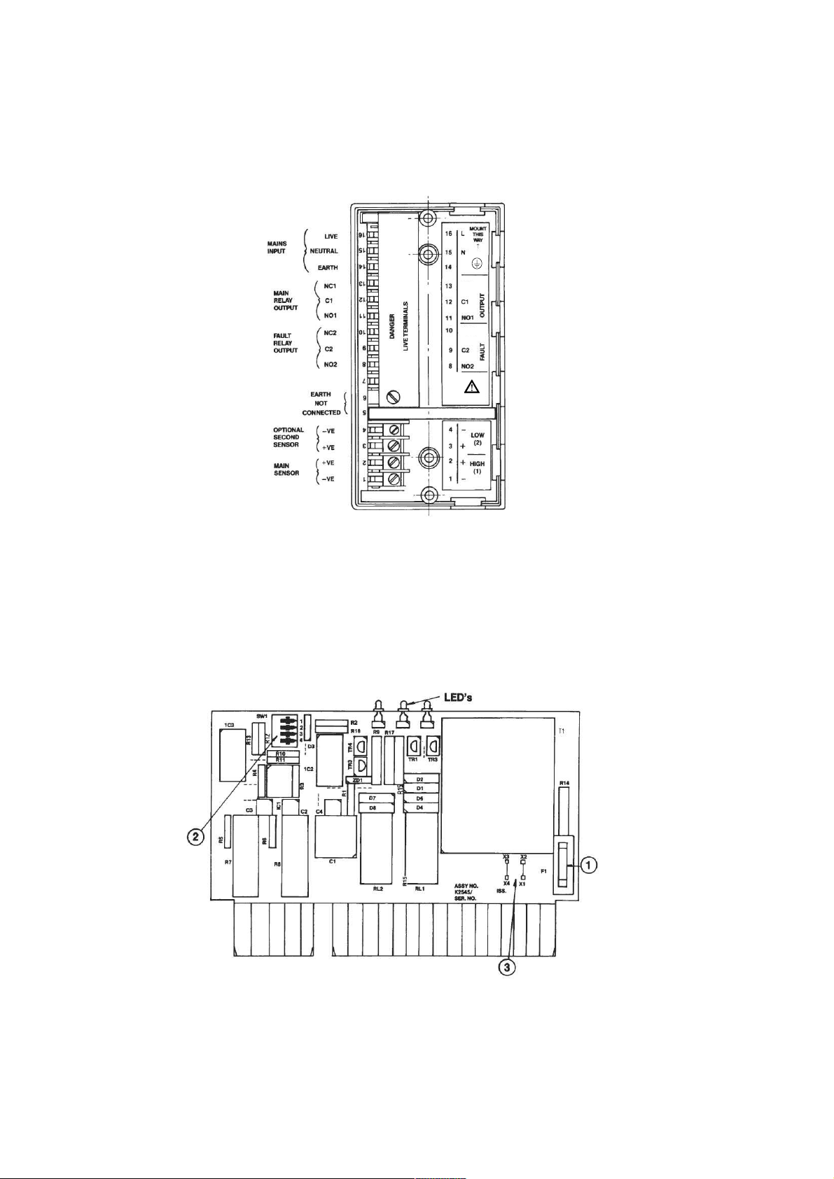
3.2 Terminal arrangements
Figure 1 : MES*L Terminals & Connections
Notes:
• Relay terminals are shown in the de-energised state.
• Terminals 2 & 3 are linked on the MES*L pcb and can use one field cable core if required.
• When two sensors are used with one control unit for a pump control application, the sensor on terminals 1 & 2 must be the
top sensor, and the lower liquid level sensor must be attached to terminals 3 & 4. See section 3.4 “Switch setting
adjustments” .
3.3 Printed Circuit Board Layout
Figure 2
Item 1 : Fuse type 5 x 20mm 500mA quick acting (F) HBC (1500A) IEC60 127
Item 2 : Set of switches to define the operation of the control unit – see below.
Item 3 : Voltage selection links for AC supply. (Factory set)
For 110/120V : X1-X2 & X3-X4
For 220/240V : X2-X3 only.
PROTECTIVE
NC1
NC2
Page 4
Page 4
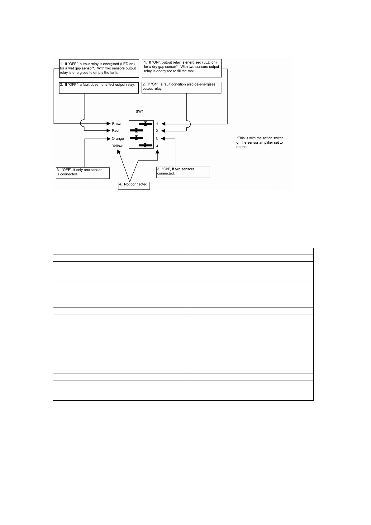
3.4 Switch Setting Adjustment
Access to switches is achieved by removing control unit from base, unclipping plastic panel from rear of control unit
and sliding PCB from housing. After setting switches, reassemble by reversing the disassembly procedure.
Figure 3 :
There is one set of four switches on the pcb of the MES*L unit, which is labelled SW1. This has four colour coded switches
which can be off to the left (in the diagram above) towards the word OFF on the switch itself, or ON to the right, in the direction
of the arrow towards the numbers 1, 2, 3 and 4.
4.0 Technical Specifications
Main relay output 5 amp SPCO resistive 250V a.c.
Fault relay 5 amp SPCO resistive 250V a.c.
Power supply 110/120v a.c. ± 10%
220/240v a.c. ± 10%
50/60 Hz
Temperature range -20°C to + 65°C
Housing IP20 enclosure designed for wall mounting
with 2 screws. Optional DIN rail adaptor
available
Dimensions : mm H = 150 x W = 75 x D = 112
Mounting holes 2 x 3mm Ø on C/L 100mm apart
Sensor power (for 1 or 2 separate Mobrey
Electrosensor)
12v DC nominal
Intrinsically safe
ATEX II (1) G [EEx ia] IIC
LED Indicators 1 (Green) main relay on
2 (Yellow) main relay off
3 (Yellow) fault relay off
NOTE: Fault relay is energised in normal state,
de-energised or off in the fault condition
Max. cable resistance each core 100 ohms
Weight 600 grams
Maximum altitude 2000 m
Maximum humidity 95%
Page 5
Page 5
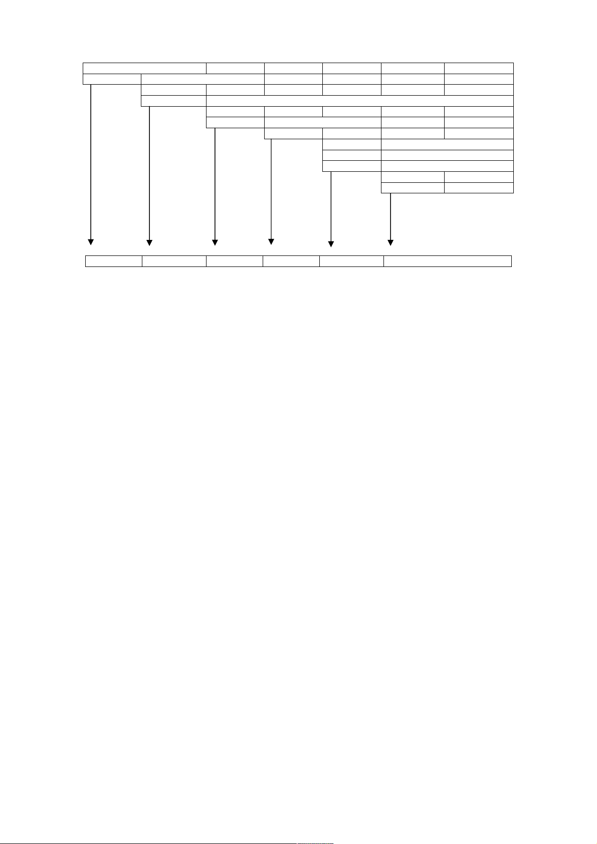
5.0. Model Identification
Production description
MES Mobrey electrosensor
Code Approvals
3 ATEX approved unit for direct connection to intrinsically safe sensors
Code Mounting
L Wall mounting
/
Code Voltage requirements
1 220/240V ac, 50/60 Hz
2 110/120V ac, 50/60 Hz
Code Output relay
S SPCO
MES 3 L / 1 S
6.0. Maintenance / Inspection
This is limited to periodic inspection by a qualified person to ensure that the installation including wiring and equipment housing
is safe.
Clean only with a damp cloth, ensuring that no moisture enters control unit.
Check unit for damage and if damaged do not use.
Page 6

Page 6
Page 7

Page 7
Page 8

Level
Instruction Leaflet
IP242
June 2005
Mobrey Measurement
158 Edinburgh Avenue,
Slough, Berks, UK, SL1 4UE
T +44 (0) 1753 756600
F +44 (0) 1753 823589
mobrey.sales@EmersonProcess.com
www.mobrey.com
Mobrey SA-NV Belgium tel: 02/465 3879
Mobrey GmbH Deutschland tel: 0211/99 808-0
Mobrey SA France tel: 01 30 17 40 80
Mobrey sp z o o Polska tel: 022 871 7865
Mobrey AB Sverige tel: 08-725 01 00
© 2005, Mobrey. The right is reserved to amend details given in this publication without notice.
ABCDEF
 Loading...