

Page 1

MITX-430/MITX-440-DVI-2E
Installation and Use Guide
P/N: 6806800K37B
August 2010
Embedded Computing for
Business-Critical Continuity
TM
Page 2

©
2010 Emerson
All rights reserved.
Trademarks
Emerson, Business-Critical Continuity, Emerson Network Power and the Emerson Network Power logo are trademarks and service
marks of Emerson Electric Co.
owners.
®
Intel
is a trademark or registered trademark of Intel Corporation or its subsidiaries in the United States and other countries.
™
and all other Java-based marks are trademarks or registered trademarks of Sun Microsystems, Inc. in the U.S. and other
Java
countries.
Microsoft
Microsoft Corporation.
PICMG
Industrial Computer Manufacturers Group.
UNIX
®
, Windows® and Windows Me® are registered trademarks of Microsoft Corporation; and Windows XP™ is a trademark of
®
, CompactPCI®, AdvancedTCA™ and the PICMG, CompactPCI and AdvancedTCA logos are registered trademarks of the PCI
®
is a registered trademark of The Open Group in the United States and other countries.
©
2010 Emerson Electric Co. All other product or service names are the property of their respective
Notice
While reasonable efforts have been made to assure the accuracy of this document, Emerson assumes no liability resulting from any
omissions in this document, or from the use of the information obtained therein. Emerson reserves the right to revise this document
and to make changes from time to time in the content hereof without obligation of Emerson to notify any person of such revision or
changes.
Electronic versions of this material may be read online, downloaded for personal use, or referenced in another document as a URL to
a Emerson website. The text itself may not be published commercially in print or electronic form, edited, translated, or otherwise
altered without the permission of Emerson,
It is possible that this publication may contain reference to or information about Emerson products (machines and programs),
programming, or services that are not available in your country. Such references or information must not be construed to mean that
Emerson intends to announce such Emerson products, programming, or services in your country.
Limited and Restricted Rights Legend
If the documentation contained herein is supplied, directly or indirectly, to the U.S. Government, the following notice shall apply
unless otherwise agreed to in writing by Emerson.
Use, duplication, or disclosure by the Government is subject to restrictions as set forth in subparagraph (b)(3) of the Rights in
Technical Data clause at DFARS 252.227-7013 (Nov. 1995) and of the Rights in Noncommercial Computer Software and
Documentation clause at DFARS 252.227-7014 (Jun. 1995).
Contact Address
Emerson Network Power - Embedded Computing
Lilienthalstr. 15
85579 Neubiberg/Munich
Germany
Page 3

Contents
Contents
About this Manual . . . . . . . . . . . . . . . . . . . . . . . . . . . . . . . . . . . . . . . . . . . . . . . . . . . . . . . . . . . . . . . . . . . . . . . 13
1 Introduction . . . . . . . . . . . . . . . . . . . . . . . . . . . . . . . . . . . . . . . . . . . . . . . . . . . . . . . . . . . . . . . . . . . . . . . . . 21
1.1 Features . . . . . . . . . . . . . . . . . . . . . . . . . . . . . . . . . . . . . . . . . . . . . . . . . . . . . . . . . . . . . . . . . . . . . . . . . . . 21
1.1.1 MITX-430 . . . . . . . . . . . . . . . . . . . . . . . . . . . . . . . . . . . . . . . . . . . . . . . . . . . . . . . . . . . . . . . . . . . 21
1.1.2 MITX-440-DVI-2E . . . . . . . . . . . . . . . . . . . . . . . . . . . . . . . . . . . . . . . . . . . . . . . . . . . . . . . . . . . . 23
1.2 Standard Compliances . . . . . . . . . . . . . . . . . . . . . . . . . . . . . . . . . . . . . . . . . . . . . . . . . . . . . . . . . . . . . . 25
1.3 Mechanical Data . . . . . . . . . . . . . . . . . . . . . . . . . . . . . . . . . . . . . . . . . . . . . . . . . . . . . . . . . . . . . . . . . . . 27
1.4 Ordering Information . . . . . . . . . . . . . . . . . . . . . . . . . . . . . . . . . . . . . . . . . . . . . . . . . . . . . . . . . . . . . . . 27
1.4.1 Supported Board Models. . . . . . . . . . . . . . . . . . . . . . . . . . . . . . . . . . . . . . . . . . . . . . . . . . . . . . 27
1.4.2 Board Accessories . . . . . . . . . . . . . . . . . . . . . . . . . . . . . . . . . . . . . . . . . . . . . . . . . . . . . . . . . . . . 27
1.5 Product Identification . . . . . . . . . . . . . . . . . . . . . . . . . . . . . . . . . . . . . . . . . . . . . . . . . . . . . . . . . . . . . . . 28
2 Hardware Preparation and Installation . . . . . . . . . . . . . . . . . . . . . . . . . . . . . . . . . . . . . . . . . . . . . . . . . 31
2.1 Environmental and Power Requirements . . . . . . . . . . . . . . . . . . . . . . . . . . . . . . . . . . . . . . . . . . . . . . 31
2.1.1 Environmental Requirements. . . . . . . . . . . . . . . . . . . . . . . . . . . . . . . . . . . . . . . . . . . . . . . . . . 31
2.1.2 Thermal Requirements . . . . . . . . . . . . . . . . . . . . . . . . . . . . . . . . . . . . . . . . . . . . . . . . . . . . . . . 32
2.1.3 Power Requirements (Single Core Processor Board) . . . . . . . . . . . . . . . . . . . . . . . . . . . . . . 33
2.1.3.1 Full Loading Running Burn-in Test . . . . . . . . . . . . . . . . . . . . . . . . . . . . . . . . . . . . . 33
2.1.3.2 Idle Mode Power Consumption . . . . . . . . . . . . . . . . . . . . . . . . . . . . . . . . . . . . . . . 34
2.1.3.3 Standby Mode Power Consumption . . . . . . . . . . . . . . . . . . . . . . . . . . . . . . . . . . . 35
2.1.4 Power Requirements (Dual Core Processor Board). . . . . . . . . . . . . . . . . . . . . . . . . . . . . . . . 35
2.1.4.1 Full Loading Running Burn-in Test . . . . . . . . . . . . . . . . . . . . . . . . . . . . . . . . . . . . . 36
2.1.4.2 Idle Mode Power Consumption . . . . . . . . . . . . . . . . . . . . . . . . . . . . . . . . . . . . . . . 36
2.1.4.3 Standby Mode Power Consumption . . . . . . . . . . . . . . . . . . . . . . . . . . . . . . . . . . . 37
2.2 Board Thermal Management and Placement . . . . . . . . . . . . . . . . . . . . . . . . . . . . . . . . . . . . . . . . . . . 37
2.2.1 Board Thermal Management . . . . . . . . . . . . . . . . . . . . . . . . . . . . . . . . . . . . . . . . . . . . . . . . . . 37
2.3 Unpacking and Inspecting the Board . . . . . . . . . . . . . . . . . . . . . . . . . . . . . . . . . . . . . . . . . . . . . . . . . . 39
2.4 Preparing the Installation Environment . . . . . . . . . . . . . . . . . . . . . . . . . . . . . . . . . . . . . . . . . . . . . . . . 40
2.5 Processor Cooler Installation and Removal . . . . . . . . . . . . . . . . . . . . . . . . . . . . . . . . . . . . . . . . . . . . . 41
2.6 Memory Module Installation and Removal . . . . . . . . . . . . . . . . . . . . . . . . . . . . . . . . . . . . . . . . . . . . . 42
3 Controls, LEDs, and Connectors . . . . . . . . . . . . . . . . . . . . . . . . . . . . . . . . . . . . . . . . . . . . . . . . . . . . . . . . 45
3.1 Board Layout . . . . . . . . . . . . . . . . . . . . . . . . . . . . . . . . . . . . . . . . . . . . . . . . . . . . . . . . . . . . . . . . . . . . . . . 45
MITX-430/MITX-440-DVI-2E Installation and Use Guide (6806800K37B)
3
Page 4

Contents
Contents
Contents
3.2 Connectors . . . . . . . . . . . . . . . . . . . . . . . . . . . . . . . . . . . . . . . . . . . . . . . . . . . . . . . . . . . . . . . . . . . . . . . . 47
3.2.1 Clear CMOS (P3) . . . . . . . . . . . . . . . . . . . . . . . . . . . . . . . . . . . . . . . . . . . . . . . . . . . . . . . . . . . . . 47
3.2.2 LVDS Header (J5). . . . . . . . . . . . . . . . . . . . . . . . . . . . . . . . . . . . . . . . . . . . . . . . . . . . . . . . . . . . . 47
3.2.3 LVDS Backlight Header (P23) . . . . . . . . . . . . . . . . . . . . . . . . . . . . . . . . . . . . . . . . . . . . . . . . . . 48
3.2.4 LVDS Power . . . . . . . . . . . . . . . . . . . . . . . . . . . . . . . . . . . . . . . . . . . . . . . . . . . . . . . . . . . . . . . . . 48
3.2.5 MINI IDE Header (J8). . . . . . . . . . . . . . . . . . . . . . . . . . . . . . . . . . . . . . . . . . . . . . . . . . . . . . . . . . 48
3.2.6 USB Flash Header (P10) . . . . . . . . . . . . . . . . . . . . . . . . . . . . . . . . . . . . . . . . . . . . . . . . . . . . . . . 49
3.2.7 USB Header (P12) . . . . . . . . . . . . . . . . . . . . . . . . . . . . . . . . . . . . . . . . . . . . . . . . . . . . . . . . . . . . 50
3.2.8 ELO Touch Screen Header (P6). . . . . . . . . . . . . . . . . . . . . . . . . . . . . . . . . . . . . . . . . . . . . . . . . 50
3.2.9 GPIO Header (P4) . . . . . . . . . . . . . . . . . . . . . . . . . . . . . . . . . . . . . . . . . . . . . . . . . . . . . . . . . . . . 51
3.2.10 COM Header (P9, P27) . . . . . . . . . . . . . . . . . . . . . . . . . . . . . . . . . . . . . . . . . . . . . . . . . . . . . . . . 51
3.2.11 RS-232/422/485 (P18). . . . . . . . . . . . . . . . . . . . . . . . . . . . . . . . . . . . . . . . . . . . . . . . . . . . . . . . 51
3.2.12 Power COM (P8, P26) . . . . . . . . . . . . . . . . . . . . . . . . . . . . . . . . . . . . . . . . . . . . . . . . . . . . . . . . . 52
3.2.13 TPM Header (P2) . . . . . . . . . . . . . . . . . . . . . . . . . . . . . . . . . . . . . . . . . . . . . . . . . . . . . . . . . . . . . 53
3.2.14 LPT Header (P11). . . . . . . . . . . . . . . . . . . . . . . . . . . . . . . . . . . . . . . . . . . . . . . . . . . . . . . . . . . . . 54
3.2.15 Front Panel Header (P15). . . . . . . . . . . . . . . . . . . . . . . . . . . . . . . . . . . . . . . . . . . . . . . . . . . . . . 54
3.2.16 BIOS Program Header (P16) . . . . . . . . . . . . . . . . . . . . . . . . . . . . . . . . . . . . . . . . . . . . . . . . . . . 55
3.2.17 Fan Header (P1, P13) . . . . . . . . . . . . . . . . . . . . . . . . . . . . . . . . . . . . . . . . . . . . . . . . . . . . . . . . . 55
3.2.18 MINI PCIE LED (P14) . . . . . . . . . . . . . . . . . . . . . . . . . . . . . . . . . . . . . . . . . . . . . . . . . . . . . . . . . . 56
3.2.19 Case Open Header (P25) . . . . . . . . . . . . . . . . . . . . . . . . . . . . . . . . . . . . . . . . . . . . . . . . . . . . . . 56
4 Functional Description . . . . . . . . . . . . . . . . . . . . . . . . . . . . . . . . . . . . . . . . . . . . . . . . . . . . . . . . . . . . . . . . 57
4.1 Block Diagram . . . . . . . . . . . . . . . . . . . . . . . . . . . . . . . . . . . . . . . . . . . . . . . . . . . . . . . . . . . . . . . . . . . . . 57
4.2 Pineview-D Processor . . . . . . . . . . . . . . . . . . . . . . . . . . . . . . . . . . . . . . . . . . . . . . . . . . . . . . . . . . . . . . . 58
4.3 SMBus Interface and Devices . . . . . . . . . . . . . . . . . . . . . . . . . . . . . . . . . . . . . . . . . . . . . . . . . . . . . . . . . 58
4.4 System Memory . . . . . . . . . . . . . . . . . . . . . . . . . . . . . . . . . . . . . . . . . . . . . . . . . . . . . . . . . . . . . . . . . . . . 60
4.5 Ethernet Interfaces . . . . . . . . . . . . . . . . . . . . . . . . . . . . . . . . . . . . . . . . . . . . . . . . . . . . . . . . . . . . . . . . . 60
4.6 PCI-E Port . . . . . . . . . . . . . . . . . . . . . . . . . . . . . . . . . . . . . . . . . . . . . . . . . . . . . . . . . . . . . . . . . . . . . . . . . . 60
4.7 USB Interface . . . . . . . . . . . . . . . . . . . . . . . . . . . . . . . . . . . . . . . . . . . . . . . . . . . . . . . . . . . . . . . . . . . . . . 61
4.8 VGA, LVDS, LPC, and Audio Interface . . . . . . . . . . . . . . . . . . . . . . . . . . . . . . . . . . . . . . . . . . . . . . . . . . 62
4.9 DVI Interface . . . . . . . . . . . . . . . . . . . . . . . . . . . . . . . . . . . . . . . . . . . . . . . . . . . . . . . . . . . . . . . . . . . . . . . 63
4.10 BIOS Device . . . . . . . . . . . . . . . . . . . . . . . . . . . . . . . . . . . . . . . . . . . . . . . . . . . . . . . . . . . . . . . . . . . . . . . . 63
4.11 IDE . . . . . . . . . . . . . . . . . . . . . . . . . . . . . . . . . . . . . . . . . . . . . . . . . . . . . . . . . . . . . . . . . . . . . . . . . . . . . . . 63
4.12 GPIO Configuration . . . . . . . . . . . . . . . . . . . . . . . . . . . . . . . . . . . . . . . . . . . . . . . . . . . . . . . . . . . . . . . . . 63
4
4.12.1 User Defined GPIO . . . . . . . . . . . . . . . . . . . . . . . . . . . . . . . . . . . . . . . . . . . . . . . . . . . . . . . . . . . 63
MITX-430/MITX-440-DVI-2E Installation and Use Guide (6806800K37B)
Page 5

Contents
4.12.2 ICH8-M GPIO . . . . . . . . . . . . . . . . . . . . . . . . . . . . . . . . . . . . . . . . . . . . . . . . . . . . . . . . . . . . . . . . 64
4.13 Chipset . . . . . . . . . . . . . . . . . . . . . . . . . . . . . . . . . . . . . . . . . . . . . . . . . . . . . . . . . . . . . . . . . . . . . . . . . . . . 68
4.14 Clock Generator . . . . . . . . . . . . . . . . . . . . . . . . . . . . . . . . . . . . . . . . . . . . . . . . . . . . . . . . . . . . . . . . . . . . 69
4.15 Video . . . . . . . . . . . . . . . . . . . . . . . . . . . . . . . . . . . . . . . . . . . . . . . . . . . . . . . . . . . . . . . . . . . . . . . . . . . . . 69
4.16 Storage . . . . . . . . . . . . . . . . . . . . . . . . . . . . . . . . . . . . . . . . . . . . . . . . . . . . . . . . . . . . . . . . . . . . . . . . . . . 69
4.17 Super I/O . . . . . . . . . . . . . . . . . . . . . . . . . . . . . . . . . . . . . . . . . . . . . . . . . . . . . . . . . . . . . . . . . . . . . . . . . . 70
4.18 HW Monitor . . . . . . . . . . . . . . . . . . . . . . . . . . . . . . . . . . . . . . . . . . . . . . . . . . . . . . . . . . . . . . . . . . . . . . . 70
4.19 SPI Flash . . . . . . . . . . . . . . . . . . . . . . . . . . . . . . . . . . . . . . . . . . . . . . . . . . . . . . . . . . . . . . . . . . . . . . . . . . . 70
4.20 Watchdog Timer . . . . . . . . . . . . . . . . . . . . . . . . . . . . . . . . . . . . . . . . . . . . . . . . . . . . . . . . . . . . . . . . . . . 71
4.21 Debug . . . . . . . . . . . . . . . . . . . . . . . . . . . . . . . . . . . . . . . . . . . . . . . . . . . . . . . . . . . . . . . . . . . . . . . . . . . . 71
4.22 Power Management . . . . . . . . . . . . . . . . . . . . . . . . . . . . . . . . . . . . . . . . . . . . . . . . . . . . . . . . . . . . . . . . 71
4.23 Manageability . . . . . . . . . . . . . . . . . . . . . . . . . . . . . . . . . . . . . . . . . . . . . . . . . . . . . . . . . . . . . . . . . . . . . . 71
4.24 RTC . . . . . . . . . . . . . . . . . . . . . . . . . . . . . . . . . . . . . . . . . . . . . . . . . . . . . . . . . . . . . . . . . . . . . . . . . . . . . . . 71
5 Operation . . . . . . . . . . . . . . . . . . . . . . . . . . . . . . . . . . . . . . . . . . . . . . . . . . . . . . . . . . . . . . . . . . . . . . . . . . . 73
5.1 POST . . . . . . . . . . . . . . . . . . . . . . . . . . . . . . . . . . . . . . . . . . . . . . . . . . . . . . . . . . . . . . . . . . . . . . . . . . . . . . 73
5.2 Boot Process . . . . . . . . . . . . . . . . . . . . . . . . . . . . . . . . . . . . . . . . . . . . . . . . . . . . . . . . . . . . . . . . . . . . . . . 73
5.3 Initiating Setup . . . . . . . . . . . . . . . . . . . . . . . . . . . . . . . . . . . . . . . . . . . . . . . . . . . . . . . . . . . . . . . . . . . . . 73
5.4 Setup Utility . . . . . . . . . . . . . . . . . . . . . . . . . . . . . . . . . . . . . . . . . . . . . . . . . . . . . . . . . . . . . . . . . . . . . . . 74
5.4.1 Main Menu . . . . . . . . . . . . . . . . . . . . . . . . . . . . . . . . . . . . . . . . . . . . . . . . . . . . . . . . . . . . . . . . . . 74
5.4.2 Advanced Menu . . . . . . . . . . . . . . . . . . . . . . . . . . . . . . . . . . . . . . . . . . . . . . . . . . . . . . . . . . . . . 75
5.4.3 Chipset Menu. . . . . . . . . . . . . . . . . . . . . . . . . . . . . . . . . . . . . . . . . . . . . . . . . . . . . . . . . . . . . . . . 89
5.4.4 Boot Menu . . . . . . . . . . . . . . . . . . . . . . . . . . . . . . . . . . . . . . . . . . . . . . . . . . . . . . . . . . . . . . . . . . 90
5.4.5 Security Menu . . . . . . . . . . . . . . . . . . . . . . . . . . . . . . . . . . . . . . . . . . . . . . . . . . . . . . . . . . . . . . . 91
5.4.6 Save & Exit Menu. . . . . . . . . . . . . . . . . . . . . . . . . . . . . . . . . . . . . . . . . . . . . . . . . . . . . . . . . . . . . 91
5.5 POST Codes . . . . . . . . . . . . . . . . . . . . . . . . . . . . . . . . . . . . . . . . . . . . . . . . . . . . . . . . . . . . . . . . . . . . . . . . 92
5.5.1 Status Code Ranges . . . . . . . . . . . . . . . . . . . . . . . . . . . . . . . . . . . . . . . . . . . . . . . . . . . . . . . . . . 92
5.5.2 Standard Status Codes. . . . . . . . . . . . . . . . . . . . . . . . . . . . . . . . . . . . . . . . . . . . . . . . . . . . . . . . 93
5.5.2.1 SEC Status Codes . . . . . . . . . . . . . . . . . . . . . . . . . . . . . . . . . . . . . . . . . . . . . . . . . . . 93
5.5.2.2 PEI Status Codes . . . . . . . . . . . . . . . . . . . . . . . . . . . . . . . . . . . . . . . . . . . . . . . . . . . . 94
5.5.2.3 PEI Beep Codes . . . . . . . . . . . . . . . . . . . . . . . . . . . . . . . . . . . . . . . . . . . . . . . . . . . . . 97
5.5.2.4 DXE Status Codes . . . . . . . . . . . . . . . . . . . . . . . . . . . . . . . . . . . . . . . . . . . . . . . . . . . 98
5.5.2.5 DXE Beep Codes . . . . . . . . . . . . . . . . . . . . . . . . . . . . . . . . . . . . . . . . . . . . . . . . . . . 101
5.5.2.6 CPU Exception Status Codes . . . . . . . . . . . . . . . . . . . . . . . . . . . . . . . . . . . . . . . . . 101
5.5.2.7 ASL Status Codes . . . . . . . . . . . . . . . . . . . . . . . . . . . . . . . . . . . . . . . . . . . . . . . . . . 102
MITX-430/MITX-440-DVI-2E Installation and Use Guide (6806800K37B)
5
Page 6

Contents
Contents
Contents
5.5.2.8 OEM-Reserved Status Code Ranges . . . . . . . . . . . . . . . . . . . . . . . . . . . . . . . . . . 103
6 Operating System and Driver Support . . . . . . . . . . . . . . . . . . . . . . . . . . . . . . . . . . . . . . . . . . . . . . . . . 105
6.1 Supported Operating System . . . . . . . . . . . . . . . . . . . . . . . . . . . . . . . . . . . . . . . . . . . . . . . . . . . . . . . 105
6.2 Supported Drivers . . . . . . . . . . . . . . . . . . . . . . . . . . . . . . . . . . . . . . . . . . . . . . . . . . . . . . . . . . . . . . . . . 105
A Related Documentation . . . . . . . . . . . . . . . . . . . . . . . . . . . . . . . . . . . . . . . . . . . . . . . . . . . . . . . . . . . . . . 107
A.1 Emerson Embedded Communications Computing Documents . . . . . . . . . . . . . . . . . . . . . . . . . . 107
A.2 Related Specifications . . . . . . . . . . . . . . . . . . . . . . . . . . . . . . . . . . . . . . . . . . . . . . . . . . . . . . . . . . . . . . 107
Safety Notes . . . . . . . . . . . . . . . . . . . . . . . . . . . . . . . . . . . . . . . . . . . . . . . . . . . . . . . . . . . . . . . . . . . . . . . . . . . . 109
Sicherheitshinweise . . . . . . . . . . . . . . . . . . . . . . . . . . . . . . . . . . . . . . . . . . . . . . . . . . . . . . . . . . . . . . . . . . . . . 133
Index . . . . . . . . . . . . . . . . . . . . . . . . . . . . . . . . . . . . . . . . . . . . . . . . . . . . . . . . . . . . . . . . . . . . . . . . . . . . . . . . . . 157
6
MITX-430/MITX-440-DVI-2E Installation and Use Guide (6806800K37B)
Page 7

List of Tables
Table 1-1 Single Core Processor Board Features . . . . . . . . . . . . . . . . . . . . . . . . . . . . . . . . . . . . . . . . . . 21
Table 1-2 Dual Core Processor Board Features . . . . . . . . . . . . . . . . . . . . . . . . . . . . . . . . . . . . . . . . . . . 23
Table 1-3 Standard Compliances . . . . . . . . . . . . . . . . . . . . . . . . . . . . . . . . . . . . . . . . . . . . . . . . . . . . . . . 25
Table 1-4 Mechanical Data . . . . . . . . . . . . . . . . . . . . . . . . . . . . . . . . . . . . . . . . . . . . . . . . . . . . . . . . . . . . 27
Table 1-5 Available Board Variants . . . . . . . . . . . . . . . . . . . . . . . . . . . . . . . . . . . . . . . . . . . . . . . . . . . . . 27
Table 1-6 Available Board Accessories . . . . . . . . . . . . . . . . . . . . . . . . . . . . . . . . . . . . . . . . . . . . . . . . . . 27
Table 2-1 Environmental Requirements . . . . . . . . . . . . . . . . . . . . . . . . . . . . . . . . . . . . . . . . . . . . . . . . . 31
Table 2-2 Critical Temperature Spots . . . . . . . . . . . . . . . . . . . . . . . . . . . . . . . . . . . . . . . . . . . . . . . . . . . 32
Table 3-1 Clear CMOS . . . . . . . . . . . . . . . . . . . . . . . . . . . . . . . . . . . . . . . . . . . . . . . . . . . . . . . . . . . . . . . . 47
Table 3-2 LVDS Header Pin Definition . . . . . . . . . . . . . . . . . . . . . . . . . . . . . . . . . . . . . . . . . . . . . . . . . . . 47
Table 3-3 LVDS Backlight Header PIn Definition . . . . . . . . . . . . . . . . . . . . . . . . . . . . . . . . . . . . . . . . . . 48
Table 3-4 LVDS Power . . . . . . . . . . . . . . . . . . . . . . . . . . . . . . . . . . . . . . . . . . . . . . . . . . . . . . . . . . . . . . . . 48
Table 3-5 MINI IDE Header PIN Definition . . . . . . . . . . . . . . . . . . . . . . . . . . . . . . . . . . . . . . . . . . . . . . . 48
Table 3-6 USB Flash Header Pin Definition . . . . . . . . . . . . . . . . . . . . . . . . . . . . . . . . . . . . . . . . . . . . . . . 49
Table 3-7 USB Header Pin Definition . . . . . . . . . . . . . . . . . . . . . . . . . . . . . . . . . . . . . . . . . . . . . . . . . . . . 50
Table 3-8 ELO Touch Screen Header Pin Definition . . . . . . . . . . . . . . . . . . . . . . . . . . . . . . . . . . . . . . . 50
Table 3-9 GPIO Header Pin Definition . . . . . . . . . . . . . . . . . . . . . . . . . . . . . . . . . . . . . . . . . . . . . . . . . . . 51
Table 3-10 COM3, COM6 Header Pin Definition . . . . . . . . . . . . . . . . . . . . . . . . . . . . . . . . . . . . . . . . . . . 51
Table 3-11 RS-232/422/485 Header Pin Definition . . . . . . . . . . . . . . . . . . . . . . . . . . . . . . . . . . . . . . . . 51
Table 3-12 RS-232/422/485 Jumper Selection (P28) . . . . . . . . . . . . . . . . . . . . . . . . . . . . . . . . . . . . . . . 52
Table 3-13 COM4, COM5 Header Pin Definition . . . . . . . . . . . . . . . . . . . . . . . . . . . . . . . . . . . . . . . . . . . 52
Table 3-14 COM4, COM5 Pin9 Selection . . . . . . . . . . . . . . . . . . . . . . . . . . . . . . . . . . . . . . . . . . . . . . . . . 52
Table 3-15 TPM Header Pin Definition . . . . . . . . . . . . . . . . . . . . . . . . . . . . . . . . . . . . . . . . . . . . . . . . . . . 53
Table 3-16 LPT Header Pin Definition . . . . . . . . . . . . . . . . . . . . . . . . . . . . . . . . . . . . . . . . . . . . . . . . . . . . 54
Table 3-17 Front Panel Header Pin Definition . . . . . . . . . . . . . . . . . . . . . . . . . . . . . . . . . . . . . . . . . . . . . 54
Table 3-18 BIOS Program Header Pin Definition . . . . . . . . . . . . . . . . . . . . . . . . . . . . . . . . . . . . . . . . . . . 55
Table 3-19 Smart Fan Header Pin Definition . . . . . . . . . . . . . . . . . . . . . . . . . . . . . . . . . . . . . . . . . . . . . . 55
Table 3-20 MINI PCIE Wireless LAN LED Header Pin Definition . . . . . . . . . . . . . . . . . . . . . . . . . . . . . . . 56
Table 3-21 Case Open Header Pin Definition . . . . . . . . . . . . . . . . . . . . . . . . . . . . . . . . . . . . . . . . . . . . . . 56
Table 4-1 I2C Device Address . . . . . . . . . . . . . . . . . . . . . . . . . . . . . . . . . . . . . . . . . . . . . . . . . . . . . . . . . . 60
Table 4-2 PCI-E Port . . . . . . . . . . . . . . . . . . . . . . . . . . . . . . . . . . . . . . . . . . . . . . . . . . . . . . . . . . . . . . . . . . 60
Table 4-3 ICH8-M GPIO Definition . . . . . . . . . . . . . . . . . . . . . . . . . . . . . . . . . . . . . . . . . . . . . . . . . . . . . . 64
Table 5-1 Setup Utility . . . . . . . . . . . . . . . . . . . . . . . . . . . . . . . . . . . . . . . . . . . . . . . . . . . . . . . . . . . . . . . . 74
Table 5-2 Main Menu . . . . . . . . . . . . . . . . . . . . . . . . . . . . . . . . . . . . . . . . . . . . . . . . . . . . . . . . . . . . . . . . . 74
Table 5-3 Legacy OPROM Support . . . . . . . . . . . . . . . . . . . . . . . . . . . . . . . . . . . . . . . . . . . . . . . . . . . . . 75
Table 5-4 Advanced Menu . . . . . . . . . . . . . . . . . . . . . . . . . . . . . . . . . . . . . . . . . . . . . . . . . . . . . . . . . . . . 75
MITX-430/MITX-440-DVI-2E Installation and Use Guide (6806800K37B)
7
Page 8

List of Tables
Table 5-5 ACPI Settings . . . . . . . . . . . . . . . . . . . . . . . . . . . . . . . . . . . . . . . . . . . . . . . . . . . . . . . . . . . . . . . 76
Table 5-6 Trusted Computing . . . . . . . . . . . . . . . . . . . . . . . . . . . . . . . . . . . . . . . . . . . . . . . . . . . . . . . . . . 76
Table 5-7 S5 RTC Wake Setting . . . . . . . . . . . . . . . . . . . . . . . . . . . . . . . . . . . . . . . . . . . . . . . . . . . . . . . . . 77
Table 5-8 CPU Configuration . . . . . . . . . . . . . . . . . . . . . . . . . . . . . . . . . . . . . . . . . . . . . . . . . . . . . . . . . . 77
Table 5-9 IDE Configuration . . . . . . . . . . . . . . . . . . . . . . . . . . . . . . . . . . . . . . . . . . . . . . . . . . . . . . . . . . . 78
Table 5-10 IGD-LCD Control . . . . . . . . . . . . . . . . . . . . . . . . . . . . . . . . . . . . . . . . . . . . . . . . . . . . . . . . . . . . 79
Table 5-11 USB Configuration . . . . . . . . . . . . . . . . . . . . . . . . . . . . . . . . . . . . . . . . . . . . . . . . . . . . . . . . . . . 80
Table 5-12 EMC2103 H/W Monitor . . . . . . . . . . . . . . . . . . . . . . . . . . . . . . . . . . . . . . . . . . . . . . . . . . . . . . 81
Table 5-13 Super IO Configuration . . . . . . . . . . . . . . . . . . . . . . . . . . . . . . . . . . . . . . . . . . . . . . . . . . . . . . 81
Table 5-14 Serial Port 1 Configuration . . . . . . . . . . . . . . . . . . . . . . . . . . . . . . . . . . . . . . . . . . . . . . . . . . . 82
Table 5-15 Serial Port 2 Configuration . . . . . . . . . . . . . . . . . . . . . . . . . . . . . . . . . . . . . . . . . . . . . . . . . . . 82
Table 5-16 Serial Port 3 Configuration . . . . . . . . . . . . . . . . . . . . . . . . . . . . . . . . . . . . . . . . . . . . . . . . . . . 83
Table 5-17 Serial Port 4 Configuration . . . . . . . . . . . . . . . . . . . . . . . . . . . . . . . . . . . . . . . . . . . . . . . . . . . 83
Table 5-18 Serial Port 5 Configuration . . . . . . . . . . . . . . . . . . . . . . . . . . . . . . . . . . . . . . . . . . . . . . . . . . . 84
Table 5-19 Serial Port 6 Configuration . . . . . . . . . . . . . . . . . . . . . . . . . . . . . . . . . . . . . . . . . . . . . . . . . . . 84
Table 5-20 Parallel Port Configuration . . . . . . . . . . . . . . . . . . . . . . . . . . . . . . . . . . . . . . . . . . . . . . . . . . . 85
Table 5-21 Watchdog Timer Configuration . . . . . . . . . . . . . . . . . . . . . . . . . . . . . . . . . . . . . . . . . . . . . . . 85
Table 5-22 W83627UHG H/W Monitor . . . . . . . . . . . . . . . . . . . . . . . . . . . . . . . . . . . . . . . . . . . . . . . . . . . 86
Table 5-23 Serial Port Console Redirection . . . . . . . . . . . . . . . . . . . . . . . . . . . . . . . . . . . . . . . . . . . . . . . 86
Table 5-24 COM1 and COM2 Console Redirection Settings . . . . . . . . . . . . . . . . . . . . . . . . . . . . . . . . . 87
Table 5-25 Chipset Menu . . . . . . . . . . . . . . . . . . . . . . . . . . . . . . . . . . . . . . . . . . . . . . . . . . . . . . . . . . . . . . . 89
Table 5-26 Host Bridge . . . . . . . . . . . . . . . . . . . . . . . . . . . . . . . . . . . . . . . . . . . . . . . . . . . . . . . . . . . . . . . . . 89
Table 5-27 South Bridge . . . . . . . . . . . . . . . . . . . . . . . . . . . . . . . . . . . . . . . . . . . . . . . . . . . . . . . . . . . . . . . 89
Table 5-28 Boot Menu . . . . . . . . . . . . . . . . . . . . . . . . . . . . . . . . . . . . . . . . . . . . . . . . . . . . . . . . . . . . . . . . . 90
Table 5-29 Security Menu . . . . . . . . . . . . . . . . . . . . . . . . . . . . . . . . . . . . . . . . . . . . . . . . . . . . . . . . . . . . . . 91
Table 5-30 Save & Exit Menu . . . . . . . . . . . . . . . . . . . . . . . . . . . . . . . . . . . . . . . . . . . . . . . . . . . . . . . . . . . . 91
Table 5-31 Status Code Ranges . . . . . . . . . . . . . . . . . . . . . . . . . . . . . . . . . . . . . . . . . . . . . . . . . . . . . . . . . 92
Table 5-32 SEC Status Codes . . . . . . . . . . . . . . . . . . . . . . . . . . . . . . . . . . . . . . . . . . . . . . . . . . . . . . . . . . . . 93
Table 5-33 PEI Status Codes . . . . . . . . . . . . . . . . . . . . . . . . . . . . . . . . . . . . . . . . . . . . . . . . . . . . . . . . . . . . 94
Table 5-34 PEI Beep Codes . . . . . . . . . . . . . . . . . . . . . . . . . . . . . . . . . . . . . . . . . . . . . . . . . . . . . . . . . . . . . 97
Table 5-35 DXE Status Codes . . . . . . . . . . . . . . . . . . . . . . . . . . . . . . . . . . . . . . . . . . . . . . . . . . . . . . . . . . . 98
Table 5-36 DXE Beep Codes . . . . . . . . . . . . . . . . . . . . . . . . . . . . . . . . . . . . . . . . . . . . . . . . . . . . . . . . . . .101
Table 5-37 CPU Exception Status Codes . . . . . . . . . . . . . . . . . . . . . . . . . . . . . . . . . . . . . . . . . . . . . . . . .101
Table 5-38 ASL Status Codes . . . . . . . . . . . . . . . . . . . . . . . . . . . . . . . . . . . . . . . . . . . . . . . . . . . . . . . . . . . 102
Table 5-39 OEM-Reserved Status Code Ranges . . . . . . . . . . . . . . . . . . . . . . . . . . . . . . . . . . . . . . . . . . . 103
Table 6-1 Supported Drivers . . . . . . . . . . . . . . . . . . . . . . . . . . . . . . . . . . . . . . . . . . . . . . . . . . . . . . . . . .105
8
MITX-430/MITX-440-DVI-2E Installation and Use Guide (6806800K37B)
Page 9

List of Tables
Table A-1 Emerson Network Power - Embedded Computing Publications . . . . . . . . . . . . . . . . . . 107
Table A-2 Related Specifications . . . . . . . . . . . . . . . . . . . . . . . . . . . . . . . . . . . . . . . . . . . . . . . . . . . . . . 107
MITX-430/MITX-440-DVI-2E Installation and Use Guide (6806800K37B)
9
Page 10

List of Tables
10
MITX-430/MITX-440-DVI-2E Installation and Use Guide (6806800K37B)
Page 11

List of Figures
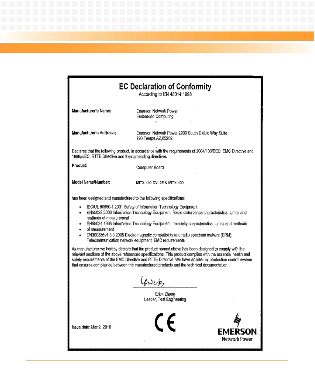
Figure 1-1 Declaration of Conformity . . . . . . . . . . . . . . . . . . . . . . . . . . . . . . . . . . . . . . . . . . . . . . . . 26
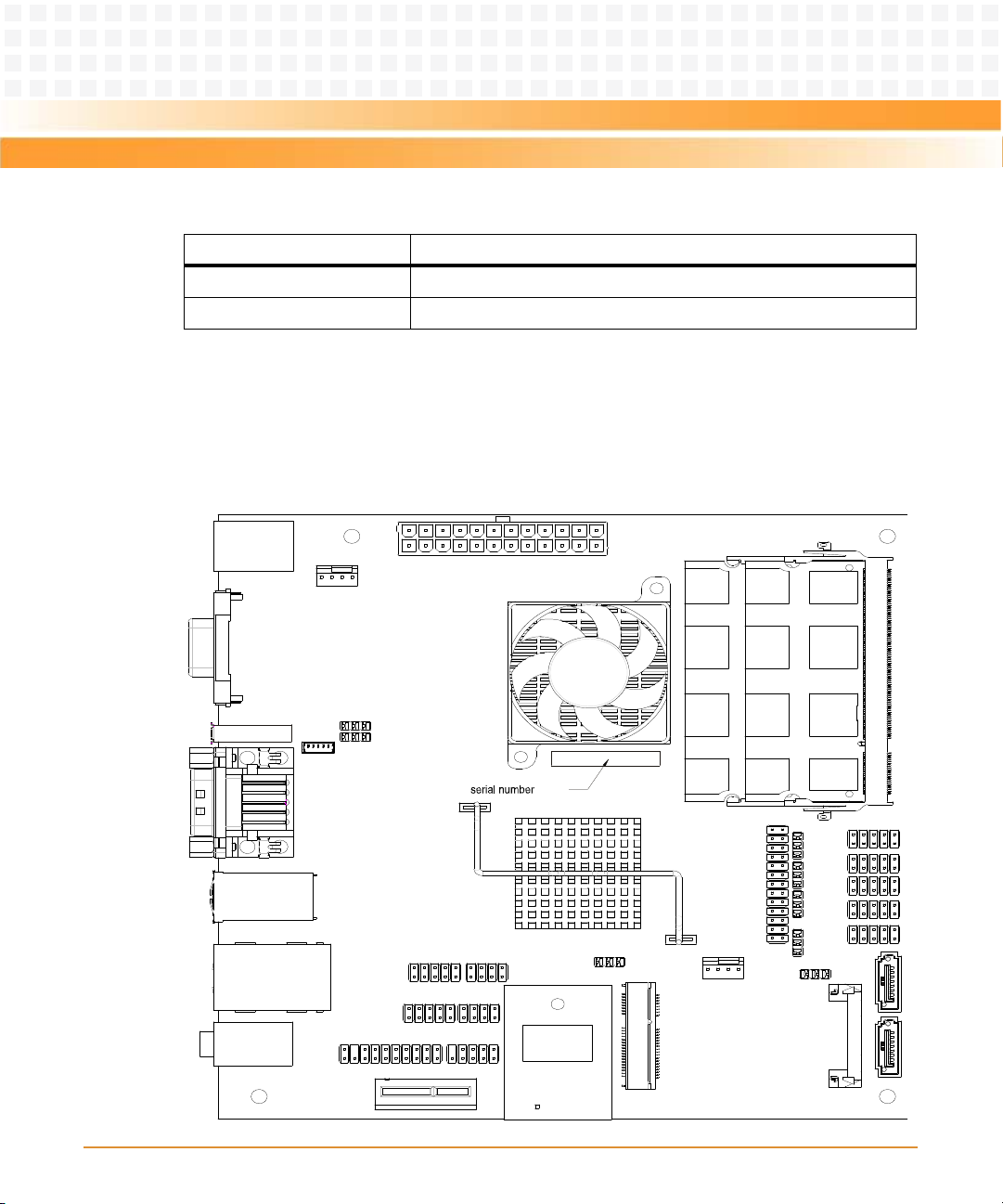
Figure 1-2 Single Core Processor Board - Serial Number Location . . . . . . . . . . . . . . . . . . . . . . . 28
Figure 1-3 Dual Core Processor Board -Serial Number Location . . . . . . . . . . . . . . . . . . . . . . . . . 29
Figure 2-1 Board Thermal Management . . . . . . . . . . . . . . . . . . . . . . . . . . . . . . . . . . . . . . . . . . . . . 38
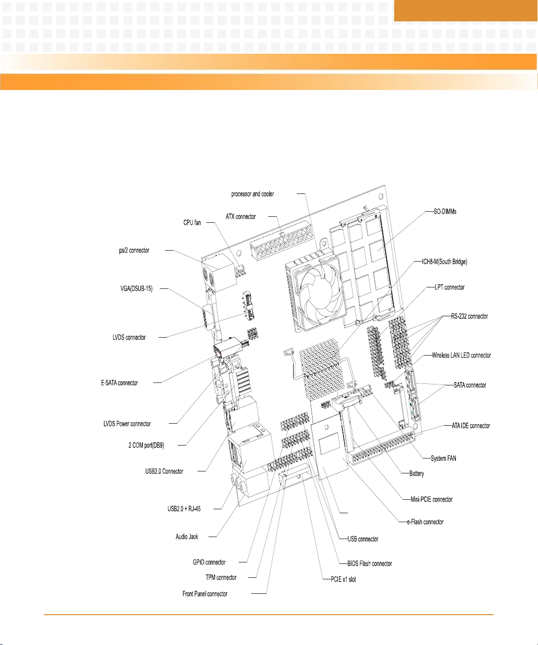
Figure 3-1 Single Core Motherboard Components . . . . . . . . . . . . . . . . . . . . . . . . . . . . . . . . . . . . 45
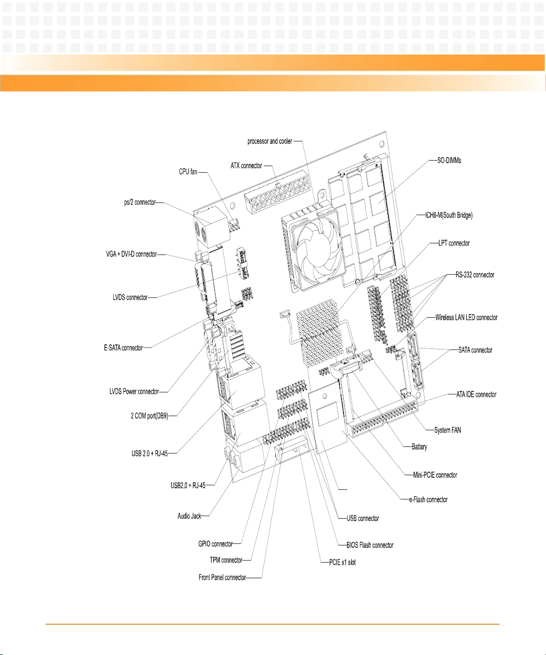
Figure 3-2 Dual Core Motherboard Components . . . . . . . . . . . . . . . . . . . . . . . . . . . . . . . . . . . . . . 46
Figure 4-1 Motherboard Block Diagram . . . . . . . . . . . . . . . . . . . . . . . . . . . . . . . . . . . . . . . . . . . . . 57
Figure 4-2 Board I2C Device Connection . . . . . . . . . . . . . . . . . . . . . . . . . . . . . . . . . . . . . . . . . . . . . 59
Figure 4-3 PCI-E Connection . . . . . . . . . . . . . . . . . . . . . . . . . . . . . . . . . . . . . . . . . . . . . . . . . . . . . . . 61
Figure 4-4 USB Ports Connection . . . . . . . . . . . . . . . . . . . . . . . . . . . . . . . . . . . . . . . . . . . . . . . . . . . 62
MITX-430/MITX-440-DVI-2E Installation and Use Guide (6806800K37B)
11
Page 12

List of Figures
12
MITX-430/MITX-440-DVI-2E Installation and Use Guide (6806800K37B)
Page 13
About this Manual
Overview of Contents
This manual is divided into the following chapters and appendix.
z Chapter 1, Introduction, on page 21, describes the features of single core and dual core
processors, standard compliances, mechanical data, ordering information, and product
identification.
z Chapter 2, Hardware Preparation and Installation, on page 31, describes the environmental
and power requirements, installation prerequisites, processor cooler and memory module
installation and removal procedures.
z Chapter 3, Controls, LEDs, and Connectors, on page 45, describes the LEDs and connectors
used on the motherboard.
z Chapter 4, Functional Description, on page 57, describes the functionalities provided on the
motherboard.
z Chapter 5, Operation, on page 73, describes the boot process, setup utility, and POST
codes.
z Chapter 6, Operating System and Driver Support, on page 105, describes the supported
Operating Systems and Drivers.
z Appendix A, Related Documentation, on page 107, lists the related documents.
Abbreviations
This document uses the following abbreviations:
Abbreviation Definition
ACPI Advanced Configuration and Power Interface
AHCI Advanced Host Controller Interface
AMI American Megatrends Inc
AMT Active Management Technology
AP Application Processor
APIC Advanced Programmable Interrupt Controller
ASL ACPI Source Language
MITX-430/MITX-440-DVI-2E Installation and Use Guide (6806800K37B)
13
Page 14

About this Manual
About this Manual
Abbreviation Definition
ATA Advanced Technology Attachment
ATAPI AT Attachment Packet Interface
ATX Advance Technology Extended
BDS Boot Device Selection
BIOS Basic Input-Output System
BSP Boot Strap Processor
CMOS Complementary Metal Oxide Semiconductor
COM Communications
CRT Cathode Ray Tube
CSM Compatibility Support Module
CTS Clear To Send
DC Dual Core/Direct Current
DCD Data Carrier Detect
DMA Direct Memory Access
DMI Direct Media Interface
DSR Device Status Register
DTR Data Terminal Ready
DVI Digital Visual Interface
DVMT Dynamic Video Memory Technology
DXE Driver Execution Environment
ECC Error Checking and Correcting
ECP Extended Capabilities Parallel Port
EFI Extensible Firmware Interface
EHCI Enhanced Host Controller Interface
EMC Electromagnetic Magnetic Compatibility
EMS Emergency Management Services
EPP Enhanced Parallel Port
ESD Electro-Static Discharge
14
MITX-430/MITX-440-DVI-2E Installation and Use Guide (6806800K37B)
Page 15

About this Manual
Abbreviation Definition
GBE Gigabit Ethernet
GLCI Gigabit LAN Connect Interface
GPI General Purpose Input
GPIO General Purpose Input Output
GPO General Purpose Output
GPU Graphics Processing Unit
IDE Integrated Device Electronics
IGD Internal Graphics Device
IPL Initial Program Loader
LFP Local Flat Panel
LPC Low Pin Count
LPT Line Printer Terminal
LVDS Low Voltage Differential Signaling
MAC Medium Access Control
MSR Mode Specific Register
NMI Non-Maskable Interrupt
NVRAM Non-Volatile RAM
OEM Original Equipment Manufacturer
PATA Parallel AT Attachment
PCB Printed Circuit Board
PCI Peripheral Component Interface
PCIE Peripheral Component Interface Express
PEG PCI Express Graphics
PEI Pre-EFI Initialization
PIC Programmable Interrupt Controller
PIO Programmed Input Output
POST Power on Self Test
PPI PEIM-to-PEIM Interface
MITX-430/MITX-440-DVI-2E Installation and Use Guide (6806800K37B)
15
Page 16

About this Manual
About this Manual
Abbreviation Definition
PWM Pulse Width Modulation
PXE Preboot Execution Environment
RGB Red,Green,Blue
RTC Real Time Clock
RTS Request To Send
RXD Receive X Data
SATA Serial AT Attachment
SC Single Core
SCSI Small Computer System Interface
SIMD Single Instruction Multiple Data
SIO Super Input/Output
SMBus System Management Bus
SMM System Management Mode
SPD Serial Presence Detect
SPI Serial Peripheral Interface
SPP Standard Parallel Port
TACH Tachometer
TDP Thermal Dissipation Power
TPM Trusted Platform Module
TXD Transmit X data
UEFI Unified Extensible Firmware Interface
UHCI Universal Host Controller Interface
VBIOS Video BIOS
VCC Voltage Current Circuit
VCORE Core Voltage
VGA Video Graphics Adapter
16
MITX-430/MITX-440-DVI-2E Installation and Use Guide (6806800K37B)
Page 17
About this Manual
Abbreviation Definition
WDT Watch Dog Timer
WP Write Protect
XD Execute Disable
XDP Extended Debug Port
Conventions
The following table describes the conventions used throughout this manual.
Notation Description
0x00000000 Typical notation for hexadecimal numbers (digits are
0b0000 Same for binary numbers (digits are 0 and 1)
bold Used to emphasize a word
Screen Used for on-screen output and code related elements
Courier + Bold Used to characterize user input and to separate it
0 through F), for example used for addresses and
offsets
or commands in body text
from system output
Reference Used for references and for table and figure
descriptions
File > Exit Notation for selecting a submenu
<text> Notation for variables and keys
[text] Notation for software buttons to click on the screen
and parameter description
... Repeated item for example node 1, node 2, ..., node
12
.
.
.
.. Ranges, for example: 0..4 means one of the integers
Omission of information from example/command
that is not necessary at the time being
0,1,2,3, and 4 (used in registers)
MITX-430/MITX-440-DVI-2E Installation and Use Guide (6806800K37B)
17
Page 18
About this Manual
About this Manual
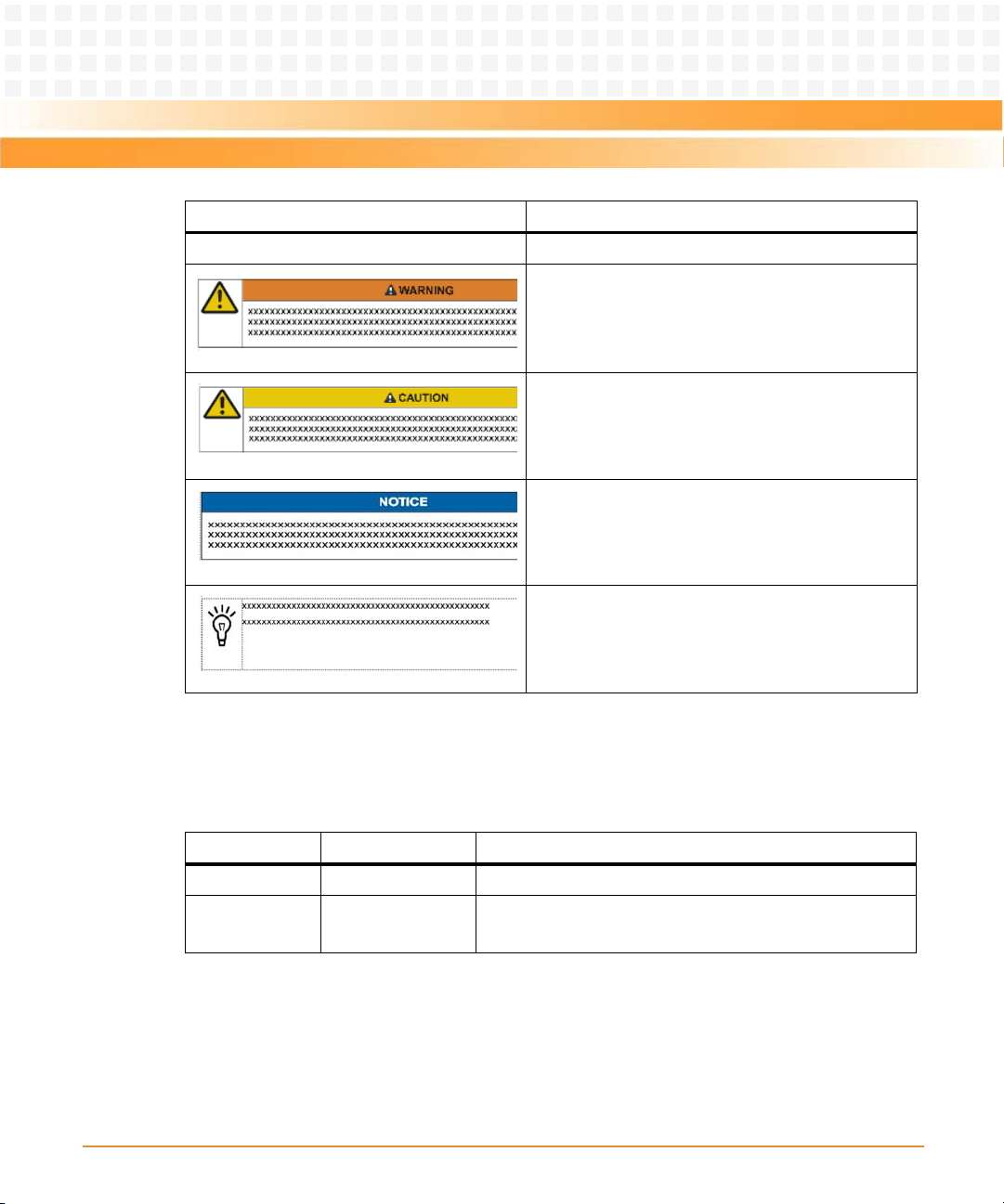
Notation Description
|Logical OR
Indicates a hazardous situation which, if not avoided,
could result in death or serious injury
Indicates a hazardous situation which, if not avoided,
may result in minor or moderate injury
Indicates a property damage message
Summary of Changes
This is the initial version of the manual.
Part Number Publication Date Description
6806800K37A March 2010 GA version
6806800K37B August 2010 Updated the manual with new marketing numbers MITX-
430/MITX-440-DVI-2E.
Comments and Suggestions
We welcome and appreciate your comments on our documentation. We want to know what
you think about our manuals and how we can make them better.
No danger encountered. Pay attention to important
information
18
MITX-430/MITX-440-DVI-2E Installation and Use Guide (6806800K37B)
Page 19

About this Manual
Mail comments to us by filling out the following online form:
http://www.emersonnetworkpowerembeddedcomputing.com/ > Contact Us > Online Form
In "Ar ea of I ntere st" selec t "Tec hni cal Doc ument ati on" . Be sur e to inc lud e th e ti tle, p ar t nu mber,
and revision of the manual and tell us how you used it.
MITX-430/MITX-440-DVI-2E Installation and Use Guide (6806800K37B)
19
Page 20

About this Manual
About this Manual
20
MITX-430/MITX-440-DVI-2E Installation and Use Guide (6806800K37B)
Page 21

Introduction
1.1 Features
The MITX-430 is a Mini-ITX motherboard based on the Intel® Atom™ D410 single-core or
D510 dual-core processor that offers improved processing and graphics performance over
existing Mini-ITX Intel Atom based products.
It is designed to allow easy, cost-effective replacement of the motherboard in a production
environment. There are two versions of MITX-430:
z MITX-430 - Single core processor for low power consumption.
z MITX-440-DVI-2E - Dual core processor with some additional features for higher
performance, which still retains the low power consumption.
MITX-430 uses the latest generation Unified Extensible Firmware Interface (UEFI) Basic Input
Output System (BIOS) from
between the low-level hardware interfaces and the OS level in an efficient manner that
provides superior reliability.
Chapter 1
American Megatrends Inc (AMI). This manages the interaction
The following sections describe some of the key features of MITX-430 single core and MITX440-DVI-2E dual core processors.
1.1.1 MITX-430
The following table lists the features of the single core processor board:
Table 1-1 Single Core Processor Board Features
Function Features
CPU (uFCBGA) z Intel Pineview-D SC Processor (D410)
Chipset Intel ICH8-M
z Frequency: Pineview-D SC 1.66GHz with TDP less than 10W
z Supports up to 4GB DDR2 SO-DIMM
z Supports 667MHz
z Integrated Graphic Process Unit
z 3rd generation graphics core, 400MHz render clock frequency
z Supports one VGA
z Supports one LVDS
MITX-430/MITX-440-DVI-2E Installation and Use Guide (6806800K37B)
21
Page 22

Introduction
Table 1-1 Single Core Processor Board Features (continued)
Function Features
System BIOS feature One piece 4MB SPI boot device
Super I/O W83627UHG-LF
RTC Integrated in ICH8-M
Audio z Audio on board (ALC888-GR-LF)
z Rear: Line-in, Line out, MIC-in
LAN 10/100/1000M Ethernet PHY, Intel WG82567V
USB Supports 10 USB2.0 high speed ports (four rear, five on header, and one mini
PCI-Express)
Expansion slots z One PCI-E x1 slot
z One Mini-PCIE card slot
z One standard USB flash disk (2x5Pin, 2.54mmPitch)
Rear panel ports z One 2xUSB2.0 ports stack one LAN (RJ-45)
z One 2xUSB2.0 stack connector
z One vertical triple stack (MIC-in, Line-in, Line-out)
z One stack PS/2 port
z One e-SATA port
z One VGA DSUB-15
z One stacked dual DSUB-9 serial port
Power connectors 24-pin ATX power connector
Fan Supports two smart fans (4 Pin), one for CPU and one for System
Serial ATA supports one e-SATA and two SATA ports
PATA Supports one Mini-IDE (44Pin)
Hardware monitor Voltage, temperature, and fan speed control
Watchdog Supports 1-255s or 1-255m watchdog
Trusted Pl atform
Module
Power management z ACPI1.0b compatible
COM Port Supports 6 COM ports (two to DSUB-9 in rear I/O region, one
22
Supports one TPM connector (2x10, 2.54mm Pin header)
z Supports ATX power supply
RS-232/422/485 port, two Power COM, and one to 2x5Pin header)
MITX-430/MITX-440-DVI-2E Installation and Use Guide (6806800K37B)
Page 23
Introduction
Table 1-1 Single Core Processor Board Features (continued)
Function Features
LPT Port Supports one parallel port (2x13Pin Header)
Front panel 2x5Pin header, supports power button, reset button, power LED, HDD LED,
GPIO Supports 4 GPI and 4 GPO
Board size z Mini-ITX 170mm x 170mm
1.1.2 MITX-440-DVI-2E
The following table lists the features of the dual core processor board:
Table 1-2 Dual Core Processor Board Features
Function Features
CPU (uFCBGA) z Intel Pineview-D DC Processor (D510)
z Frequency: Pineview-D DC 1.66GHz with TDP less than 13W
z Supports up to 4GB DDR2 SO-DIMM
z Supports 667MHz
z Integrated Graphic Process Unit
z 3rd generation graphics core, 400MHz render clock frequency
z Supports one VGA
z Supports one LVDS
z Supports one DVI (derived from LVDS)
Chipset Intel ICH8-M
and standby LED
z 6 Layers PCB
System BIOS feature One piece 4MB SPI boot device
Super I/O W83627UHG-LF
RTC Integrated in ICH8-M
Audio z Audio on board (ALC888-GR-LF)
z Rear: Line-in, Line out, MIC-in
MITX-430/MITX-440-DVI-2E Installation and Use Guide (6806800K37B)
23
Page 24

Introduction
Table 1-2 Dual Core Processor Board Features (continued)
Function Features
LAN z 10/100/1000M Ethernet PHY, Intel WG82567V
z 10/100/1000M Ethernet Controller, Intel WG82574L
USB Supports 10 USB2.0 high speed ports (four rear, five on header, and one mini
PCI-Express)
Expansion slots z One PCI-E x1 slot
z One Mini-PCIE card slot
z One standard USB flash disk (2x5Pin, 2.54mmPitch)
Rear panel ports z Two 2xUSB2.0 ports stack one LAN (RJ-45)
z One vertical triple stack (MIC-in, Line-in, Line-out)
z One stack PS/2 port
z One e-SATA port
z One VGA DSUB-15 stack DVI port
z One stacked dual DSUB-9 serial port
Power connectors 24-pin ATX power connector
Fan Supports two smart fans (4 Pin), one for CPU and one for the system
Serial ATA supports one e-SATA and two SATA ports
PATA Support one Mini-IDE (44Pin)
Hardware monitor Voltage, temperature, and fan speed control
Watchdog Supports 1-255s or 1-255m watchdog
Trusted Pl atform
Module
Power management z ACPI1.0b compatible
COM Port Supports 6 COM ports (two to DSUB-9 in rear I/O region, one
LPT Port Supports one parallel port (2x13Pin Header)
Front panel 2x5Pin Header, supports power button, reset button, power LED, HDD LED,
GPIO Supports 4 GPI and 4 GPO
24
Supports one TPM connector (2x10, 2.54mm Pin header)
z Supports ATX power supply
RS-232/422/485 port, two power COM, and one to 2x5Pin header)
and standby LED
MITX-430/MITX-440-DVI-2E Installation and Use Guide (6806800K37B)
Page 25
Introduction
Table 1-2 Dual Core Processor Board Features (continued)
Function Features
Board size z Mini-ITX 170mm x 170mm
z 6 Layers PCB
1.2 Standard Compliances
MITX-430/MITX-440-DVI-2E meets the following standards.
Table 1-3 Standard Compliances
Standard Description
IEC 60950-1 General requirements of Safety-Part 1 of Information
EN55024 (EU) Limits and methods of measurements of immunity
FCC 47 CFR Part 15 Subpart B (US), Class B Federal Communications Commission Radio Frequency
EN55022 Class B (EU) Limits and methods of measurements of radio
AS/NZS CISPR 22 Class B (Australia/New
Zealand)
VCCI Class B (Japan) Voluntary Control Council for Interference by
Technology Equipment.
characteristics of Information Technology Equipment.
Devices class B level requirements.
disturbance characteristics of Information Technology
Equipment.
Limits and methods of measurement of radio
disturbance characteristics of Information Technology
Equipment.
Information Technology Equipment.
MITX-430/MITX-440-DVI-2E Installation and Use Guide (6806800K37B)
25
Page 26
Introduction
Figure 1-1 Declaration of Conformity
26
MITX-430/MITX-440-DVI-2E Installation and Use Guide (6806800K37B)
Page 27
Introduction
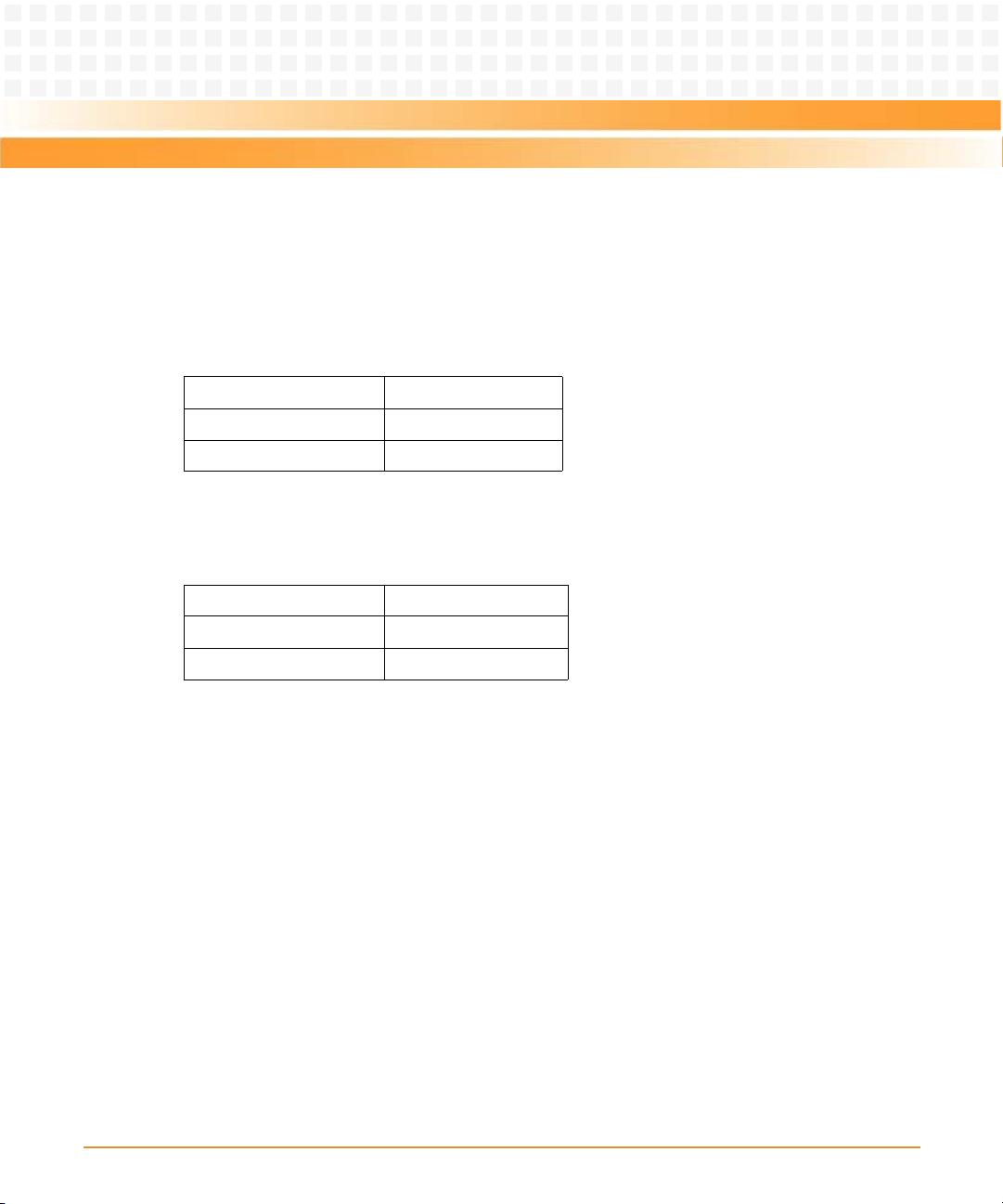
1.3 Mechanical Data
The following table provides details about the dimensions and weight of the board:
Table 1-4 Mechanical Data
Feature Value
Dimensions 170mm x 170mm
Weight Dual core board: 353g
1.4 Ordering Information
When ordering board variants or board accessories, use the order numbers given in the
following sections.
1.4.1 Supported Board Models
The following board models are supported:
Table 1-5 Available Board Variants
Single core board: 325g
Order Number Description
MITX-430 Single-core Intel Atom based Mini-ITX board with standard I/O.
MITX-440-DVI-2E Dual-core Intel Atom based Mini-ITX with standard and optional I/O.
1.4.2 Board Accessories
The following accessories are shipped with the board:
Table 1-6 Available Board Accessories
Order Number Description
MITX-430 Two COM cables, one SATA power cable, one SATA data cable
MITX-440-DVI-2E Two COM cables, one SATA power cable, one SATA data cable
MITX-430/MITX-440-DVI-2E Installation and Use Guide (6806800K37B)
27
Page 28
Introduction
Table 1-6 Available Board Accessories (continued)
Order Number Description
MITX-430 One IO shield
MITX-440-DVI-2E One IO shield
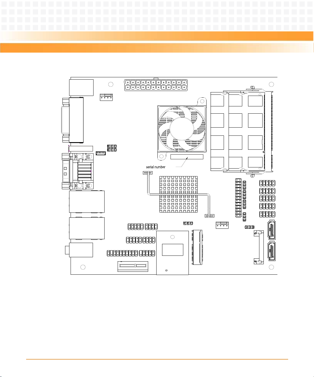
1.5 Product Identification
The following graphic shows the location of the serial number label on the board.
Figure 1-2 Single Core Processor Board - Serial Number Location
28
MITX-430/MITX-440-DVI-2E Installation and Use Guide (6806800K37B)
Page 29
Introduction
Figure 1-3 Dual Core Processor Board -Serial Number Location
MITX-430/MITX-440-DVI-2E Installation and Use Guide (6806800K37B)
29
Page 30

Introduction
30
MITX-430/MITX-440-DVI-2E Installation and Use Guide (6806800K37B)
Page 31

Hardware Preparation and Installation
2.1 Environmental and Power Requirements
The following environmental and power requirements are applicable to the motherboard.
2.1.1 Environmental Requirements
You must make sure that the motherboard, when operated in your particular system
configuration, meets the environmental requirements specified below.
Operating temperatures refer to the temperature of the air circulating around the
motherboard and not to the component temperature.
Chapter 2
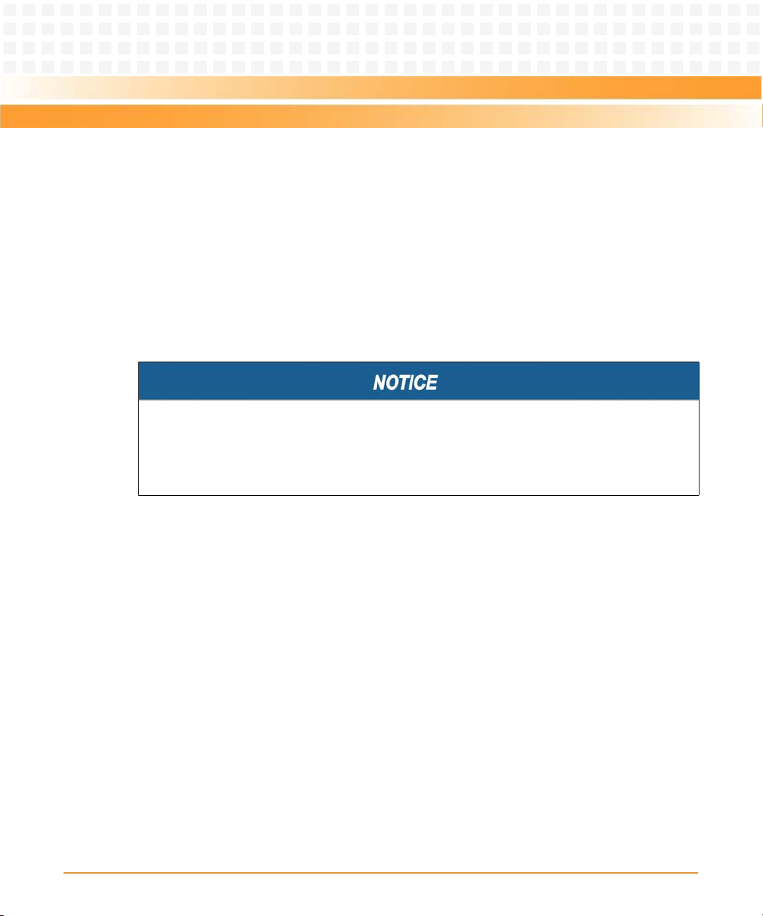
Product Damage
High humidity and condensation on surfaces cause short circuits.
Do not operate the product outside the specified environmental limits. Make sure the
product is completely dry and there is no moisture on any surface before applying power.
Overheating and Damage of the Product
Operating the product without forced air cooling can lead to overheating and thus damage
of the product.
When operating the product, make sure that forced air cooling is available in the shelf.
Table 2-1 Environmental Requirements
Requirement Operating Non-operating
o
Tem pe ra tu re 0
Humidity 10% to 90% non-condensing 5% to 95% non condensing
Vibration 0.01g^2/Hz at 5-500Hz random
C to 55oC with CPU cooler -40oC to 85oC
vibration
MITX-430/MITX-440-DVI-2E Installation and Use Guide (6806800K37B)
31
Page 32

Hardware Preparation and Installation
Table 2-1 Environmental Requirements (continued)
Requirement Operating Non-operating
Shock 20G peak (half sine)
Altitude -60 to 4000 m ASL
2.1.2 Thermal Requirements
Table 2-2 Critical Temperature Spots
Item Thermal Dissipation Power (W) Maximum Allowable Temperature (0C)
CPU D510 <= 13W
D410 <= 10W
ICH8-M 3W 92 (Tc)
11ms
100 (Tj)
System Overheating
Cooling Vents
Improper cooling can lead to system damage and can void the manufacturer's warranty. To
ensure proper cooling and undisturbed airflow through the system do not obstruct the
ventilation openings of the system. Make sure that the fresh air supply is not mixed with hot
exhaust from other devices.
32
MITX-430/MITX-440-DVI-2E Installation and Use Guide (6806800K37B)
Page 33

Hardware Preparation and Installation
Personal Injury
Du ring o pera tion, hot su rfa ces m ay be p rese nt on the heat sinks and th e comp onen ts of t he
product. To prevent injury from hot surface do not touch any of the exposed components
or heatsinks on the product. Use the handle and face plate, where applicable, or the board
edge when removing the product from the enclosure.
2.1.3 Power Requirements (Single Core Processor Board)
The power consumption is tested under the following conditions with:
z 1*2G memory
z 1*1G memory
z One 2.5" ATA HDD
z One infonion TPM module
z One 3.5" SATA HDD
z One SATA CD-ROM
z One USB keyboard
z One USB mouse
z One PS/2 keyboard
z One PS/2 mouse
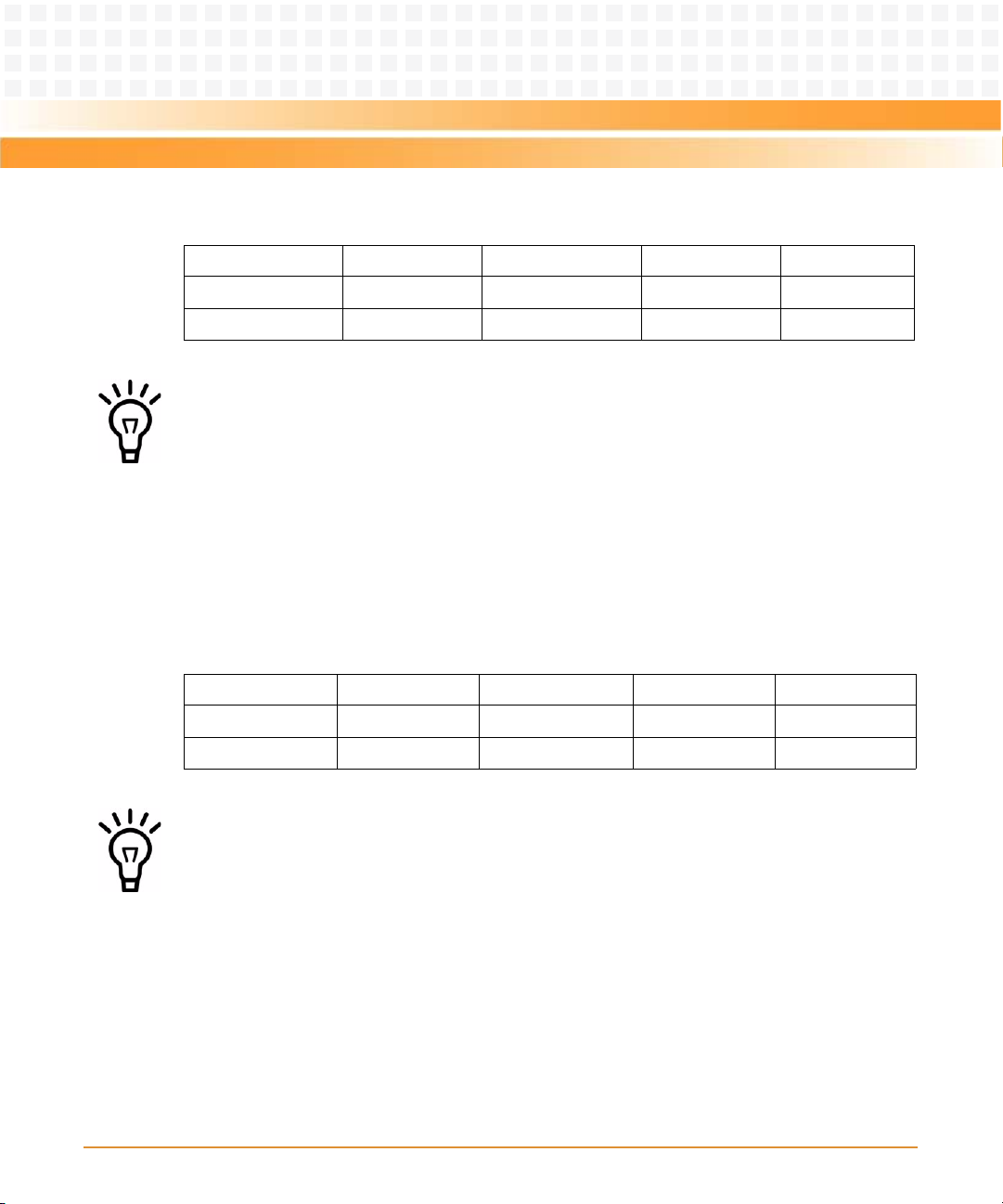
2.1.3.1 Full Loading Running Burn-in Test
VGA display only
12V 5V 3.3V Total
Current(A) 0.30 1.8 0.3
Power(W) 3.6 9 0.99 13.59
MITX-430/MITX-440-DVI-2E Installation and Use Guide (6806800K37B)
33
Page 34
Hardware Preparation and Installation
VGA + LVDS dual display
12V 5V 3.3V Total
Current(A) 0.88 1.8 0.67
Power(W) 10.56 9 2.21 21.77
z Tested with 12.1" LCD Panel (P/N: G121X1-L01). The LCD inverter uses 12V.
z The test devices do not include PCIE x1 add-in card and Mini-PCIE card. The two SATA
devices are powered externally. If you use all the devices and power internally, then you
must add all the power consumption.
z It is recommended to add more buffer while designing the ATX power supply.
2.1.3.2 Idle Mode Power Consumption
VGA + LVDS dual display
12V 5V 3.3V Total
Current(A) 0.78 1.7 0.73
Power(W) 9.76 8.5 2.4 20.66
z Tested with 12.1" LCD Panel (P/N: G121X1-L01). The LCD inverter uses 12V.
z The test devices do not include PCIE x1 add-in card and Mini-PCIE card. The two SATA
devices are powered externally. If you use all the devices and power internally, then you
must add all the power consumption.
z It is recommended to add more buffer while designing the ATX power supply.
34
MITX-430/MITX-440-DVI-2E Installation and Use Guide (6806800K37B)
Page 35
Hardware Preparation and Installation
2.1.3.3 Standby Mode Power Consumption
2.1.3.3.1 S3 Sleep Mode
5V standby
Current(A) 0.3
Power(W) 1.5
2.1.3.3.2 S5 Sleep mode
5V standby
Current(A) 0.23
Power(W) 1.15
2.1.4 Power Requirements (Dual Core Processor Board)
The power consumption is tested under the following conditions with:
z 2*2G SO-DIMM
z One 2.5” ATA HDD
z One infonion TPM module
z One USB keyboard
z One USB mouse
z One PS/2 keyboard
z One PS/2 mouse
z One 3.5” SATA HDD
z One 3.5” SATA CD-ROM
MITX-430/MITX-440-DVI-2E Installation and Use Guide (6806800K37B)
35
Page 36

Hardware Preparation and Installation
2.1.4.1 Full Loading Running Burn-in Test
VGA and LVDS dual display, without DVI display.
12V 5V 3.3V Total (W)
Current (A) 1.18 2.25 1
Power (W) 14.16 11.25 3.3 28.71
Source ATX ATX ATX
z Tested with 12.1" LCD Panel (P/N: G121X1-L01). The LCD inverter uses 12V.
z The test devices do not include PCIE x1 add-in card and Mini-PCIE card. The two SATA
devices are powered externally. If you use all the devices and power internally, then you
must add all the power consumption.
z It is recommended to add more buffer while designing the ATX power supply.
2.1.4.2 Idle Mode Power Consumption
VGA and LVDS dual display, without DVI display, tested 1minute after logging in Windows XP.
12V 5V 3.3V Total (W)
Current (A) 0.96 2.03 1.1
Power (W) 11.52 10.15 3.63 25.3
So u rce AT X AT X ATX
z Tested with 12.1" LCD Panel (P/N: G121X1-L01). The LCD inverter uses 12V.
z The test devices do not include PCIE x1 add-in card and Mini-PCIE card. The two SATA
devices are powered externally. If you use all the devices and power internally, then you
must add all the power consumption.
z It is recommended to add more buffer while designing the ATX power supply.
36
MITX-430/MITX-440-DVI-2E Installation and Use Guide (6806800K37B)
Page 37

Hardware Preparation and Installation
2.1.4.3 Standby Mode Power Consumption
2.1.4.3.1 S3 state
5V standby
Current(A) 0.19
Power(W) 0.95
Source ATX
2.1.4.3.2 S5 State
5V standby
Current(A) 0.13A
Power(W) 0.65
Source ATX
2.2 Board Thermal Management and Placement
2.2.1 Board Thermal Management
The motherboard provides some thermal management strategy, including CPU junction
temperature monitor. It can take corresponding action to protect system at catastrophic
overheating.
MITX-430/MITX-440-DVI-2E Installation and Use Guide (6806800K37B)
37
Page 38

Hardware Preparation and Installation
Figure 2-1 shows the thermal management diagram.
Figure 2-1 Board Thermal Management
Two PNP thermal transistors are integrated in Pineview-D processor. It is used as a diode and
connects to an external digital thermal sensor EMC2103. CPU receives the data of junction
temperature through SMBus. Note that, this is an inaccurate value and the temperature offset
must be taken into account by reading MSR of CPU.
When the CPU junction temperature is more than 125C, CPU asserts the THERMTRIP# signal,
and then stops all bus activities, and the core power must be shut down in the specified time.
38
MITX-430/MITX-440-DVI-2E Installation and Use Guide (6806800K37B)
Page 39

Hardware Preparation and Installation
2.3 Unpacking and Inspecting the Board
Damage of Circuits
Electrostatic discharge and incorrect installation and removal of the product can damage
circuits or shorten their life.
Before touching the product make sure that your are working in an ESD-safe environment
or wear an ESD wrist strap or ESD shoes. Hold the product by its edges and do not touch any
components or circuits.
Shipment Inspection
To inspect the shipment, follow the steps mentioned below:
1. Verify that you have received all items of your shipment:
z Quick Start Guide and Safety Notes summary
z Motherboard
z Two COM cables
z One SATA power cable
z One SATA data cable
z Driver CD
z I/O Shield
MITX-430/MITX-440-DVI-2E Installation and Use Guide (6806800K37B)
39
Page 40

Hardware Preparation and Installation
2. Check for damage and report any damage or differences to the customer service.
3. Remove the desiccant bag shipped together with the product.
Environmental Damage
Improper disposing of used products may harm the environment. Always dispose of used
products according to your country’s legislation and manufacturer’s instructions.
2.4 Preparing the Installation Environment
Before you install or replace components, pay attention to the following:
z Wear an ESD-preventive wrist strap to prevent the static electricity from damaging the
device.
z Keep the area where the components reside clean and keep the components away from
heat-generating devices, such as radiator.
z Ensure that your sleeves are tightened or rolled up above the elbow. For safety purposes,
it is not recommended to wear jewelry, watch, glasses with metal frame, or clothes with
metal buttons.
z Do not exert too much force, or insert or remove the components forcibly. Avoid damage
to the components or plug-ins.
z Confirm the feasibility of the operation
The spare parts of the components to be installed or replaced are available in the
equipment warehouse. When the available spare parts are lacking, contact Emerson
Network Power. For details on how to get help from Emerson Network
Power, visit http://www.emersonnetworkpower.com/embeddedcomputing.
Make sure that the new components are in good condition, without defects such as
oxidation, chemical corrosion, missing components, or transportation damage.
z Check the environment
Make sure that the power supply, temperature, and humidity meets the operating
requirements for the motherboard and its components. For details, refer to the respective
system documentation.
z Prepare the parts and the tools
40
MITX-430/MITX-440-DVI-2E Installation and Use Guide (6806800K37B)
Page 41

Hardware Preparation and Installation
Prepare the components to be installed or replaced.
When you hold or transport the components, use the special antistatic package.
Prepare the cross screwdriver, screws, plastic supports, cooling gel, and ESD-preventive
wrist strap.
z Confirm installation or changing position
Confirm the position where the MITX-430/MITX-440-DVI-2E will be installed.
z Others
If a serious problem occurs and cannot be solved when you install or replace the
component, contact Emerson Network Power for technical support.
2.5 Processor Cooler Installation and Removal
Installing the Processor Cooler
1. Wear the ESD-preventive wrist strap.
2. Tear down the thermal pad resistant paper from back of the cooler.
3. Adjust the optimal installation direction for cooler. Place the cooler over the processor and
align the two push-pins to the holes on the motherboard.
4. Push the two pins down and make sure that each of the push-pin is inserted correctly into
the hole and properly locked on the motherboard.
5. Connect the fan to its connector on the motherboard.
Removing the Processor Cooler
1. Wear the ESD-preventive wrist strap.
2. Disconnect the fan from the motherboard.
3. Turn over the motherboard to backside. Locate the cooler pins, pinch the ends of the push
tabs and push them out of the hole.
MITX-430/MITX-440-DVI-2E Installation and Use Guide (6806800K37B)
41
Page 42
Hardware Preparation and Installation
2.6 Memory Module Installation and Removal
When you install or replace the module, pay attention to the following:
z The MITX-430/MITX-440-DVI-2E supports single channel DDR2 667MHz, two SO-DIMM
slots.
z The SO-DIMMs must have the same sizes, frequencies, types and technologies, physical
designs, and manufacturers.
z SO-DIMMs must be of single or dual rank type. Quad rank type modules are not
supported.
Pin Damage
Forcing the module into the system may damage connector pins. If the module hangs
during insertion, pull it out and insert it again.
Installing Memory Module
1. Wear the ESD-preventive wrist strap.
2. Lay the MITX-430/MITX-440-DVI-2E, where the SO-DIMM is to be installed on the
antistatic desktop.
3. Take the SO-DIMM out of the antistatic package, holding it by the edges.
4. Line up the notch located on the row of the metal pins at the bottom of the module with
the key in the SO-DIMM slot on the motherboard.
5. Insert the SO-DIMM in a slantwise position or at a 45
6. Press down on the module against the motherboard until you hear it snap into place. The
modules must be properly aligned before you press it down into its final position. Remove
the module from the socket and reinstall it if you cannot press it down into its final
position.
42
MITX-430/MITX-440-DVI-2E Installation and Use Guide (6806800K37B)
o
angle to slide the module into place.
Page 43

Hardware Preparation and Installation
Removing Memory Module
1. Wear the ESD-preventive wrist strap.
2. Release the module from the slot by pushing the spring latches on either side of the
module outward.
3. Lift the module from the motherboard.
Damage of the Product and Additional Devices and Modules
Incorrect installation or removal of additional devices or modules damages the product or
the additional devices or modules.
Before installing or removing additional devices or modules, read the respective
documentation and use appropriate tools.
MITX-430/MITX-440-DVI-2E Installation and Use Guide (6806800K37B)
43
Page 44

Hardware Preparation and Installation
44
MITX-430/MITX-440-DVI-2E Installation and Use Guide (6806800K37B)
Page 45
Controls, LEDs, and Connectors
BIOS socket
(far side)
3.1 Board Layout
Figure 3-1shows the location of the major components on the motherboard.
Figure 3-1 Single Core Motherboard Components
Chapter 3
MITX-430/MITX-440-DVI-2E Installation and Use Guide (6806800K37B)
45
Page 46
Controls, LEDs, and Connectors
Figure 3-2 Dual Core Motherboard Components
BIOS socket
(far side)
46
MITX-430/MITX-440-DVI-2E Installation and Use Guide (6806800K37B)
Page 47
Controls, LEDs, and Connectors
3.2 Connectors
The following subsections describe the connectors used on the board.
3.2.1 Clear CMOS (P3)
Table 3-1 Clear CMOS
Header Mode
1-2 short Clear CMOS
3.2.2 LVDS Header (J5)
Table 3-2 LVDS Header Pin Definition
PIN PIN Name PIN PIN Name
1 VCC_LVDS 2 VCC_LVDS
3 GND 4 GND
5 LVDS_A_A0_P 6 LVDS_A_CLK_P
7 LVDS_A_A0_N 8 LVDS_A_CLK_N
9GND10GND
11 LVDS_A_A1_P 12 LDDC_CLK
13 LVDS_A_A1_N 14 LDDC_DATA
15 GND 16 GND
17 LVDS_A_A2_P 18 NC
19 LVDS_A_A2_N 20 NC
MITX-430/MITX-440-DVI-2E Installation and Use Guide (6806800K37B)
47
Page 48

Controls, LEDs, and Connectors
3.2.3 LVDS Backlight Header (P23)
Table 3-3 LVDS Backlight Header PIn Definition
PIN PIN Name
1VCC12V
2LVDS_BKLT_EN
3GND
4 LCD_BKL_ADJ
5VCC5V
3.2.4 LVDS Power
Header P5 selects the power of LCD Panel.
Table 3-4 LVDS Power
HEADER MODE
1-2 short 3.3V (default)
2-3 short 5V
3.2.5 MINI IDE Header (J8)
Table 3-5 MINI IDE Header PIN Definition
PIN PIN Name PIN PIN Name
1 IDE_RST_R_N 2 GND
3IDE_D74 IDE_D8
5IDE_D66 IDE_D9
7IDE_D58 IDE_D10
48
MITX-430/MITX-440-DVI-2E Installation and Use Guide (6806800K37B)
Page 49

Controls, LEDs, and Connectors
Table 3-5 MINI IDE Header PIN Definition (continued)
PIN PIN Name PIN PIN Name
9 IDE_D4 10 IDE_D11
11 IDE_D3 12 IDE_D12
13 IDE_D2 14 IDE_D13
15 IDE_D1 16 IDE_D14
17 IDE_D0 18 IDE_D15
19 GND 20 NC
21 IDE_REQ 22 GND
23 IDE_IOW_N 24 GND
25 IDE_IOR_N 26 GND
27 IDE_IORDY 28 IDE_SEL
29 IDE_ACK_N 30 GND
31 IDE_IRQ 32 NC
33 IDE_A1 34 IDE_DET
35 IDE_A0 36 IDE_A2
37 IDE_CS1_N 38 IDE_CS3_N
39 IDE_ACT_N 40 GND
41 VCC5V 42 VCC5V
43 GND 44 GND
3.2.6 USB Flash Header (P10)
Table 3-6 USB Flash Header Pin Definition
PIN PIN Name PIN PIN Name
1 VCC5V 2 VCC5V
3USB0_N4 USB1_N
5USB0_P6 USB1_P
MITX-430/MITX-440-DVI-2E Installation and Use Guide (6806800K37B)
49
Page 50

Controls, LEDs, and Connectors
Table 3-6 USB Flash Header Pin Definition (continued)
PIN PIN Name PIN PIN Name
7GND8 GND
9KEY10 NC
3.2.7 USB Header (P12)
Table 3-7 USB Header Pin Definition
PIN PIN Name PIN PIN Name
1 VCC5V 2 VCC5V
3 USB0_N 4 USB1_N
5 USB0_P 6 USB1_P
7 GND 8 GND
9KEY10GND
3.2.8 ELO Touch Screen Header (P6)
Table 3-8 ELO Touch Screen Header Pin Definition
PIN PIN Name PIN PIN Name
1 VCC5V 2 VCC5V
3USB_N4 GND
5USB_P6 NC
7GND8 KEY
50
MITX-430/MITX-440-DVI-2E Installation and Use Guide (6806800K37B)
Page 51

Controls, LEDs, and Connectors
3.2.9 GPIO Header (P4)
Table 3-9 GPIO Header Pin Definition
PIN PIN Name PIN PIN Name
1GPO02 GPI0
3GPO14 GPI1
5GPO26 GPI2
7GPO38 GPI3
9 VCC5DUAL 10 GND
3.2.10 COM Header (P9, P27)
Table 3-10 COM3, COM6 Header Pin Definition
PIN PIN Name PIN PIN Name
1DCD2RXD
3TXD4DTR
5GND6DSR
7 RTS 8 CTS
9RING10KEY
3.2.11 RS-232/422/485 (P18)
Table 3-11 RS-232/422/485 Header Pin Definition
PIN PIN Name
1 RS422TX_N
MITX-430/MITX-440-DVI-2E Installation and Use Guide (6806800K37B)
51
Page 52

Controls, LEDs, and Connectors
Table 3-11 RS-232/422/485 Header Pin Definition (continued)
PIN PIN Name
2 RS422TX_P
3 RS422RX_485DAT_P
4 RS422RX_485DAT_N
5GND
Table 3-12 RS-232/422/485 Jumper Selection (P28)
PIN PIN Name
1-2 short RS-232
2-3 short RS422/RS-485
3.2.12 Power COM (P8, P26)
Table 3-13 COM4, COM5 Header Pin Definition
PIN PIN Name PIN PIN Name
1DCD 2 RXD
3TXD 4 DTR
5GND6 DSR
7RTS 8 CTS
9 Pin9 Select 10 KEY
Table 3-14 COM4, COM5 Pin9 Selection
PIN PIN Name
P19 1-2 short COM4 Pin9 is Ring
P19 2-3 short
P20 1-2 short
52
COM4 Pin9 is 5V
MITX-430/MITX-440-DVI-2E Installation and Use Guide (6806800K37B)
Page 53

Controls, LEDs, and Connectors
Table 3-14 COM4, COM5 Pin9 Selection (continued)
PIN PIN Name
P19 2-3 short
P20 2-3 short
P21 1-2 short COM5 Pin9 is Ring
P21 2-3 short
P22 1-2 short
P21 2-3 short
P22 2-3 short
3.2.13 TPM Header (P2)
Table 3-15 TPM Header Pin Definition
PIN PIN Name PIN PIN Name
1PCI_CLK2GND
3LPC_FRAME4KEY
5 TPM_RST# 6 VCC5V
7 LPC_AD3 8 LPC_AD2
9 VCC3V3 10 LPC_AD1
11 LPC_AD0 12 GND
13 SMB_CLK 14 SMB_DAT
COM4 Pin9 is 12V
COM5 Pin9 is 5V
COM5 Pin9 is 12V
15 VCC3V3DUAL 16 LPC_SERIRQ#
17 GND 18 CLKRUN#
19 TPM_LPC_PD# 20 TPM_LDRQ#
MITX-430/MITX-440-DVI-2E Installation and Use Guide (6806800K37B)
53
Page 54

Controls, LEDs, and Connectors
3.2.14 LPT Header (P11)
Table 3-16 LPT Header Pin Definition
PIN PIN Name PIN PIN Name
1STB# 2 PD0
3 PD1 4 PD2
5 PD3 6 PD4
7 PD5 8 PD6
9PD7 10 ACK#
11 BUSY# 12 PE#
13 SLCT# 14 AFD#
15 ERR# 16 INIT#
17 SLIN# 18 GND
19 GND 20 GND
21 GND 22 GND
23 GND 24 GND
25 GND 26 KEY
3.2.15 Front Panel Header (P15)
Table 3-17 Front Panel Header Pin Definition
PIN PIN Name PIN PIN Name
1 HDD_LED_PWR 2 PWR_LED
3HDD_LED_N4 GND
5GND6 POWER BUTTON#
7 SYSTEM RST# 8 GND
54
MITX-430/MITX-440-DVI-2E Installation and Use Guide (6806800K37B)
Page 55

Controls, LEDs, and Connectors
Table 3-17 Front Panel Header Pin Definition (continued)
PIN PIN Name PIN PIN Name
9 STANDBY LED PWR 10 STANDBY LED
3.2.16 BIOS Program Header (P16)
Table 3-18 BIOS Program Header Pin Definition
PIN PIN Name PIN PIN Name
1 VCC3V3DUAL 2 GND
3SPI_CS0#4 SPI_CLK
5 SPI_MISO 6 SPI_MOSI
7NC 8 NC
3.2.17 Fan Header (P1, P13)
Table 3-19 Smart Fan Header Pin Definition
PIN PIN Name
1GND
2VCC12V
3TACH
4PWM
MITX-430/MITX-440-DVI-2E Installation and Use Guide (6806800K37B)
55
Page 56

Controls, LEDs, and Connectors
3.2.18 MINI PCIE LED (P14)
Table 3-20 MINI PCIE Wireless LAN LED Header Pin Definition
PIN PIN Name
1VCC3V3
2WWAN_LED#
3WLAN_LED#
4GND
3.2.19 Case Open Header (P25)
Table 3-21 Case Open Header Pin Definition
PIN PIN Name
1Case_open#
2GND
56
MITX-430/MITX-440-DVI-2E Installation and Use Guide (6806800K37B)
Page 57
Functional Description
Intel®
Atom™ D410
or D510
Processor
Intel®
82801HBM
I/O Co n tro lle r
SuperIO/
Voltage Mon.
W83627
SO-DIMM
VGA
Mux
Interna l LVDS
Conn
LVDS De-
serializer
TMDS
Transmitter
DVI-D
Audio
CODEC
ALC888
Audio
1GbE
PHY
82567
Ethernet
eSATA
4x USB
1GbE
MAC/
PHY
82574L
Ethernet
TPM
Header
2x
PS/2
LPT
Printer
2x RS-232
COM Port
4x RS-232
Headers
Interna l
SATA
Interna l
SATA
Intern al
USB
Interna l
USB
PCIe Minicard
(WiFi/W iMax)
Interna l
USB
AMI Aptio
EFI FW
Pwr/Rst/
LED Header
IDE
VGA
DDR2 667 64-bit
LVDS[2:0 ]
CLK
DVI-D
TMDS
18
Mic
HD Audio
1GbE
GLCI
eSATA
Line-ou t
Line-in
1GbE
PCIe x1
LPC
PS2 KB
PS2 MS
4x USB
LPT
(opt.)
2xUART
PS 3V
PS 5V
PS 12V
4xUART
IDE
Pwr/R st /L E D
SPI
USB
PCIe x 1
USB
2xUSB
2xUSB
SATA
SATA
PCIe x1
DMI
XDP
JTAG
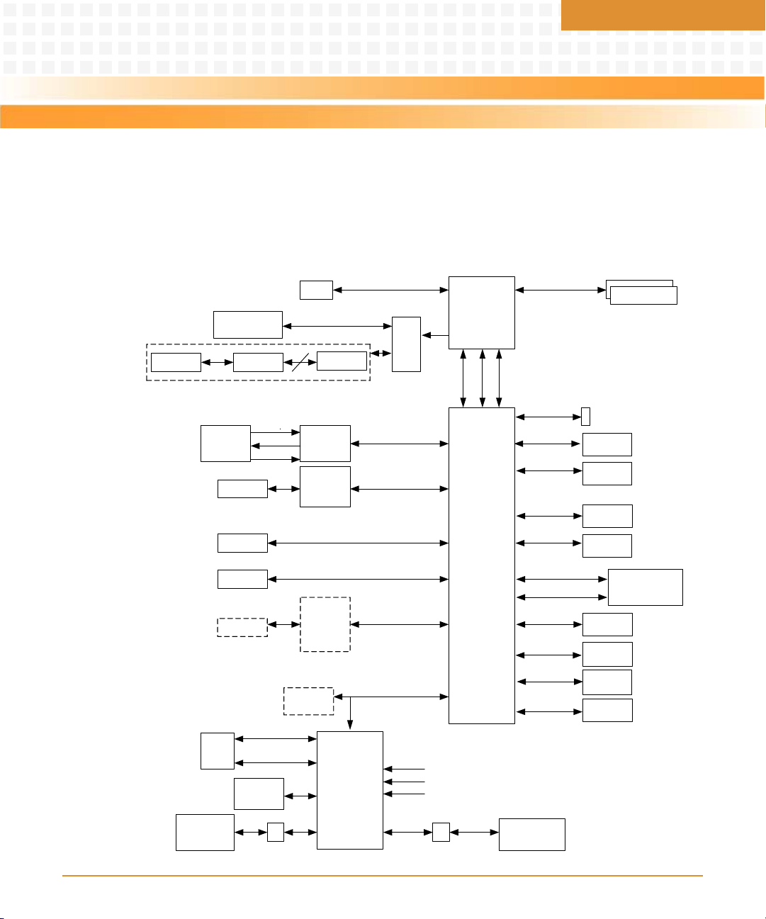
4.1 Block Diagram
Figure 4-1 provides an overview of the main functional blocks of the motherboard and how
they are interconnected.
Figure 4-1 Motherboard Block Diagram
Chapter 4
MITX-430/MITX-440-DVI-2E Installation and Use Guide (6806800K37B)
57
Page 58

Functional Description
4.2 Pineview-D Processor
The MITX-430/MITX-440-DVI-2E is designed to support the Pineview-D processor. The
processor features are as follows:
z Single chip integrated processor, memory controller, graphic controller with small size of
22mm x 22mm.
z Manufactured on 45nm process.
z 2 x 512KB L2 cache for D510 dual-core processor, 1 x 512KB L2 cache for D410 single-core
processor, 32KB instruction cache, and 24KB data cache.
z Single channel DDR2 667MT/s, memory support up to 4GB, 64bit.
z Improved graphic engine with render core frequency at 400MHz.
— Supports DirectX 9.0c and OpenGL 1.5.
— Supports VGA port and 18bit LVDS.
z DMI link to ICH8-M.
z Supports C0 and C1 power states.
z Supports Intel thermal monitor with Adaptive Thermal Monitor 2 Enhancement.
z Enhanced Intel SpeedStep technology.
z Less TDP of 15W.
4.3 SMBus Interface and Devices
There is an SMBus on ICH8-M, which is I2C compatible. The following devices connect to
SMBus:
z WG82574L LAN controller
z PCIEx1 slot
z Mini PCIE slot
z TPM header
z W83627UHG SIO
z PCA9557PW GPIO
58
MITX-430/MITX-440-DVI-2E Installation and Use Guide (6806800K37B)
Page 59

Functional Description
z EMC2103-2-AP CPU thermal sensor
z 9LPR501SGLFT CLK GEN
z Memory slot
z XDP header
Figure 4-2 shows the SMBus device connection diagram.
Figure 4-2 Board I2C Device Connection
MITX-430/MITX-440-DVI-2E Installation and Use Guide (6806800K37B)
59
Page 60
Functional Description
I2C device address is given in the table below:
Table 4-1 I2C Device Address
Device CK505* SPD0 SPD1 EMC2103* PCA9557 82574L W83627UHG
Address D2 A0 A2 5C 30 C2 5A
4.4 System Memory
The Pineview-D integrates a single channel 64bit non ECC DDR2 controller.
There are two 200pin SO-DIMM slots on MITX-430/MITX-440-DVI-2E, and supports up to 4GB
(assuming 2Gb density device technology) DDR2 memory at data transfer rate of 667MT/s.
4.5 Ethernet Interfaces
The MITX-430/MITX-440-DVI-2E provides two 10/100/1000 Ethernet, WG82567V and
WG82574L.
The WG82567V MAC is integrated in ICH8-M and uses WG82567V as GBE PHY. The connection
interface is GLCI between ICH8-M and WG82567V, and it occupies the PCIE port 6.
The WG82574L is a MAC and PHY GBE solution. The connec tion interface for WG82574L is PCIE
port 3.
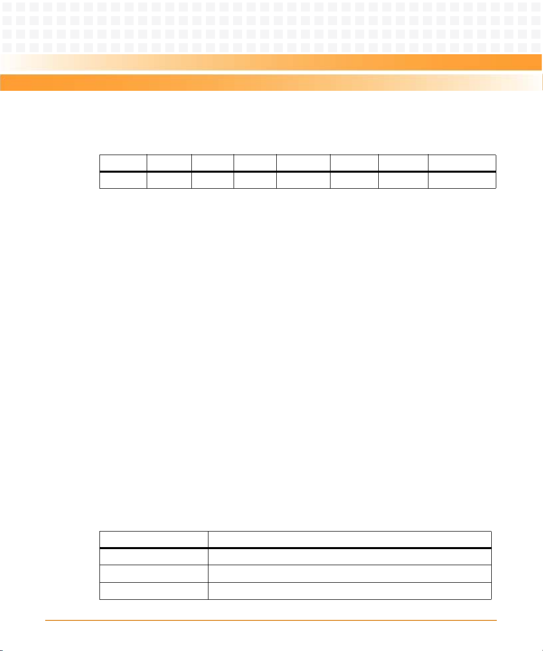
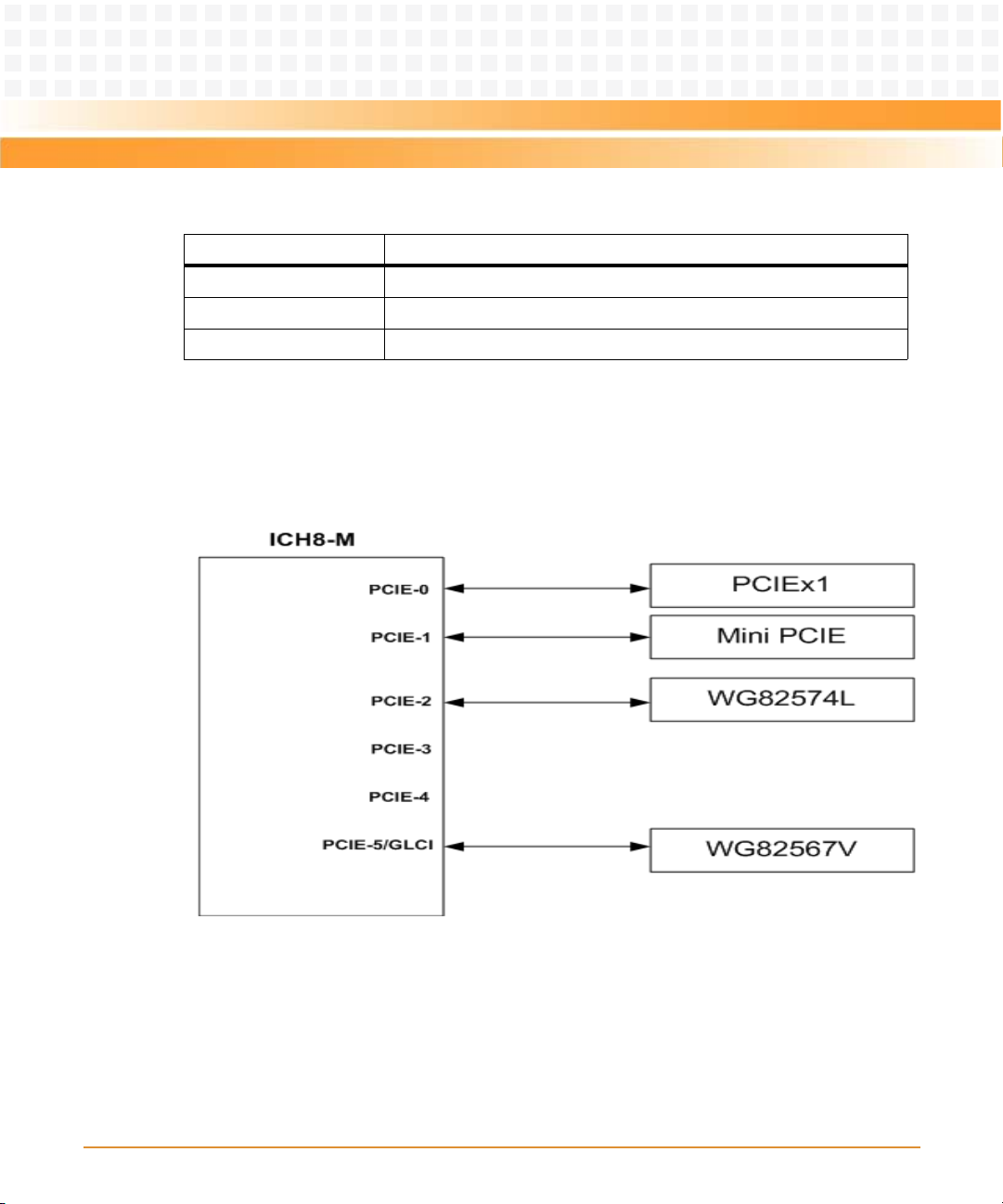
4.6 PCI-E Port
There are total six PCI-E ports in ICH8-M, and Table 4-2 shows the PCI-E ports configuration.
Table 4-2 PCI-E Port
Port Configuration
1 Connects to PCIEx1 slot
2 Connects to Mini PCIE slot
3 Connects to WG82574L
60
MITX-430/MITX-440-DVI-2E Installation and Use Guide (6806800K37B)
Page 61
Functional Description
Table 4-2 PCI-E Port (continued)
Port Configuration
4Unused
5Unused
6Used as GLCI
The PCIE supports 2.5G transmission rate.
Figure 4-3 shows the PCI-E connection diagram.
Figure 4-3 PCI-E Connection
4.7 USB Interface
The ICH8-M supports 10 USB2.0 interface using UHCI or EHCI. Four USB ports are routed to
USB+RJ45 connectors. Two USB ports are routed to USB headers, two for USB flash disk, and
one for ELO Touch Screen Module. One is routed to Mini PCIE slot.
MITX-430/MITX-440-DVI-2E Installation and Use Guide (6806800K37B)
61
Page 62

Functional Description
Figure 4-4 shows the routing diagram.
Figure 4-4 USB Ports Connection
4.8 VGA, LVDS, LPC, and Audio Interface
A separate VGA and LVDS display interface is connected to connector from CPU.
The VGA supports resolution of 2048x1536 at 60Hz. The LVDS is a single channel with 18bit
color definition, and supports resolution up to 1366 x 768.
The LPC is routed to super IO and TPM connector.
ICH8-M supports a high definition audio interface and ALC888GR is used as the audio codec.
62
MITX-430/MITX-440-DVI-2E Installation and Use Guide (6806800K37B)
Page 63

Functional Description
4.9 DVI Interface
The DVI is switched and derived from LVDS, so DVI and LVDS cannot be used at the same time.
For display combination, use VGA + LVDS or VGA + DVI. Select the combination in the BIOS.
4.10 BIOS Device
A 4MB SPI Flash is used as BIOS device.
4.11 IDE
The MITX-430/MITX-440-DVI-2E supports a 44pin Mini-IDE header on board.
The IDE interface supports up to two IDE devices providing an interface for IDE hard disks and
ATAPI devices. Each IDE device has independent timings. The IDE interface supports PIO IDE
transfers up to 16 MB/sec and Ultra ATA transfers up to 100 MB/sec. It does not consume any
legacy DMA resources. The IDE interface integrates 16*32-bit buffers for optimal transfers.
The ICH8s IDE system contains a single, independent IDE signal channel that can be electrically
isolated. There are integrated series resistors on the data and control lines.
4.12 GPIO Configuration
There are two GPIOs:
z User defined GPIO which is generated from PCA9557PW
z ICH8-M GPIO
4.12.1 User Defined GPIO
4 GPI, 4 GPO 5V referenced. The 4 GPOs are internally pulled up to 5V with 10K resistor. The 4
GPIs are internally pulled down to GND with 10K resistor. The GPIO is controlled through SMBus
and the state of GPO is not lost even in S3 and S5 sleep state.
MITX-430/MITX-440-DVI-2E Installation and Use Guide (6806800K37B)
63
Page 64

Functional Description
4.12.2 ICH8-M GPIO
Table 4-3 describes the ICH8-M GPIO definition.
Table 4-3 ICH8-M GPIO Definition
Name Type Tolerance
GPIO0 I/O 3.3V Core GPI Multiplexed with
GPIO1 I/O 3.3V Core GPI Multiplexed with
Power
Well Default Signal Description Implementation
Unused, PU VCC3V3
BM_BUSY#
Used as IDE 80 pin
TAC H1
cable detect
GPIO2 I/OD 5V Core GPI Multiplexed with
PIRQ[H:E]#
GPIO3 I/OD 5V Core GPI Multiplexed with
PIRQ[H:E]#
GPIO4 I/OD 5V Core GPI Multiplexed with
PIRQ[H:E]#
GPIO5 I/OD 5V Core GPI Multiplexed with
PIRQ[H:E]#
GPIO6 I/O 3.3V Core GPI Unmultiplexed Used for board ID, PU
GPIO7 I/O 3.3V Core GPI Unmultiplexed Used for board ID, PU
GPIO8 I/O 3.3V Resume GPI Unmultiplexed Used as BIOS write
GPIO9 I/O 3.3V Resume GPI Multiplexed with
WOL_EN
GPIO10 I/O 3.3V Resume GPI Multiplexed with
SusPwrAck/ALERT#
GPIO11 I/O 3.3V Resume Native Multiplexed with
SMBALERT#
Unused, PU VCC3V3
Unused, PU VCC3V3
Unused, PU VCC3V3
Unused, PU VCC3V3
VCC3V3
VCC3V3
protect (WP) signal, PU
VCC3V3DUAL
Unused, PU
VCC3V3DUAL
Unused, PU
VCC3V3DUAL
Used for SMBus alert
signal, PU
VCC3V3DUAL
64
MITX-430/MITX-440-DVI-2E Installation and Use Guide (6806800K37B)
Page 65

Functional Description
Table 4-3 ICH8-M GPIO Definition (continued)
Power
Name Type Tolerance
GPIO12 I/O 3.3V Resume Native Natively used as
GPIO13 I/O 3.3V Resume Native Natively used as
Well Default Signal Description Implementation
GLAN_DOCK#
ENERGY_DETECT
Used as LAN_DISABLE#
signal, output low
active
Unused, PU
VCC3V3DUAL
GPIO14 I/O 3.3V Resume GPI Multiplexed with
AC_PRESENT
GPIO15
Desktop
only
GPIO16 I/O 3.3V Core Native Natively used as
GPIO17 I/O 3.3V Core GPI Multiplexed with
GPIO18 I/O 3.3V Core GPO Unmultiplexed Used as LVDS backlight
GPIO19 I/O 3.3V Core GPI Multiplexed with
GPIO20 I/O 3.3V Core GPO Unmultiplexed Unused, connect to a
GPIO21 I/O 3.3V Core GPI Multiplexed with
I/O 3.3V Resume Native GPIO is not
implemented
and is used instead
as
STP_PCI#.
DPRSLPVR.
TAC H0
SATA1GP
SATA0GP.
Unused, PU
VCC3V3DUAL
Used as STP_PCI#
Used as DPRSLPVR
Used as DVI detect
type selection
1 = DC mode; 0 = PWM
mode
Unused, PD GND
TP/used as a strap pin
Unused, PD GND
GPIO22 I/O 3.3V Core GPI Multiplexed with
GPIO23 I/O 3.3V Core Native Multiplexed with
MITX-430/MITX-440-DVI-2E Installation and Use Guide (6806800K37B)
SCLOCK
LDRQ1#
Unused, PU VCC3V3
By default unused,
optionally used as
LPC_DRQ1#,
connecting to TPM
connector
65
Page 66

Functional Description
Table 4-3 ICH8-M GPIO Definition (continued)
Power
Name Type Tolerance
GPIO24 I/O 3.3V Resume GPO Multiplexed with
Well Default Signal Description Implementation
MEM_LED
Unused, connect to a
TP
GPIO25
Desktop
only
GPIO26 I/O 3.3V Resume Native Multiplexed with
GPIO27 I/O 3.3V Resume GPO ICH8 Base:
GPIO28 I/O 3.3V Resume GPO ICH8 Base:
GPIO29 I/O 3.3V Resume Native Multiplexed with
GPIO30 I/O 3.3V Resume Native Multiplexed with
GPIO31 I/O 3.3V Resume Native Multiplexed with
GPIO32
Desktop
only
I/O 3.3V Resume Native This GPIO is not
implemented and is
used instead
as STP_CPU#
S4_STATE#
Unmultiplexed
Unmultiplexed
OC5#
OC6#
OC7#
I/O 3.3V Core GPO This GPIO is not
implemented and is
used instead
as CLKRUN#
Used as STP_CPU#
Unused, PD GND
Used as Mini-PCIE
Disable signal, Low
active
Used as LAN2 disable
signal, Low active
Used as USB OC func,
associated with USB4
USB5
Used as USB OC func,
associated with USB6
USB7
Used as USB OC func,
associated with USB6
USB7
Used as CLKRUN#
GPIO33 I/O 3.3V Core GPO Multiplexed with
GPIO34 I/O 3.3V Core GPO Multiplexed with
GPIO35 I/O 3.3V Core GPO Multiplexed with
66
Unused, low active
HDA_DOCK_EN#
Used as LVDS/DVI
HDA_DOCK_RST#
MITX-430/MITX-440-DVI-2E Installation and Use Guide (6806800K37B)
SATACLKREQ#
display selection
1 = DVI; 0 = LVDS
Used as SATA clock
request
Page 67

Functional Description
Table 4-3 ICH8-M GPIO Definition (continued)
Power
Name Type Tolerance
GPIO36 I/O 3.3V Core GPI Multiplexed with
Well Default Signal Description Implementation
SATA2GP
Unused, PD GND
GPIO37 I/O 3.3V Core GPI Mobile:Unmultiple
xed.
GPIO38 I/O 3.3V Core GPI Multiplexed with
SLOAD
GPIO39 I/O 3.3V Core GPI Multiplexed with
SDATAOUT0
GPIO40 I/O 3.3V Resume Native Multiplexed with
OC[4:1]#
GPIO41 I/O 3.3V Resume Native Multiplexed with
OC[4:1]#
GPIO42 I/O 3.3V Resume Native Multiplexed with
OC[4:1]#
GPIO43 I/O 3.3V Resume Native Multiplexed with
OC[4:1]#
GPIO44 N/A N/A N/A N/A Not implemented NC
GPIO45 N/A N/A N/A N/A Not implemented NC
GPIO46 N/A N/A N/A N/A Not implemented NC
Unused, PD GND
Unused, PU VCC3V3
Unused, PU VCC3V3
Used as USB OC func,
associated with USB0
USB1
Used as USB OC func,
associated with USB2
USB3
Used as USB OC func,
associated with USB2
USB3
Used as USB OC func,
associated with USB4
USB5
GPIO47 N/A N/A N/A N/A Not implemented NC
GPIO48 I/O 3.3V Core GPI Multiplexed with
GPIO49 I/O V_CPU_IO V_CPU_IONative Multiplexed with
GPIO50 I/O 5.5V Core Native Multiplexed with
GPIO51 I/O 3.3V Core Native Multiplexed with
MITX-430/MITX-440-DVI-2E Installation and Use Guide (6806800K37B)
SDATAOUT1
CPUPWRGD
REQ1#
GNT1#
Unused, PU VCC3V3
Used as CPUPWRGD
Unused, PU VCC3V3
Unused, connect to TP
67
Page 68

Functional Description
Table 4-3 ICH8-M GPIO Definition (continued)
Power
Name Type Tolerance
GPIO52 I/O 5.5V Core Native Multiplexed with
Well Default Signal Description Implementation
REQ2#
Unused, PU VCC3V3
GPIO53 I/O 3.3V Core Native Multiplexed with
GPIO54 I/O 5.5V Core Native Multiplexed with
GPIO55 I/O 3.3V Core Native Multiplexed with
4.13 Chipset
The MITX-430/MITX-440-DVI -2E is designed to use the Intel ICH8M I/O Hub. The ICH8 provides
extensive I/O support. Functions and capabilities are as follows:
z PCI Express Base Specification, supports Revision 1.1.
z PCI Local Bus Specification, supports Revision 2.3 for 33 MHz PCI operations.
z Supports ACPI Power Management Logic.
z Enhanced DMA controller, interrupt controller, and timer functions.
z Integrated serial ATA host controllers with independent DMA operation on up to three
ports.
z Integrated IDE controller supports Ultra ATA100/66/33.
z USB host interface with support for up to ten USB ports, five UHCI host controllers, two
EHCI high-speed USB 2.0 host controllers.
Used as a strap pin
GNT2#
Unused, PU VCC3V3
REQ3#
Used as a strap pin
GNT3#
z Integrated 10/100/1000 GbE MAC.
z System Management Bus (SMBus) Specification, Version 2.0 with additional support for
most I2C devices.
z Supports Intel high definition audio.
z Low Pin Count (LPC) interface.
z Supports Serial Peripheral Interface (SPI).
68
MITX-430/MITX-440-DVI-2E Installation and Use Guide (6806800K37B)
Page 69

Functional Description
4.14 Clock Generator
The MITX-430/MITX-440-DVI-2E contains a CK505 clock generator (ICS9LPR501) to provide
the clocks for various components.
4.15 Video
The graphic core is integrated in Pineview-D processor.
The GPU contains a refresh of 3rd generation graphics core, and improved GFX engine. The
GPU is a unified graphics driver which does end to end decode.
z Supports Directx* 9 compliant Pixel Shader* 2.0.
z Two display ports: LVDS and RGB.
— Single LVDS channel supporting resolution up to 1366 * 768, 18bpp.
— Analog RGB display output resolution up to 2048 * 1536 at 60 Hz.
z Intel® Dynamic Video Memory Technology support 4.0.
z Intel® Clear Video Technology.
— MPEG2 Hardware Acceleration
—ProcAmp
The MITX-430/MITX-440-DVI-2E supports dual-independent displays using the Intel PineviewD p roc essor 's I nte grate d Gr aph ics Con tro ller. T he d isp lay is LV DS o r VG A. Dur ing boo t, t he B IOS
detects whether a VGA monitor is attached or not. If VGA is attached, then the primary display
is VGA. If VGA is not detected, then BIOS defaults to LVDS.
4.16 Storage
z SATA
MITX-430/MITX-440-DVI-2E supports two SATA ports and one E-SATA port integrated
onboard which supports SATA Gen 2(3.0Gb/s).
Two SATA por ts are routed to internal connector and one is routed to the E-SATA port.
z USB Solid State Drive
MITX-430/MITX-440-DVI-2E supports one standard USB flash disk (2x5Pin, 2.54mmPitch).
MITX-430/MITX-440-DVI-2E Installation and Use Guide (6806800K37B)
69
Page 70

Functional Description
4.17 Super I/O
MITX-430/MITX-440-DVI-2E uses Winbond W83627UHG-LF as Super I/O.
z Serial Port
MITX-430/MITX-440-DVI-2E supports six serial ports:
— Two to DSUB-9 in rear I/O region
— One RS-232/422/485 port
— Two power COM
— One to 2x5Pin header
z Parallel Port
MITX-430/MITX-440-DVI-2E supports the parallel port integrated on board.
z PS/2
MITX-430/MITX-440-DVI-2E supports the PS/2 keyboard or mouse integrated on board.
4.18 HW Monitor
z Voltage monitor
MITX-430/MITX-440-DVI-2E uses W83627UHG hardware monitor as voltage monitor. It
implements voltage monitoring capability on 1.05V, 3.3V, 5V, 12V, and CPU core. Voltages
can be read in BIOS setup menu.
z Tem p er at ur e
MITX-430/MITX-440-DVI-2E uses EMC2103 to monitor the CPU temperature, and uses
W83627 hardware monitor to monitor the system temperature.
z Fan monitor and control
MITX-430/MITX-440-DVI-2E supports CPU fan and system fan speed control.
4.19 SPI Flash
MITX-430/MITX-440-DVI-2E uses onboard 4MB SPI flash part to store the firmware including
the BIOS and GBE.
70
MITX-430/MITX-440-DVI-2E Installation and Use Guide (6806800K37B)
Page 71

Functional Description
The SPI flash part type is AT25DF321A-SH-T from Atmel. The AT25DF321A-SH-T supports SPI,
and a high performance dual output SPI using four pins: serial clock, chipset select, serial data
I/O, and serial data out. SPI clock frequencies of up to 33MHz are supported.
4.20 Watchdog Timer
MITX-430/MITX-440-DVI-2E implements the watchdog timer feature. The SIO chipset is used
to implement the watchdog function that supports 1-255s or 1-255m watchdog.
4.21 Debug
MITX-430/MITX-440-DVI-2E implements three ways for debugging:
z VGA for text and graphic information output.
z RS232 for AMI debugger. It can set, modify, or check the breakpoint, register value, and so
on.
z Extended Debug Port (XDP) tool for processor run control and debug.
4.22 Power Management
MITX-430/MITX-440-DVI-2E supports ACPI S0, S3, S4, S5.
4.23 Manageability
MITX-430/MITX-440-DVI-2E does not support AMT feature.
4.24 RTC
MITX-430/MITX-440-DVI-2E supports a battery backed Real Time Clock (RTC). The ICH8
contains a Motorola MC146818A-compatible RTC with 256 bytes of battery backed RAM. The
RTC performs two key functions: keeping track of the time of day and storing system data, even
when the system is powered down. The RTC operates on a 32.768 KHz crystal and a 3V battery.
MITX-430/MITX-440-DVI-2E Installation and Use Guide (6806800K37B)
71
Page 72

Functional Description
The RTC also supports two lockable memory ranges. By setting bits in the configuration space,
two 8-byte ranges can be locked to read and write accesses. This prevents unauthorized
reading of passwords or other system security information.
The RTC also supports a data alarm that allows for scheduling a wakeup event up to 30 days in
advance, rather than just 24 hours in advance.
72
MITX-430/MITX-440-DVI-2E Installation and Use Guide (6806800K37B)
Page 73

Operation
5.1 POST
After power up or reset, the BIOS performs a self-test, POST, that attempts to determine if
further operation is possible and that the detected configuration is expected. This process
either completes normally or results in a warning or an error. The boot process does not stop
after a warning but displays a message on the primary display device.
To view all checkpoints generated by Aptio firmware, you require a checkpoint card, also
referred to as a POST Card or POST Diagnostic Card. These are LPC add-in cards that show the
value of I/O port 80h on a LED display.
5.2 Boot Process
While performing the functions of the traditional BIOS, Aptio 4.x core follows the firmware
model described by the Intel Platform Innovation Framework for EFI. The framework refers to
the following boot phases, which applies to various status code descriptions:
Chapter 5
z Security (SEC) - initial low-level initialization
z Pre-EFI Initialization (PEI) - memory initialization1
z Driver Execution Environment (DXE) - main hardware initialization2
z Boot Device Selection (BDS) - system setup, pre-OS user interface and selecting a bootable
device (CD/DVD, HDD, USB, Network, Shell, and so on)
5.3 Initiating Setup
During the boot, press the F2 key on the keyboard to launch the setup utility once the self-test
is complete and before searching for a boot device. If you exit setup without saving any
changes, the boot process continues with the search for a boot device. If changes are made,
the motherboard loads the new settings and resets, restarting the entire boot process.
MITX-430/MITX-440-DVI-2E Installation and Use Guide (6806800K37B)
73
Page 74

Operation
5.4 Setup Utility
The BIOS incorporates a setup utility that allows you to alter a variety of system options. This
section describes the operation of the utility by describing the various options available
through a set of hierarchical menus. Not all options are available with all products and some
depend on BIOS customizations.
The current settings are stored in the SPI FLASH NVRAM area and any changes can be copied
back to this area via the Exit menu.
To start the utility, press the F2 key during the early stages of POST after powerup. This
functionality operates with PS/2 keyboards, USB keyboards when enabled, and via the console
redirection facility when enabled.
Table 5-1 briefly describes the primary menus.
Table 5-1 Setup Utility
Menu Options
Main BIOS information and date and time.
Advanced Advanced features including ACPI, CPU, IDE, USB, HW
Chipset Features including Host Bridge and South Bridge.
Boot Boot mode and boot options.
monitoring and serial port settings.
Security Administrator's password.
Sav e & Exit S ave wi th or with out c hange s, lo ad or save d efau lt setting s,
5.4.1 Main Menu
Table 5-2 Main Menu
Field Description
BIOS Vendor BIOS vendor name.
Core Version Aptio core version.
74
and Boot Device Selection.
MITX-430/MITX-440-DVI-2E Installation and Use Guide (6806800K37B)
Page 75

Operation
Table 5-2 Main Menu (continued)
Field Description
Project Version Project name and its version.
Build Date BIOS build date.
System Language System setup language. Only English is available.
System Date Set the time and date in month/day/year format. To change these values, go
System Time
to each field and enter the desired value. Press the tab key to move fro m hour to
minute to second, or from month to day to year. There is no default value.
5.4.2 Advanced Menu
Table 5-3 Legacy OPROM Support
Field Description
Launch PXE OpROM Enable or disable boot option for Legacy Network Devices. Default option
is Disabled.
Table 5-4 Advanced Menu
Field Description
ACPI Settings System ACPI Parameters, see Table 5-5 on page 76.
Trusted Computing Trusted Computing settings, see Table 5-6 on page 76.
S5 RTC Wake Settings Enable the system to wake from S5 using RTC alarm, see Table 5- 7 on page
77.
CPU Configuration CPU Configuration Parameters, see Table 5-8 on page 77.
IDE Configuration Enter SATA device options settings, see Table 5-9 on page 78.
IGD- LCD Control Internal Graphics Device (IGD)-LCD control function, see Tab le 5- 10 on pag e
79.
USB Configuration USB configuration parameters, see Table 5-11 on page 80.
MITX-430/MITX-440-DVI-2E Installation and Use Guide (6806800K37B)
75
Page 76
Operation
Table 5-4 Advanced Menu (continued)
Field Description
EMC2103 H/W
Monitor
Super IO
Configuration
W83627UHG H/W
Monitor
Serial Port Console
Redirection
Monitor hardware status, see Table 5-12 on page 81.
System super IO chip parameters, see Table 5-13 on page 81.
Monitor hardware status, see Table 5-22 on page 86.
Serial Port Console Redirection, see Table 5-23 on page 86.
Table 5-5 ACPI Settings
Field Description
Enable ACPI Auto
Configuration
ACPI Sleep State Select the highest ACPI sleep state the system enters when the SUSPEND
Enable or disable BIOS ACPI Auto Configuration. Default option is Disabled.
button is pressed. The states are:
z Suspend Disabled
z S3 (Suspend to RAM)
Default state is S3 (Suspend to RAM).
76
Table 5-6 Trusted Computing
Field Description
TPM SUPPORT Enable or disable TPM function. Default value is Disable.
When the field is disabled in BIOS, OS does not show TPM function.
TPM State Turn TPM On or Off. Default state is Disabled.
Pending TPM operation Schedule TPM operation, default option is none.
Current TPM Status Information
MITX-430/MITX-440-DVI-2E Installation and Use Guide (6806800K37B)
Page 77

Operation
Table 5-6 Trusted Computing (continued)
Field Description
No TPM Hardware If no TPM is found.
TPM Enabled Status Show TPM status, Enabled or Disabled
TPM Active Status Show current state of the TPM, Activated or Deactivated.
TPM Owner Status Show current TPM Ownership state, Owned or UnOwned.
Table 5-7 S5 RTC Wake Setting
Field Description
Wake system with Fixed
time
Wake up hour Select 0-23, for example, enter 3 for 3AM and 15 for 3PM.
Wake up minute 0-59. Default value is 0.
Wake up second 0-59. Default value is 0.
Wake system with
Dynamic time
Wake up minute increase 1-5. Default value is 1.
Enable or disable system wake on alarm event. When enabled, system
wakes on the specified hr::min::sec.
Default value is Disabled.
Default value is 0.
Enable or disable system wake on alarm event. When enabled, system
wakes on the current time + Increase minute(s). Default value is
Disabled.
Table 5-8 CPU Configuration
Field Description
Processor Type
EMT64 EMT64
Processor Speed Processor speed
System Bus Speed System bus speed
MITX-430/MITX-440-DVI-2E Installation and Use Guide (6806800K37B)
77
Page 78

Operation
Table 5-8 CPU Configuration (continued)
Field Description
Ratio Status Ratio Status
Actual Ratio Actual ratio
Processor Stepping Processor stepping
Microcode Revision Microcode revision
L1 Cache RAM L1 Cache RAM
L2 Cache RAM L2 Cache RAM
Processor Core Processor Core
Hyper-Threading Enabled for Windows XP and Linux (OS optimized for Hyper-Threading
Technology) and Disabled for other OS (OS not optimized for HyperThreading Technology). Default value is Enabled.
Execute Disable Bit XD prevents certain classes of malicious buffer overflow attacks when
combined with a supporting OS (Windows Server 2003 SP1, Windows XP
SP2, SuSE Linux 9.2, RedHat Enterprise 3 Update 3). Default value is
Enabled.
C-States Enable or disable C1. Default value is Enabled.
78
Table 5-9 IDE Configuration
Field Description
PATA Master Port status
PATA Slave Port status
SATA Port 0 Port status
SATA Port 1 Port status
SATA Port 2 Port status
ATA /IDE Configuration Select ATA or IDE configuration. The configurations are:
z Disabled
z Compatible
z Enhanced
Default value is Enhanced.
MITX-430/MITX-440-DVI-2E Installation and Use Guide (6806800K37B)
Page 79

Operation
Table 5-9 IDE Configuration (continued)
Field Description
Configure SATA as Enhanced: you can select the IDE, AHCI mode.
Compatible: you can select the legacy IDE Channels as SATA Only, SATA
Pri, PATA Sec, PATA only.
Table 5-10 IGD-LCD Control
Field Description
DVMT Mode Select Select DVMT Mode or Fixed Mode.
Default value is DVMT Mode.
DVMT/FIXED Memory Select DVMT or FIXED mode memory size used by internal graphics
device: The memory sizes are:
z 128MB
z 256MB
z Maximum
Default value is 256MB.
IGD-Boot Type Select the V ideo Device which is activated during POST. This has no effect
if external graphic is present. The options are:
z VBIOS Default
z CRT
z LFP
z DVI
z CRT +LFP
z CRT +DVI
Default value is CRT +LFP.
Note that the optional value DVI and CRT+DVI are only for MITX-440-DVI-
2E.
LCD Panel Type Select LCD panel used by Internal Graphics Device by selecting the
appropriate setup item. The LCD panel types are:
z 800x600 LVDS
z 1024x768 LVDS
Default value is 1024x768 LVDS.
MITX-430/MITX-440-DVI-2E Installation and Use Guide (6806800K37B)
79
Page 80

Operation
Table 5-10 IGD-LCD Control (continued)
Field Description
LCD Mode Set LCD Mode as PWM Mode or DC Mode.
Default value is PWM Mode.
Table 5-11 USB Configuration
Field Description
USB Devices List of the USB devices attached.
Legacy USB Support Enables Legacy USB support. AUTO option disables legacy support if no
USB devices are connected. DISABLE option keeps USB devices available
only for EFI applications. Default value is Enabled.
EHCI Hand-off This is a workaround for OSs without EHCI hand-off support. The EHCI
ownership change should be claimed by EHCI driver. Default value is
Enabled.
Device Reset Timeout USB mass storage device Start Unit command timeout. The options are:
z 10 sec
z 20 sec
z 30 sec
z 40 sec
Default value is 20 sec.
80
Controller Timeout The time out value for control, bulk, and interrupt transfer. The options
are:
z 1sec
z 5 sec
z 10 sec
z 20 sec
z 30 sec
Default value is 20 sec.
MITX-430/MITX-440-DVI-2E Installation and Use Guide (6806800K37B)
Page 81

Operation
Table 5-12 EMC2103 H/W Monitor
Field Description
CPU Temperature CPU temperature.
CPU Fan Speed CPU fan speed.
CPU Fan Duty Cycle CPU fan duty cycle.
Automatic Fan Control Enable or disable the CPU fan speed control. Default value is Enabled.
Table 5-13 Super IO Configuration
Field Description
Super IO Chip Winbond W83627UHG.
Serial Port 1 Configuration Set Parameters of COM1, see Table 5-14 on page 82.
Serial Port 2 Configuration Set Parameters of COM2, see Table 5-15 on page 82.
Serial Port 3 Configuration Set Parameters of COM3, see Table 5-16 on page 83.
Serial Port 4 Configuration Set Parameters of COM4, see Table 5-17 on page 83.
Serial Port 5 Configuration Set Parameters of COM5, see Table 5-18 on page 84.
Serial Port 6 Configuration Set Parameters of COM6, see Table 5-19 on page 84.
Parallel Port Configuration Set Parameters of Parallel Port, see Table 5-20 on page 85.
Watchdog Timer Configuration Enable or disable WDT function, see Table 5-21 on page 85.
Intrusion Detect Select state for Intrusion Detect. The states are:
z Disable
z Enable
z Clear
Default value is Disable.
MITX-430/MITX-440-DVI-2E Installation and Use Guide (6806800K37B)
81
Page 82

Operation
Table 5-14 Serial Port 1 Configuration
Field Description
Serial Port Enable or disable serial port. Default value is Enabled.
Change Settings Select an optimal settings for super IO device. The options are:
z Auto
z IO=3F8h; IRQ=4
z IO=3F8h; IRQ=3,4,5,6,7,10,11,12
z IO=2F8h; IRQ=3,4,5,6,7,10,11,12
z IO=3E8h; IRQ=3,4,5,6,7,10,11,12
z IO=2E8h; IRQ=3,4,5,6,7,10,11,12
Default value is Auto.
Table 5-15 Serial Port 2 Configuration
Field Description
Serial Port Enable or disable serial port. Default value is Enabled.
Change Settings Select an optimal settings for super IO device. The options are:
z Auto
z IO=2F8h; IRQ=3
z IO=3F8h; IRQ=3,4,5,6,7,10,11,12
z IO=2F8h; IRQ=3,4,5,6,7,10,11,12
z IO=3E8h; IRQ=3,4,5,6,7,10,11,12
z IO=2E8h; IRQ=3,4,5,6,7,10,11,12
Default value is Auto.
82
MITX-430/MITX-440-DVI-2E Installation and Use Guide (6806800K37B)
Page 83

Operation
Table 5-16 Serial Port 3 Configuration
Field Description
Serial Port Enable or disable serial port. Default value is Enabled.
Change Settings Select an optimal settings for super IO device.
z Auto
z IO=3E8h; IRQ=7
z IO=3F8h; IRQ=7,10,11,12
z IO=2F8h; IRQ=7,10,11,12
z IO=3E8h; IRQ=7,10,11,12
z IO=2E8h; IRQ=7,10,11,12
z IO=2E0h; IRQ=7,10,11,12
z IO=2F0h; IRQ=7,10,11,12
Default value is Auto.
Table 5-17 Serial Port 4 Configuration
Field Description
Serial Port Enable or disable serial port. Default value is Enabled.
Change Settings Select an optimal settings for super IO device. The options are:
z Auto
z IO=2E8h; IRQ=7
z IO=3F8h; IRQ=7,10,11,12
z IO=2F8h; IRQ=7,10,11,12
z IO=3E8h; IRQ=7,10,11,12
z IO=2E8h; IRQ=7,10,11,12
z IO=2E0h; IRQ=7,10,11,12
z IO=2F0h; IRQ=7,10,11,12
Default value is Auto.
MITX-430/MITX-440-DVI-2E Installation and Use Guide (6806800K37B)
83
Page 84

Operation
Table 5-18 Serial Port 5 Configuration
Field Description
Serial Port Enable or disable serial port. Default value is Enabled.
Change Settings Select an optimal settings for super IO device. The options are:
z Auto
z IO=2E0h; IRQ=10
z IO=3F8h; IRQ=7,10,11,12
z IO=2F8h; IRQ=7,10,11,12
z IO=3E8h; IRQ=7,10,11,12
z IO=2E8h; IRQ=7,10,11,12
z IO=2E0h; IRQ=7,10,11,12
z IO=2F0h; IRQ=7,10,11,12
Default value is Auto.
Table 5-19 Serial Port 6 Configuration
Field Description
Serial Port Enable or disable Serial Port. Default value is Enabled.
Change Settings Select an optimal settings for Super IO Device. The options are:
z Auto
z IO=2F0h; IRQ=10
z IO=3F8h; IRQ=7,10,11,12
z IO=2F8h; IRQ=7,10,11,12
z IO=3E8h; IRQ=7,10,11,12
z IO=2E8h; IRQ=7,10,11,12
z IO=2E0h; IRQ=7,10,11,12
z IO=2F0h; IRQ=7,10,11,12
Default value is Auto.
84
MITX-430/MITX-440-DVI-2E Installation and Use Guide (6806800K37B)
Page 85

Operation
Table 5-20 Parallel Port Configuration
Field Description
Parallel Port Enable or disable parallel port (LPT/LPTE). Default value is Enabled.
Change Settings Select an optimal settings for super IO device. The options are:
z Auto
z IO=378h; IRQ=5
z IO=378h; IRQ=5,6,7,10,11,12
z IO=278h; IRQ=5,6,7,10,11,12
z IO=3BCh; IRQ=5,6,7,10,11,12
z IO=378h
z IO=278h
z IO=3BCh
Default value is Auto.
Device Mode Change the Printer Port mode. The modes are:
z STD Printer Mode
z SPP Mode
z EPP-1.9 and SPP Mode
z EPP-1.7 and SPP Mode
z ECP Mode
z ECP and EPP 1.9 Mode
z ECP and EPP 1.7 Mode
Table 5-21 Watchdog Timer Configuration
Field Description
Watchdog Timer Enable or disable WDT. Default value is Disabled.
WDT Mode Select watchdog mode, default is Minutes.
Time-Out Set time to wait before system reset without PS2 Keyboard or mouse
operation. Default value is 5.
MITX-430/MITX-440-DVI-2E Installation and Use Guide (6806800K37B)
85
Page 86

Operation
Table 5-22 W83627UHG H/W Monitor
Field Description
System temperature Shows system temperature.
System Fan Speed Shows system fan speed.
CPU_VCORE Monitors the CPU VCORE voltage.
1.05V Monitors the VCC 1.05V.
3.3V Monitors the VCC 3V.
5V Monitors the VCC 5V.
12V Monitors the VCC 12V.
Automatic Fan Control Enable or disable the system fan speed control. Default value is
Enabled.
Table 5-23 Serial Port Console Redirection
Field Description
COM1:Console Redirection Enable or disable console redirection. Default value is
Enabled.
COM1 Console Redirection
Settings
See Table 5-24 on page 87.
86
COM2: Console Redirection Enable or disable console redirection. Default value is
Disabled.
COM2: Console Redirection
Settings
Serial Port for Out-of-Band
Management/Windows
Emergency Management Services
(EMS): Console Redirection
See Table 5-24 on page 87.
Enable or disable console redirection. Default value is
Disabled.
MITX-430/MITX-440-DVI-2E Installation and Use Guide (6806800K37B)
Page 87

Operation
Table 5-23 Serial Port Console Redirection (continued)
Field Description
Serial Port for Out-of-Band
Management/Windows
Emergency Management Services
(EMS): Out-of-Band Mgmt Port
Serial Port for Out-of-Band
Management/Windows
Emergency Management Services
(EMS): Data Bits
Serial Port for Out-of-Band
Management/Windows
Emergency Management Services
(EMS): Parity
Serial Port for Out-of-Band
Management/Windows
Emergency Management Services
(EMS): Stop Bits
Serial Port for Out-of-Band
Management/Windows
Emergency Management Services
(E MS) : Ter minal Type
Microsoft Windows Emergency Management Services (EMS)
allows for remote management of Windows Server OS through
a serial port. The options are COM1 and COM2.
Default value is COM1.
8
None
1
VT100
Table 5-24 COM1 and COM2 Console Redirection Settings
Field Description
Terminal Type Emulation: ANSI: Extended ASCII char set.
VT100: ASCII char set.
VT100+: Extends VT100 to support color, function keys, and so on.
VT-UTF8: Uses UTF8 encoding to map Unicode chars onto 1 or more
bytes.
Default value is VT100.
MITX-430/MITX-440-DVI-2E Installation and Use Guide (6806800K37B)
87
Page 88

Operation
Table 5-24 COM1 and COM2 Console Redirection Settings (continued)
Field Description
Bits per second Selects serial port transmission speed. The speed must be matched on
the other side. Long or noisy lines may require lower speeds.
z 9600
z 19200
z 57600
z 115200
Default value is 115200.
Data Bits Data bits of 7 and 8. Default is 8.
Parity Parity bit is sent with the data bits to detect some transmission errors.
Even: parity bit is 0, if the number of 1s in the data bits is even.
Odd: parity bit is 0, if number of 1s in the data bits is odd.
Mark: parity bit is always 1.
Space: Parity bit is always 0.
Mark and Space Parity do not allow for error detection. They can be used
as an additional data bit.
z None
z Even
z Odd
z Mark
z Space
Default value is None.
88
Stop Bits Stop bits indicate the end of a serial data packet. (Start bit indicates the
beginning). The standard setting is 1 stop bit. Communication with
slow devices may require more than 1 stop bit. The options are 1 and 2.
Default value is 1.
Flow Control Flow control prevents data loss from buffer overflow. While sending
dat a, if the r eceiv ing b uffer s are full , a st op signa l is sent to stop the d ata
flow. Once the buffers are empty, a start signal is sent to restart the flow.
Hardware flow control uses two wires to send start/stop signals.
Options are None and Hardware RTS/CTS.
Default value is None.
Terminal Resolution Remote Terminal Resolution, 80x25 (default).
MITX-430/MITX-440-DVI-2E Installation and Use Guide (6806800K37B)
Page 89

Operation
5.4.3 Chipset Menu
Table 5-25 Chipset Menu
Field Description
Host Bridge Host Bridge Parameters, see Table 5-26 on page 89.
South Bridge South Bridge Parameters, see Table 5-27 on page 89.
Table 5-26 Host Bridge
Field Description
Initiate Graphic Adapter Select which graphics controller to use as the primary boot device. The
Memory Information
Memory Frequency Show memory frequency information.
Total Memory Show total memory information.
options are IGD and PEG.
Default value is IGD.
DIMM#0 DIMM#0 information.
DIMM#1 DIMM#1 information.
Table 5-27 South Bridge
Field Description
HD Audio Controller Enable or disable HD Audio Controller. Default value is Enabled.
82567V LAN Controller Enable or disable WG82567V LAN Controller. Default value is Enabled
PCI Express Port 0 Default value is Auto.
MITX-430/MITX-440-DVI-2E Installation and Use Guide (6806800K37B)
89
Page 90

Operation
Table 5-27 South Bridge (continued)
Field Description
PCI Express Port 1 Enable or disable PCI Express Root Port1. The options are:
z Auto
z Enabled
z Disabled
Default value is Auto.
82574L LAN Controller Enable or disable on board WG82574L chip.
Default value is Enabled.
Note that this is only for MITX-440-DVI-2E.
Restore AC Power Loss Select AC power state when power is re-applied after a power failure.
The options are:
z Power Off
z Power On
z Last State
Default value is Last State.
Spread Spectrum Enable or disable Spread Spectrum. The options are:
Enabled and Disabled. Default value is Enabled.
5.4.4 Boot Menu
Table 5-28 Boot Menu
Field Description
Quiet Boot Enable or disable Quiet Boot option. Default value is Disabled.
Setup Prompt Timeout Number of seconds to wait for setup activation key. 65535(0xFFFF)
Bootup NumLock State Select the keyboard NumLock state. Options are On and Off.
90
means indefinite waiting. 0 means no waiting (not recommended).
Default value is 3.
Default value is On.
MITX-430/MITX-440-DVI-2E Installation and Use Guide (6806800K37B)
Page 91
Operation
Table 5-28 Boot Menu (continued)
Field Description
Option ROM Messages Set display mode for Option ROM. The options are Force BIOS and Keep
Boot Option Priorities Sets the system boot order.
Hard Drive Boot Order Set the order of the legacy devices in this group.
5.4.5 Security Menu
Table 5-29 Security Menu
Field Description
Administrator Password Set Setup Administrator Password.
User Password Set Setup User Password.
5.4.6 Save & Exit Menu
Current.
Default value is Force BIOS.
Table 5-30 Save & Exit Menu
Field Description
Save Changes and Exit Exit system setup after saving the changes.
Discard Changes and Exit Exit system setup without saving any changes.
Save Changes and Reset Reset the system after saving the changes.
Discard Changes and
Reset
Save Changes Save changes done so far to any of the setup options.
Discard Changes Discard changes done so far to any of the setup options.
Restore Defaults Restore or load default values for all the setup options.
Reset system setup without saving any changes.
MITX-430/MITX-440-DVI-2E Installation and Use Guide (6806800K37B)
91
Page 92
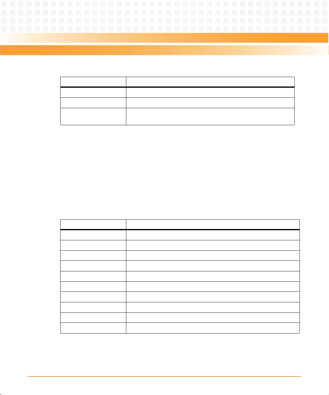
Operation
Table 5-30 Save & Exit Menu (continued)
Field Description
Save as User Defaults Save the changes done so far as user defaults.
Restore User Defaults Restore the user defaults to all the setup options.
Boot Override Overrides the boot orders in Boot menu. So you can select the device
which you want to boot.
5.5 POST Codes
5.5.1 Status Code Ranges
Table 5-31 Status Code Ranges
Status Code Range Description
0x01 - 0x0F SEC Status Codes & Errors.
0x10 - 0x2F PEI execution up to and including memory detection.
0x30 - 0x4F PEI execution after memory detection.
92
0x50 - 0x5F PEI errors.
0x60 - 0xCF DXE execution up to BDS.
0xD0 - 0xDF DXE errors.
0xE0 - 0xE8 S3 Resume (PEI).
0xE9 - 0xEF S3 Resume errors (PEI).
0xF0 - 0xF8 Recovery (PEI).
0xF9 - 0xFF Recovery errors (PEI).
MITX-430/MITX-440-DVI-2E Installation and Use Guide (6806800K37B)
Page 93

Operation
5.5.2 Standard Status Codes
5.5.2.1 SEC Status Codes
Table 5-32 SEC Status Codes
Status Code Description
0x0 Unused.
Progress Codes
0x1 Power on. Reset type detection (soft/hard).
0x2 AP initialization before microcode loading.
0x3 North Bridge initialization before microcode loading.
0x4 South Bridge initialization before microcode loading.
0x5 OEM initialization before microcode loading.
0x6 Microcode loading.
0x7 AP initialization after microcode loading.
0x8 North Bridge initialization after microcode loading.
0x9 South Bridge initialization after microcode loading.
0xA OEM initialization after microcode loading.
0xB Cache initialization.
SEC Error Codes
0xC - 0xD Reserved for future AMI SEC error codes.
0xE Microcode not found.
0xF Microcode not loaded.
MITX-430/MITX-440-DVI-2E Installation and Use Guide (6806800K37B)
93
Page 94

Operation
5.5.2.2 PEI Status Codes
Table 5-33 PEI Status Codes
Status Code Description
Progress Codes
0x10 PEI Core is started.
0x11 Pre-memory CPU initialization is started.
0x12 CPU pre-memory initialization (CPU module specific).
0x13 CPU pre-memory initialization (CPU module specific).
0x14 CPU pre-memory initialization (CPU module specific).
0x15 Pre-memory North Bridge initialization is started.
0x16 Pre-memory North Bridge initialization (North Bridge module
0x17 Pre-Memory North Bridge initialization (North Bridge module
0x18 Pre-Memory North Bridge initialization (North Bridge module
0x19 Pre-memory South Bridge initialization is started.
0x1A Pre-memory South Bridge initialization (South Bridge module
0x1B Pre-memory South Bridge initialization (South Bridge module
specific).
specific).
specific).
specific).
specific).
94
0x1C Pre-memory South Bridge initialization (South Bridge module
specific).
0x1D - 0x2A OEM pre-memory initialization codes.
0x2B Memory initialization. Serial Presence Detect (SPD) data reading.
0x2C Memory initialization. Memory presence detection.
0x2D Memory initialization. Programming memory timing information.
0x2E Memory initialization. Configuring memory.
0x2F Memory initialization (other).
MITX-430/MITX-440-DVI-2E Installation and Use Guide (6806800K37B)
Page 95

Operation
Table 5-33 PEI Status Codes (continued)
Status Code Description
0x30 Reserved for ASL, see Table 5-38 on page 102.
0x31 Memory Installed.
0x32 CPU post-memory initialization is started.
0x33 CPU post-memory initialization. Cache initialization.
0x34 CPU post-memory initialization. Application Processor(s) (AP)
initialization.
0x35 CPU post-memory initialization. Boot Strap Processor (BSP) selection.
0x36 CPU post-memory initialization. System Management Mode (SMM)
initialization.
0x37 Post-Memory North Bridge initialization is started.
0x38 Post-Memory North Bridge initialization (North Bridge module
specific).
0x39 Post-Memory North Bridge initialization (North Bridge module
specific).
0x3A Post-Memory North Bridge initialization (North Bridge module
specific).
0x3B Post-Memory South Bridge initialization is started.
0x3C Post-Memory South Bridge initialization (South Bridge module
specific).
0x3D Post-Memory South Bridge initialization (South Bridge module
specific).
0x3E Post-Memory South Bridge initialization (South Bridge module
specific).
0x3F OEM post memory initialization codes.
0x4F DXE IPL is started.
PEI Error Codes
0x50 Memory initialization error. Invalid memory type or incompatible
memory speed.
0x51 Memory initialization error. SPD reading has failed.
0x52 Memory initialization error. Invalid memory size or memory modules
do not match.
MITX-430/MITX-440-DVI-2E Installation and Use Guide (6806800K37B)
95
Page 96

Operation
Table 5-33 PEI Status Codes (continued)
Status Code Description
0x53 Memory initialization error. No usable memory detected.
0x54 Unspecified memory initialization error.
0x55 Memory not installed.
0x56 Invalid CPU type or Speed.
0x57 CPU mismatch.
0x58 CPU self test failed or possible CPU cache error.
0x59 CPU micro-code is not found or micro-code update has failed.
0x5A Internal CPU error.
0x5B Reset PPI is not available.
0x5C-0x5F Reserved for future AMI error codes.
S3 Resume Progress Codes
0xE0 S3 resume is started (S3 resume PPI is called by the DXE IPL).
0xE1 S3 boot script execution.
0xE2 Video repost.
0xE3 OS S3 wake vector call.
96
0xE4-0xE7 Reserved for future AMI progress codes.
0xE0 S3 resume is started (S3 resume PPI is called by the DXE IPL).
S3 Resume Error Codes
0xE8 S3 resume failed in PEI.
0xE9 S3 resume PPI not found.
0xEA S3 resume boot script error.
0xEB S3 OS wake error.
0xEC-0xEF Reserved for future AMI error codes.
Recovery Progress Codes
0xF0 Recovery condition triggered by firmware (Auto recovery).
0xF1 Recovery condition triggered by user (Forced recovery).
0xF2 Recovery process started.
MITX-430/MITX-440-DVI-2E Installation and Use Guide (6806800K37B)
Page 97
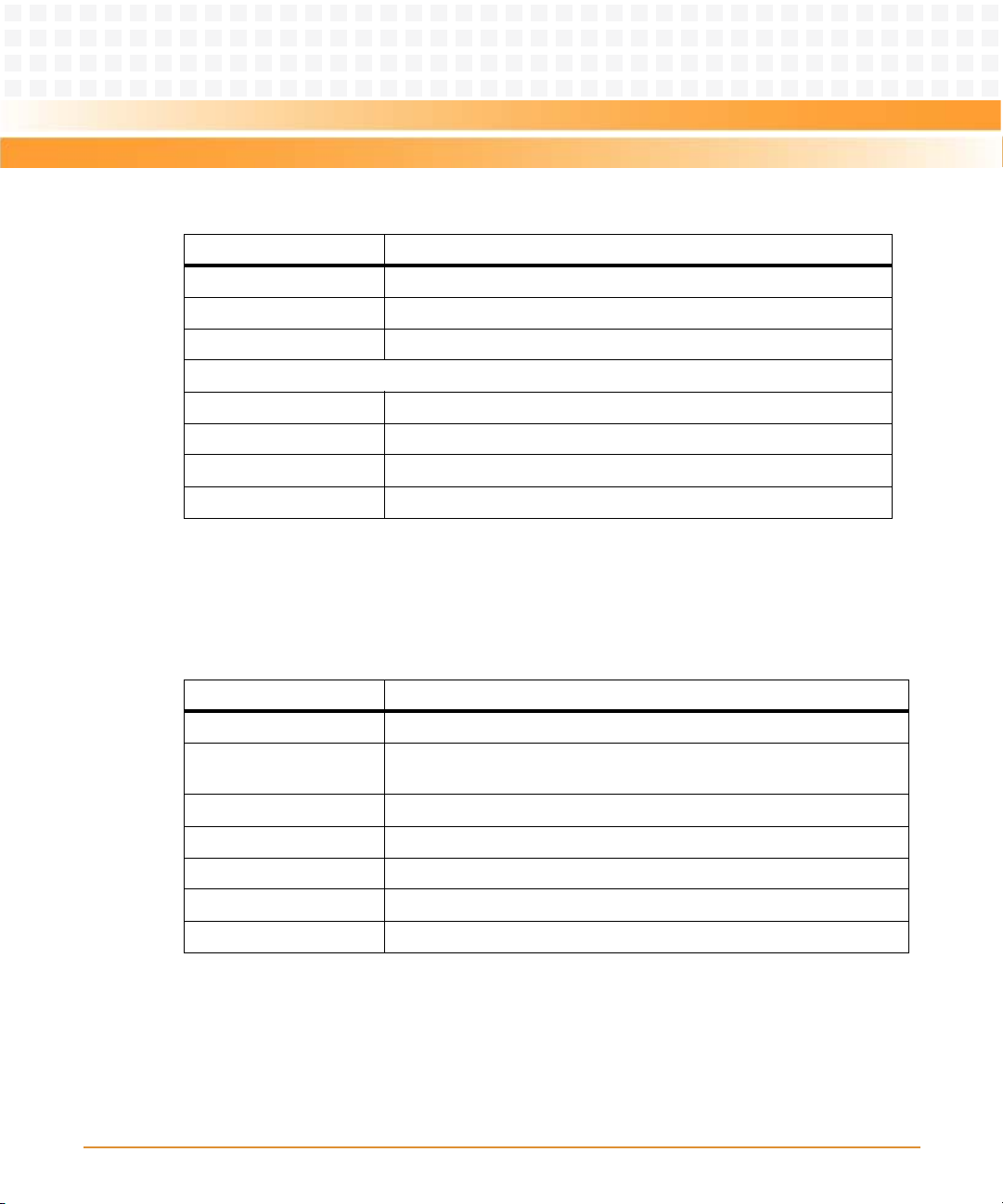
Operation
Table 5-33 PEI Status Codes (continued)
Status Code Description
0xF3 Recovery firmware image found.
0xF4 Recovery firmware image loaded.
0xF5 - 0xF7 Reserved for future AMI progress codes.
Recovery Error Codes
0xF8 Recovery PPI is not available.
0xF9 Recovery capsule is not found.
0xFA Invalid recovery capsule.
0xFB - 0xFF Reserved for future AMI error codes.
5.5.2.3 PEI Beep Codes
Table 5-34 PEI Beep Codes
# of Beeps Description
1Memory not Installed.
1 Memory was installed t wice (InstallPeiMemory routine in PEI Core called
twice).
3 DXEIPL was not found.
3 DXE core firmware volume was not found.
7 Reset PPI is not available.
4 Recovery failed.
4 S3 resume failed.
MITX-430/MITX-440-DVI-2E Installation and Use Guide (6806800K37B)
97
Page 98

Operation
5.5.2.4 DXE Status Codes
Table 5-35 DXE Status Codes
Status Code Description
0x60 DXE Core is started.
0x61 NVRAM initialization.
0x62 Installation of the South Bridge Runtime Services.
0x63 CPU DXE initialization is started.
0x64 CPU DXE initialization (CPU module specific).
0x65 CPU DXE initialization (CPU module specific).
0x66 CPU DXE initialization (CPU module specific).
0x67 CPU DXE initialization (CPU module specific).
0x68 PCI host bridge initialization.
0x69 North Bridge DXE initialization is started.
0x6A North Bridge DXE SMM initialization is started.
0x6B North Bridge DXE initialization (North Bridge module specific).
98
0x6C North Bridge DXE initialization (North Bridge module specific).
0x6D North Bridge DXE initialization (North Bridge module specific).
0x6E North Bridge DXE initialization (North Bridge module specific).
0x6F North Bridge DXE initialization (North Bridge module specific).
0x70 South Bridge DXE initialization is started.
0x71 South Bridge DXE SMM initialization is started.
0x72 South Bridge devices initialization.
0x73 South Bridge DXE initialization (South Bridge module specific).
0x74 South Bridge DXE initialization (South Bridge module specific).
0x75 South Bridge DXE initialization (South Bridge module specific).
0x76 South Bridge DXE initialization (South Bridge module specific).
0x77 South Bridge DXE initialization (South Bridge module specific).
MITX-430/MITX-440-DVI-2E Installation and Use Guide (6806800K37B)
Page 99

Operation
Table 5-35 DXE Status Codes (continued)
Status Code Description
0x78 ACPI module initialization.
0x79 CSM initialization.
0x7A Reserved for future AMI DXE codes.
0x80 OEM DXE initialization codes.
0x90 Boot Device Selection (BDS) phase is started.
0x91 Driver connecting is started.
0x92 PCI Bus initialization is started.
0x93 PCI Bus hot plug controller initialization.
0x94 PCI Bus enumeration.
0x95 PCI Bus request resources.
0x96 PCI Bus assign resources.
0x97 Console output devices connect.
0x98 Console input devices connect.
0x99 Super IO Initialization.
0x9A USB initialization is started.
0x9B USB reset.
0x9C USB detect.
0x9D USB enable.
0x9E Reserved for future AMI codes.
0xA0 Reserved for ASL. See Table 5-38 on page 102.
0xA1 IDE initialization is started.
0xA2 IDE reset.
0xA3 IDE detect.
0xA4 IDE enable.
0xA5 SCSI initialization is started.
0xA6 SCSI reset.
0xA7 SCSI detect.
MITX-430/MITX-440-DVI-2E Installation and Use Guide (6806800K37B)
99
Page 100

Operation
Table 5-35 DXE Status Codes (continued)
Status Code Description
0xA8 SCSI enable.
0xA9 Setup verifying password.
0xAA Reserved for ASL. See Table 5-38 on page 102.
0xAB Start of setup.
0xAC Setup input wait.
0xAD Ready to boot event.
0xAE Legacy boot event.
0xAF Exit boot services event.
0xB0 Runtime set virtual address MAP begin.
0xB1 Runtime set virtual address MAP end.
0xB2 Legacy option ROM initialization.
0xB3 System reset.
0xB4 USB hot plug.
0xB5 PCI bus hot plug.
0xB6 Clean-up of NVRAM.
100
0xB7 Configuration reset (reset of NVRAM settings).
0xB8 Reserved for future AMI codes.
0xC0 OEM BDS initialization codes.
DXE Error Codes
0xD0 CPU initialization error.
0xD1 North Bridge initialization error.
0xD2 South Bridge initialization error.
0xD3 Some of the Architectural Protocols are not available.
0xD4 PCI resource allocation error. Out of resources.
0xD5 No space for legacy option ROM.
0xD6 No console output devices are found.
0xD7 No console input devices are found.
MITX-430/MITX-440-DVI-2E Installation and Use Guide (6806800K37B)
 Loading...