

Emerson Mini Maestro DCD60x3/6, Mini Maestro DCD60x10/20, Mini Maestro DCD60x14/28, Mini Maestro DCD60x7/14 User Manual
Page 1

User Guide
Variable Speed Drive for
Permanent-magnet DC
Servo-motors
Part Number: 0470-0009-05
Issue: 5
www.controltechniques.com
Mini Maestro
Page 2

Safety Information
Persons supervising and performing the electrical installation or maintenance of a
Drive and/or its external Option Unit must be suitably qualified and competent in
these duties. They should be given the opportunity to study and if necessary to
discuss this User Guide before work is started.
The Drive is intended for operation from a nominal 60V DC supply. It is the installer’s
responsibility to ensure that this supply is safely isolated from dangerous mains
supply voltages, and correctly protected by fuses.
The Stop function of the Drive does not remove voltages from the terminals of the
Drive and external Option Unit. Mains supplies should be removed before any
servicing work is performed.
The installation instructions should be adhered to. Any questions or doubt should be
referred to the supplier of the equipment. It is the responsibility of the owner or user
to ensure that the installation of the Drive and external Option Unit, and the way in
which they are operated and maintained complies with the requirements of the
Health and Safety at Work Act in the United Kingdom and applicable legislation and
regulations and codes of practice in the UK or elsewhere.
The Drive may start automatically when power is applied. All necessary precautions
must be taken to avoid injury to personnel or damage to equipment as the result of
unexpected application of power.
The enable input of the Drive should not be relied upon to ensure safety of
personnel. If a safety hazard could exist from unexpected starting of the Drive, an
interlock should be installed to prevent the motor being inadvertently started.
General Information
The manufacturer accepts no liability for any consequences resulting from
inappropriate, negligent or incorrect installation or adjustment of the optional
operating parameters of the equipment or from mismatching the Drive with the
motor.
The contents of this User Guide are believed to be correct at the time of printing. In
the interests of a commitment to a policy of continuous development and
improvement, the manufacturer reserves the right to change the specification of the
product or its performance, or the contents of the User Guide, without notice.
All rights reserved. No part of this User Guide may be reproduced or transmitted in
any form or by any means, electrical or mechanical including photocopying,
recording or by any information storage or retrieval system, without permission in
writing from the publisher.
Copyright © June 2007 Control Techniques Drives Ltd
Issue Code: 5
Page 3

Mini Maestro User Guide 3
Issue Number: 5 www.controltechniques.com
Contents
1 Data .................................................................................4
2 Mechanical Installation ..................................................6
2.1 Dimensions of the drive ...........................................................................6
2.2 Mounting location ....................................................................................6
2.3 Choke (optional) ......................................................................................9
3 Electrical Installation ...................................................11
3.1 Connections ..........................................................................................11
3.2 Grounding ..............................................................................................13
3.3 External power supply ...........................................................................13
3.4 Motor connections .................................................................................16
3.5 Signal connections ................................................................................17
4 Setting up the drive ......................................................18
4.1 Adjusting the potentiometers .................................................................18
4.2 Mounted components ............................................................................19
4.3 Making adjustments to the drive ............................................................20
4.4 Motor phasing ........................................................................................23
4.5 Dynamic calibration ...............................................................................23
5 Diagnostics ...................................................................27
5.1 LED indicators .......................................................................................27
5.2 Fault finding ...........................................................................................27
6 Accessories ..................................................................28
Page 4
4 Mini Maestro User Guide
www.controltechniques.com Issue Number: 5
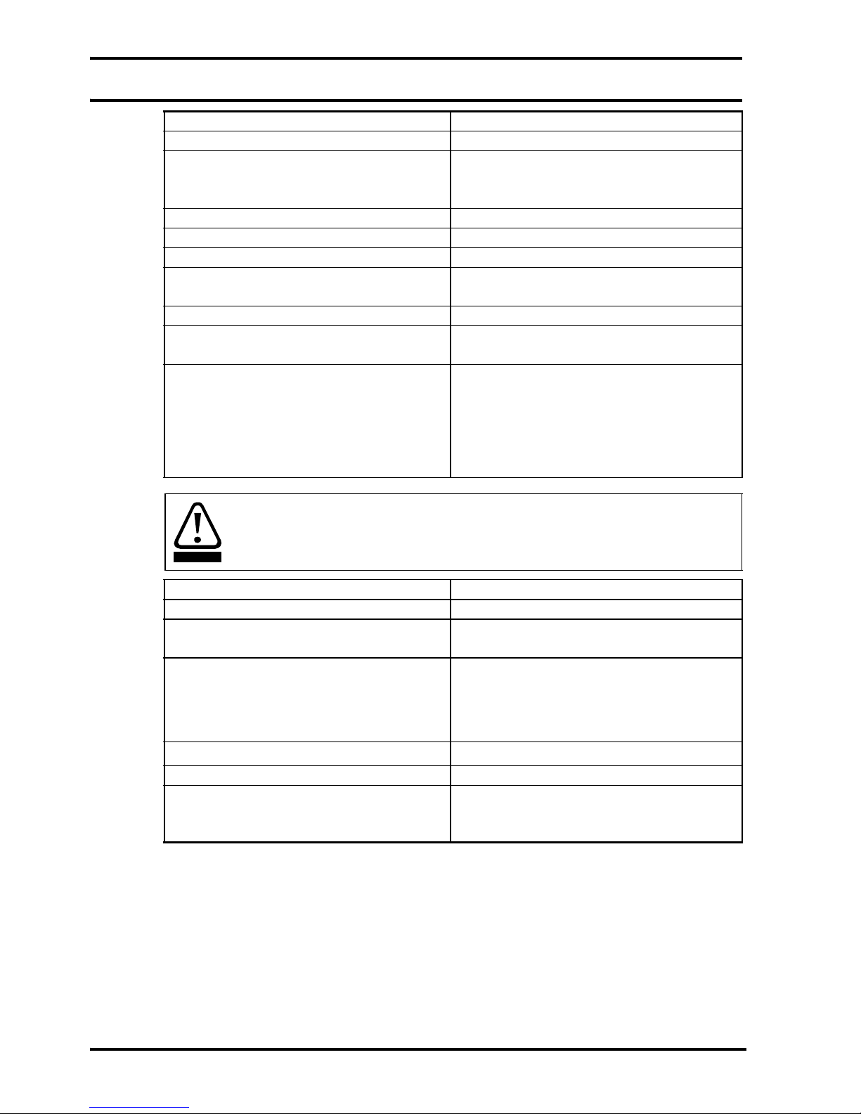
1Data
Analog speed reference input ±10V (33kΩ input impedance)
Analog current reference input ±10V 22kΩ (TPRC)
Enable signal Minimum 10V
Maximum 30V
20kΩ input impedance
Error amplifier temperature drift ±25 µV / °C
Error amplifier offset Offset at 25°C ±100µV
Tachogenerator feedback control range 1 to 5000 RPM
Minimum tachogenerator signal at
maximum speed
5V
Armature feedback control range 150 ~ 3000 RPM
Ambient temperature Operating temperature range –10°C (50°F)
to +45°C (113°F)
D C s u p p l y : B a t t e r y
Nominal
Rectified AC supply
Minimum 24V
Maximum 72V
60V
Minimum 20V
Maximum 80V
Maximum ripple 2V peak to peak
Reference voltages ±10V 3mA maximum
Monitor motor current ±8V
Monitor motor requested current
(TPRC)
±10V
Power cables
2.5 mm
2
(AWG 14) for DCD60x10/20 and
DCD60x14/28 models
1.5 mm
2
(AWG 16) for DCD60x3/6 and
DCD60x7/14 models
Signal wiring
0.5mm
2
(AWG 20)
Current tolerance ±10%
Protection Overtemperature on heatsink 100°C
Undervoltage 20V
Overvoltage 80V
The supply terminals are not isolated from the control terminals.
The supply must either be isolated, or have its negative pole grounded.
WARNING
Page 5

Mini Maestro User Guide 5
Issue Number: 5 www.controltechniques.com
Output ratings
Model Nominal current Peak current
DCD60x3/6 1 to 3 A 6A for 2 sec.
DCD60x7/14 2 to 7 A 14A for 2 sec.
DCD60x10/20 3 to 10 A 20A for 2 sec.
DCD60x14/28 5 to 14 A 28A for 2 sec.
The peak current can be adjusted from 50% to 100% using the RIP resistor mounted on
SK1.
NOTE
The nominal current can be adjusted in the range shown using the RIN resistor mounted
on SK1.
NOTE
Page 6
6 Mini Maestro User Guide
www.controltechniques.com Issue Number: 5
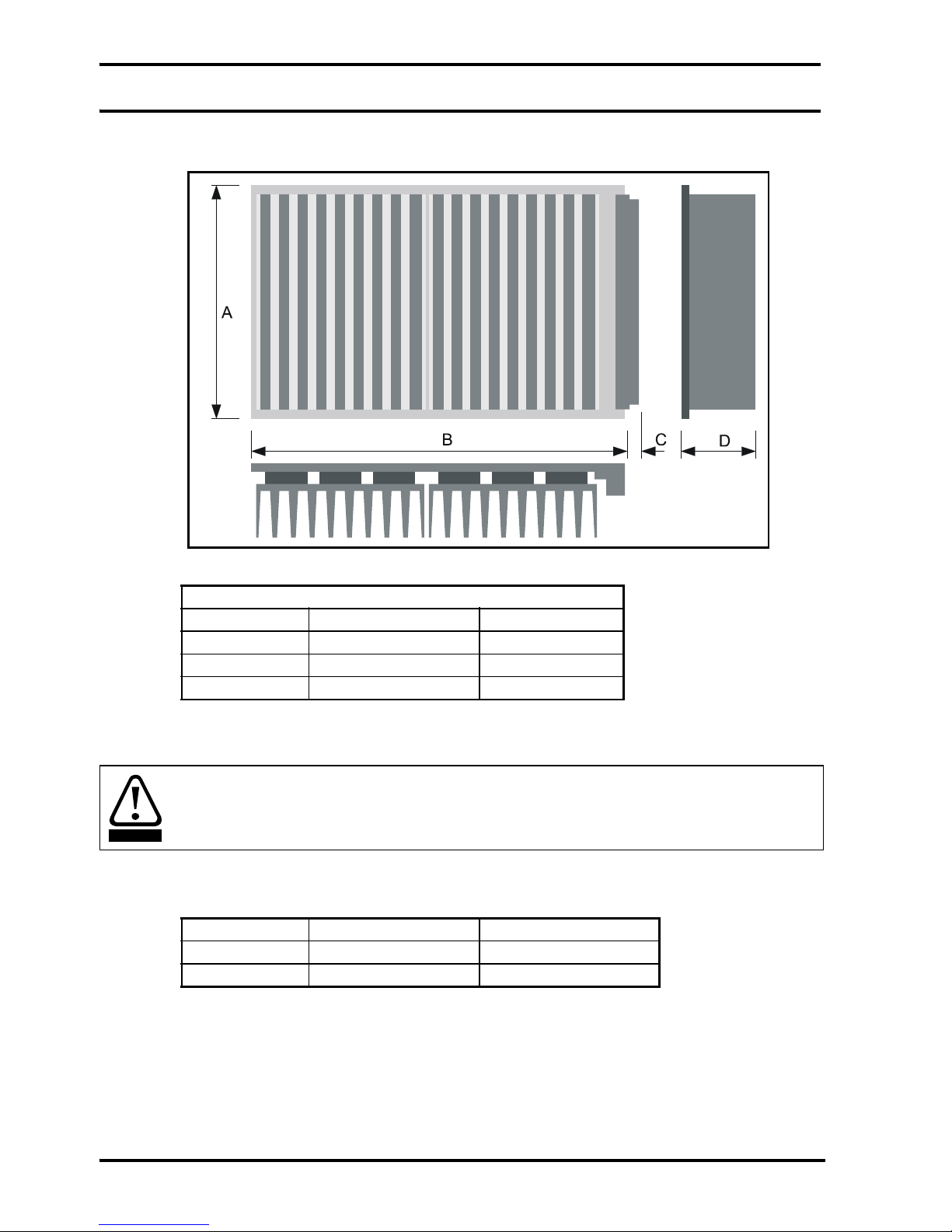
2 Mechanical Installation
2.1 Dimensions of the drive
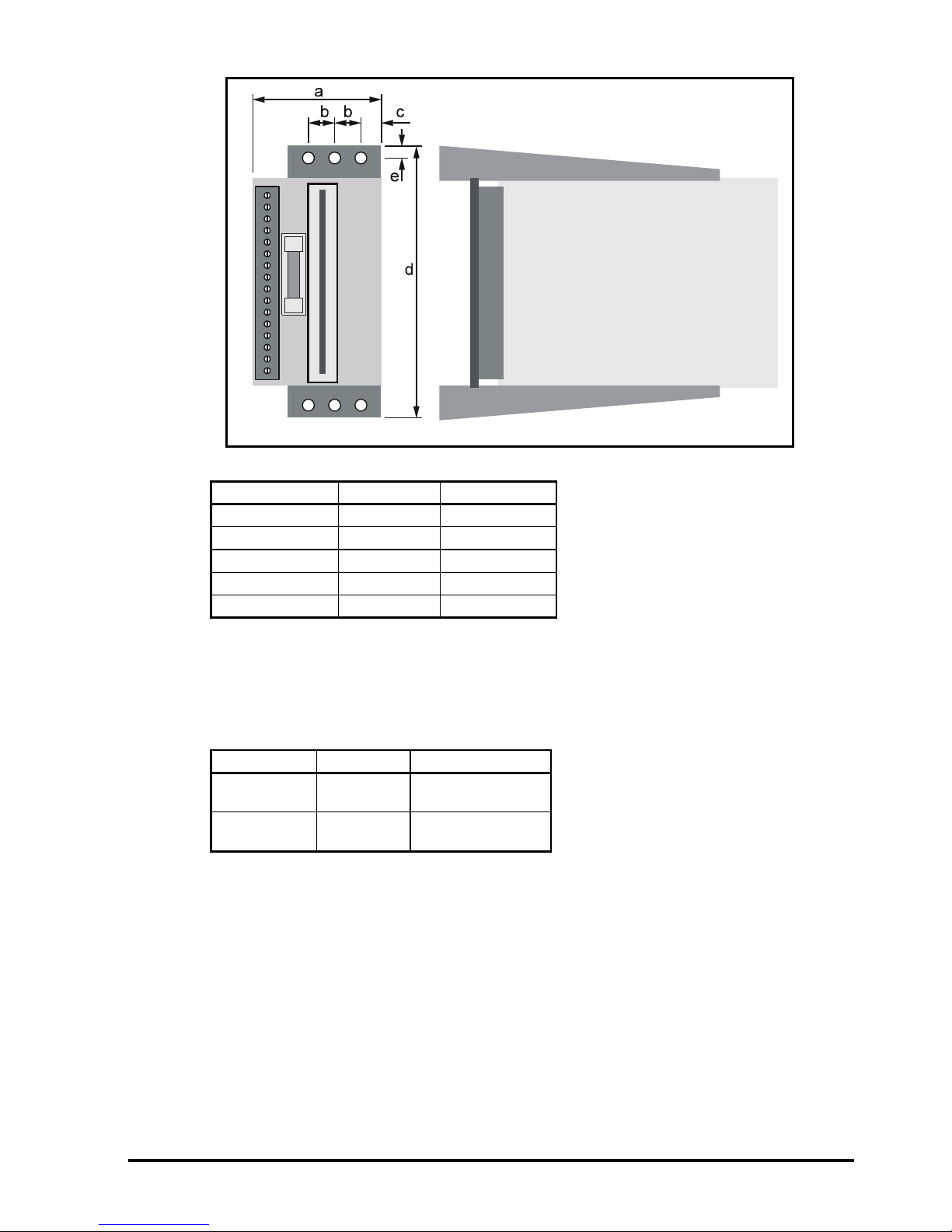
Figure 2-1 Overall dimensions of the drive
2.2 Mounting location
The drive is contained on a Eurocard circuit board having a 64-pin DIN connector. Two
installation kits allow for installation as follows:
The ingress protection rating of the drive is IP00. When greater protection is required,
install the drive in a cabinet.
Choose a location that is free from excessive dust, corrosive vapours, gases and all
liquids, including condensation of atmospheric moisture.
Dimensions of the drive
A 100mm 3.937in
B 160mm 6.300in
C 8mm 0.315in
D 41mm 1.614in
Electric shock risk
The heatsink on the drive is LIVE. Switch off the supply and wait at least 10 seconds
before touching any part of the drive.
WARNING
Installation kit Part number Installation
3MB 7500 - 0009 Standard 19 inch rack
2MH 7500 - 0008 Panel mounting
Page 7
Mini Maestro User Guide 7
Issue Number: 5 www.controltechniques.com
If condensation is likely to occur when the drive is not in use, install an anticondensation heater. This heater must be switched off when the drive is in use;
automatic switching is recommended.
Install the drive so that the heatsink fins are vertical for best flow of cooling air.
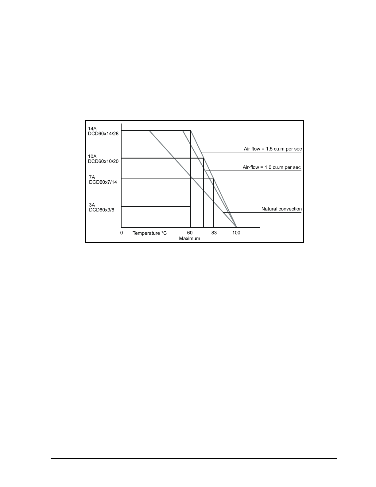
Observe the requirements for ambient temperature if the drive is to be mounted directly
above any heat generating equipment (such as another drive). When the ambient
temperature exceeds 50°C (120°F), the output power of the drive must be derated. The
drive has over-temperature protection which trips the drive when the heatsink reaches
100°C (212°F).
Figure 2-2 Derating the maximum output current with temperature
If the drive is to be installed directly beneath other equipment (such as another Variable
Speed drive), ensure the drive does not cause the ambient temperature requirements of
the equipment to be exceeded.
Leave adequate clearance around the drive to allow unimpeded airflow to the heatsink.
For model DCD60x14/28, apply forced cooling using a fan and cabinet of adequate
size.
The total power dissipated as heat from a drive, choke, transformer and heatsink is 10%
to 15% of the motor power.
Page 8
8 Mini Maestro User Guide
www.controltechniques.com Issue Number: 5
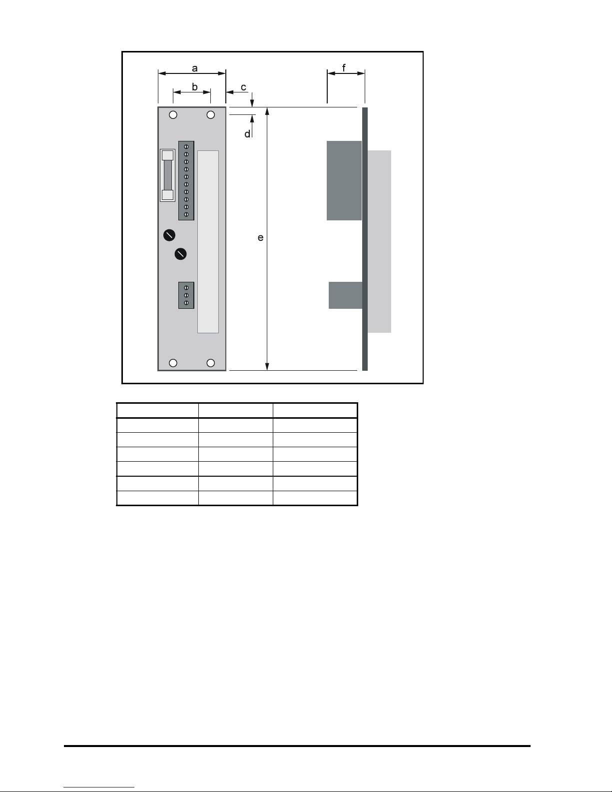
Figure 2-3 Dimensions of 3MB rack-mount installation kit
Dimension mm in
a 40 1.575
b 26 1.024
c 7 0.276
d 8 0.315
e 130 5.118
f 20 0.787
Page 9
Mini Maestro User Guide 9
Issue Number: 5 www.controltechniques.com
Figure 2-4 Dimensions of 2MH panel-mounting installation kit
2.3 Choke (optional)
When a motor has an inductance less than 1mH, a choke must be connected between
the motor and drive, and as close as possible to the drive. Refer to Figure 2-5 for
dimensions of the choke.
Dimension mm in
a 66 2.598
b 15 0.591
c 8 0.315
d 132 5.197
e 5 0.197
Model Choke Choke rating
DCD60x3/6
DCD60x7/14
L11 0.7mH, 8A
DCD60x10/20
DCD60x14/28
L12 1mH, 14A
Page 10

10 Mini Maestro User Guide
www.controltechniques.com Issue Number: 5
Figure 2-5 Dimensions of the L11 and L12 chokes
Dimension L11 L12
mm in mm in
a 56 2.205 75 2.953
b 12 0.472 87 3.425
c 64 2.520 7 0.276
d 56 2.205 75 2.953
e 64 2.520 100 3.937
f 6 0.236 8 0.315
g 52 2.047 44 1.732
h 40 1.575 44 1.732
j110.433
k 46 1.811 60 2.362
Hole diameter 4 0.157 4 0.157
Page 11

Mini Maestro User Guide 11
Issue Number: 5 www.controltechniques.com
3 Electrical Installation
3.1 Connections
Installation kits
Figure 3-1 Signal and power connections on the 3MB installation kit
Figure 3-2 Signal and power connections on the 2MH installation kit
Page 12

12 Mini Maestro User Guide
www.controltechniques.com Issue Number: 5
Figure 3-3 Locations of the signal and power connections on the installation kits
Edge connector of the drive
When an installation kit is used, the functions of the connections on the edge connector
do not need to be known. The connections are as follows:
ing
1
18
Pin number Function
1 Signal common
2 Protection enable
3TPRC
4 –10V, 3mA supply
5 +10V, 3mA supply
6 Speed reference input [non inverting]
7 Drive enable
8 Signal common
9 Tachogenerator input
10 Speed reference input [inverting]
11 I
mot
Analog signal proportional to the effective current in the motor
14, 15, 16, 17 +DC supply input
19, 20, 21, 22 –DC supply input
24, 25, 26, 27 Motor output + [M1]
29, 30, 31, 32 Motor output – [M2]
12, 13, 18, 23 Do not use
The signal common terminals are at the same potential as the -DC supply input terminals
CAUT ION
Page 13

Mini Maestro User Guide 13
Issue Number: 5 www.controltechniques.com
3.2 Grounding
To avoid intermittent tripping of the drive, use a single ground point for the supply and
signal circuits. A grounding bar of appropriate size can be used. This must be mounted
on insulated supports as close as possible to the drive and connected to the chassis
ground using cable of 10mm
2
to 20mm2. The shortest possible wiring should be used.
The connection to the chassis terminal of the enclosure must be adequately sized.
If in doubt, consult the supplier of the drive.
Figure 3-4 Ground connections
3.3 External power supply
A single external power supply may be used to supply a number of drives.
Peak motor current less than 15A
Use a single-phase or three-phase AC supply.
Peak motor current 15A or greater
Use a three-phase AC supply.
Signal cables and supply cables must be segregated and wired through different
trunking
NOTE
Page 14

14 Mini Maestro User Guide
www.controltechniques.com Issue Number: 5
Figure 3-5 Single-phase and three-phase power supply circuits
Transformer ratings
Power rating
Use the following equation:
Pt = {(Paz x 1.7) + 80} x 1.73 ÷ √(n + 2)
Where:
Paz = (Vm1 x Cm1) + (Vm2 x Cm2) + ...
Vm = Motor speed in radians per second (RPM ÷ 9.5)
Cm = Nominal torque in Nm
1.73 ÷ √(n + 2) Empirical conversion factor for drives connected in parallel
Secondary voltage
Select the required secondary voltage, as follows:
With no load: V2 ≅ V1 x 1.4
With full load: V2 ≅ V1 x 1.2
DC supply to the drive Secondary voltage VRMS
63 45
21 15
80 56
Page 15

Mini Maestro User Guide 15
Issue Number: 5 www.controltechniques.com
Reservoir capacitors
Use the following equation to calculate the total required value of reservoir capacitance:
C = (Pt ÷ V2) x 2000 µF
The factor 2000 allows for regeneration current during braking.
The factor can be reduced to 1000 when all of the following conditions apply:
V2 = 24V to 45V
Maximum motor speed = 1500 RPM
Three-phase AC supply is used
System inertia is less than the motor inertia
.Discharge resistor
The discharge resistor ensures the reservoir capacitors are discharged in 10 seconds
when the AC supply is disconnected from the drive.
Use the following equation to calculate the required value: R = 20 ÷ C
Use the following equation to calculate the power rating: P = [V2]
2
÷ R
AC supply fuses
Delayed action fuses should be connected in the primary and secondary circuits of the
transformer.
Use the following equations to calculate the ratings of the fuses:
DC supply fuses
A 12.5A fast-action fuse is fitted in the fuse holder on the panel of the installation kit.
This protects the DC supply to the drive. If necessary, replace this fuse with a 16A fastaction fuse. Refer to the following table:
If the green drive normal LED on the drive becomes unlit (even temporarily) when the
motor is being decelerated, this indicates overvoltage protection is occurring. To prevent
this occurrence, increase the value of reservoir capacitance
NOTE
Correct fuse protection must be used to avoid fire risk.
WARNING
Number of phases Primary fuses Secondary fuses
1 1.3 x Pt ÷ (VAC + 1) Frm 1.6 x Pt ÷ V1 Fsm
3 0.75 x Pt ÷ (VAC + 1) Frt Pt ÷ V1 Fst
DCD60x3/6 DCD60x7/14 DCD60x10/20 DCD60x14/28
12.5A 12.5A 16A 16A
Page 16

16 Mini Maestro User Guide
www.controltechniques.com Issue Number: 5
3.4 Motor connections
Normally the motor should be connected directly to the connector on the installation kit.
When any of the following conditions apply, a choke should be connected to each drive
output as shown in Figure 3-6.
• The motor inductance is less than 1mH
• During emergencies, the user short-circuits the motor connections
• High frequency switching noise is troublesome
• The motor overheats (irrespective of motor inductance)
Figure 3-6 Motor and choke connections
The two cables between the drive and the choke are a source of noise. The cables
should be kept as short as possible (300mm is recommended).
Terminal 3 of the choke should be connected to the + terminal of the motor.
Terminal 5 should be connected to the – terminal on the motor.
Terminal 4 should be connected to the grounding bar (only applies to L12).
Page 17

Mini Maestro User Guide 17
Issue Number: 5 www.controltechniques.com
3.5 Signal connections
Table 3.1 Signal connections common to both mounting kits
DC supply connections for 3MB
DC supply connections for 2MH
Motor connections for 3MB
Motor connections for 2MH
Signal cables and power cables must be segregated and wired through different
trunking.
Terminal
No.
Description I/O Notes
1
I
MOT
O
Analog signal proportional to the effective current in the motor.
Output signal ± 8V at maximum current.
2 Protection active O
NPN open-collector output 100mA, 47V. Use this to enable external
protection devices when the drive trips.
3 TPRC I/O
Analog signal proportional to the value of the requested current.
Signal range ±10V. When at ±10V the drive generates peak current.
When used as an input, and the same voltage range is applied, the drive
becomes a current amplifier using the applied voltage as current
reference.
40V
Signal common
5 -10V reference O 3mA max
6 +10V reference O 3mA max
7 Enable I
When a 10V DC to 30V DC signal is applied to this terminal, the drive is
enabled. When the signal is discontinued, the drive is disabled (0V).
Input impedance = 47kW
8
Speed reference
(non-inverting input)
I
When a differential signal from the external controller is not available,
connect terminal 10 to terminal 9.
90V
Signal common.
10
Speed reference
(inverting input)
I
The speed reference signal input is a differential input to minimize noise
problems.
11
Tac ho
(non-inverting input)
I Tachogenerator signal.
12
Tac ho
(inverting input)
I Tachogenerator signal.
NOTE
13 +DC I
14 -DC I
13 + 14 +DC I
15 + 16 -DC I
15 Motor M1 O Motor positive
16 Not used
17 Motor M2 O Motor negative
17 Motor M1 O Motor positive
18 Motor M2 O Motor negative
Page 18

18 Mini Maestro User Guide
www.controltechniques.com Issue Number: 5
4 Setting up the drive
Set up the drive by adjusting potentiometers and replacing specific capacitors and fixed
resistors. These components are fitted to socket SK1. If a drive is replaced, the socket
can be transferred to the replacement drive in order to keep the settings.
4.1 Adjusting the potentiometers
Five potentiometers are labelled as follows:
RAMP
DERIVATIVE
PROPORTIONAL
ZERO OFFSET
MAX SPEED
Figure 4-1 Locations of the potentiometers on the drive
RAMP potentiometer
Adjust the potentiometer to increase or decrease the time from 0 second to 2 seconds
for the motor to reach maximum speed (with a 10V speed reference signal). To disable
ramps set the potentiometer at the fully anti-clockwise position.
DERIVATIVE potentiometer
Turn the potentiometer clockwise to reduce the amount of overshoot in the system
response by increasing the derivative gain of the PID amplifier.
PROPORTIONAL potentiometer
Turn the potentiometer clockwise to increase the proportional gain of the PID amplifier.
ZERO REF potentiometer
Adjust this potentiometer to cancel any offset in the external speed reference signal.
MAX SPEED potentiometer
Turn the potentiometer anti-clockwise to reduce the maximum motor speed to 50%.
Turn the potentiometer clockwise to increase the maximum motor speed to 120%.
Drive status indicator LED
s
Te s t po i nt s
Potentiometers
0V
Page 19

Mini Maestro User Guide 19
Issue Number: 5 www.controltechniques.com
4.2 Mounted components
Figure 4-2 Locations of the mounted components on the drive
The following resistors and capacitors are mounted on socket SK1:
RIP resistor
Reduces the peak current to the required value.
RAI resistor
Compensates for the voltage drop due to internal resistance of the motor.
RIN resistor
Reduces the nominal current to the required value.
RKW.CRA resistor
Adjusts the drive for armature voltage speed feedback.
DER capacitor
Adjusts derivative gain.
INT capacitor
Adjusts integral gain.
JUMP.CRA jumper
Adjusts the response of the system when the drive is in armature feedback mode.
RT resistor
Normalizes the tachogenerator input signal and adapts the drive to the voltage
constant of the tachogenerator.
Most applications do not require DER or INT capacitors to be used. When an
application does require these capacitors, the recommended value is between 0.1mF
and 5mF.
NOTE
Page 20

20 Mini Maestro User Guide
www.controltechniques.com Issue Number: 5
4.3 Making adjustments to the drive
Zero speed offset
ZERO REF potentiometer
1. Connect the non-inverting input of the speed reference signal to terminal 9 and the
inverting input to terminal 10.
2. Set the speed reference signal for zero speed.
3. Apply +10V to +30V to terminal 7 Drive Enable.
4. Connect a digital multimeter to pins 11 and 12.
5. Enable the drive and adjust the ZERO REF potentiometer to reduce the multimeter
reading to not more than 1mV.
6. Restore the original wiring.
Maximum speed
RT resistor
Use the following equation to calculate the value of the RT resistor:
RT = 400 [(Vm x Ke
tacho
) - 5Ω]
Where:
Vm = Maximum speed of motor in RPM ÷
1000
Ke
tacho
= Tachogenerator voltage constant (voltage output at 1000 RPM) and in
general Ke
tacho
= V* 1000 / RPM
Resistor ratings:
Power: 0.25W
Tolerance: +20%.
Example
Max required speed = 3000 RPM ∴Vm = 3
Tachogenerator output = 7V at 1000 RPM ∴ Ke
tacho
= 7
Calculate:
RT = 400 [ (3 x 7) - 5Ω ] = 6.4kΩ
The nearest suitable value is 6.8kΩ.
A 10kΩ RT resistor is fitted as standard. This value is suitable for tachogenerator
voltage constant, Ke
tacho
= 10 and maximum motor speed = 3000 rpm.
NOTE
If the calculated value of RT is zero, fit a jumper instead of a resistor
If the calculated value is negative, the tachogenerator must be changed for one with a
greater value of Ke
tacho
in order for the motor to reach the required speed.
NOTE
Page 21

Mini Maestro User Guide 21
Issue Number: 5 www.controltechniques.com
Adjusting the nominal current
When the nominal current rating of the motor is less than the nominal current of the
drive, it is possible to reduce the maximum value of current produced by the drive by
fitting a RIN resistor. Refer to the following table:
The following equation is used to calculate the value of the RIN resistor:
Where:
I
NOM
= nominal desired current value
I
PEAK
= Drive peak current value
Adjusting speed for operation in armature feedback mode
JUMP.CRA jumper
RKW.CRA resistor
RAI resistor
Armature feedback mode can be used when a tachogenerator is not fitted to the motor.
Speed control is then less precise.
Speed is controlled using the motor voltage as feedback.
Voltage drop due to motor resistance can be compensated by adjusting the value of the
RAI resistor.
1. Connect jumper JUMP.CRA to enable operation with armature feedback.
2. Use the following equation to calculate the correct value of RKW resistor:
RKW = 0.260 x Vm x Ke
motor
Where:
Vm = Maximum speed in RPM
Ke
motor
= Motor voltage constant (voltage at 1000 RPM)
Calculating the value of the RAI resistor can be difficult since it is a function of the
following:
• Motor characteristics. (eg. armature resistance and temperature).
• Brush resistance (changing with wear).
Model Nominal current
3 / 6 3.0 2.8 2.6 2.4 2.2 1.9 1.7 1.5 1.2 1.1 0.9
7 / 14 7.0 6.5 6.0 5.5 5.0 4.4 4.0 3.4 2.8 2.5 2.2
10 / 20 10 9.3 8.6 7.8 7.0 6.3 5.7 4.9 4.0 3.5 3.1
14 / 28 14 13 12 11 9.9 8.8 8.1 6.8 5.6 4.9 4.3
Value KΩ
65 30 18 12 8.6 6.8 4.7 3.3 2.7 2.2
RIN
10000 I
NOM
×()Ω
I
PEAK
2I
NOM
×()–[]
----------------------------------------------- -------=
The correct setting of RIN resistor is necessary to prevent damage to motor and risk of
fire in the event of overload.
WARNING
Page 22

22 Mini Maestro User Guide
www.controltechniques.com Issue Number: 5
The following equation can be used to calculate a value for the RAI resistor:
Where:
Ip = Peak output current
Ratot = Ra + Rsp1 + Rsp2
Ra = Armature resistance (Ω)
Rsp = Brush resistance (Ω)
An approximate value may be found experimentally using a RAI resistor value of 400kΩ
to 600kΩ.
Adjusting the peak current
RIP resistor
When a RIN resistor is fitted, I
PEAK
may become excessively high in relation to I
NOM
. To
reduce the value of the peak current, use a RIP resistor.
Use the following equation to calculate the value of the RIP resistor:
Where:
I
LIM
= the new value required for I
PEAK
The following table may be used for finding an approximate value for I
PEAK
RAI 80 Vm×
Ke
motor
Ip
----------------------
× Ratot×=
Too low a value for the RAI resistor may modify the velocity loop response.
For guidance, contact Control Techniques.
NOTE
The new value for I
PEAK
must be ignored when the value of RIN is calculated.
NOTE
RIP
10 I
LIM
×()
I
PEAKILIM
–()
------------------------------------
kΩ=
When the peak current is reduced, the ratio between I
PEAK
and I
NOM
is altered. This
alteration increases the time before I
2
t protection takes place.
In this case, the peak current is supplied for more than 2 seconds
NOTE
Model Current
3 / 6 5.8 5.6 5.4 5.1 4.9 4.1
3.9 3.6 3.0
7 / 14 13.5 13.0 12.5 12.0 11.5 10.0 9.6 9.0 8.4 7.0
10 / 20 19.3 18.6 17.9 17.0 16.5 15.4 13.7 18.9 12.0 10.0
14 / 28 27 26 25 24 23 21 19 18 17 14
Value KΩ 270 130 83 56 47 33 22 18 15 10
Page 23

Mini Maestro User Guide 23
Issue Number: 5 www.controltechniques.com
4.4 Motor phasing
1. Ensure the speed reference signal is zero.
2. Ensure a drive enable signal is not applied.
3. Apply AC power.
4. Check that the green LED is lit.
5. Check the motor remains stationary or rotates slowly.
6. Increase the speed reference signal and check the motor rotates in the intended
direction and the speed increases.
7. If required, refer to Diagnostics.
4.5 Dynamic calibration
For modifying the settings, the following equipment is required:
Low frequency function generator
Frequency range: 0Hz to 10Hz
Output voltage: –3.5V to +3.5V
Twin-trace storage oscilloscope
1. Remove the speed reference signal from pins 9 and 10.
2. Connect the function generator output to pins 9 and 10.
3. Set the function generator at the following:
Squarewave output
Amplitude: ±2V
Frequency: 0.2Hz
4. Connect oscilloscope channel A to pin 11.
5. Connect oscilloscope channel B to pin 8.
6. Connect oscilloscope ground to pin 9.
7. Connect the oscilloscope external trigger input to the function generator output.
8. Set the oscilloscope as follows:
Sensitivity: 1mV per division
Timebase: 20ms per division
9. Apply power to the drive.
10. Enable the drive.
If the motor connections are not correct, the motor could rotate at a high speed in an
unspecified direction.
Before testing the motor, disconnect the motor from the machine and ensure the AC
supply can be quickly disconnected from the drive.
WARNING
When the motor load is a slide with limited travel, avoid the slide activating the limit
switches by increasing the reference signal frequency or decreasing the reference signal
amplitude in order to reduce the speed.
The minimum acceptable amplitude for the reference signal is 1V peak-to-peak.
CAUT ION
NOTE
Page 24

24 Mini Maestro User Guide
www.controltechniques.com Issue Number: 5
Figure 4-3 Waveform resulting from insufficient proportional gain
11. The waveform could be as shown in Figure 4-3. In this case, the system has
insufficient dynamic gain. Turn the PROPORTIONAL potentiometer clockwise to
obtain a waveform without oscillation.
12. When a waveform without oscillation has been obtained, in most cases the
response will have an overshoot as shown in Figure 4-4. In this case, the system
has insufficient derivative action. Turn the DERIVATIVE potentiometer clockwise to
eliminate the overshoot, as shown in Figure 4-5.
Figure 4-4 Waveform resulting from insufficient derivative gain
Page 25

Mini Maestro User Guide 25
Issue Number: 5 www.controltechniques.com
Figure 4-5 Ideal waveform
Figure 4-6 Waveform resulting from excessive derivative gain
If the derivative gain is set at an excessive value, current noise can occur. This causes
unnecessary heating of the drive and motor, and can induce I
2
t current limit trips.
It may be necessary to adjust repetitively the PROPORTIONAL and DERIVATIVE
potentiometers.
If the drive has instability problems after adjustment and when it is connected to a
position controller, re-adjust the proportional and derivative gains.
NOTE
Page 26

26 Mini Maestro User Guide
www.controltechniques.com Issue Number: 5
The maximum acceptable amplitude for the current noise is 15% of the amplitude of the
waveform.
Figure 4-7 Block diagram of the drive
Page 27

Mini Maestro User Guide 27
Issue Number: 5 www.controltechniques.com
5 Diagnostics
Two LEDs and one digital output are available on the drive to give the following:
Monitoring the status of the drive
Diagnostics
I
2
t protection
5.1 LED indicators
I2t protection indicator
The I2t LED is lit when I2t exceeds the programmed value set by the RIN resistor.
When the I
2
t LED is lit, the drive is limited to the value of nominal current set by the RIN
resistor.
I
2
t protection can be caused by:
A heavy working cycle with quick and frequent accelerations
Reversal of the drive
Drive rating inadequate.
When I
2
t limiting is not activated, the green LED will light and a Drive NORMAL output
signal will be produced.
DRIVE HEALTHY indicator
The DRIVE HEALTHY LED indicates that the drive is operating normally. When the LED
is unlit it indicates at least one of the drive protection functions is active.
5.2 Fault finding
Use the following procedures when the system is not working correctly after calibration.
Green LED off
Power supply voltage out of range
Check the DC supply voltage is within the acceptable range.
Drive protection is activated
Check for a short circuit between the power connector terminals.
Check the motor inductance is not too low.
Motor not in full control
Tachogenerator cables reversed
Reverse the tachogenerator cables.
Motor cables reversed
Reverse the motor cables.
No tachogenerator signal on pin 11
Check the tachogenerator and the tachogenerator cables.
RT resistor not installed
Calculate the correct value for the RT resistor see Setting up the drive to adjust
the components.
Speed reference signal
Reduce the speed reference signal to less than 1mV.
Motor turns in reverse direction
Speed reference signal connections reversed
Correct the speed reference signal connections.
Motor connections connections reversed
Correct the motor connections.
Tachogenerator connection pins reversed
Correct the tachogenerator connections.
Page 28

28 Mini Maestro User Guide
www.controltechniques.com Issue Number: 5
6 Accessories
DCD60x3/6
DCD60x7/14
Single-phase AC power supply
DCD60x3/6
DCD60x7/14
Three-phase AC power supply
DCD60x10/20
DCD60x14/28
Three-phase AC power supply
Code Description Part number
2MH
Panel mount installation kit including fuses and
connecting cable
7500-0008
3MB
Installation kit for 19 inch rack mounting including
screws and fuses
7500-0009
L11 0.7mH, 8A inductor 4371-1108
Bridge rectifier 25A 400V single - phase bridge rectifier
10,000µF 75V electrolytic capacitor 1664-1000
Code Description Part number
2MH
Panel mount installation kit including fuses and
connecting cable
7500-0008
3MB
Installation kit for 19 inch rack mounting including
screws and fuses
7500-0009
L11 0.7mH, 8A inductor 4371-1108
Bridge rectifier 25A 400V three - phase rectifier
10,000µF 75V electrolytic capacitor 1664-1000
Code Description Part number
2MH
Panel mount installation kit including fuses and
connecting cable
7500-0008
3MB
Installation kit for 19 inch rack mounting including
screws and fuses
7500-0009
L12 1mH, 14A inductor 4371-1214
Bridge rectifier 25A 400V three - phase rectifier
10,000µF 75V electrolytic capacitor 1664-1000
Page 29

Page 30

0470-0009-05
 Loading...