

Emerson Micro Motion Viscomaster Installation Manual
Installation Manual
MMI-20021039, Rev AA
Micro Motion® Heavy Fuel Viscosity Meter
™
(HFVM) Viscomaster
Installation Manual
January 2015

Safety and approval information
This Micro Motion product complies with all applicable European directives when properly installed in accordance with the
instructions in this manual. Refer to the EC declaration of conformity for directives that apply to this product. The EC declaration of
conformity, with all applicable European directives, and the complete ATEX Installation Drawings and Instructions are available on
the internet at www.micromotion.com or through your local Micro Motion support center.
Information affixed to equipment that complies with the Pressure Equipment Directive can be found on the internet at
www.micromotion.com/documentation.
For hazardous installations in Europe, refer to standard EN 60079-14 if national standards do not apply.
Other information
Full product specifications can be found in the product data sheet. Troubleshooting information can be found in the transmitter
configuration manual. Product data sheets and manuals are available from the Micro Motion web site at
www.micromotion.com/documentation.
Return policy
Micro Motion procedures must be followed when returning equipment. These procedures ensure legal compliance with
government transportation agencies and help provide a safe working environment for Micro Motion employees. Failure to follow
Micro Motion procedures will result in your equipment being refused delivery.
Information on return procedures and forms is available on our web support system at www.micromotion.com, or by phoning the
Micro Motion Customer Service department.
Emerson Flow customer service
Email:
• Worldwide: flow.support@emerson.com
• Asia-Pacific: APflow.support@emerson.com
Telephone:
North and South America Europe and Middle East Asia Pacific
United States 800-522-6277 U.K. 0870 240 1978 Australia 800 158 727
Canada +1 303-527-5200 The Netherlands +31 (0) 704 136 666 New Zealand 099 128 804
Mexico +41 (0) 41 7686 111 France 0800 917 901 India 800 440 1468
Argentina +54 11 4837 7000 Germany 0800 182 5347 Pakistan 888 550 2682
Brazil +55 15 3413 8000 Italy 8008 77334 China +86 21 2892 9000
Venezuela +58 26 1731 3446 Central & Eastern +41 (0) 41 7686 111 Japan +81 3 5769 6803
Russia/CIS +7 495 981 9811 South Korea +82 2 3438 4600
Egypt 0800 000 0015 Singapore +65 6 777 8211
Oman 800 70101 Thailand 001 800 441 6426
Qatar 431 0044 Malaysia 800 814 008
Kuwait 663 299 01
South Africa 800 991 390
Saudi Arabia 800 844 9564
UAE 800 0444 0684

Contents
Contents
Chapter 1 Planning ...........................................................................................................................1
1.1 Installation checklist .......................................................................................................................1
1.2 Best practices .................................................................................................................................1
1.3 Power requirements .......................................................................................................................2
1.4 Other installation considerations ....................................................................................................4
1.5 Recommended installations for the HFVM ..................................................................................... 7
1.6 Perform a pre-installation meter check ...........................................................................................9
Chapter 2 Mounting .......................................................................................................................11
2.1 Prepare the installation ................................................................................................................ 11
2.2 Mount the meter ..........................................................................................................................11
2.3 Install thermal insulation ..............................................................................................................17
2.4 Rotate the electronics on the meter (optional) .............................................................................17
2.5 Rotate the display on the transmitter (optional) ...........................................................................18
Chapter 3 Wiring ........................................................................................................................... 20
3.1 Terminals and wiring requirements .............................................................................................. 20
3.2 Wire power and outputs in a HART single-loop environment ........................................................21
3.3 Wiring to external devices (HART multidrop) ................................................................................23
Chapter 4 Grounding ......................................................................................................................25
Installation Manual i

Contents
ii Micro Motion Heavy Fuel Viscosity Meter

1 Planning
Topics covered in this chapter:
• Installation checklist
• Best practices
• Power requirements
• Other installation considerations
• Recommended installations for the HFVM
• Perform a pre-installation meter check
1.1 Installation checklist
Verify the contents of the product shipment to confirm that you have all parts and
□
information necessary for the installation.
Verify that the meter calibration-type code corresponds to the pipe size. If it does
□
not, measurement accuracy may be reduced due to the boundary effect.
Make sure that all electrical safety requirements are met for the environment in
□
which the meter will be installed.
Make sure that the local ambient and process temperatures and process pressure
□
are within the limits of the meter.
Make sure that the hazardous area specified on the approval tag is suitable for the
□
environment in which the meter will be installed.
Make sure that you will have adequate access to the meter for verification and
□
maintenance.
Verify that you have all equipment necessary for your installation. Depending on
□
your application, you may be required to install additional parts for optimal
performance of the meter.
Planning
1.2 Best practices
The following information can help you get the most from your meter.
• Handle the meter with care. Follow local practices for lifting or moving the meter.
• If you have an HFVM with calibration code B (viscosity and density calibration),
perform a Known Density Verification (KDV) check of the meter prior to installing
the meter.
• For the DLC-coated tines, always fit the protective cover over the tines when the
meter is not in use. The tine coating is not resistant to impact damage.
• Always store and transport the meter in its original packaging.
• Do not use liquids that are incompatible with the materials of construction.
Installation Manual 1

Planning
• Do not expose the meter to excessive vibration (greater than 0.5 g continuously).
Vibration levels in excess of 0.5 g can affect the meter accuracy.
• For optimal performance of the meter, ensure that operating conditions correspond
to the meter calibration-type code and boundary.
• Ensure that all piping connections conform to the local and national regulations and
codes of practice.
• Follow fluid velocity guidelines and install the tines vertically for side insertion.
• Properly tighten the transmitter housing cover after wiring to maintain ingress
protection and hazardous area approvals.
• After installation, pressure test the meter and the associated pipework to 1½ times
the maximum operating pressure.
• Install thermal insulation in the meter, the inlet, and the bypass-loop pipeline to
maintain stable temperatures. The thermal insulation should cover the process
connection.
1.3 Power requirements
Following are the DC power requirements to operate the meter:
• 24 VDC, 0.65 W typical, 1.1 W maximum
• Minimum recommended voltage: 21.6 VDC with 1000 ft of 24 AWG (300 m of
0.20 mm2) power-supply cable
• At startup, power source must provide a minimum of 0.5 A of short-term current at
a minimum of 19.6 V at the power-input terminals.
2 Micro Motion Heavy Fuel Viscosity Meter
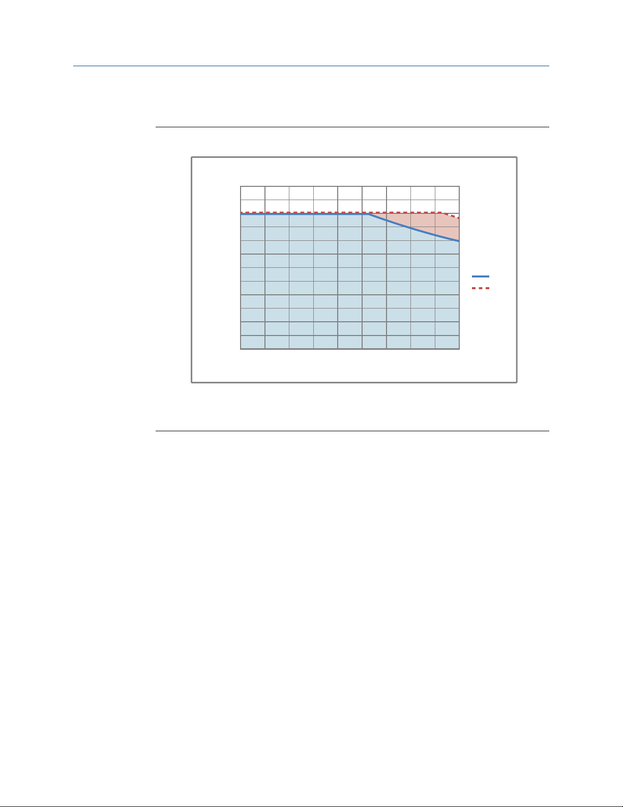
Power cable recommendations for explosion-proof/flameproof meters
300ft 600ft 900ft 1200ft 1500ft 1800ft 2100ft 2400ft 2700ft 3000ft
B
21.6V
24V
14
15
16
17
18
19
20
21
22
23
24
25
26
A
91.44m 182.88m 274.32m 365.76m 457.2m 548.64m 640.08m 731.52m 822.96m 914.4m
Minimum wire gauge (AWG per foot or meter)Figure 1-1:
Planning
A. AWG maximum
B. Distance of installation
Installation Manual 3
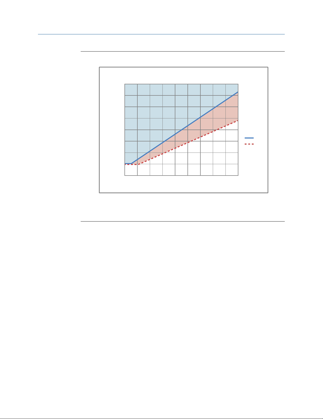
0.000
0
.050
0.100
0.150
0.200
0.250
0.300
0.350
0.400
100m 200m 300m 400m 500m 600m 700m 800m 90 0m 1000m
B
21.6V
24V
A
328.084 ft 656.168ft 984.253ft 1312.34ft 1640.42ft 1968.5ft 2296.59ft 2624.67ft 2952.76ft 3280.84ft
Planning
Figure 1-2:
Minimum wire area (mm2 per meter or foot)
A. Minimum wire area (mm2)
B. Distance of installation
1.4 Other installation considerations
Numerous external factors can affect the meter's successful operation. To ensure that your
system works correctly, consider the factors covered in this section when designing your
installation.
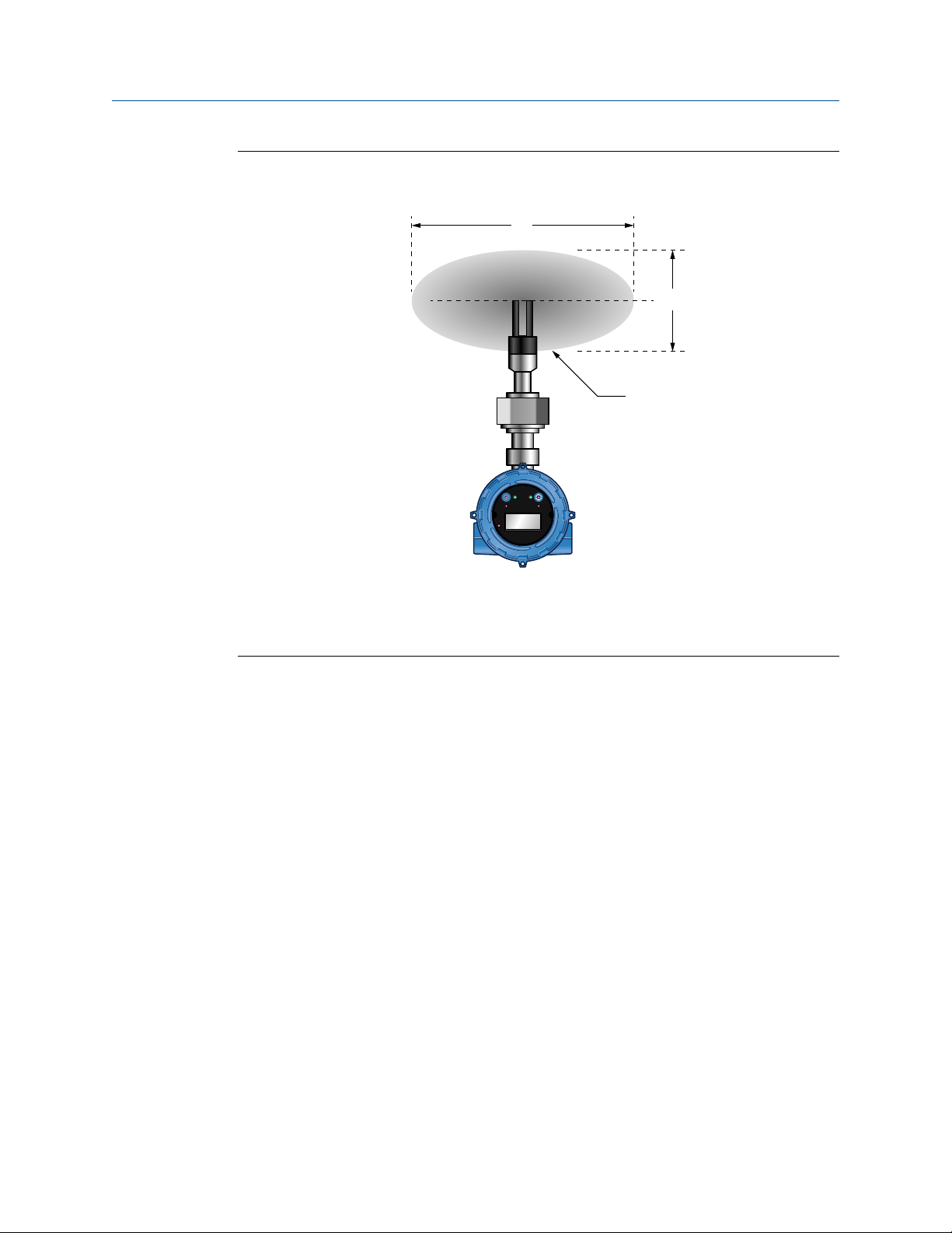
1.4.1 Boundary effect
4 Micro Motion Heavy Fuel Viscosity Meter
Boundary effect refers to the distortion in the wave forms in the process fluid that are caused by reflections from the pipe wall. If the pipe wall is within the meter's effective measurement region, the boundary effect produces measurement inaccuracy.
A
B
C
STATUS
SCROLL SELECT
Planning
Region of measurement boundary or sensitivity (plan view)Figure 1-3:
A. Long axis
B. Short axis
C. Sensitive, or effective, region
The factory calibration compensates for the boundary effect. The meter can be calibrated
for 2-inch, 2.5-inch, or 3-inch pipe. If the meter is installed in a pipe that does not match
the calibration size, the compensation will be inaccurate, and process measurement will
be inaccurate.
Verify that the meter was calibrated for the pipe size you plan to use.
1.4.2 Flow rates
Maintain constant flow rates and velocities that are within the limits specified for the
meter. The fluid flow provides a steady heat flow into the meter installation, and the flow
rate influences the self-cleaning of the meter tines, the dissipation of bubbles, and the
solid contaminants around the meter.
If you install the meter in a bypass configuration (such as in a flow-through chamber), use a
pressure drop, pitot scoop, or a sample pump to maintain flow. When using a sample
pump, place the pump upstream from the meter.
Installation Manual 5
 Loading...