

Page 1
Next Generation Critical Cooling
for Room and Row
Liebert PEX
Effi ciency And Reliability For High Availability Cooling
Chilled Water Models
User Manual
Page 2

Liebert.PEX Chilled Water Series Air Conditioner
User Manual
Version V1.1
Revision date May 6, 2010
BOM 31011830
Emerson Network Power provides customers with technical support. Users may contact the
nearest Emerson local sales office or service center.
Copyright © 2010 by Emerson Network Power Co., Ltd.
All rights reserved. The contents in this document are subject to change without notice.
Emerson Network Power Co., Ltd.
Address: No.1 Kefa Rd., Science & Industry Park, Nanshan District 518057, Shenzhen China
Homepage: www.emersonnetworkpower.com.cn
E-mail: support@emersonnetwork.com.cn
Page 3

Page 4

Contents
Chapter 1 Overview ........................................................................................................................................................... 1
1.1 Model Description ............................................................................................................................................... 1
1.2 Main Components ............................................................................................................................................... 1
1.3 Remote Monitoring Software ............................................................................................................................. 2
1.4 Environmental Requirements ............................................................................................................................ 2
1.4.1 Operation Environment ........................................................................................................................... 2
1.4.2 Storage Environment .............................................................................................................................. 3
Chapter 2 Mechanical Installation ................................................................................................................................... 4
2.1 Installation Preparation ...................................................................................................................................... 4
2.1.1 Transportation And Movement ............................................................................................................... 4
2.1.2 Unpacking ................................................................................................................................................ 4
2.1.3 Inspection ................................................................................................................................................. 5
2.1.4 Installation Notes ..................................................................................................................................... 6
2.2 System Installation Arrangement ...................................................................................................................... 6
2.2.1 General Arrangement .............................................................................................................................. 6
2.2.2 Mechanical Parameters ........................................................................................................................... 7
2.3 Installing Chilled Water AC Unit ...................................................................................................................... 14
2.3.1 Installation Requirement ....................................................................................................................... 14
2.3.2 Installation Procedures ......................................................................................................................... 15
2.4 Piping ................................................................................................................................................................. 19
2.5 Removing Transport Fastener And Vibration Absorber ................................................................................ 21
2.6 Adjusting Water Level Regulator ..................................................................................................................... 24
2.7 Installation Inspection ...................................................................................................................................... 25
Chapter 3 Electric Installation ........................................................................................................................................ 26
3.1 Work Introduction And Installation Notes ...................................................................................................... 26
3.2 Wiring Of Chilled Water AC Unit ...................................................................................................................... 26
3.2.1 Locating Electrical Interfaces ............................................................................................................... 26
3.2.2 Connecting Power Cable Of Chilled Water AC Unit............................................................................ 27
3.2.3 Connecting Control Cables .................................................................................................................. 28
3.3 Installation Inspection ...................................................................................................................................... 29
Chapter 4 System Start-Up Commissioning ................................................................................................................. 30
4.1 Locating MCBs .................................................................................................................................................. 30
4.2 Start-Up Commissioning .................................................................................................................................. 32
4.2.1 Preparation Before Commissioning..................................................................................................... 32
4.2.2 Commissioning Procedures ................................................................................................................. 32
4.2.3 Inspection After Commissioning ......................................................................................................... 33
Chapter 5 iCOM Controller ............................................................................................................................................. 34
5.1 LCD .................................................................................................................................................................... 34
5.2 Button And Indicator Panel .............................................................................................................................. 34
5.3 Structure Chart Of Control Menu ..................................................................................................................... 36
Page 5

5.4 Startup Interface ............................................................................................................................................... 36
5.5 Main Interface .................................................................................................................................................... 36
5.6 USER MENUS .................................................................................................................................................... 37
5.6.1 PASSWORD ........................................................................................................................................... 37
5.6.2 SETPOINTS ............................................................................................................................................ 37
5.6.3 EVENT LOG ............................................................................................................................................ 37
5.6.4 GRAPHICS .............................................................................................................................................. 39
5.6.5 SET ALARMS ......................................................................................................................................... 39
5.6.6 SENSOR DATA ...................................................................................................................................... 40
5.6.7 DISPLAY SETUP .................................................................................................................................... 41
5.6.8 TOTAL RUN HRS ................................................................................................................................... 42
5.6.9 SLEEP MODE ......................................................................................................................................... 43
5.6.10 SERVICE INFO ..................................................................................................................................... 43
5.6.11 ACTIVE ALARMS ................................................................................................................................. 43
5.7 SERVICE MENUS .............................................................................................................................................. 43
5.7.1 PASSWORD LEVEL ............................................................................................................................... 44
5.7.2 SETPOINTS ............................................................................................................................................ 44
5.7.3 STANDBY ............................................................................................................................................... 45
5.7.4 WELLNESS ............................................................................................................................................. 45
5.7.5 DIAGNOSTICS ........................................................................................................................................ 48
5.7.6 SET ALARMS ......................................................................................................................................... 50
5.7.7 CALIBRATION ........................................................................................................................................ 52
5.7.8 NETWORK SETUP ................................................................................................................................. 52
5.7.9 OPTIONS SETUP ................................................................................................................................... 53
5.7.10 SERVICE INFO ..................................................................................................................................... 54
5.8 ADVANCED MENUS .......................................................................................................................................... 54
5.8.1 PASSWORD LEVEL ............................................................................................................................... 54
5.8.2 FACTORY SETUP .................................................................................................................................. 55
5.9 MBV Settings ..................................................................................................................................................... 59
5.10 EVENT NAME AND DEFINITION .................................................................................................................... 60
Chapter 6 Application Of INTELLISLOT ........................................................................................................................ 64
6.1 Introduction Of Host Communication Card .................................................................................................... 64
6.2 Installing Host Communication Card .............................................................................................................. 65
6.3 Commissioning Host Communication Component ....................................................................................... 65
6.3.1 Setting HyperTerminal .......................................................................................................................... 66
6.3.2 Setting 485 Communication Card ........................................................................................................ 67
6.3.3 Setting TCP/IP Communication Card ................................................................................................... 68
6.3.4 Setting SNMP Parameters Of TCP/IP Communication Card .............................................................. 70
6.4 Host Communication Networking Diagram .................................................................................................... 73
Chapter 7 System Operation And Maintenance ........................................................................................................... 74
7.1 System Diagnosis Test ..................................................................................................................................... 74
7.1.1 Self-diagnosis Function ........................................................................................................................ 74
7.1.2 Electric Control Part .............................................................................................................................. 74
7.2 Filter ................................................................................................................................................................... 75
7.3 Fan Kit ................................................................................................................................................................ 76
Page 6

7.3.1 Fan Bearing And Blades ....................................................................................................................... 76
7.3.2 Belt .......................................................................................................................................................... 76
7.3.3 Motor....................................................................................................................................................... 76
7.4 Infrared Humidifier ............................................................................................................................................ 76
7.5 Electrical Heater ................................................................................................................................................ 78
7.6 Water Flow Control Valve ................................................................................................................................. 79
Chapter 8 Failure Diagnosis And Troubleshooting ...................................................................................................... 80
Appendix 1 The Structure Chart Of Electric Control Box ............................................................................................ 83
Appendix 2 Circuit Diagram ........................................................................................................................................... 86
Appendix 3 The Structure Chart Of Micro-processing Controller Menu .................................................................... 87
Page 7

Page 8

Chapater 1 Overview 1
Liebert.PEX Chilled Water Series Air Conditioner User Manual
Chapter 1 Overview
The Liebert.PEX chilled water air conditioner (chilled water AC for short) is a medium-large sized precision
environment control system configured with electrical heater and humidifier, suitable for the environment
control of the equipment room or computer room. It uses the chilled water supplied by the cooling water units.
It aims to provide a sound operation environment for precision equipment, such as sensitive equipment,
industry processing equipment, communication equipment and computers.
This chapter introduces the model description, main components and environmental requirements of chilled
water AC.
1.1 Model Description
The model description of the chilled water AC is shown in Figure 1-1.
P31
10VC2MS1RZ0
0
12345
678
9
10 11 12 13 14 15
Global PEX Chilled Water Model Nomenclature
Product R ang e
P
PEX
No. Modules-Bays/Fans
1
2
3
One
Two
Three
Nominal kW
20, 30, 40 to 150
Air Path
F
G
U
V
D
Downflo w (Forward Curve)
Downflow (EC Backward Curve)
Upflow (Forward Curve)
Upflow (EC Backward Curve)
Upflow Ducted (Forward Curve)
Cooling Type
C
Chilled W ater
Cooling Control
2
3
2 way CWV, CW, zero compressors
3 way CWV, CW, zero compressors
Voltage
M
400/3/50
iCOM Display
S
L
Small Disp lay
Large Display
Reheat Type
1
2
0
None
1 Stage
2 Stage
Humidifier
0
S
R
None
Infrared
Steam Ge nerating
Fac tor y C o nf igura ti o n Number
Z
A-Z
A-Z
Aust ralia & Ne w Ze aland
Options
Options
-
-
-
-
-
-
-
-
-
-
-
-
-
-
-
-
-
-
-
-
-
-
-
-
Figure 1-1 Model description
1.2 Main Components
The chilled water AC unit includes heat exchanger, infrared humidifier, fan, electrical heater, water flow
control valve and micro-processing controller.
Heat exchanger
Use finned-tube heat exchanger with high heat emission efficiency. The model-specific distributions can
ensure the even distribution of chilled water in each loop and greatly improve the efficiency of the heat
exchanger, as well as minimize the water resistance of heat exchanging coil.
Page 9
2 Chapter 1 Overview
Liebert.PEX Chilled Water Series Air Conditioner User Manual
Infrared humidifier
Configure with infrared humidifier which is easy for teardown, cleaning and maintenance. It is adjustable to a
wide range of water qualities, with fast startup and high humidifying efficiency.
Fan
Use forward centrifugal fan with high efficiency and reliability, large airflow and long blowing distance. With
the belt transmission mechanism, it is easy for maintenance. The user can also select electronically
commutated (EC for short) fan with backward blades. EC fan is energy-saving and space-saving with high
efficiency and low noise. It is also subject to stepless speed regulation. For the structure of EC fan downflow
unit, the solution of air supply by putting fan unit under floor is considered, which can significantly improve
the efficiency of air supply.
Electrical heater
Use screw finned U type stainless steel electrical heating tube, with fast heating speed and evenly distributed
heat volume.
Water flow control valve
The water flow control valve can adjust the chilled water flow quantity according to the cooling requirement. It
is connected to the system pipes with live joints, easy for field installation and maintenance, thus reducing
the project installation cost.
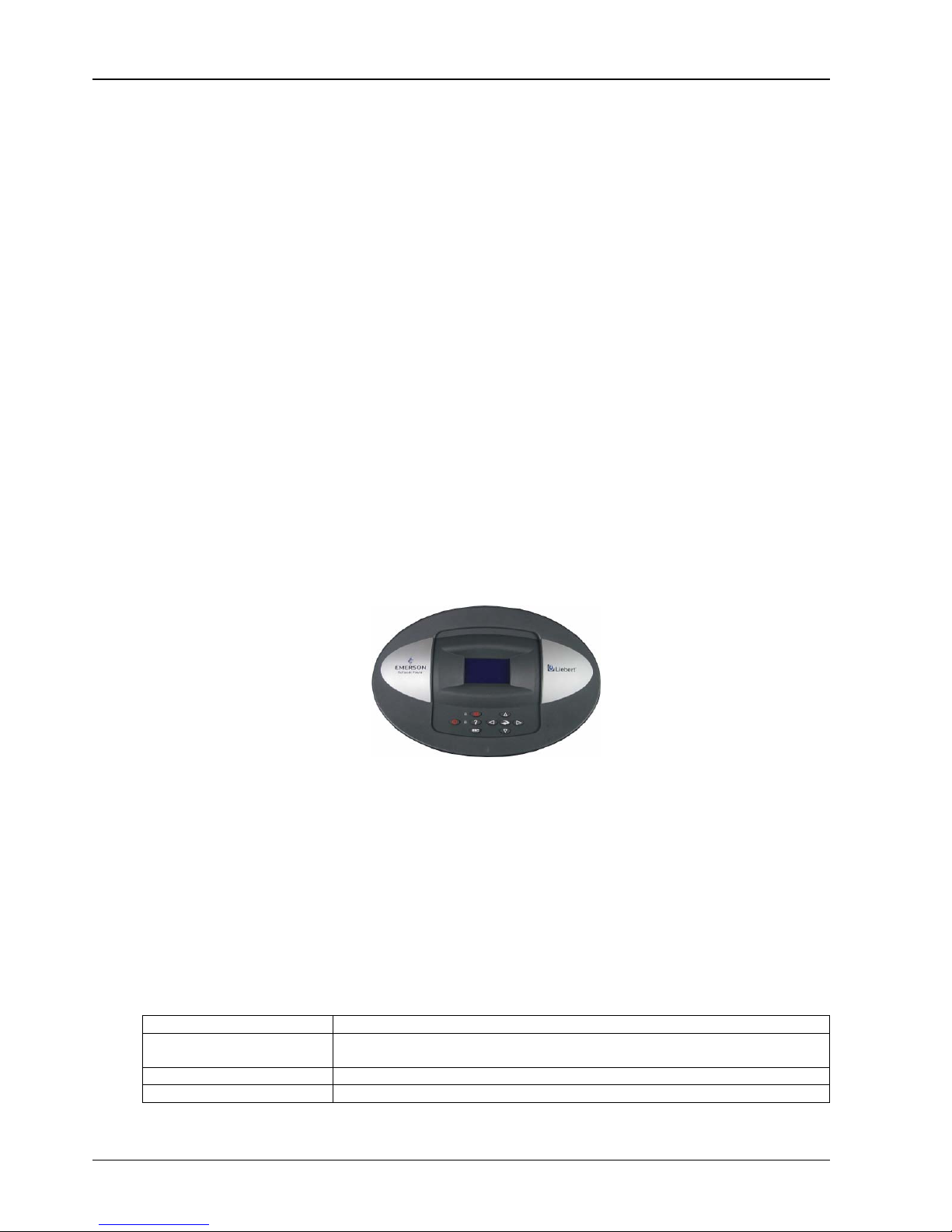
Micro-processing controller
The micro-processing controller of the chilled water AC uses an LCD screen with blue backlight and 128 × 64
dots. The user interface operation is simple. The multi-level password protection can effectively prevent
illegal operation. It also features power failure auto-restoration and high / low voltage protection function. The
operation time of components is available through the menus. The expert-level fault diagnosis system can
display the current fault information automatically, facilitating the maintenance. It can store up to 400 records
of historical events. The panel of micro-processing controller is shown in Figure 1-2.
Figure 1-2 Micro-processing controller panel
1.3 Remote Monitoring Software
The chilled water AC can communicate with the host computer through a configured communication port to
receive the control of the host software.
1.4 Environmental Requirements
1.4.1 Operation Environment
See Table 1-1 for details.
Table 1-1 Operation environment requirement
Item Requirement
Operation range
Indoor temperature: 4°C ~ 40°C
Chilled water supply temperature: 5°C ~ 13°C
Altitude < 1000m. Above that, derating is required
Operation voltage range 400V (-10% ~ +10%), three-phase AC, 50Hz
Page 10

Chapater 1 Overview 3
Liebert.PEX Chilled Water Series Air Conditioner User Manual
1.4.2 Storage Environment
See Table 1-2 for details.
Table 1-2 Storage environment requirement
Item Requirement
Storage environment Indoor, clean, no dust
Ambient humidity 5%RH ~ 85%RH (non-condensing)
Ambient temperature -20°C ~ +54°C
Storage time
Total transportation and storage time should not exceed 6 months. Otherwise, the performance
needs to be re-evaluated
Page 11
4 Chapter 2 Mechanical Installation
Liebert.PEX Chilled Water Series Air Conditioner User Manual
Chapter 2 Mechanical Installation
This chapter introduces the mechanical installation of the chilled water AC, including the transportation and
movement, unpacking, inspection, installation notes and installation procedures.
2.1 Installation Preparation
2.1.1 Transportation And Movement
Railroad transportation and shipping are the recommended means of transportation. If truck transportation is
unavoidable, choose roads that are less bumpy in order to protect the equipment.
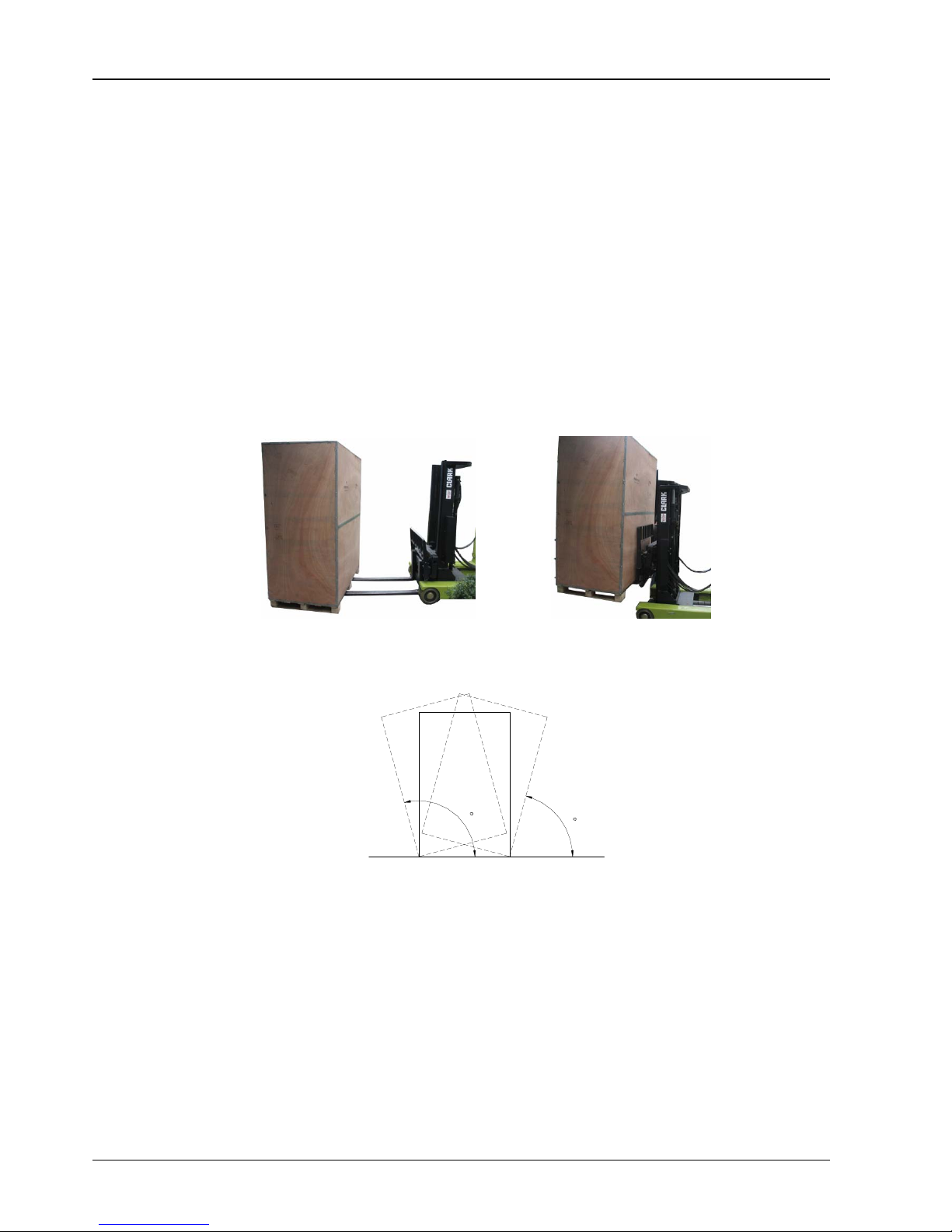
The chilled water AC is heavy (see Table 2-1 for the weight parameters). It is recommended to use a
mechanical handbarrow such as an electric forklift when unpacking and moving the equipment to the place
closest to the installation site. Insert the tines of the forklift below the pallet, as shown in Figure 2-1. Align the
tines with the center of gravity to prevent the unit from falling over.
Figure 2-1 Fork direction
Keep the obliquity within 75° ~ 105° during the movement, as shown in Figure 2-2. Extreme incline is not
allowed.
1
0
5
7
5
Figure 2-2 Moving obliquity
2.1.2 Unpacking
Move the equipment to the place closest to the final installation site and then unpack it.
Follow the procedures below to unpack the unit:
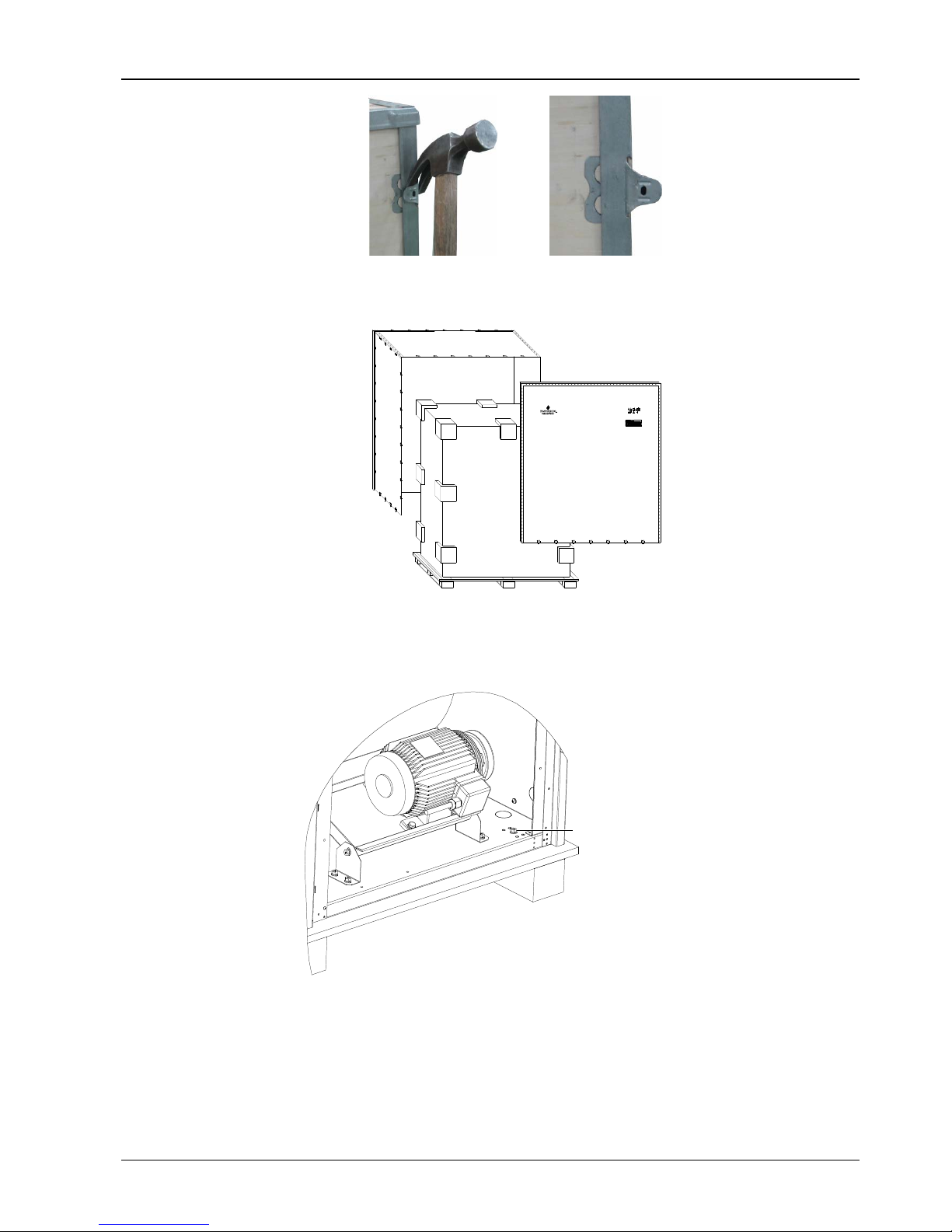
1. Removing the side boards and top cover
The chilled water AC uses international packaging. You can use a hammer or straight screwdriver to
straighten the hook, as shown in Figure 2-3.
Page 12
Chapter 2 Mechanical Installation 5
Liebert.PEX Chilled Water Series Air Conditioner User Manual
Figure 2-3 Straightening the hook
At first, straighten all the hooks that fix side board I, and remove side board I. Then straighten all the hooks
that fix side board II, and remove side board II. At last remove top cover III, as shown in Figure 2-4.
Kg
1790 x 950 x 2020mm
1816 x 976 x 2175mm
I
I
III
II
II
Figure 2-4 Removing side boards and top cover
2. Removing the pallet
The chilled water AC is fixed onto the pallet with M10 × 70 screws, as shown in Figure 2-5. You can use an M10
open-end spanner, a ratchet spanner or a sleeve to remove the fixing screws.
底板固
定
Pallet fixing screw (M10 70)
×
Figure 2-5 Fixing screw position of pallet
2.1.3 Inspection
After receiving the product, you should check it against the packing list. If any parts are found missing,
distorted or damaged, please report to the carrier immediately. If any covert defects are found, please report
to the carrier and the local office of Emerson Network Power Co., Ltd.
Page 13

6 Chapter 2 Mechanical Installation
Liebert.PEX Chilled Water Series Air Conditioner User Manual
2.1.4 Installation Notes
To realize the designed performance and maximum product life, correct installation is vital. This section
should be used in conjunction with local industry standards for mechanical and electrical installations. Note
the following items:
1. The chilled water AC is designed for integrated floor installation. It should be installed on the floor of the
equipment room or computer room.
2. Before the installation, make sure that the installation environment meets the requirements (see 1.4
Environmental Requirements) and the building should be transformed to accommodate the construction work
of piping, wiring and ventilation ducts.
3. Follow the design drawings strictly when installing the equipment, and reserve the space for maintenance.
The engineering dimensions drawings provided by the manufacturer can serve as a reference.
2.2 System Installation Arrangement
2.2.1 General Arrangement
The general arrangement of the chilled water AC is shown in Figure 2-6.
Chille d wate r i nlet
Chille d wate r o utlet
Blance valve or iso lation valve*
Water filler
Isolation
valve
Drain valve
Hose
interf ac e
Welding interface of chilled
water inlet and outlet
Water flow regulating valve
BPH E coil
Exhaust valve
Balancing valve or is olatio n valve*
Water filter
Figure 2-6 General arrangement diagram
Note
1. : Factory piping.
2.
: Field piping (by technicians).
3. *: Components are not supplied by Emerson but are recommended for proper circuit operation and maintenance.
4. After the project installation, exhaust the AC unit before filling water to ensure the efficiency of the heat exchanger.
5. In winter, the AC unit in northern area does not operate for a long term; you must empty the water in AC unit to protect the
heat exchanger from frost cracking.
Page 14
Chapter 2 Mechanical Installation 7
Liebert.PEX Chilled Water Series Air Conditioner User Manual
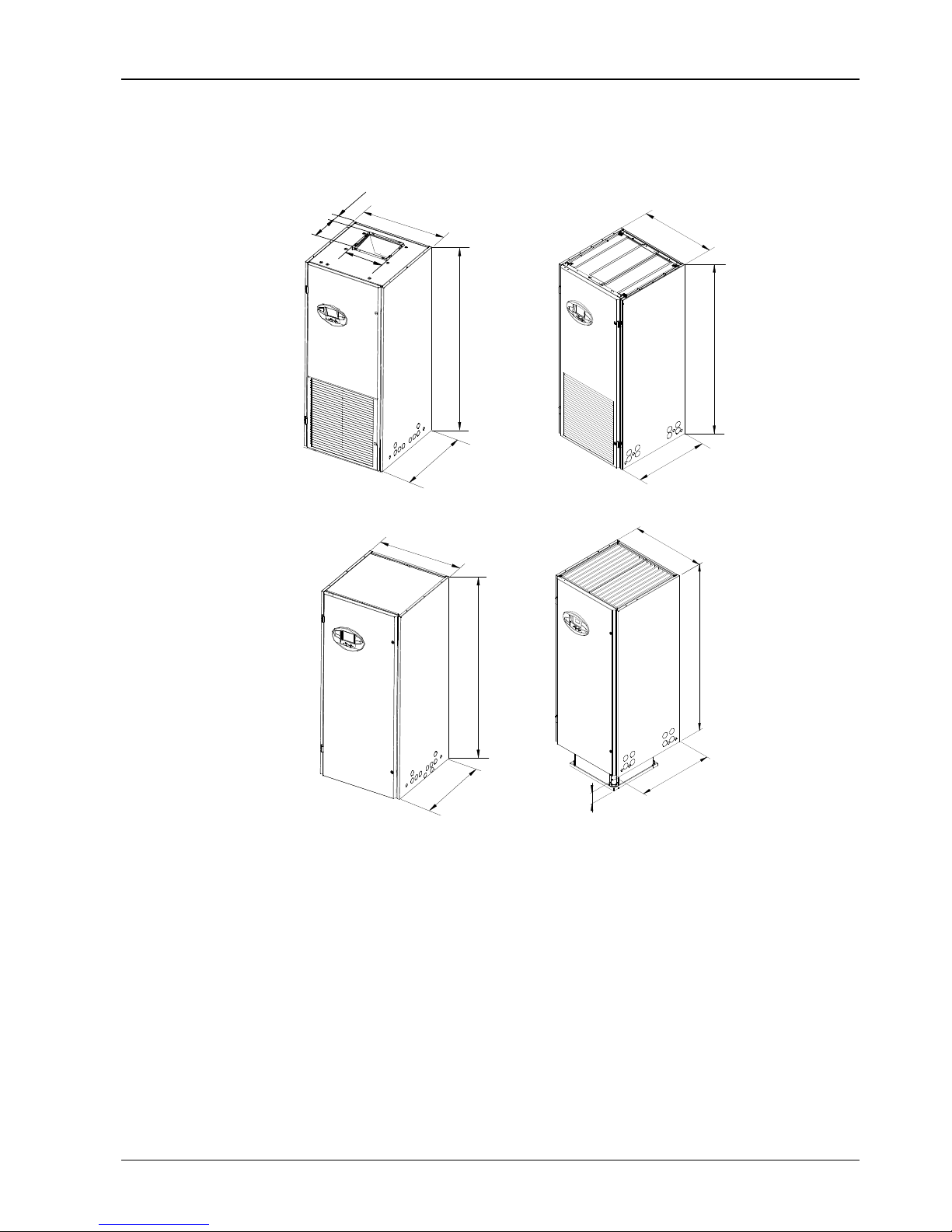
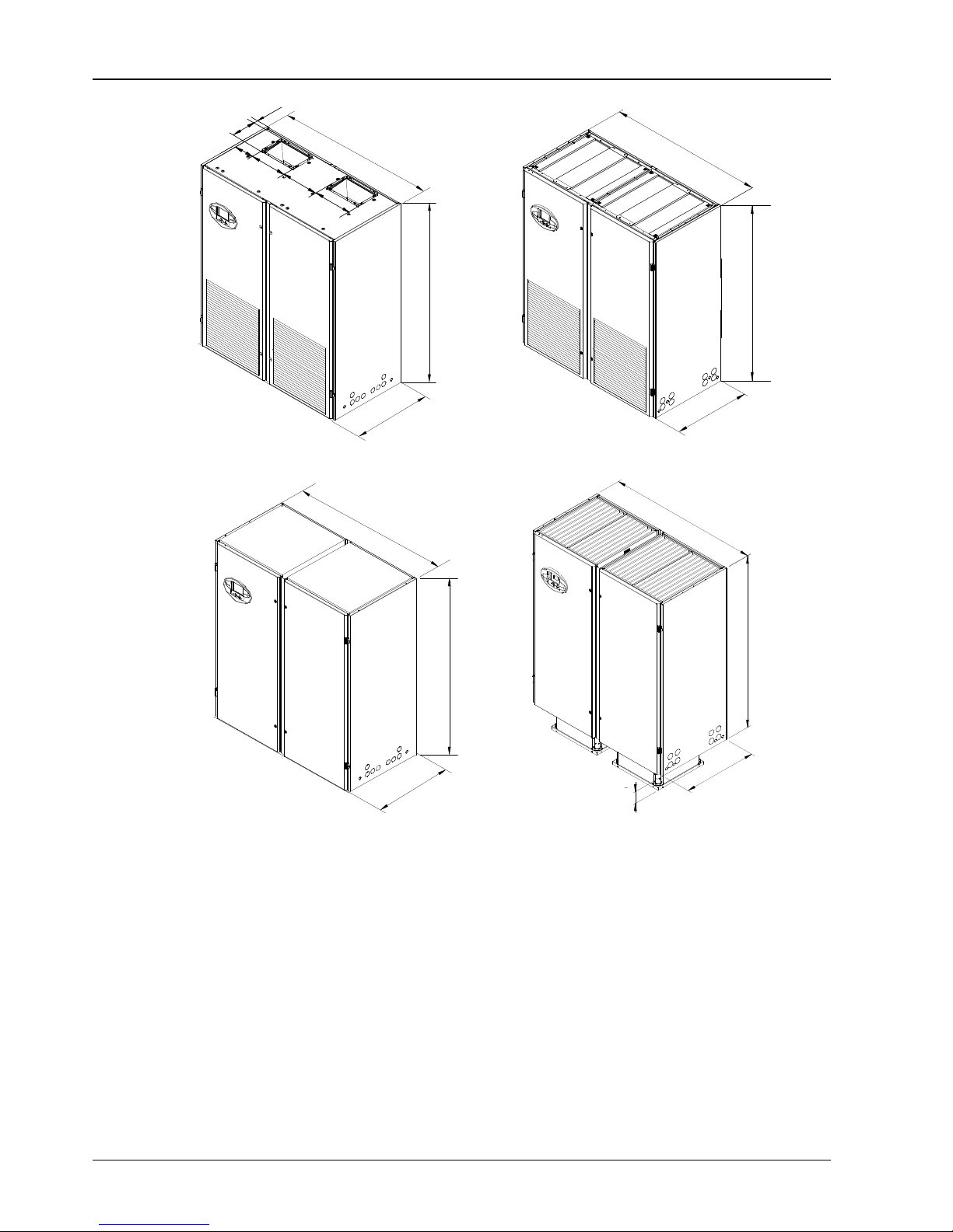
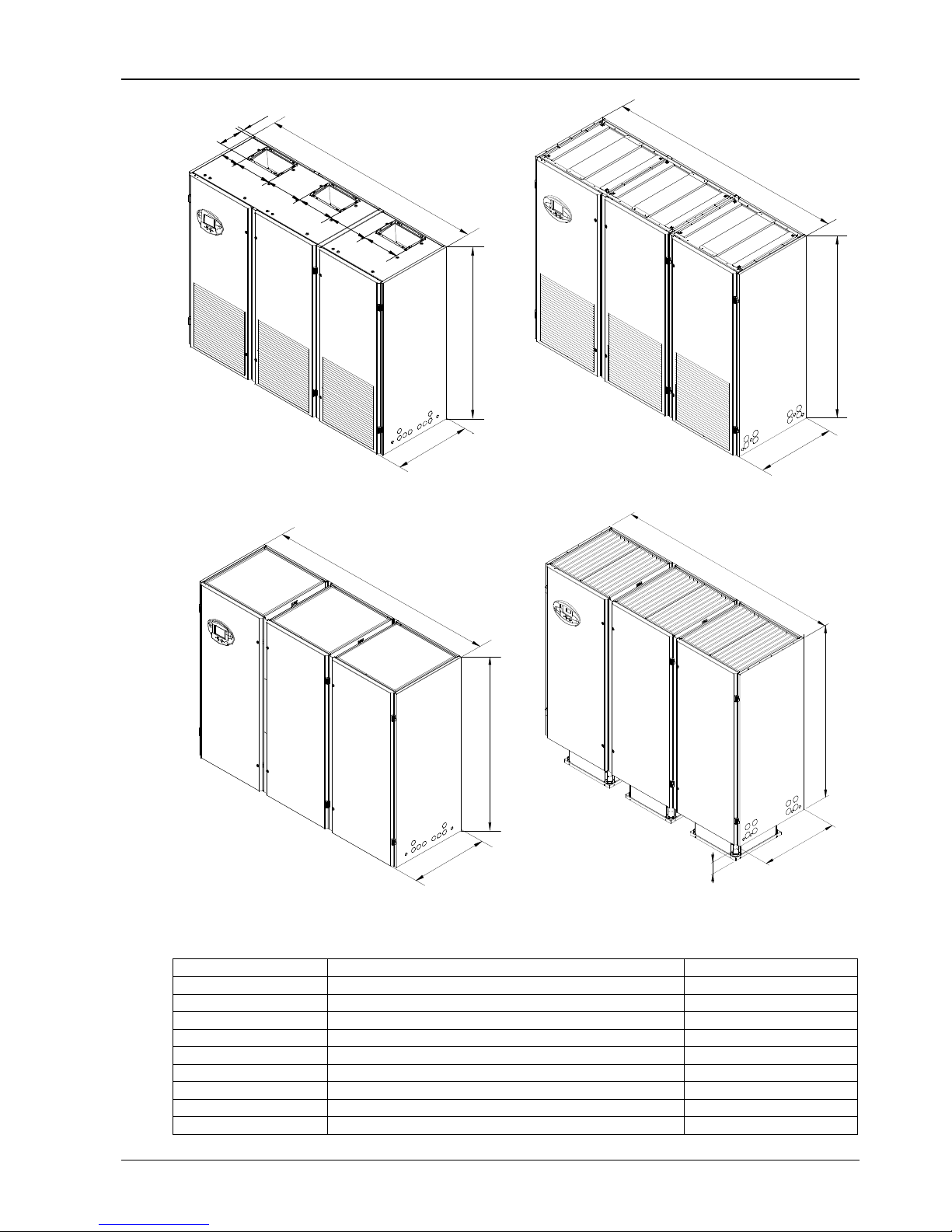
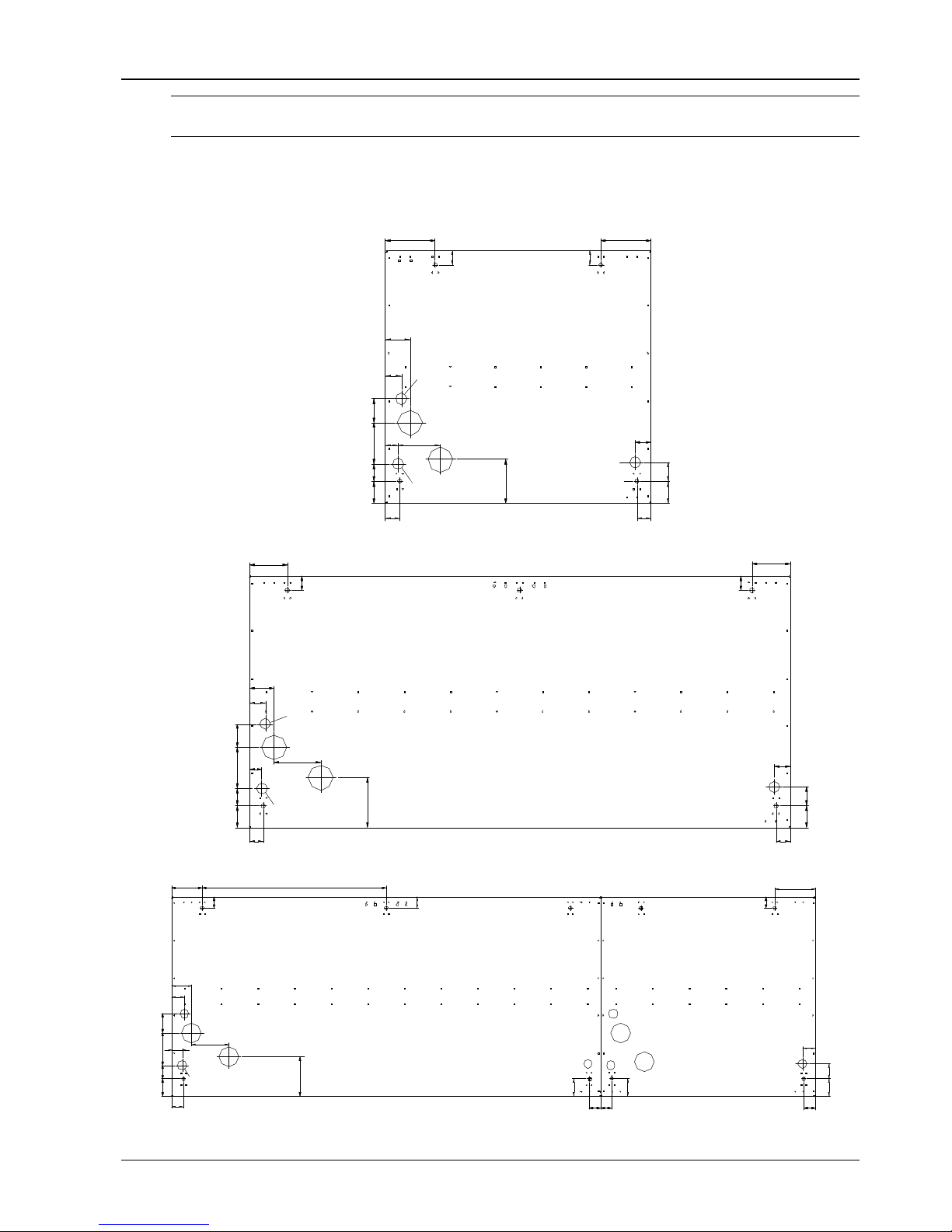
2.2.2 Mechanical Parameters
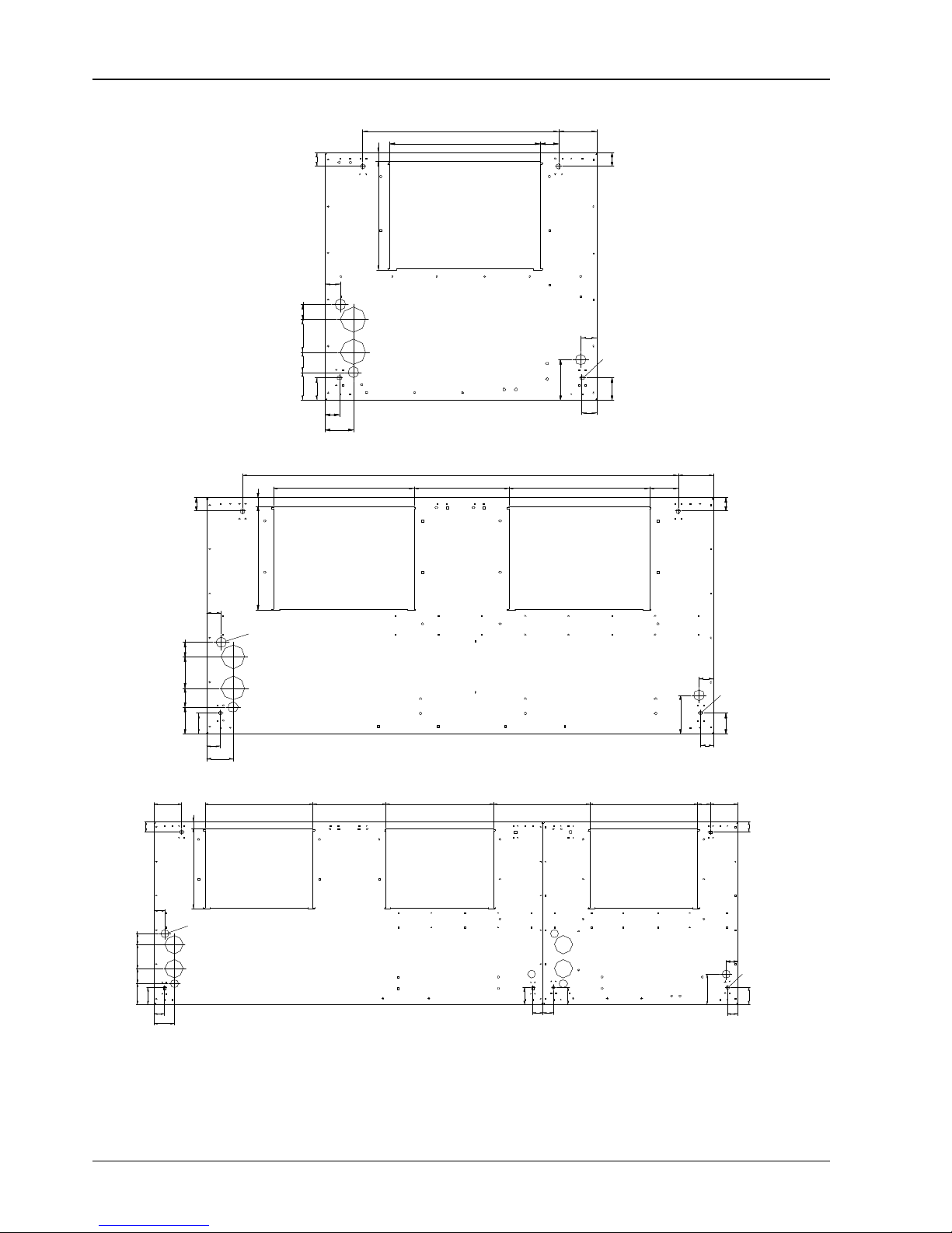
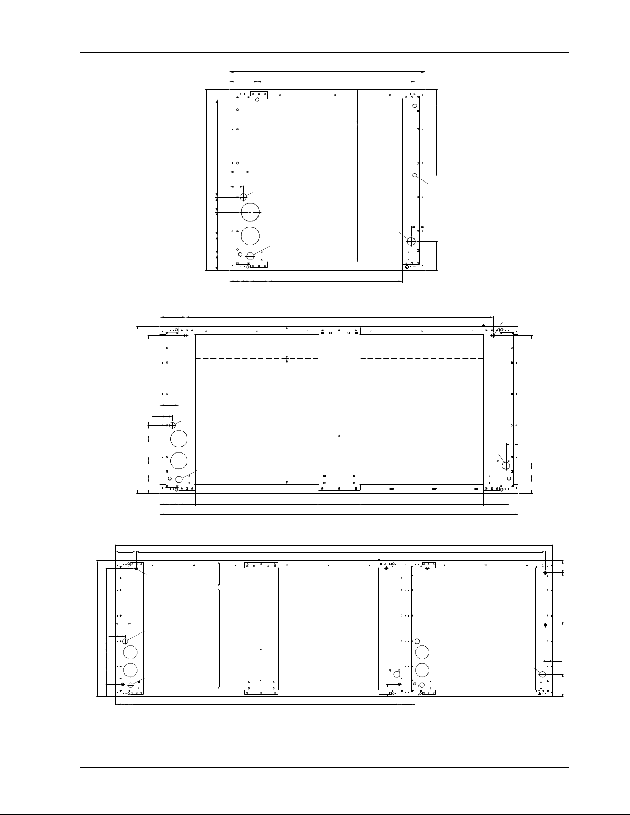
Dimensions
The dimensions of the chilled water AC are shown in Figure 2-7, Figure 2-8, Figure 2-9 and Table 2-1.
8
7
4
8
5
3
1970
8
5
3
1970
8
7
4
3
8
1
6
6
4
7
0
85
3
1970
8
7
4
8
5
3
1970
8
7
4
Upflow unit (forward fan) Upflow unit (backward fan)
1970
8
7
4
8
5
3
8
5
3
1970
8
7
4
8
7
4
1970
8
5
3
280
320
8
5
3
1970
8
7
4
Downflow unit (forward fan) Downflow unit (backward fan)
Figure 2-7 One-bay series (unit: mm)
Page 15
8 Chapter 2 Mechanical Installation
Liebert.PEX Chilled Water Series Air Conditioner User Manual
1
7
0
4
1970
8
7
4
1
7
0
4
1970
8
7
4
3
8
1
6
6
2
3
3
4
7
0
4
7
0
3
4
5
1970
8
7
4
1
70
4
1
7
0
4
1970
8
7
4
Upflow unit (forward fan) Upflow unit (backward fan)
1
7
0
4
1970
8
7
4
1
7
0
4
1970
8
7
4
1
7
0
4
1970
8
7
4
280
320
1
7
0
4
1970
8
7
4
Downflow unit (forward fan) Downflow unit (backward fan)
Figure 2-8 Two-bay series (unit: mm)
Page 16
Chapter 2 Mechanical Installation 9
Liebert.PEX Chilled Water Series Air Conditioner User Manual
2
5
5
3
1970
8
7
4
2
5
5
3
1970
8
7
4
6
6
3
8
1
2
3
3
4
7
0
4
7
0
3
4
5
4
7
0
3
8
2
1970
2
55
3
8
7
4
2
5
5
3
1970
8
7
4
Upflow unit (forward fan) Upflow unit (backward fan)
2
5
5
3
8
7
4
1970
2
5
5
3
1970
8
7
4
8
7
4
1970
2
5
5
3
280
320
8
7
4
1970
2
5
5
3
Downflow unit (forward fan) Downflow unit (backward fan)
Figure 2-9 Three-bay series (unit: mm)
Table 2-1 Dimension
Model Dimensions (W × D × H) (mm) Net weight (kg)
P1020 853 × 874 × 1970 ≤ 315
P1030 853 × 874 × 1970 ≤ 315
P1040 853 × 874 × 1970 ≤ 338
P1050 853 × 874 × 1970 ≤ 343
P2050 1704 × 874 × 1970 ≤ 476
P2070 1704 × 874 × 1970 ≤ 476
P2090 1704 × 874 × 1970 ≤ 505
P2100 1704 × 874 × 1970 ≤ 530
P3110 2553 × 874 × 1970 ≤ 656
Page 17
10 Chapter 2 Mechanical Installation
Liebert.PEX Chilled Water Series Air Conditioner User Manual
Model Dimensions (W × D × H) (mm) Net weight (kg)
P3140 2553 × 874 × 1970 ≤ 706
P3150 2553 × 874 × 1970 ≤ 715
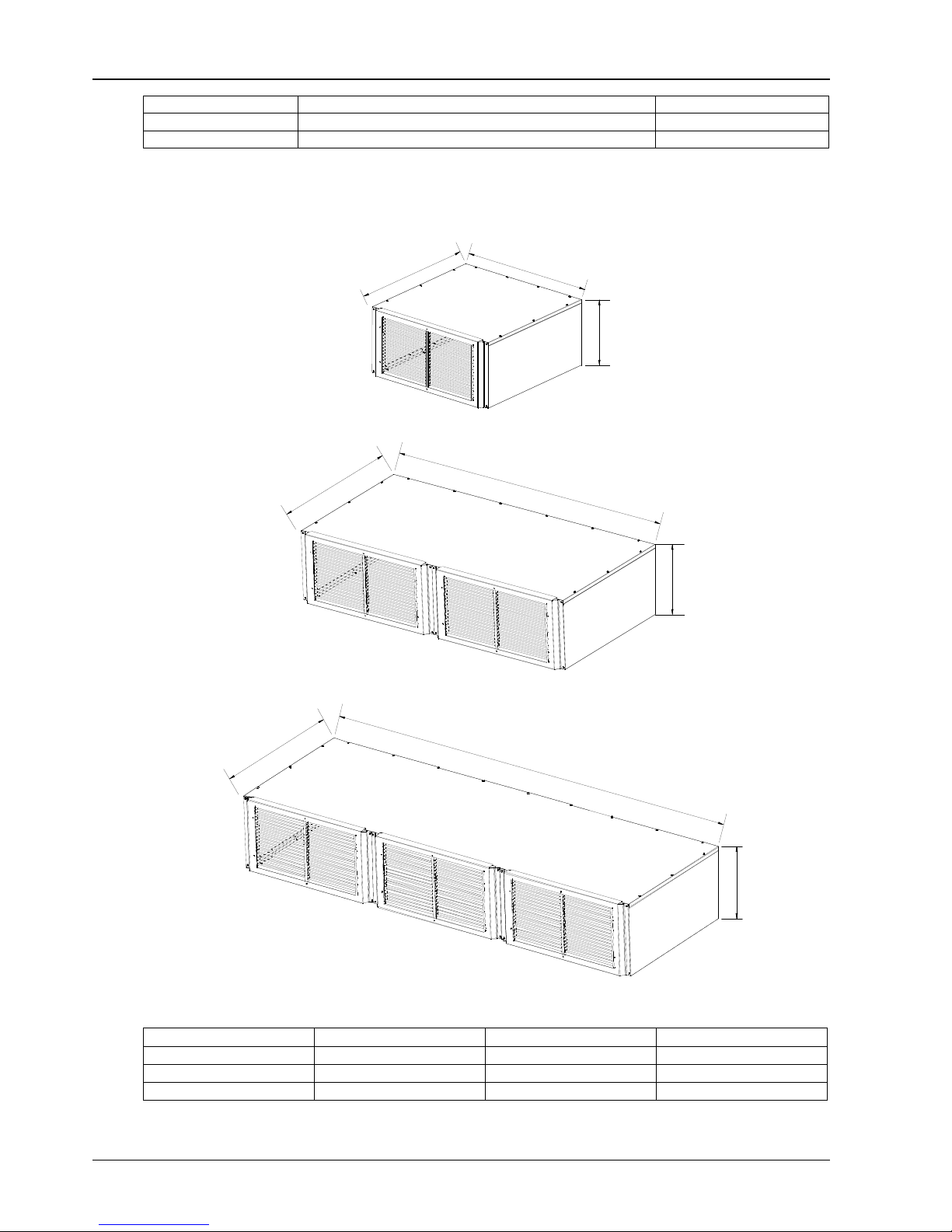
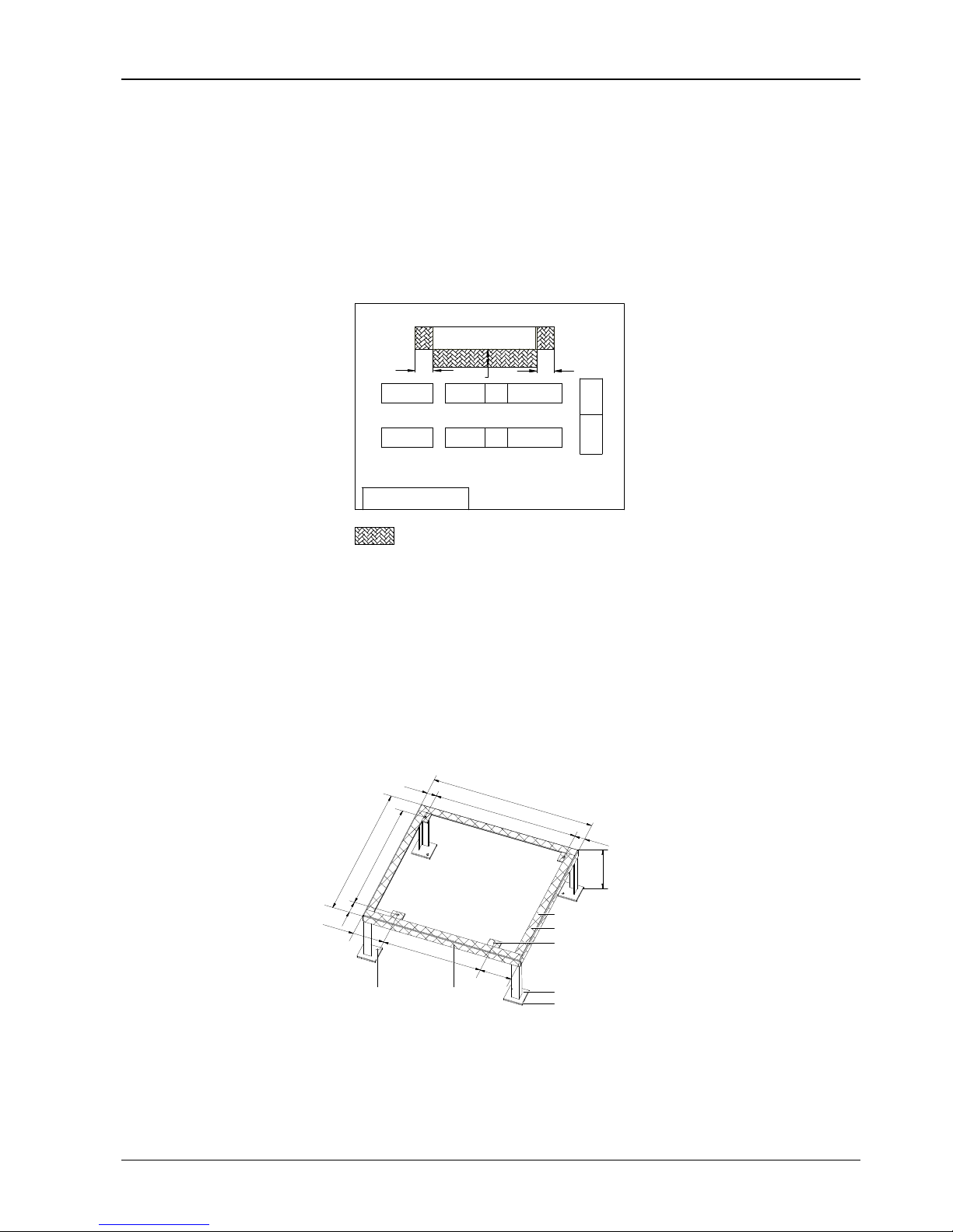
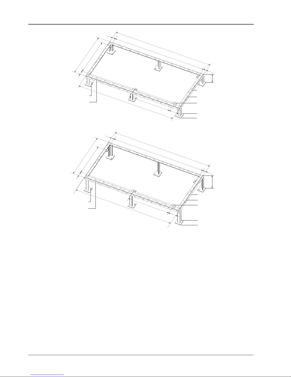
Plenum dimensions
You can select the air supply plenum with grids for the upflow system. The appearance of the plenum is
shown in Figure 2-10, Figure 2-11 and Figure 2-12. The detailed dimensions are listed in Table 2-2.
C
B
A
Figure 2-10 One-bay plenum
C
B
A
Figure 2-11 Two-bay plenum
C
B
A
Figure 2-12 Three-bay plenum
Table 2-2 Dimensions of plenum (unit: mm)
Type
A B C
One-bay 867 853 400 (600, optional)
Two-bay 867 1704 400 (600, optional)
Three-bay 867 2553 400 (600, optional)
Page 18
Chapter 2 Mechanical Installation 11
Liebert.PEX Chilled Water Series Air Conditioner User Manual
Note
If the height of the plenum selected for air conditioner unit exceeds 600mm, consult the factory for non-standard production.
Base cut-out location dimensions
The base cut-out position dimensions of the chilled water AC are shown in Figure 2-13, Figure 2-14 and Figure
2-15.
6070
45
50
5570
45
40 134.7
130.1
138.4
160
45
45
160
78.3
50
74.9
Condensed water drain hole
Chilled water drain hole
Chilled water inlet opening
Water inlet opening
for humidifier
Cable inlet/
outlet opening
4 bottom plate
fastening holes
One-bay series
74.9
130.155
70
40
146.4
50
78.3
45
120
45
45
120
50
6070
45
159.6
Condensed water drain hole
Chilled water drain hole
Chilled water inlet opening
Cable inlet/outlet opening
4 bottom plate fastening holes
Water inlet opening
for humidifier
Two-bay series
146.4
50
40
130.1
74.9
5570
45
159.6
78.3
70
4545
72.5
50
45
70 60
160
45
730
45
45
120
Condensed water drain hole
Chilled water drain hole
Chilled water inlet opening
Water inlet opening
for humidifier
Cable inlet/outlet opening
7 bottom plate fastening holes
Three-bay series
Page 19
12 Chapter 2 Mechanical Installation
Liebert.PEX Chilled Water Series Air Conditioner User Manual
Figure 2-13 Base cut-out locations of the upflow series (unit: mm)
612
471
119
45
45
350
48
48.5
105
6590
72.5
45
88.5
45
72.5
130
50
29
56.8
Air supply outlet
Condensed water drain hole
Chilled water inlet opening
Chilled water drain hole
Water inlet opening for humidifier
Cable inlet/
outlet opening
4 bottom plate
fastening holes
One-bay series
1460
318471
29
45
350
48
48.5
1056590
70
471 96.8
120
45
50
45
88.5
130
45
70
Air supply outlet Air supply outlet
Condensed water drain hole
Chilled water inlet opening
Chilled water drain hole
Water inlet opening for humidifier
Cable inlet/outlet opening
4 bottom plate
fastening holes
Two-bay series
120
45
29
471 318 471 420
350
48
48.5105
65
90
70
88.5
45
471 56.8 119
45
72.5
45
130
4545
70
72.5
50
Air supply outlet
Condensed water drain hole
Chilled water inlet opening
Chilled water drain hole
Water inlet opening for humidifier
Cable inlet/outlet opening
6 bottom plate
fastening holes
Air supply outlet
Air supply outlet
Three-bay series
Figure 2-14 Base cut-out locations of the forward fan downflow series (unit: mm)
Page 20
Chapter 2 Mechanical Installation 13
Liebert.PEX Chilled Water Series Air Conditioner User Manual
850
686
89
429
798
651058172
58
45 43 79
583
601
130
60
306
73
157
4 bottom plate
fastening holes
Air supply outlet
Condensed water drain hole
Chilled water inlet opening
Chilled water drain hole
Water inlet opening
for humidifier
Cable inlet/
outlet opening
One-bay series
120
1460
157
623
6070
59
122583200
1700
583
78
4445
429
789
651058470
58
89
601
4 bottom plate
fastening holes
Air supply outlet
Air supply outlet
Condensed water drain hole
Chilled water inlet opening
Chilled water drain hole
Water inlet opening
for humidifier
Cable inlet/
outlet opening
Two-bay series
6 bottom plate
fastening holes
Condensed
water drain hole
Air supply outlet Air supply outlet
Chilled water inlet opening
Chilled water drain hole
Water inlet opening for
humidifier
Cable inlet/outlet opening
120
2550
2385
89
429
798
58
6510584
70
157
601
4544
1566
90
70
73
Air supply outlet
130
60
306 73
Three-bay series
Figure 2-15 Base cut-out locations of the backward fan downflow series (unit: mm)
Page 21
14 Chapter 2 Mechanical Installation
Liebert.PEX Chilled Water Series Air Conditioner User Manual
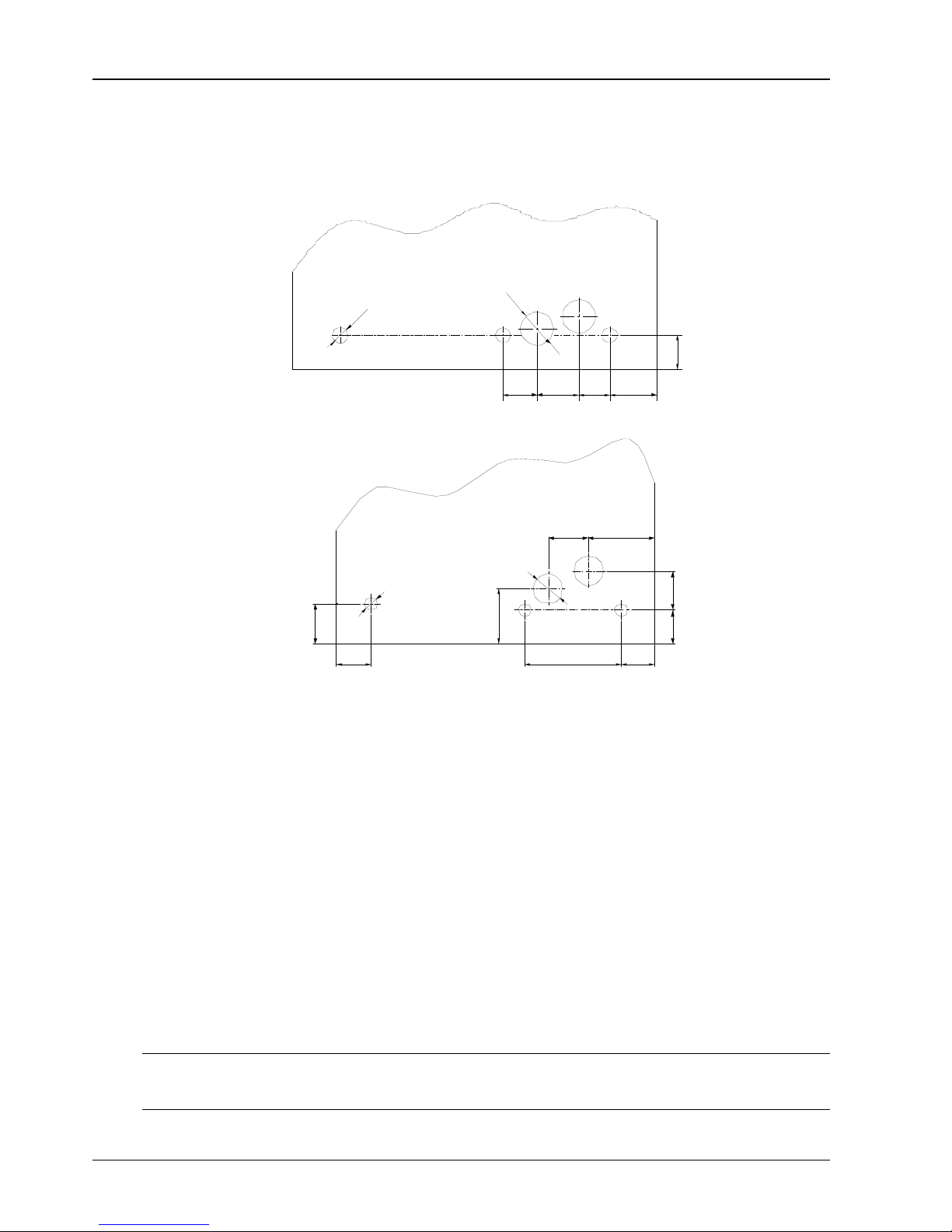
Side panel cut-out locations
If piping and wiring from the base are difficult, connection from side panel can be selected. The locations and
dimensions of knock-out holes are shown in Figure 2-16. You can select the in and out holes according to the
factual needs, but must confirm that any two cables of pipe, power cable and signal cable cannot use the
same hole.
2-Ф 80 knock-out holt
3-Ф 35 knoc k-o ut holt
79.3
95.7 70
110.8
80
Φ
Φ
knock-o ut hole
knock-o ut hole
Upflow series
108.5 174.7
90
90.2
253.5
147.5
91.4
107
105.5
2-Ф 80 knock-out holtΦ
3-Ф 35 knoc k-ou t holt
Φ
knock-o ut hole
knock-out hole
Downflow series
Figure 2-16 Knock-out holes of side panel (unit: mm)
2.3 Installing Chilled Water AC Unit
2.3.1 Installation Requirement
Equipment room requirement
The requirements of equipment room are as follows:
1. Damp proof and heat preservation must be done to make sure that the system can operate normally.
2. The equipment room should have good heat insulation and sealed damp proof layer. The damp proof layer
of the ceiling and walls must use polyethylene film, and the coating of the concrete wall and the floor must be
damp proof.
3. Prevent the outdoor air from entering the equipment room, because the outdoor air that enters the
equipment room may increase the load of heating, cooling, humidifying and dehumidification of the system. It
is recommended that the inhalation of outdoor air be kept below 5% of the total indoor airflow.
4. All the doors and windows should be closed and the seams should be as narrow as possible.
Installation space requirement
Note
The chilled water AC will generate condensed water, and water leakage may damage the precision equipment nearby. So do not
install the system in the vicinity of any precision equipment, and the installation site must provide drain pipes.
1. To ensure normal operation, the installation space for the indoor unit shall be capacious enough.
Page 22
Chapter 2 Mechanical Installation 15
Liebert.PEX Chilled Water Series Air Conditioner User Manual
2. Too small space for the indoor unit will baffle the airflow, shorten the cooling cycle; the air supply and air
exhaust may mix, and the decibel may rise.
3. Do not place the indoor unit in a concave or at the end of a strip area.
4. Do not huddle multiple indoor units, lest there should be mixed airflow, unbalanced load and competitive
operation.
5. For the convenience of daily maintenance, do not install other equipment (such as smoke detector) above
the cabinet.
6. Backward fan downflow unit: because the fan needs to sink during the operation, so the floor must be
higher than 400mm.
Figure 2-17 shows the installation place of the indoor unit.
Good place
Unit
Note:
The reserved maintenance space during the installation
600600
600
Bad place
Unit
Figure 2-17 Installation place of indoor unit (unit: mm)
Maintenance space requirement
Leave more than 600mm of maintenance space in the front and on both sides of the chilled water AC unit, as
shown in Figure 2-17.
2.3.2 Installation Procedures
The installation procedures of indoor unit are as follows:
1. Make the mounting base according to the dimensions in Figure 2-18, Figure 2-19 and Figure 2-20 and the
requirements in Table 2-3. You can make it yourself or contact Emerson Network Power Co., Ltd. for
non-standard production.
1
6
1
.
5
5
3
0
1
6
1
.
5
6
7
6
8
0
.
5
8
2
0
4
6
.
5
7
6
0
8
5
3
H
4
6
.
5
F ront side of cabinet
R ubbe r c ushion
(lateral)
Installa tion hole
for expansion bolt
R e ar side of ca bine t
S teel plate
R ubbe r c ushion ( bottom)
Angle steel
R ubbe r c ushion ( top)
4-Ф 14 cabinet installation hole
Φ
Figure 2-18 Mounting base of one-bay series (unit: mm)
Page 23
16 Chapter 2 Mechanical Installation
Liebert.PEX Chilled Water Series Air Conditioner User Manual
1
7
0
3
7
3
0
1
2
1
.
5
6
7
8
2
0
6
8
3
4
6
.
5
1
6
1
0
1
7
0
3
H
4
6
.
5
F ront side of cabinet
Installation hole
for expansion bolt
Rubber cushion (lateral)
R e ar side of ca bine t
S teel plate
R ubbe r c ushion ( bottom)
Angle steel
R ubbe r c ushion ( top)
4-Ф 14 cabinet installation hole
Φ
Upflow
7
3
0
1
7
0
3
1
2
1
.
5
4
6
.
5
6
7
8
2
0
5
9
3
1
6
1
0
1
7
0
3
4
6
.
5
H
F ront side of cabinet
R e a r side of ca binet
Ins talla tion hole
for expansion bolt
Rubber cushion (lateral)
S teel plate
R ubbe r c us hion (bottom)
Angle steel
R ubbe r c us hion (top)
4-Ф 14 cabinet installation hole
Φ
Downflow
Figure 2-19 Mounting base of two-bay series (unit: mm)
Page 24

Chapter 2 Mechanical Installation 17
Liebert.PEX Chilled Water Series Air Conditioner User Manual
4
6
.
5
8
2
0
1
6
1
0
1
6
1
.
5
6
7
5
3
0
7
3
0
6
8
3
1
2
1
.
5
6
7
6
8
0
.
5
8
2
0
7
6
0
2
5
5
3
H
4
6
.
5
F ront side of cabinet
R e ar side of ca bine t
Installa tion hole for expansion bolt
Rubber cushion (lateral)
S teel plate
R ubbe r cushion ( bottom)
Angle steel
R ubbe r cushion ( top)
8-Ф 14 cabinet installation hole
Φ
Upflow
6
7
7
3
0
1
2
1
.
5
6
8
0
.
5
1
6
1
.
5
6
7
8
2
0
5
3
0
4
6
.
5
7
6
0
1
6
1
0
2
5
5
3
5
9
3
8
2
0
4
6
.
5
H
R ubbe r c ushion ( top)
F ront side of cabinet
8-Ф 14 cabinet installation hole
R e ar side of ca bine t
Installa tion hole for expansion bolt
Rubber cushion (lateral)
S teel plate
R ubbe r cushion ( bottom)
Angle steel
Φ
Downflow
Figure 2-20 Mounting base of three-bay series (unit: mm)
Page 25
18 Chapter 2 Mechanical Installation
Liebert.PEX Chilled Water Series Air Conditioner User Manual
Table 2-3 Specifications of indoor unit mounting base
Item Specification Remark
Steel plate 100mm × 100mm × (5 ~ 6.5)mm -
Angle steel 40mm × 40mm × 3mm -
Rubber
cushion
Top Thickness: 3mm ~ 5mm -
Lateral Thickness: 2mm ~ 3mm -
Bottom Thickness: 10mm ~ 12mm -
Installation hole for
expansion bolt
-
Install the bolts according to your
requirements
H
One-bay
H = 200mm (upflow unit)
H = 300mm (forward fan downflow unit,
according to the floor height)
H ≥ 400mm (backward fan downflow
unit)
1. The forward downflow unit needs guide
plate.
2. Size H here is for reference only, and it
shall be determined according to the actual
needs. Backward fan downflow unit: because
the fan needs to sink during the operation,
size H must be larger than 400mm
Two-bay
Three-bay
Note:
The external side boards of the unit cannot bear weight. Take this into consideration while selecting angle steels and
fixing holes
2. Lay a layer of rubber cushion on the top, lateral of mounting base and on the bottom of the steel plate
respectively. See Figure 2-18, Figure 2-19 and Figure 2-20 for their positions and see Table 2-3 for the
thickness.
3. Determine the installation position. Fix the mounting base onto the mounting base according to the site
conditions and your requirement.
4. Fix the AC unit onto the mounting base with nuts, spring washers, flat washers and bolts.
5. Backward fan downflow unit: the fan must sink under floor, the detailed operation procedures are as
follows:
a. Before placing the unit to the actual installation location, open the rear board and remove the backward fan
fixing board, then install the rear board, see Figure 2-21;
Fan fixing board
Remove the three
fixing screws
Pallet
Backward fan
Figure 2-21 Removing backward fan fixing board
b. Place the unit to the actual installation location, and remove backward fan transportation fixing board and
pallet, see Figure 2-22;
Remove the humidifier water tray drain pipe;
Remove the transportation fixing board (7 fixing screws);
Remove the pallet (2 fixing screws);
Note
When removing the pallet, you must grasp the handle and support the fan so as to prevent the fan from falling.
Page 26
Chapter 2 Mechanical Installation 19
Liebert.PEX Chilled Water Series Air Conditioner User Manual
Fixing screws (7 pcs)
Back ward fan
Handle
Transportation
fixing board
Pallet
Fixing screws (2 pcs)
Revolving axis (each
in left and right side)
Pallet
Humidifier water
tray drain pipe
Figure 2-22 Removing backward fan transportation fixing board and pallet
c. Grasp the handle, make a slow 90° rotation CCW of backward fan, so the fan would sink under pallet, see
Figure 2-23;
d. Install the fan fixing board, and tighten the 5 fixing screws, see Figure 2-23.
Backward fan
Pallet
Fan fixing board
Fan protective screening
Fixing screws (5 pcs)
Figure 2-23 Fan sinking under floor
2.4 Piping
The pipes to connect include:
1. Water drain-pipe of the unit.
2. Water inlet pipe of infrared humidifier.
3. Chilled water inlet and outlet pipes.
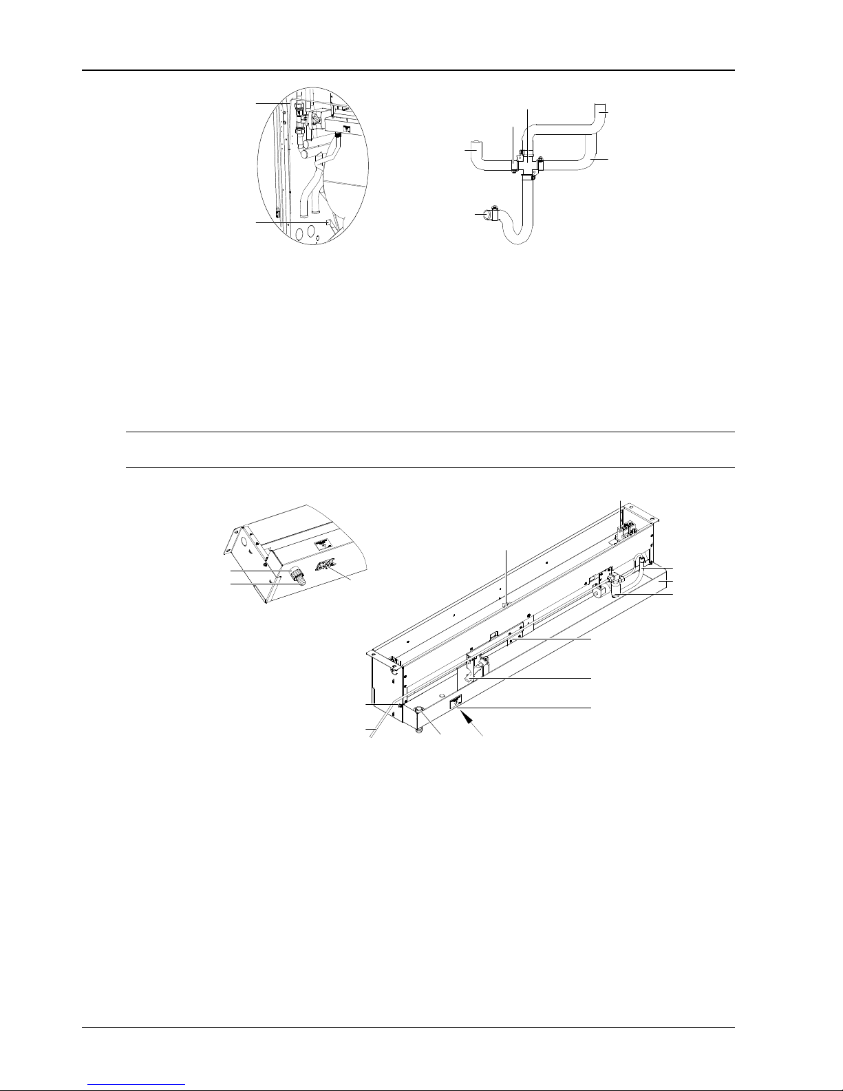
Connecting the water drain-pipe of the unit
The condensing water of infrared humidifier and evaporator is converged by the cross connector and drains
through the drain pipe, as shown in Figure 2-24. The outer diameter (OD) of the pipe is 25mm. If the drain pipe
is used by three or more units, the minimal OD of the pipe should be 40mm.
Note
1. A Φ25 hose clamp is delivered as an accessory to connect the drain pipe.
2. Because the humidifier contains boiling water, the plastic pipe must be rated higher than 194°F.
3. When connecting the drain pipe, make sure that the U bend is installed vertically and the ‘U’ shape is not distorted, so as to
ensure that the cooling water can be drained immediately and effectively.
Page 27
20 Chapter 2 Mechanical Installation
Liebert.PEX Chilled Water Series Air Conditioner User Manual
Infrared humidifier
water in connecting
pipe
Connecting pipe of
condensed water drain
pipe
Condensed water
tray connection
Condensed water
drain pipe connection
Hose clamp
Cross connector
Infrared
humidifier water
tray conncetion
Condensed water
tray connection
Figure 2-24 Connection of water in and out pipes
Connecting water inlet pipe of infrared humidifier
Connect water pipes for the infrared humidifier. To facilitate maintenance, a strainer / non-return isolation
valve is fitted to the supply water pipe. The infrared humidifier reserves a copper pipe (OD: 6.35mm) as shown
in Figure 2-25. 1/4” copper screw nut is put at the end of the copper pipe. Please connect it with the 1/4” × 1/2”
converted copper thread in the attached bag. Connect it with pipes according to the site condition. Make sure
the connection is well sealed to prevent leakage. The pipe pressure is 100kPa ~ 700kPa.
Where the main pressure may rise above 700kPa, a pressure reducer should be fitted. Where the pressure
falls below 100kPa, a water tank and pump system should be used.
Note
Main water supply connections must be made in accordance with local laws and regulations.
A direction
Amplification in A direction
Transport fastener
Water level regulator
Charge
electromagnetic
valve
Water level sensor
Heating over-temperature
protection switch (at the
bottom of water tray)
Charge pipe
Water tray
Heating over-temperature
protection switch
Water out connector
Ceramic terminal base
Overheat protective ralay
Stainless steel
double-screw bolt
Water tray fixing screw
(one at each side)
Water in pipe ODФ 6.35 mm
Φ
Figure 2-25
Infrared humidifier
Connecting chilled water inlet and outlet pipes
The chilled water inlet and outlet pipes are connected with the chilled water unit by welding, as shown in
Figure 2-26. Inlet and outlet pipes should be welded according to the labels on the unit. Please do not reverse
the connection. Chilled water inlet and outlet pipes can be connected through the bottom plate or the side
plate. For the pipe entrance, please refer to Figure 2-13, Figure 2-14 and Figure 2-15. The chilled water inlet
and outlet pipes should have soft connector at the unit connections. The chilled water inlet pipes should be
equipped with the water filter with over 60 meshes to facilitate the clearance of impurities in the pipes. The
chilled water inlet and outlet pipes need to be equipped with several isolation valves, which can cut off water
sources during maintenance. One of the isolation valves can be a balancing valve. Chilled water system with
a balancing valve would be more efficient and more accurate in controlling water distribution. For detailed
distribution, please refer to Figure 2-6.
Water pressure should be able to overcome the water pressure drop caused by all the components of water
system. Considering the possibility that water pressure drop would increase due to incrustation and
impurities resulted from long-time running of the system. Therefore, when choosing the head components
Page 28
Chapter 2 Mechanical Installation 21
Liebert.PEX Chilled Water Series Air Conditioner User Manual
(e.g. pump), we should consider making 20% ~ 25% redundancy. The weight of the water pipes connected
with the unit should not be assumed by the unit. The chilled water inlet and outlet pipes must be kept warm.
Table 2-4 shows the connecting dimensions of chilled water in and out pipes of various units.
Water in pipe
Water out pipe
Water outlet pipe
Water inlet pipe
Figure 2-26 Welding figure of chilled water in and out pipes
Table 2-4 OD of chilled water in and out pipes
Model
OD of chilled water in and out pipes
(mm)
Model
OD of chilled water in and out pipes
(mm)
P1020 32 P2090 42
P1030 32 P2100 42
P1040 32 P3110 54
P1050 32 P3140 54
P2050 42 P3150 54
P2070 42
2.5 Removing Transport Fastener And Vibration Absorber
In order to protect partial components from being damaged and distorted due to bumping, impact and
resonation, fasteners and vibration absorbers are mounted at certain locations before delivery. Remove the
fasteners and vibration absorbers before installation and commissioning.
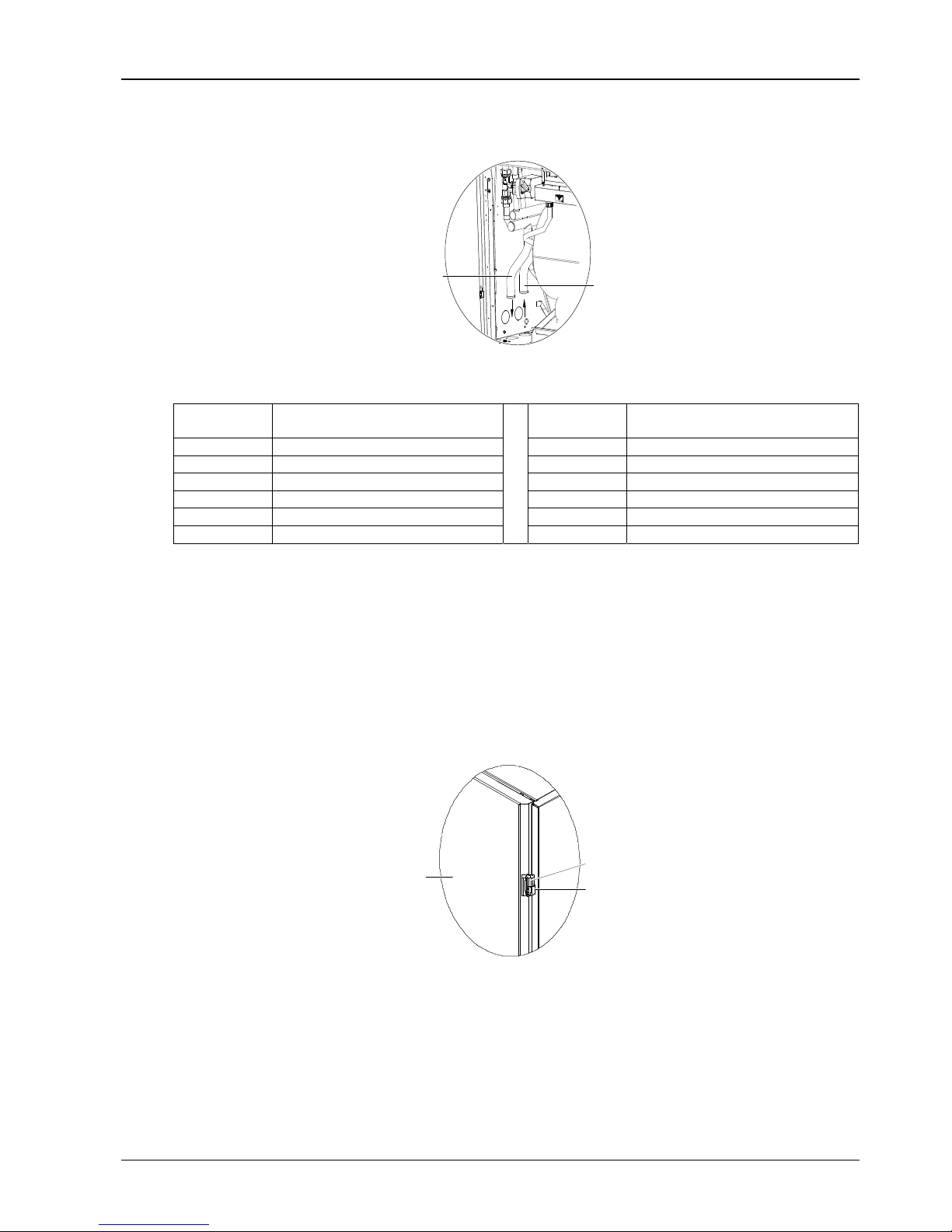
Removing transport binding belt of front door
To protect the front door from moving during transport, tighten the gemel of the front door with binding string.
Before putting the unit into operation, you should cut the binding string. Each front door needs two binding
strings. See Figure 2-27 for their position.
Front door
Binding string
Gemel
Figure 2-27 Binding string of front door
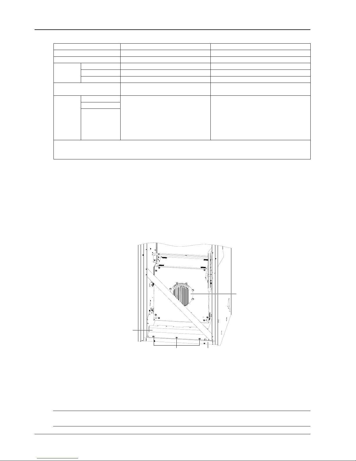
Removing transport fastener of fan components
1. Upflow unit
To minimize the fan operation noise and prolong the belt life, the motor base of the fan is designed with a
semi-free self-tension structure. During transportation, to protect the semi-free structure from failing or
collapsing due to resonation, the upflow unit is especially fastened with sheet metal connector (left and right
symmetrical, one at each side), as shown in Figure 2-28.
Page 29
22 Chapter 2 Mechanical Installation
Liebert.PEX Chilled Water Series Air Conditioner User Manual
You should cut the binding string on the belt and remove the sheet metal connectors on both sides of the
motor before the power-on operation. Removing the sheet metal connectors requires the collaboration of two
persons, with one holding the motor and the other removing the sheet metal connector.
Note
After opening the front door of unit, you will see a warning label concerning the removal of the sheet metal connector on the
sealing panel of the fan. Do remove the sheet metal connector by following the preceding instructions.
Sheet metal connector,
one at each side
Binding string
Figure 2-28 Transportation fan unit binding screw and string
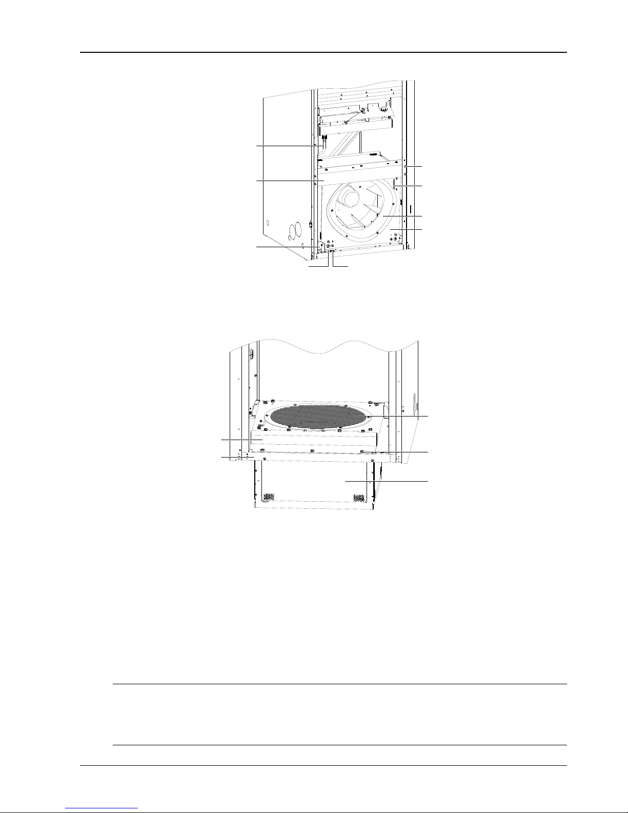
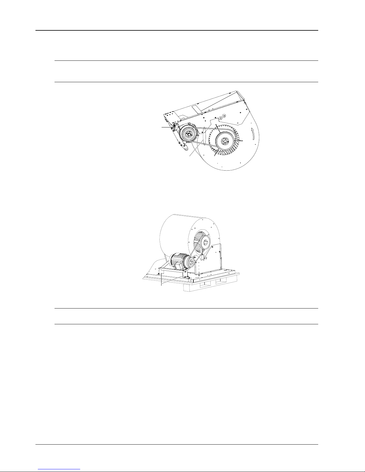
2. Downflow unit
During transportation, to protect the semi-free structure from falling or collapsing due to resonation, the
motor mounting plate is fixed on the bottom plate with connector by bolts, as shown in Figure 2-29. You must
remove the two connectors before the power-on operation.
Sheet metal connector,
one at each side
Figure 2-29 Transportation fan unit binding screw
Note
In any case, never put hands into the triangle gap between the motor installation board and base.
Removing the transport components of infrared humidifier
In order to protect the infrared humidifier lamp from being damaged during transportation, the transport
protection foam should be fitted to the infrared humidifier components. Before operating the unit, check the
protection foam, and connect high water-level detection switch cable. If you operate the unit without
complying with this, the infrared humidifier cannot operate normally and fire may be caused.
Page 30

Chapter 2 Mechanical Installation 23
Liebert.PEX Chilled Water Series Air Conditioner User Manual
Detailed operation procedures are as follows:
1. Cut off the binding wire, and remove the protection foam fixed under the lamp, as shown in Figure 2-30 and
Figure 2-31.
High water-level
test switch cable
Cable tie
Protection foam is at the
bottom of metal sheet
Cable hole of high water-level
test switch cable
Figure 2-30 Removing protection foam 1
保护泡沫
灯管
保护泡沫
Pump
Protecti on
foam
Protecti on fo am
Lamp
Figure 2-31 Removing protection foam 2
2. Remove the four self-tapping screws in the front cover plate of the infrared humidifier connection box, and
then remove the front cover plate, as shown in Figure 2-32.
Remove secf-tapping
screw (4 pcs)
Remove front cover plate
of infrared humidifier
connection box
Remove self-tapping
screw (4 pcs)
Figure 2-32 Opening front cover plate of the connection box
3. Lead the detection switch cable of the high water-level through the cable access hole, as shown in Figure
2-30. Then insert the corresponding cable terminals and the HWA cable terminals in the connecting box, as
shown in Figure 2-33.
Page 31

24 Chapter 2 Mechanical Installation
Liebert.PEX Chilled Water Series Air Conditioner User Manual
HWA cable
Terminal inserting
High water-level test switch cable
Figure 2-33 Connecting the corresponding cable terminals of the high water-level detection
switch and the HWA cable terminal
4. Close the front cover of the infrared humidifier’s connection box, and tighten the self-tapping screw.
5. The infrared humidifier’s high water-level detection switch floating pole and its body have been tightened
with the rubber string in factory, as shown in Figure 2-34. Before operating the unit, remove the rubber string,
otherwise the unit cannot detect and alarm the high water-level.
Rubber string
Floating pole
Figure 2-34 Floating pole of the high water-level sense switch
Remove the rubber string to fix the pipe
To avoid the sheet-metal from damaging the longer copper pipe, the damping foam is used to underlay or
clamp the pipe before it leaves the factory. The foam should be removed and cleaned before commissioning.
2.6 Adjusting Water Level Regulator
The water level regulator of the infrared humidifier is screwed down completely. Before commissioning,
unscrew the water level regulator till its head is 45mm above the water tray bottom, as shown in Figure 2-35.
4
5
4
5
Figure 2-35 Adjusting distance from the water tray
Page 32

Chapter 2 Mechanical Installation 25
Liebert.PEX Chilled Water Series Air Conditioner User Manual
2.7 Installation Inspection
After the mechanical installation is completed, you should check that:
1. A certain space is left around the unit for maintenance. For details, see Maintenance space requirement in
2.3.1 Installation Requirement;
2. The equipment is installed vertically and the installation fasteners have been fixed;
3. The pipes connecting the indoor unit and outdoor unit have been connected;
4. The condensate pump (if needed) has been installed;
5. The drain pipe has been connected;
6. The water supply pipe for infrared humidifier has been connected;
7. All pipe joints have been fixed;
8. The transport fasteners have been removed;
9. The water level regulator of the infrared humidifier has been unscrewed to the required height;
10. The debris (such as transportation materials, structure materials and tools) inside or around the
equipment has been cleaned.
After confirming the preceding points, you can then start the electrical installation.
Page 33

26 Chapter 3 Electric Installation
Liebert.PEX Chilled Water Series Air Conditioner User Manual
Chapter 3 Electric Installation
This chapter introduces the electric installation of the chilled water AC, including the work introduction,
installation notes, wiring of the unit and installation inspection.
3.1 Work Introduction And Installation Notes
Wires to be connected on-site
1. Unit power cables.
2. Unit input and output control cables.
Installation notes
1. The connection of all power cables, control cables and ground cables must comply with local electrician
regulations;
2. See the equipment nameplate for the full load current. The cable sizes should meet the local wiring rules;
3. Mains supply requirement: 380Vac, 50Hz;
4. The electrical installation must be completed by trained personnel;
5. Before the wiring, use a multimeter to measure the power supply voltage and make sure that the power
supply has been switched off.
3.2 Wiring Of Chilled Water AC Unit
3.2.1 Locating Electrical Interfaces
Opening the front door of the chilled water AC unit can reveal the interfaces of electrical control box, as
shown in Figure 3-1, Figure 3-2 and Figure 3-3.
Control interface
N/PE terminal block
Power interface
Upflow
Power interface
Control interface
N/PE terminal block
Downflow
Page 34

Chapter 3 Electric Installation 27
Liebert.PEX Chilled Water Series Air Conditioner User Manual
Figure 3-1 Electrical control box interfaces of one-bay series
Power interface
Control interface
N/PE terminal block
Upflow
Power interface
Control interface N/PE terminal block
Downflow
Figure 3-2 Electrical control box interfaces of two-bay series
Power interface
Control interface
N/PE terminal block
Upflow
Power interface
Control interface N/PE terminal block
Downflow
Figure 3-3 Electrical control box interfaces of three-bay series
3.2.2 Connecting Power Cable Of Chilled Water AC Unit
The power interfaces are located as shown in Figure 3-1, Figure 3-2 and Figure 3-3 and the power interface is
amplified as shown in Figure 3-4. Connect terminals L1, L2, L3, N, and PE to their counterparts of external
power supply. Fix the input cables to the cable clamp located on the right inner side panel, as shown in Figure
3-5. As for the cable specification, see the unit maximum operation current in Table 3-1.
Page 35

28 Chapter 3 Electric Installation
Liebert.PEX Chilled Water Series Air Conditioner User Manual
PEN
L3L2L1
PEN
L3L2L1
PEN
Cable clamp
Figure 3-4 Amplified figure of power interface Figure 3-5 Cable clamp
Note
The cable sizes should meet the local wiring rules.
Table 3-1 Maximum operation current of AC unit
Model Maximum operation current (A)
Model Maximum operation current (A)
P1020 13.1 P2090 23.5
P1030 13.1 P2100 23.5
P1040 13.1 P3110 28.2
P1050 13.1 P3140 28.2
P2050 23.5 P3150 28.2
P2070 23.5
3.2.3 Connecting Control Cables
The control interfaces are located as shown in Figure 3-1, Figure 3-2 and Figure 3-3. The control interface is
amplified in Figure 3-6. The upper part of the terminal block is connected to the AC unit, while the lower part is
used as user control signal interfaces.
Connecting with
smoke sensor, 91# is
its common terminal
Alarm output of
smoke sensor
Connecting
with common
alarm
Short connecting line, no
short line if the remote
shut down is connected
50,51,55 is defined
alarm terminals, 24# is
its common terminal
50,51,52 are defined
Figure 3-6 Wiring of control interfaces
Note
Before connecting the control cables, the wiring personnel must take antistatic measures.
Page 36

Chapter 3 Electric Installation 29
Liebert.PEX Chilled Water Series Air Conditioner User Manual
You can connect the following monitoring and alarm devices.
Remote shutdown (RSD)
Terminals 37 and 38 can be connected to the remote shutdown switch. By default, terminals 37 and 38 are
shorted. Remove the shorting wire if remote shutdown is needed. When terminals 37 and 38 are open, the
system is shut down.
Smoke detect (SDC)
Terminals 91, 92 and 93 can be connected to the smoke sensor, with 91 being the common terminal, 92 being
the NO contact, and 93 being the NC contact. You can select NO or NC contact according to the smoke sensor
logic.
Terminals 80 and 81 are used to output external alarms for the smoke sensor.
Customized alarm terminals
Terminals 50, 51, 55 can be connected to three kinds of sensors, including fire sensor and water sensor.
Terminal 24 is the common terminal. After connecting sensors to the terminals, you should set the
corresponding customized alarm through the microprocessor. See 5.7.6 SET ALARMS for details. When the
contactor is open and there is no external alarm, the input state of the customized terminal is open. But when
the contactor is closed and the external alarm is raised, the input state of the customized terminal will be
shorted. At this time, the system will raise sirens, and the LCD of indoor unit will display the alarm information.
If a PC installed with Emerson monitoring software is connected to the system, the alarm will also be
displayed on the PC.
The terminals can be defined as follows:
Terminals 50 and 24: remote alarm (optional).
Terminals 51 and 24: water sensor (by default).
Terminals 55 and 24: safe switch for condensation water pump (optional).
Water-under-floor sensor (WUF)
Each unit is equipped with one WUF sensor. You should connect one end of the sensor to terminal 51, and the
other end to the common terminal 24. The number of sensors in parallel connection is not limited, but there is
only one water-under-floor alarm for each unit.
Condensing pump safe switch (CPSS)
When the CPSS is configured, you should connect one end of the CPSS to terminal 55, and the other end to
the common terminal 24.
External common alarm terminals
Terminals 75 and 76 can be used as external common alarm terminals. They are controlled by the external
alarm relay K3 on the circuit board. They output signals to external alarm devices, such as the alarm indicator.
When critical alarm occurs, the contactor will close to trigger remote alarms, send signals to the building
management system or dial the paging system automatically. The power supply of the external alarm system
is user self-prepared.
Refer to Appendix 2 Circuit Diagram for the detailed definition of other terminals.
3.3 Installation Inspection
After the electrical installation is completed, you should check and confirm that:
1. The power resource voltage meets the rating on the nameplate.
2. The system electric loop has no open circuit or short circuit.
3. Power cables and grounding cables are connected to the circuit breakers, indoor unit and outdoor unit.
4. The ratings of the circuit breakers and fuses are correct.
5. The control cables are properly connected.
6. All the cable connections are fastened, with no loose screws.
You can start commissioning after confirming the preceding points.
Page 37

30 Chapter 4 System Start-Up Commissioning
Liebert.PEX Chilled Water Series Air Conditioner User Manual
Chapter 4 System Start-Up Commissioning
This chapter introduces the start-up commissioning of the chilled water AC, including preparation before
commissioning, commissioning procedures and inspection after commissioning.
4.1 Locating MCBs
The MCBs are located as shown in Figure 4-1, Figure 4-2 and Figure 4-3.
1234
5
Upflow
1234
5
Downflow
Figure 4-1 MCBs of one-bay series
Page 38

Chapter 4 System Start-Up Commissioning 31
Liebert.PEX Chilled Water Series Air Conditioner User Manual
1234
5
Upflow
1234
5
Downflow
Figure 4-2 MCBs of two-bay series
1234
5
Upflow
1234
5
Downflow
Figure 4-3 MCBs of three-bay series
1: Fan MCB 3: Infrared humidifier MCB 5: Main isolation switch
2: Electrical heater MCB 4: Control board MCB
Page 39

32 Chapter 4 System Start-Up Commissioning
Liebert.PEX Chilled Water Series Air Conditioner User Manual
4.2 Start-Up Commissioning
4.2.1 Preparation Before Commissioning
Mechanical and system part
1. Check that the protection materials during transportation have been removed;
2. Check that the motor pulley and the fan pulley are fixed, the motor bearing and fan bearing are parallel, the
belt is perpendicular to the two bearings and the tension of the belt is proper;
3. The pressure-leak detection of the chilled water system has been done and the chilled water system is
confirmed to be qualified;
4. The cleaning and emptying of the chilled water system have been done (air vent valve is located in the top
of the heat exchanger coil);
5. The chilled water system has been confirmed ready for operation;
6. The water supply-/drainage-pipe system of the humidification system has been reliably connected
according to the material requirements and has been checked against leakage;
7. Make sure the equipment room temperature is above 68°F with sufficient heat load. If the heat load is
insufficient, heat the equipment room with other heating devices, or by forcibly hand-running the heater of the
unit or adjacent other equipment (in this case, go through the following procedures till the third step of 4.2.2
Commissioning Procedures) to make sure the heat load is sufficient for the commissioning.
Electrical part
1. Check that the input voltage of the main power is -10% ~ +15% of the rating;
2. Check that all electrical or control cables are correctly connected. Fasten all the connecting terminals;
3. The power cables and the low voltage control cables are laid away from each other;
4. Check the phase sequence. The phase sequences of all three-phase devices have been adjusted consistent
before delivery. During commissioning, you only need to ensure the phase sequence of a random three-phase
device is correct. In step two of 4.2.2 Commissioning Procedures, you can use a straight screwdriver to click
on the fan contactor within the electric control box to judge the phase sequence by observing the wind
direction. If the phase sequence is wrong, exchange any two phases of the L line of the power supply.
4.2.2 Commissioning Procedures
1. Turn off the MCBs of various parts. Turn on the main MCB and control MCB and check the control voltage.
2. Switch on the fan MCB and click on the contactor of the indoor fan with a screwdriver to confirm the
rotation direction of the fan. Start the equipment and measure all the phase currents of the fan.
3. Switch on the electrical heater MCB and change the temperature setting to start the electric reheat, or start
the heater manually. Measure all the phase currents of electrical heater.
To trigger the electrical heater, you should:
Change the temperature setting (see 5.7 SERVICE MENUS) to 9°F higher than the indoor temperature. The
system should then trigger the call for heating and the electric reheat starts to work. Then set the temperature
setting to 9°F lower than the indoor temperature. If the electrical heater stops working, it means the heating
function is normal. Keeping the temperature setting can make no heating requirement. Continue the following
commissioning steps.
4. Switch on the humidification MCB and change the humidity setting to start the humidifier, or start the
humidifier manually. Measure all the phase currents of the humidifier. Manually charge water into the cooling
system to check that the charge-/drainage-pipes do not leak and the drainage pipes are clear.
To trigger the humidifier, you should:
Adjust the humidity setting (see 5.7 SERVICE MENUS) to 10% higher than the indoor relative humidity. The
control system should then trigger the call for humidification, and the humidifier starts to work. If the
humidifier stops working when the humidity setting is lower than the indoor relative humidity, it means the
humidifying function is normal.
Note
After commissioning, restore the humidity setting to the default or the original setting.
Page 40

Chapter 4 System Start-Up Commissioning 33
Liebert.PEX Chilled Water Series Air Conditioner User Manual
5. Change the temperature setting and start the refrigeration, or start the refrigeration manually. Record the
water flow quantity of the system and water resistance.
To start the refrigeration (open the water flow control valve), you should:
Change the temperature setting (see 5.7 SERVICE MENUS) to 9°F lower than the indoor temperature. The
control system should then trigger the call for refrigeration, and the water flow control valve switches on.
After at least three minutes of refrigeration, change the temperature setting to 9°F higher than the indoor
temperature. If the water flow control valve is closed, it means the refrigeration function is normal.
6. Change the humidity setting and the unit will enter a dehumidifying status. Record the water flow quantity
of the system and water resistance.
To trigger dehumidification, you should:
Change the humidify setting (see 5.7 SERVICE MENUS) to 10% lower than the indoor relative humidity. The
control system should then trigger the call for dehumidification, the water flow control valve switches on.
Note that during the commissioning process, if the indoor temperature is 5.4°F higher than the temperature
setting, the system may enter the forced refrigeration mode, and the dehumidification demand will not be
responded. After commissioning, restore the humidity setting to the default or the original setting.
4.2.3 Inspection After Commissioning
1. Check that all output functions are automatic;
2. Check that the temperature & humidity settings and control precisions are set reasonably;
3. Make sure all the other functions are set reasonably.
Page 41

34 Chapter 5 iCOM Controller
Liebert.PEX Chilled Water Series Air Conditioner User Manual
Chapter 5 iCOM Controller
The iCOM controller adopts menu operation. It can monitor, display and operate the precision cooling air
conditioner and control the environment within a set range. This chapter expounds the LCD, button and
indicator panel, structure chart of control menu, startup interface, main interface, USER MENUS, SERVICE
MENUS, ADVANCED MENUS and EVENT NAME AND DIFINITION of the iCOM controller.
5.1 LCD
An LCD is located on the front panel of the Liebert.PEX2 series air conditioner. The LCD can display the
current state of the equipment room, such as temperature and humidity, and so on. You can also read and
modify the equipment configuration through the LCD.
The LCD uses blue backlight. If no button is pressed within a certain period of time (settable; default: 5min),
the backlight will be off, until the next time any button is pressed.
5.2 Button And Indicator Panel
Nine buttons and two indicators are located on the button and indicator panel, including:
Indicators: alarm indicator and operation indicator.
Buttons: ON/OFF button, enter button, ESC button, up button, down button, left button, right button,
alarm silence button and help button.
The button and indicator panel is shown in Figure 5-1.
Alarm indicator
Alarm silence button
Left button
Up button
Enter button
Right button
Down
button
Help
button
ESC
button
ON/OFF button
Operation indicator
Figure 5-1 Button and indicator panel
The indicators are described in Table 5-1.
Table 5-1 Indicator description
Indicator Description
Alarm indicator The alarm indicator turns on in red upon alarms. It is off after the alarm is cleared
Operation indicator
The operation indicator is on in green when the unit is operating. When the unit is shut down, it
will be on in yellow
Page 42

Chapter 5 iCOM Controller 35
Liebert.PEX Chilled Water Series Air Conditioner User Manual
The functions of the buttons are described in Table 5-2.
Table 5-2 Function description of buttons
Button Function description
ON/OFF
button
1. Switch on/off the system.
Press the ON/OFF button to shut down an operating system, or to start an idle system.
2. Test the display state of the backlight of the LCD and the operation indicator.
After powering-on, when the system is in the standby state (defined as test state in this manual), pressing
the ON/OFF button will switch between the operation indicator (green then) and the LCD backlight. This
function is used to test whether the LCD backlight and the operation indicator are normal
Enter
button
1. Enter the selected menu, or save the setting after parameters are changed. When you are entering a
menu or changing a parameter, the menu and the parameter will be high lighted.
2. Test the display of characters.
When the system is in the test state, pressing the enter button will display the ASCII code. This function is
used to test whether the characters are displayed normally on the LCD
ESC button
1. Quit the current menu.
2. Abolish the current change of parameter.
3. Test the LCD high light.
Pressing the ESC button to switch the LCD between light and high light when the system is in the test
state. This function can test whether the LCD high light is normal
Up button
1. Increase the value of the displayed parameter during parameter setting.
2. Scroll a row or a screen up in the query state.
3. Test the buzzer.
Pressing the up button when the system is in the test state will increase the buzzing frequency (initial
value: 0%). Meanwhile the buzzer will sound at the set frequency. This function is used to test whether the
buzzer is normal
Down
button
1. Decrease the value of the displayed parameter during parameter setting.
2. Scroll a row or a screen down in the query state.
3. Test the buzzer.
If the buzzer frequency is not 0%, pressing the down button when the system is in the test state will
decrease the buzzing frequency. Meanwhile the buzzer will sound at the set frequency. This function is
used to test whether the buzzer is normal
Left button
1. Select the left bit during the parameter setting operation.
2. Test the LCD contrast.
Pressing the left button when the system is in the test state will decrease the LCD contrast (by default:
100%). This function is used to test whether the LCD contrast is normal
Right
button
1. Select the right bit during the parameter setting operation.
2. Test the LCD contrast.
If the LCD contrast is not 100%, pressing the right button when the system is in the test state will increase
the LCD contrast. This function is used to test whether the LCD contrast is normal
Alarm
silence
button
1. The system will issue an alarm sound upon alarms. If you press the alarm silence button, the alarm
sound will be eliminated.
2. Clear the current alarm after the alarm sound is silenced.
3. Test the alarm indicator, and rest the LCD contrast and buzzer frequency.
Pressing the alarm silence button when the system is in the test state will switch the alarm indicator
between on and off. It can test whether the alarm indicator is normal. Meanwhile, reset the LCD contrast to
100% and buzzer frequency to 0%
Help button
1. Display the online help.
2. Test the yellow display of the LCD operation indicator.
When the system is in the test state, pressing the help button will switch on and off the LCD operation
indicator. This function is used to test whether the yellow display of the LCD operation indicator is normal
Note
1. After the system is powered on, the system will assume the operation state before power-off. For example, if the system is in
the work state when it is powered off, it will enter the work state automatically after power-on. You do not need to start it
manually.
2. When the system is in the test state, the setpoints will not be written into the iCOM controller.
Page 43

36 Chapter 5 iCOM Controller
Liebert.PEX Chilled Water Series Air Conditioner User Manual
5.3 Structure Chart Of Control Menu
Please refer to Error! Reference source not found.Error! Reference source not found..
5.4 Startup Interface
After the system is powered on, it is in the waiting state. The LCD will display the interface shown in Figure
5-2.
Figure 5-2 Startup interface
5.5 Main Interface
After power-on, the LCD will enter the main interface after 20s. The main interface provides the general
information of the relative equipment status, including current temperature and humidity, temperature and
humidity setpoints, equipment output status (fan, compressor, cooling, heating, dehumidifying, humidifying),
alarm and maintenance status.
The main interface has two display modes: graphical and simple. The difference between the two display
modes is that the graphic interface (see Figure 5-3) displays the percentage output chart of the function
components while the simple interface (see Figure 5-4) displays the icons of current operation mode only. The
switching of two modes can be realized by operating the menu. For details, refer to 5.6.7 DISPLAY SETUP.
The upper left corner of the main interface displays the current unit number; the upper right corner displays
the current system status. If there is no button operation for 255s on other menu display screen, the LCD
screen will return to the main interface.
20℃ 42%
32℃
43%
100 %
100 %
0%
0%
0%
0%
0%
RCT
UNIT 1
SYS ON
Setting value
Present value
Setpoint
Figure 5-3 Graphical mode of main interface
UNIT
1
SYS ON
20 ℃ 42%
32 ℃ 43%
RCT
S etting v alue
Present value
Setpoint
Figure 5-4 Simple mode of main interface
The icons of the graphical mode and the simple mode on the main interface are defined in Table 5-3.
Table 5-3 Definition of icons
Icon Definition
Icon Definition
Fan running
Free cooling
Cooling
Maintenance
Hot water heating Dehumidifying
Electric heating
Humidifying
Page 44

Chapter 5 iCOM Controller 37
Liebert.PEX Chilled Water Series Air Conditioner User Manual
5.6 USER MENUS
Press the enter or down button on the main interface to enter the USER MENUS, as shown in Figure 5-5. The
USER MENUS are displayed in six pages, each displaying one or two submenus. Press the enter button to
highlight the submenu, the up or down button to browse the submenus, and the enter button to enter the
selected one.
1 / 6
USER MENUS
PASSWORD LEVEL
SETPOINTS
0
C / F
H%R
SET
?
???
2 / 6
USER MENUS
EVENT LOG
GRAPHICS
EVENT
LOG
3 / 6USER MENUS
SET ALARMS
ALARMS
SET
4 / 6
USER MENUS
SENSOR DATA
DISPLAY SETUP
SET
5 / 6
USER MENUS
TOTAL RUN HRS
SLEEP MOOE
6 / 6
USER MENUS
SERUICE INFO
ALARMS
ACTIVE ALARMS
ACTIVE
Figure 5-5 USER MENUS
5.6.1 PASSWORD
The password is necessary for some setpoints. After inputting the password (user password: 149), use the up
button and down button to browse all the options, and then press the enter button to enter the selected one.
5.6.2 SETPOINTS
The setpoints will not be lost when the power fails. You can enter to browse and set the parameters in the
SETPOINTS submenu through the USER MENUS. The left row displays the parameter codes; the middle row,
the parameter name; the right row, the setpoints, as shown in Table 5-4.
Table 5-4 Descriptions of SETPOINTS parameters
Parameters Default Setting range Description
U102 TEMP SET 23°C 5°C ~ 40°C Temperature setpoint
U103 HUM SET 50% 1% ~ 80% Humidity setpoint
U104 HUM CTRL Rel
Pred (predictive), Comp
(compensable), Rel (relative)
Humidity control type
U105 SUP SENS No No, Lim, Ctrl, Cool Supply air type
U106 SUP TEMP 15°C 5°C ~ 25°C Air temperature limit setpoint
U107 BACK TSP 15°C 5°C ~ 40°C Backup temperature setpoints
If you want to modify the preceding setpoints, you should input the password before entering the SETPOINTS
menu. Then press the enter button to highlight it and use the up and down button to scroll the options. Press
the enter button to select one parameter, use the up or down button to set the value, and press the enter
button to save the change.
5.6.3 EVENT LOG
You can enter the EVENT LOG menu without a password, as shown in Figure 5-6.
Page 45

38 Chapter 5 iCOM Controller
Liebert.PEX Chilled Water Series Air Conditioner User Manual
0EVENT LOG P
(01)1/31/2007 10 00
01
Warning
Power loss
:
Figure 5-6 EVENT LOG menu
Page 46

Chapter 5 iCOM Controller 39
Liebert.PEX Chilled Water Series Air Conditioner User Manual
The EVENT LOG menu saves the last 400 system records. The event types include message, warning and
alarm.
When the event type is message, the LCD will display the event name only.
When the event type is warning, the LCD will display the event name and the alarm indicator will turn on
in red.
When the event type is alarm, the LCD will display the event name, the alarm indicator will turn on in red,
and an audible alarm will be raised.
5.6.4 GRAPHICS
The GRAPHICS menu provides two kinds of graphs: RETURN TEMP and RETURN HUMIDITY. These graphs
reflect the temperature and humidity changes over a period of time in the past.
In the graphs, the current temperature or humidity is the origin, the time is the horizontal axis, and the
temperature or humidity is the vertical axis, as shown in Figure 5-7.
RETURN TEMP
01
+03
-03
27
10 40t8d
:
:
°
C
RETURN HUMIDITY
01
+20
-20
+55%
10 42t8d
::
Figure 5-7 The graph of return temperature and return humidity
As the horizontal axis, the time range can be set into eight kinds. Each pixel indicates different time in
different time ranges. See Table 5-5 for the detailed time range.
Table 5-5 Time range
Time range Time indicated by each pixel
Time range Time indicated by each pixel
8min 6s 2d 36min
32min 24s 4d 72min
1hr 45s 8d 144min
12hr 9min 16d 288min
24hr 18min
The scaling of the vertical axis can also be set. For the RETURN TEMP, the scaling range is ±3 ~ ±20; for the
RETURN HUMIDITY, the scaling range is ±10 ~ ±30. The bigger the scaling range is, the bigger the value each
pixel indicates will be, and the more centered the curves will be.
You can set the parameters without inputting the password. Press the enter button to highlight the parameters,
use the up or down button to select one parameter. Then press the enter button again to enter the parameter,
and use the up or down button to set the value. Press the enter button to save the change at last.
5.6.5 SET ALARMS
The SET ALARMS menu is used to set the upper and lower limits of temperature and humidity alarms. The
settings will not be lost when the power fails. You can select the ‘SET ALARMS’ submenu to browse and set
the parameters through the USER MENUS. The parameters are described in Table 5-6.
Note
It is recommended not to change the system defaults. If you consider it necessary to change the defaults, consult professionals
first and set the alarm settings under the guidance of them.
Page 47

40 Chapter 5 iCOM Controller
Liebert.PEX Chilled Water Series Air Conditioner User Manual
Table 5-6 Descriptions of SET ALARMS parameters
Parameters Default Setting range Description
U202 RTN SNSR Yes Yes, No Return air alarm enable
U203 HI TEMP 27°C 1°C ~ 99°C High return air temperature alarm setpoint
U204 LO TEMP 18°C 1°C ~ 99°C Low return air temperature alarm setpoint
U205 HI HUM 60% 1% ~ 99% High return air humidity alarm setpoint
U206 LOW HUM 40% 1% ~ 99% Low return air humidity alarm setpoint
U207 SENSOR A No Yes, No Sensor A alarm enable
U208 HI TEMPA 50°C 1°C ~ 99°C High temperature alarm setpoint of sensor A
U209 LO TEMPA 25°C 1°C ~ 99°C Low temperature alarm setpoint of sensor A
U210 HI HUM A 70% 1% ~ 99% High humidity alarm setpoint of sensor A
U211 LO HUM A 30% 1% ~ 99% Low humidity alarm setpoint of sensor A
U213 SUP SNSR No Yes, No Supply air alarm enable
U214 HI SUP T 24°C 1°C ~ 99°C High supply air temperature alarm setting value
U215 LO SUP T 10°C 1°C ~ 99°C Low supply air temperature alarm setting value
To browse through the menu, press the enter button to highlight the option, and use the up or down button to
scroll.
Password is required for changing the setpoints. Then, enter the SET ALARMS menu, press the enter button
to highlight the option, use the up or down button to browse the submenu. Press the enter button to enter the
selected parameter. Use the up or down button to change the setpoints, and press the enter button to save the
change, or press the ESC button to quit the change.
5.6.6 SENSOR DATA
You can monitor the data acquired by the sensors through the SENSOR DATA menu. The values are read only,
no setting or change is allowed. The parameters are described in Table 5-7.
Table 5-7 Descriptions of SENSOR DATA parameters
Parameters Unit Description
Parameters Unit Description
U301 TEMP A °C Temperature of sensor A U313 Hi Temp °C Daily high temperature
U302 HUM A %
Relative humidity of
sensor A
U314 Lo Te H h
Daily low temperature
(hour)
U303 TEMP B °C Temperature of sensor B U314 Lo Te M m
Daily low temperature
(minute)
U304 HUM B %
Relative humidity of
sensor B
U314 Lo Te S s
Daily low temperature
(second)
U305 TEMP C °C Temperature of sensor C U314 Lo Temp °C Daily low temperature
U306 HUM C %
Relative humidity of
sensor C
U315 Hi Hu H h Daily high humidity (hour)
U307 FC TEMP °C
Free cooling
temperature
U315 Hi Hu M m
Daily high humidity
(minute)
U308 AMB TEMP °C Outdoor temperature U315 Hi Hu S s
Daily high humidity
(second)
U309 FC STATE - Free cooling status U315 Hi Humi % Daily high humidity
U310 DS1 TEMP °C
Temperature of digital
scroll 1
U316 Lo Hu H h Daily low humidity (hour)
U311 DS2 TEMP °C
Temperature of digital
scroll 2
U316 Lo Hu M m Daily low humidity (minute)
U313 Hi Te H hr
Daily high temperature
(hour)
U316 Lo Hu S s
Daily low humidity
(second)
U313 Hi Te M m
Daily high temperature
(minute)
U316 Lo Humi % Daily low humidity
U313 Hi Te S s
Daily high temperature
(second)
Page 48

Chapter 5 iCOM Controller 41
Liebert.PEX Chilled Water Series Air Conditioner User Manual
5.6.7 DISPLAY SETUP
The DISPLAY SETUP menu is used to set the LCD display attributes. Password is not required for changing
the setpoints. The parameters are described in Table 5-8.
Page 49

42 Chapter 5 iCOM Controller
Liebert.PEX Chilled Water Series Air Conditioner User Manual
Table 5-8 Descriptions of DISPLAY SETUP parameters
Parameters Default Setting range Description
U401 LANGUAG EN
RUS, CZE, CHI,
ESP, FRE, ITA,
DEU, EN, POR
Language options
U402 YEAR 2005 - Current year
U402 MONTH 04 01 ~ 12 Current month
U402 DAY 19 01 ~ 31 Current day
U403 HOUR 19h - Current hour
U403 MINUTE 8min - Current minute
U403 SECOND 17s - Current second
U404 TEMP F/C °C °F, °C Temperature indication
U405 CONTRAST 50% 0% ~ 100% Display contract
U406 BUZ FREQ 50% 0% ~ 100% Buzzer frequency. 0% means buzzer silenced
U406 BUZ TEST Off On, Off
Buzzer frequency test switch. It determines whether or not
there will be sound accompanying the adjustment of BUZ
FREQ through the setting
U407 BACKLITE 5min
5min, 10min,
30min, 1hr, 12hr
Backlight time, or the backlight time when there is no button
operation
U408 SCREEN Graph
Graph, Simple,
SimCo, GraCo
Main interface display mode
U409 SHOWS A + S SET, ACT, A + S
Main interface display mode of setpoints and actual values.
Range:
SET: only setpoints of the temperature and humidity are
displayed.
ACT: only actual temperature and humidity are displayed.
A + S: both setpoints and actual values of the temperature
and humidity are displayed
U410 DISPLAY Norm Norm (normal), Inv Display color
U411 DATE m/d/y
m/d/y, d.m.y,
y-m-d
Date display format
5.6.8 TOTAL RUN HRS
The TOTAL RUN HRS menu records the total run time (unit: hr) of the system components. You can also set
the run time limits of the system components through this menu. If the actual component run time exceeds
the set limit, alarms will be raised.
This menu requires password. You can reset the total run time to zero in order to restart timing.
Note
Resetting the timers is not needed unless the components are replaced.
The parameters on this menu are described in Table 5-9. Each component has a LIMIT option to set the run
time limit of the corresponding component.
Table 5-9 Descriptions of TOTAL RUN HRS parameters
Parameters Default Related component
Parameters Default Related component
U502 MOTOR(S) 1000hr
Fan motor
U507 EL HEAT1 34hr
Electric heater 1
U502 LIMIT 32000hr U507 LIMIT 32000hr
U503 COMP1 500hr
Compressor 1
U508 EL HEAT2 45hr
Electric heater 2
U503 LIMIT 32000hr U508 LIMIT 32000hr
U504 COMP2 500hr
Compressor 2
U509 EL HEAT3 0hr
Electric heater 3
U504 LIMIT 32000hr U509 LIMIT 32000hr
U505 CW/FC 1000hr
Chilled water/free
cooling
U510 HUM 7hr
Humidifier
U505 LIMIT 32000hr U510 LIMIT 32000hr
U506 HG/HW 23hr
Hot gas/hot water
U511 DEHUM 1hr
Dehumidification
U506 LIMIT 32000hr U511 LIMIT 32000hr
Page 50

Chapter 5 iCOM Controller 43
Liebert.PEX Chilled Water Series Air Conditioner User Manual
5.6.9 SLEEP MODE
In the sleep mode, the air conditioner unit can realize auto-on/off. Through the SLEEP MODE menu, you can
set two time zones of the sleep mode, and select the sleep timing mode. The parameters on this menu are
described in Table 5-10.
Table 5-10 Descriptions of SLEEP MODE parameters
Parameters Default Setting range Description
U602 MON No
Yes, No
Sleep mode day, including Monday ~ Sunday. Set the value of
any day to ‘Yes’, and the system will enter sleep mode on that
day every week. This parameter works together with the following
hour and minute settings to designate an exact time
U602 TUE No
U602 WED No
U602 THU No
U602 FRI No
U602 SAT No
U602 SUN No
U605 START 1 0hr
-
Sleep mode start time 1. The first parameter is used to set the
hour of time, and the second one is used to set the minute of time
U605 START 1 0m
U605 STOP 1 0hr
Sleep mode end time 1. The first parameter is used to set the
hour of time, and the second one is used to set the minute of time
U605 STOP 1 0m
U607 START 2 0hr
Sleep mode start time 2. The first parameter is used to set the
hour of time, and the second one is used to set the minute of time
U607 START 2 0m
U607 STOP 2 0hr
Sleep mode end time 2. The first parameter is used to set the
hour of time, and the second one is used to set the minute of time
U607 STOP 2 0m
U609 TIME MOD Auto Auto, Yes, No
Timing mode setting. Range:
Auto: during the system sleep time, if high/low temperature
occurs, the system will resume operation and mask the alarm for
15min. The system will re-enter the sleep mode after the alarm is
cleared
Yes: start sleep mode
No: no sleep mode
U610 TIME TYP S.OFF S.OFF, DEADB Timing mode selection
U611 DEADBAND K 2K ~ 15K Used to set the deadband temperature setting range
5.6.10 SERVICE INFO
The SERVICE INFO menu provides the contact information of customer service personnel. The information is
read only.
5.6.11 ACTIVE ALARMS
The ACTIVE ALARMS menu displays the active alarms of the system. No password is required to query this
menu.
5.7 SERVICE MENUS
Press the right button at the first page of the USER MENUS, and you can enter the SERVICE MENUS, as
shown in Figure 5-8.
The SERVICE MENUS are displayed in five pages. Each page displays one or two submenus. Press the enter
button to highlight the submenus, and use the up or down button to scroll up or down. Press the enter button
to enter the selected submenu.
Page 51

44 Chapter 5 iCOM Controller
Liebert.PEX Chilled Water Series Air Conditioner User Manual
SERVICE MENUS
1 / 5
PASSWORD LEVEL
SETPOINTS
0?
???
C / F
H%R
SE T
SERVICE MENUS
STANDBY
WELLNESS
2 / 5
WELLNESS
SERVICE MENUS
DIAGNOSTICS
SET ALARMS
SERVICE
ALARMS
SET
3 / 5
4 / 5
CALIERATION
NETWORK SETUP
NETWORK
SERVICE MENUS
5 / 5
OPTIONS SETUP
SERVICE INFO
SET
UP
SERVICE MENUS
Figure 5-8 SERVICE MENUS
5.7.1 PASSWORD LEVEL
It is operated by Emerson service personnel.
5.7.2 SETPOINTS
Different from the SETPOINTS in the USER MENUS, the SETPOINTS in SERVICE MENUS has many more
parameters. See Table 5-11 for the parameter descriptions.
Table 5-11 Descriptions of SETPOINTS parameters
Parameters Default Setting range Description
S102 TEMP SET 25°C 5°C ~ 40°C Temperature setpoint
S103
CTRL
TYPE
PI Prop, PI, Intel, No Control type selection
S104 TEMP PB 7K 2.2K ~ 30K
Temperature proportional band setpoint, or the P in PID
control
S105 TEMP INT min - Temperature integration time setpoint, or the I in PID control
S107 AUTOSET Yes Yes, No Autoset enable
S108 TEMP DB 0K 0K~20K Temperature deadband setting range
S109 2ND SETP 23°C 5°C ~ 40°C -
S110 BACK TSP 23°C 5°C ~ 40°C Backup temperature setpoint
S111 HEAT DB 0K 0K~20K Heaters deadband setting range
S113 HUM SET 50% 1% ~ 80% Humidity setpoint
S114 HUM CTRL Pred Comp, Rel, Pred Humidity control type
S115 HUM PB 10% 1% ~ 20% Humidity proportional band
S116 HUM INT 5min - Humidity integration time
S117 HUM DB 0% 1% ~ 50% Humidity deadband setting range
S118 LO LIM 1 k - Dehum/Heat low limit 1
S119 LO LIM 2 -1.7K -5.5K ~ -1.1K Dehum/Heat low limit 2
S124 SUP SENS No No, Lim, Ctrl, Cool Supply air type
S125 SUP TEMP 5°C 5°C ~ 27°C Air supply limit temperature setpoint
S126 SUP TYPE PI Prop, PI, PID, Intel Supply control type
S127 SUP PB 12K 2K ~ 30K Supply proportional band
S128 SUINT 0min 0 ~ 15min Supply integration
S130 SUP DB - 0K~20K Supply deadband
S131 VPULS 5% 0 ~ 10% Valve Pulse
S132 CF0 - 0.01 ~ 100% Cooling filter at 0%
S132 CF100 - 0.01 ~ 100% Cooling filter at 100%
S133 RET CO 0K 0 ~ 10K Return Compensation
S135 AMB TYPE No CONT, EFC, VAL, No DT between Room/Outdoor Type
S136 AMB DT 5°C 0°C ~ 20°C DT between Room Air/Outdoor
S137 FC TYPE No No, CONT, VAL DT between Room/FC Type
S138 FC DT 4.5°C 0°C ~ 20°C DT between Room Air/FC Fluid
S139 MIN CW No Yes, No Minimum CW temperature protection selection
S140 MIN CW 7°C 0°C ~ 20°C Minimum CW temperature value
Page 52

Chapter 5 iCOM Controller 45
Liebert.PEX Chilled Water Series Air Conditioner User Manual
Parameters Default Setting range Description
S141 LOCK FC 0°C 0°C ~ 9°C Lockout FC at FC Fluid below
S142 TRANS CH 2% 0.1 ~ 100% Transition Change
S146 FANSPEED Auto
Auto, Man, ECO, SUP,
DELT
VSD Fanspeed
S147 VSD SET 100% 0 ~ 100% Standard speed of the unit
S148 VSD MIN 60% 0 ~ 100% Minimum speed of the unit
S149 VSD DEH 60% 0 ~ 100% Speed used during dehum
S150 VSD NOP 100% 0 ~ 100% Speed used when CI is active
S151 FF0% 0.2% 0 ~ 100% Fanspeed Change (at 0%)
S151 FF100% 1% 0 ~ 100% Fanspeed Change (at 100%)
S152 FRD 0s 0 ~ 300s Fanspeed Reposition Delay
S153 HAD - - -
S154 HAP 6°C 2°C ~ 30°C Fanspeed P-Band
S155 HAI 5min 0 ~ 15min Fanspeed Integration
S157 SCR TYPE - - -
S158 CO1 ON - - -
S159 CO1 OFF - - -
S160 CO1 TD - - -
S161 CO2 ON - - -
S162 CO2 OFF - - -
S163 CO2 TD - - -
S164 CYCLET - - -
S165 SCR FACT - - -
S166 ACT SCR - - -
5.7.3 STANDBY
The parameters of the STANDBY menu are described in Table 5-12.
Table 5-12 Descriptions of STANDBY parameters
Parameters
Defaul
t
Setting
range
Description
S502 #STANDBY 1 0 ~ 32 Number of standby units
S503 ROTATION Daily
No, Daily,
MON ~ SUN,
M - MON ~ M
- SUN
Rotation frequency setting of the running and standby units. Range:
Daily: rotate once a day.
MON ~ SUN: rotate once a week. The rotation occurs on Monday ~
Sunday of the week. For example, MON means rotation occurs on
Monday of every week.
M - MON ~ M - SUN: rotate once a month. The rotation occurs on
Monday ~ Sunday of the first week of the month. For example, M - MON
means rotation occurs on Monday of the first week of every month
S504 ROT HOUR hr - Used to set the hour of the detailed time while rotation
S505 ROT MIN min - Used to set the minute of the detailed time while rotation
S506 ROT BY 1 1 ~ 8 The unit number for a rotation
S507 DO ROT No Yes, No Perform one rotation
S508 CASCADE No
CO/HE,
Cool, Yes,
No
Cascade function selection. ‘Yes’ corresponds to temperature and
humidity control and ‘no’ corresponds to closing the cascade
S509 STBY HT No Yes, No Whether to start all standby units upon high temperature alarm
5.7.4 WELLNESS
The iCOM controller calculates the bonus and penalty over the equipment maintenance based on the
parameters in the WELLNESS menu and the equipment operation historical data, so as to find out the next
system maintenance time.
Informing the maintenance personnel of the maintenance time makes the air conditioner run in the optimal
mode, which reduces the chances of faults and raises the system reliability.
Page 53

46 Chapter 5 iCOM Controller
Liebert.PEX Chilled Water Series Air Conditioner User Manual
The WELLNESS menu includes nine groups of parameters, including WELLNESS BASICs, and WELLNESS
MOTOR, WELLNESS COMPs, WELLNESS HEATs and WELLNESS HUM. See Table 5-13 ~ Table 5-21 for
detailed parameter descriptions.
WELLNESS BASIC1
Table 5-13 Descriptions of WELLNESS BASIC1 parameters
Parameters Default Setting range Description
S002 FREQ/YR 1pY 0pY ~ 12pY Maintenance frequency every year
S003 BONUS MM 0MM ~ 12MM Bonus setting
S004 PENALTY MM 0MM ~ 12MM Penalty setting
S005 LAST PM YY
-
Last maintenance. Year (YY), month (MM) and day (DD). This
parameter is read only
S005 LAST PM MM
S005 LAST PM DD
WELLNESS BASIC2
Table 5-14 Descriptions of WELLNESS BASIC2 parameters
Parameters Default
Setting
range
Description
S006 NAME - - Service personnel setting
S007 CONFIRM No Yes, No Maintenance confirmation selection
S008 NEXT PM - - Calculated next maintenance. This parameter is read only
WELLNESS MOTOR
Table 5-15 Descriptions of WELLNESS MOTOR parameters
Parameters Default Description
S013 STARTS - Number of fan starts since the last maintenance
S014 RUN HRS hr Fan run hours since the last maintenance
S015 AVG RUN min Average fan run time calculated through number of fan starts and run hours
S016 BEST 1 Starts per day best
S017 WORST 24 Starts per day worst
S018 ALARMS 0 Number of alarms since the last maintenance
S019 BONUS 0MM
Bonus amount. Actual bonus calculated through the number of starts and average
run time. This value determines the time for the next maintenance
WELLNESS COMP1
Table 5-16 Descriptions of WELLNESS COMP1 parameters
Parameters Default Description
S024 STARTS - Number of compressor 1 starts since the last maintenance
S025 RUN HRS hr Compressor 1 run hours since the last maintenance
S026 AVG RUN min Average compressor 1 run time calculated through the number of starts and run hours
S027 BEST 12 Starts per day best
S028 WORST 240 Starts per day worst
S029 HP AL 0 Number of high pressure alarms occurred to compressor 1 since the last maintenance
S030 LP AL 0 Number of low pressure alarms occurred to compressor 1 since the last maintenance
S031 OL AL 0 Number of overload alarms occurred to compressor 1 since the last maintenance
S032 DS HT AL 0
Number of digital scroll high temperature alarms occurred to compressor 1 since the
last maintenance
S033 BONUS 0MM
Bonus amount. Actual bonus calculated through the number of starts and average run
time. This value determines the time for the next maintenance
WELLNESS COMP2
Table 5-17 Descriptions of WELLNESS COMP2 parameters
Parameters Default Description
S035 STARTS - Number of compressor 2 starts since the last maintenance
S036 RUN HRS hr Compressor 2 run hours since the last maintenance
Page 54

Chapter 5 iCOM Controller 47
Liebert.PEX Chilled Water Series Air Conditioner User Manual
Parameters Default Description
S037 AVG RUN min Average compressor 2 run time calculated through the number of starts and run hours
S038 BEST 12 Starts per day best
S039 WORST 240 Starts per day worst
S040 HP AL 0 Number of high pressure alarms occurred to compressor 2 since the last maintenance
S041 LP AL 0 Number of low pressure alarms occurred to compressor 2 since the last maintenance
S042 OL AL 0 Number of overload alarms occurred to compressor 2 since the last maintenance
S043 DS HT AL 0
Number of digital scroll high temperature alarms occurred to compressor 2 since the
last maintenance
S044 BONUS 0MM
Bonus amount. Actual bonus calculated through the number of starts and average run
time. This value determines the time for the next maintenance
WELLNESS HEAT1
Table 5-18 Descriptions of WELLNESS HEAT1 parameters
Parameters Default Description
S046 STARTS - Number of electric heater 1 starts since the last maintenance
S047 RUN HRS hr Electric heater 1 run hours since the last maintenance
S048 AVG RUN min
Average electric heater 1 run time calculated through the number of starts and run
hours
S049 BEST 24 Starts per day best
S050 WORST 240 Starts per day worst
S051 ALARMS 0 Number of high pressure alarms since the last maintenance
S052 BONUS 0MM
Bonus amount. Actual bonus calculated through the number of starts and average run
time. This value determines the time for the next maintenance
WELLNESS HEAT2
Table 5-19 Descriptions of WELLNESS HEAT2 parameters
Parameters Default Description
S057 STARTS - Number of electric heater 2 starts since the last maintenance
S058 RUN HRS hr Electric heater 2 run hours since the last maintenance
S059 AVG RUN min
Average electric heater 2 run time calculated through the number of starts and run
hours
S060 BEST 24 Starts per day best
S061 WORST 240 Starts per day worst
S062 ALARMS 0 Number of high pressure alarms since the last maintenance
S063 BONUS 0MM
Bonus amount. Actual bonus calculated through the number of starts and average run
time. This value determines the time for the next maintenance
WELLNESS HEAT3
Table 5-20 Descriptions of WELLNESS HEAT3 parameters
Parameters Default Description
S068 STARTS - Number of electric heater 3 starts since the last maintenance
S069 RUN HRS hr Electric heater 3 run hours since the last maintenance
S070 AVG RUN min
Average electric heater 3 run time calculated through the number of starts and run
hours
S071 BEST 24 Starts per day best
S072 WORST 240 Starts per day worst
S073 ALARMS 0 Number of high pressure alarms since the last maintenance
S074 BONUS 0MM
Bonus amount. Actual bonus calculated through the number of starts and average run
time. This value determines the time for the next maintenance
WELLNESS HUM
Table 5-21 Descriptions of WELLNESS HUM parameters
Parameters Default Description
S079 STARTS - Number of humidifier starts since the last maintenance
S080 RUN HRS hr Humidifier run hours since the last maintenance
Page 55

48 Chapter 5 iCOM Controller
Liebert.PEX Chilled Water Series Air Conditioner User Manual
Parameters Default Description
S081 AVG RUN min Average humidifier run time calculated through the number of starts and run hours
S082 BEST 24 Starts per day best
S083 WORST 240 Starts per day worst
S084 ALARMS 0 Number of high pressure alarms since the last maintenance
S085 BONUS 0MM
Bonus amount. Actual bonus calculated through the number of starts and average run
time. This value determines the time for the next maintenance
5.7.5 DIAGNOSTICS
The DIAGNOSTICS menu is classified into two groups. After entering the menu, pressing the up button and
down button can switch between two groups and pressing the enter button can enter the parameters of the
corresponding group. The parameters of group 1 are settable and used to help the maintenance personnel
start and cut off devices by hand in site, so as to realize the diagnosis for devices. The parameters of group 2
are read only and reflect the fault condition of the devices. See Table 5-22 for detailed descriptions.
Table 5-22 Descriptions of DIAGNOSTICS parameters
Parameters Default
Setting
range
Description
Group 1
S302 HP1 CODE 0 -
HP 1 alarm counting. The counter can be reset to 0
through the parameter
S303 HP2 CODE 0 -
HP 2 alarm counting. The counter can be reset to 0
through the parameter
S304 HT1 CNT 0 -
HT 1 alarm counting. The counter can be reset to 0
through the parameter
S305 HT2 CNT 0 -
HT 2 alarm counting. The counter can be reset to 0
through the parameter
S306 LP1 CODE 0 -
LP 1 alarm counting. The counter can be reset to 0
through the parameter
S307 LP2 CODE 0 -
LP 2 alarm counting. The counter can be reset to 0
through the parameter
S308 LP1 ACT br - Actual LP 1
S309 LP2 ACT br - Actual LP 2
S310 LP1 ACT br - Actual LP 1
S311 LP2 ACT br - Actual LP 2
S313 MANUAL No Yes, No
Selecting ‘Yes’ can turn on or off the components;
selecting ‘No’ can prohibit manual setting
S314 MOTOR(S) On On, Off
Diagnosis switch of fan motor. The settings ‘On’ and ‘Off’
are used to manually start and shut down the fan
respectively
S315 COMP1 Off On, Off
Diagnosis switch of compressor 1. The ‘On’ setting of this
parameter can start compressor 1 only when the fan has
been started
S315 C1 MODE Run
Run, Evac,
Charg
Compressor 1 operation mode selection
S316 C1 CAP Off On, Off
Refrigeration capacity output of digital scroll compressor
1
S317 C1 CYCLE 0% - -
S318 LLSV 1 Off On, Off Diagnostic of liquid line solenoid valve of compressor 1
S319 COMP2 Off On, Off
Diagnostic swtich of compressor 2. Note that the On
setting of this parameter can start compressor 2 only
when the fan has been started
S319 C2 MODE Run
Run, Evac,
Charg
Compressor 2 operation mode selection
S320 C2 CAP Off -
Refrigeration capacity output of digital scroll compressor
2
S321 C2 CYCLE 0% - -
S322 LLSV2 Off On, Off
Diagnosis switch of liquid line solenoid valve of
compressor 2
S324 EL HEAT1 Off On, Off.
Diagnosis switch of electric heater 1. The ‘On’ setting of
this parameter can start electric heater 1 only when the
Page 56

Chapter 5 iCOM Controller 49
Liebert.PEX Chilled Water Series Air Conditioner User Manual
Parameters Default
Setting
range
Description
air loss is normal
S325 EL HEAT2 Off On, Off.
Diagnosis switch of electric heater 2. The ‘On’ setting of
this parameter can start electric heater 2 only when the
air loss is normal
S326 EL HEAT3 Off On, Off.
Diagnosis switch of electric heater 3. The ‘On’ setting of
this parameter can start electric heater 3 only when the
air loss is normal
S327 SCR HEAT - 0 ~ 100 % SCR Heat
S328 DEHUMl Off On, Off Diagnostic switch of Dehumidification solenoid valve
S329 HUM FILL Off On, Off
Diagnosis switch of solenoid valve of water supply to the
humidifier
S330 HUM Off On, Off
Diagnosis switch of humidifier. The ‘On’ setting of this
parameter can start the humidifier only when the air loss
is normal
Group 1
S331 H DRAIN - On, Off Humidfier drain
S332 HUM.C. 0.00A - Electric current of humidifier
S335 ALM REL Off On, Off Diagnostic switch of alarm relay.
S336 K11 REL - On, Off Diagnostic switch of free cooling relay.
S337 3P1 OPEN Off On, Off
Diagnostic switch of 3-phase electric regulator.
S337 3P2 OPEN Off On, Off
S338 3P1 CLOSE Off On, Off
S338 3P2 CLOSE Off On, Off
S339 BV CTRL - Man, Auto Ball valve control type
S340 MBV1 POS - 0 ~ 100%
MBV1 position, MBV2 position
S340 MBV2 POS - 0 ~ 100%
S341 ANALOG1 0% 0 ~ 100%
Diagnostic output of analog variable 1 ~ 4. They can be
set to be percentage of desired output
S342 ANALOG2 0% 0 ~ 100%
S343 ANALOG3 0% 0 ~ 100%
S344 ANALOG4 0% 0 ~ 100%
Group 2
S345 RSD On On, Off Remote shut down. Range: On, Off
S346 AIR LOSS OK OK, ACT
Air loss alarm. OK means the system is normal. ACT
means the air loss is active, and abnormity occurred
S347 MOTOR OL ACT OK, ACT
Fan motor overload alarm. OK means the fan is normal.
ACT means the fan is overloaded, and abnormality
occurred
S348 FILTER OK OK, ACT
Filter clogging situation. OK means normal; ACT means
the filter is clogged
S349 CUSTOM1 OK OK, ACT
States of customized alarms 1 ~ 4. ‘OK ‘means normality;
‘ACT’ means that the alarm is active and that abnormality
occurs
S350 CUSTOM2 OK OK, ACT
S351 CUSTOM3 Ok OK, ACT
S352 CUSTOM4 OK OK, ACT
S353 HEAT SAF OK OK, ACT Status heaters safety
S354 FLOW AT % - -
S355 FLOW ACT % - -
S356 HP1 OK OK, ACT
State of high pressure switch 1. OK means normal. ACT
means abnormal
S357 LP1 OK OK, ACT
State of low pressure switch 1. OK means normal. ACT
means abnormal
S358 C1 OL OK OK, ACT
Overload state of compressor 1. OK means normal. ACT
means abnormal
S359 HP2 OK OK, ACT
State of high pressure switch 2. OK means normal. ACT
means abnormal
S360 LP2 OK OK, ACT
State of low pressure switch 2. OK means normal. ACT
means abnormal
S361 C2 OL OK OK, ACT
Overload state of compressor 2. OK means normal. ACT
means abnormal
S367 HUM PROB OK OK, ACT
Humidifer fault state. OK means normal. ACT means
abnormal
S368 DT1 - OK, ACT Status DT1 (Outdoor/Glycol)
S369 DT2 - OK, ACT Status DT2 (Glycol/Room)
Page 57

50 Chapter 5 iCOM Controller
Liebert.PEX Chilled Water Series Air Conditioner User Manual
Parameters Default
Setting
range
Description
S370 DT3 On On, Off Status DT3 (Room/Setpoint)
S371 MIN CW - OK, ACT Status Min CW
S372 LWD Val - - -
S374 LSI - - -
S375 COND 2 - - -
S376 COND 1 - - -
S379 V_CTRL Time Time, Feedb Valve Control
S380 V_CAL No Yes. No Start Valve Calibration
S381 CAL_STAT Idle - -
S382 CLSD 1 - - -
S383 OPEN 1 - - -
S384 V1FDB - - -
S385 CLSD 2 - - -
S386 OPEN 2 - - -
S387 V2FDB - - -
5.7.6 SET ALARMS
The SET ALARMS menu is displayed in nine pages. The first page provides the settings of alarm upper/lower
limits and customized alarms. The other eight pages provide the settings of alarm delay.
Alarm upper/lower limits setting
The alarm upper/lower limits in the SERVICE MENUS are set the same as those in the USER MENUS. For
details, see Table 5-6.
Customized alarms setting
See Table 5-23 for the descriptions of customized alarms setting.
Table 5-23 Descriptions of customized alarms setting
Parameters Default Parameters Default
S202 RTN SNSR Yes S215 LO SUP 10°C
S203 HI TEMP °C S224 CUST IN1 WATER
S204 LO TEMP °C S225 C1 ACT CLOSE
S205 HI HUM 60% S226 CUST IN2 WATER
S206 LOW HUM 40% S227 C2 ACT CLOSE
S207 SENSOR A No S228 CUST IN3 WATER
S208 HI TEMP A °C S229 C3 ACT CLOSE
S209 LO TEMP A °C S230 CUST IN4 HEAT A
S210 HI HUM A % S231 C4 ACT OPEN
S211 LO HUM A % S232 WA AC AL No
S213 SUP SNSR No S233 WAT OFF No
S214 HI SUP T 24°C
CUST IN1, CUST IN2, CUST IN3 and CUST IN4 can be set to 21 types of input. See Table 5-24 for details.
Table 5-24 Descriptions of types
Types Description Types Description Types Description
SMOKE Smoke alarm RH+HU Rht + Hum lockout RJTVS HTRJ TVSS
WATER Water leakage alarm COMP Compressor lockout Fire Fire Alarm
C PMP Cooling pump alarm Call Call for service 2.Set 2nd Setpoint
FLOW Insufficient water alarm Temp High temperature alarm NoP No Power
G PMP Standby pump alarm Air Air loss alarm LSI LSI
STBY Standby unit alarm FC L. FC lockout Cnd 1 Condensor 1 Fail
C-In1 Customized alarm 1 HeatA Heater alarm Cnd 2 Condensor 2 Fail
C-In2 Customized alarm 2 FLOSD Flow AL SD ScRed D-Scroll Red
C-In3 Customized alarm 3 FLOLC Flow AL LC Swap V Swap Valve
C-In4 Customized alarm 4 ComPD Comp Lock PD ECFan EC Fan Fail
RHT Reheater lockout En FC Enable FC,
HUM Humidifier lockout RJVFD HTRJ VFD
Page 58

Chapter 5 iCOM Controller 51
Liebert.PEX Chilled Water Series Air Conditioner User Manual
C1 ACT, C2 ACT, C3 ACT and C4 ACT correspond to the customer alarms. ‘OPEN’ means normally open,
‘CLOSE’ means normally closed.
Alarm delays setting
The alarm delays are the time after faults occur and before the alarms are triggered. See Figure 5-9 for the
menu format.
2/10
S236
S237
S238
S239
S240
S241
FOL
LOA
CF
HRT
LRT
HRH
DEL EN
T
5
3
2
30
30
30
Yes
Yes
Yes
Yes
Yes
Yes
ALM
ALM
WRN
WRN
WRN
WRN
01SET ALARMS
Figure 5-9 Alarm delay
The alarm name, delay time, delay enabling and alarm type are displayed from left to right in the list.
The alarm delay can be set to 0 ~ 9999. Unit: second.
The delay enabling determines whether the alarm will be displayed and the alarm menu is entered, Options
include ‘Yes’ and ‘No’.
The alarm type can be set to ‘ALM’ (alarm), ‘WRN’ (warning) and ‘MSG’ (message). They determine the alarm
degree of the corresponding event.
The alarm names are listed in Table 5-25.
Table 5-25 Alarm name description
SN
Alarm/event
name
Description
SN
Alarm/event
name
Description
S236 FOL Fan overload S266 LOF Loss of flow
S237 LOA Loss of airflow S267 SGP Standby glycol pump on
S238 CF Filter clogged S268 STB Standby unit on
S239 HRT High room temp. S269 HUP Humidifier problem
S240 LRT Low room temp. S270 NOC No connection w/Unit1
S241 HRH High room hum. S271 - No connection w/UnitX
S242 LRH Low room hum. S272 LOP LOSS OF POWER
S243 HTA High temperature of sensor A S275 CI1 Customized input 1
S244 LTA Low temperature of sensor A S276 CI2 Customized input 2
S245 HHA High humidity of sensor A S277 CI3 Customized input 3
S246 LHA Low humidity of sensor A S278 CI4 Customized input 4
S249 OL1 Compressor 1 overload S279 CS Call for service
S250 OL2 Compressor 2 overload S280 HTD High temperature
S251 HP1 Compressor 1 high pressure S281 LB1 Loss of air blower 2
S252 HP2 Compressor 2 high pressure S282 RL Reheat lockout
S253 LP1 Compressor 1 low pressure S283 HL Humidifier lockout
S254 LP2 Compressor 2 low pressure S284 FCL FC lockout
S255 PD1
Compressor 1 pumpdown
fails
S285 CL Compressor(s) lockout
S256 PD2
Compressor 2 pumpdown
fails
S288 SC1 Short cycle 1
S257 HT1
Digital scroll 1 high
temperature
S289 SC2 Short cycle 2
S258 HT2
Digital scroll 2 high
temperature
S290 NOP NO power
S259 EHO EL HEAT HIGH TEMP S291 CN1 Condensor 1 Fail
S262 WHE Working hours exceeded S292 CN2 Condensor 2 Fail
S263 SMO Smoke detected S293 EFF EC Fan fail
S264 WUF Water under floor S294 HST High supply air temperature
S265 CPH Conderser pump high water S295 LST Low supply air temperature
Page 59

52 Chapter 5 iCOM Controller
Liebert.PEX Chilled Water Series Air Conditioner User Manual
5.7.7 CALIBRATION
The CALIBRATION menu can calibrate sensors by setting offsets. The parameters are listed in Table 5-26. The
parameters are in pairs: the former is the calibrated value and the latter is the calculated value, or the sum of
the measured value and the calibrated value. This value is engaged in the calculation of control need.
Table 5-26 Descriptions of CALIBRATION parameters
Parameters Default Description
S602 RTN TEMP K
Calibrated return air temperature. It can be set as a positive or negative value. Use
the up and down buttons to change the setting value, 0.1K at each step
S603 CAL TEMP 25°C
Sum of the calibrated value and measured return air temperature. This value is
compared with the setting value as the system actual temperature and is engaged in
the calculation
S604 RTN HUM +0.0%
Calibrated return air humidity. It can be set as a positive or negative value. Use the
up and down buttons to change the setting value, 1% at each step
S605 CAL HUM 44.0%
Sum of the calibrated value and measured return air humidity. This value is
compared with the setting value as the system actual humidity and is engaged in
the calculation
S606 DS1 NTC +0.0K
Calibrated digital scroll 1NTC. It can be set as a positive or negative or positive
value. Use the up and down buttons to change the setting value, 0.1K at each step
S607 CAL DS1 29°C
Sum of the calibrated value and return air humidity measured by digital scroll 1NTC
sensor. This value is engaged in the calculation
S608 DS2 NTC +0.0K
Calibrated digital scroll 2NTC. It can be set as a positive or negative value. Use the
up and down buttons to change the setting value, 0.1K at each step
S609 CAL DS2 25°C
Sum of the calibrated value and return air humidity measured by digital scroll 2NTC
sensor. This value is engaged in the calculation
S610 OUT SNS °C Outdoor Sensor
S611 CAL OUT +0.0K Calibrated Outdoor Sensor
S613 TEMP A +0.0K Calibrated value of temperature sensor A
S614 CAL A °C Calculated value corresponding to temperature sensor A
S615 HUM A +0.0% Calibrated value of humidity sensor A
S616 CAL A 44.0% Calculated value corresponding to humidity sensor A
S617 TEMP B TH Calibrated value of temperature sensor B
S618 TYPE B +0.0K Type of temperature sensor B
S619 CAL B °C Calculated value corresponding to temperature sensor B
S620 HUM B +0.0% Calibrated value of humidity sensor B
S621 CAL B 44.0% Calculated value corresponding to humidity sensor B
S622 TYPE C TH Type of temperature sensor C
S624 FC SNSR -
Free cooling temperature sensor. PTC or NTC sensor can be configured according
to the actual configuration
S625 FC SNSR +0°C Calibrated value of free cooling temperature sensor
S626 CAL FC °C Calculated value of free cooling temperature sensor
S627 SUP SNSR NTC Air supply temperature sensor. PTC or NTC sensor can be configured
S628 SUP TEMP +0.0K Calibrated value of air supply temperature sensor
S629 CAL SUP °C Calculated value of air supply temperature sensor
S630 TEMP C +0.0K Calibrated value of temperature sensor C
S631 CAL C °C Calculated value of temperature sensor C
S632 HUM C +0.0% Calibrated value of humidity sensor C
S633 CAL C % Calculated value of humidity sensor C
5.7.8 NETWORK SETUP
The NETWORK SETUP menu is used to set the parameters when the system is in a network subject to the
monitoring of a host. See Table 5-27 for parameter descriptions.
Table 5-27 Descriptions of NETWORK SETUP parameters
Parameters Default
Setting
range
Description
S802 #UNITS 1 1 ~ 32 Range: 1 ~ 32
S803 TEAMWORK No No, 1, 2 Range: No, 1, 2
Page 60

Chapter 5 iCOM Controller 53
Liebert.PEX Chilled Water Series Air Conditioner User Manual
Parameters Default
Setting
range
Description
S824 MON ADD 3 1 ~ 99 Monitoring address No. of the unit
S825 MON T.O. No No, 1, 2 Monitoring Timeout
S825 MON H.S. 3 1 ~ 99 Monitoring Handshake
S831 CS CTRL No
Save, Load,
No
Save the parameter set through MON ADD to the iCOM
controller. ‘No’ means not saved
S831 CS STAT Change
Change,
Valid
Indication of the saving state of the parameter set through MON
ADD. ‘Change’ means that the parameter is changed but not
saved. ‘Valid’ means that the setting is valid and saved
S832 NW CTRL No
Save, Load,
No
Save the parameter set through U2U GRP to the iCOM
controller. ‘No’ means not saved
S832 NW STAT Valid
Change,
Valid
Indication of the saving state of the parameter set through U2U
GRP. ‘Change’ means that the parameter is changed but not
saved. ‘Valid’ means that the setting is valid and saved
S835 MON PROT Vlcty
Vlcty, HN,
IGM, No
Host monitoring protocol setting. Range: Vlcty (Velocity uses
intelligent card), HN (Hironet), IGM (ECA2), No
S836 IP #1 192
- Set IP address
S836 IP #2 168
S836 IP #3 254
S836 IP #4 1
S837 NM #1 255
- Set subnet mask
S837 NM #2 255
S837 NM #3 255
S837 NM #4 0
S838 GW #1 0
- Set gateway address
S838 GW #2 0
S838 GW #3 0
S838 GW #4 0
S840 U2U PROT GBP - -
S841 U2U ADD 3 - Group address No. of this unit
S842 U2U GRP 1 - -
S843 BL CTRL No S + R, No
Boot program variant load. Saving the change of S835 ~ S841
needs the S + R command of this parameter. The system will
reset after the saving, and configure according to the new
parameters
S843 BL STAT Change
Change,
Valid
Indication of whether or not the parameters set through S835 ~
S841 are saved. ‘Change’ means that the parameter is changed
but not saved. ‘Valid’ means that the setting is valid and saved
S844 SR CTRL No C + R, No
Static RAM data reset control. If the change of S835 ~ S841 are
not saved, using the C + R command in this parameter can
restore S835 ~ S841 to their original settings, and the system
will reset afterwards
S844 SR STAT Valid - STD
SW# - - Version No. of the control software
MAC
00:00:68:19:
31:70
00:00:68:19:3
1:70
MAC address of the network card of the iCOM controller
NAME UNIT UNIT
Name of the unit. By default: UNIT. You can change the name as
you need
5.7.9 OPTIONS SETUP
The OPTIONS SETUP menu is used to set the parameters according to the equipment-specific demands. See
Table 5-28 for detailed descriptions.
Table 5-28 Descriptions of OPTIONS SETUP parameters
Parameters Default Setting range Description
S402 COMP SEQ Auto
Auto, 1
(compressor 1
being the
Compressor sequence. Range: Auto, 1 (compressor 1 being the
primary one), 2 (compressor 2 being the primary one)
Page 61

54 Chapter 5 iCOM Controller
Liebert.PEX Chilled Water Series Air Conditioner User Manual
Parameters Default Setting range Description
primary one), 2
(compressor 2
being the
primary one)
S403 LP DELAY 1min - Low pressure alarm delay
S405 EL HEAT 1 0 ~ 3 Electric heating stages
S406 EL HEAT C - - -
S407 HW HEAT No Yes, No Hot water heating enabled
S408 ALL HEAT 3 0 ~ 3 heating stages.
S409 LWDconn No Yes, No
LWD connected. Range: Yes (water low sensor connected), No
(water low sensor not connected)
S409 V_CTRL Time Time, Feedback -
S410 3P RUN 165s - 3P actuator runtime
S411 3P DIR DIR DIR, REV 3P actuator direction
S413 HUM ENAB Yes Yes, No Humidification enabled
S414 IR FLUSH 150% - Infrared flush rate
S415 HUMSTEAM % - -
S416 HUM CONT On, Off On, Off, Prop Humidifier control mode
S417 HUM.TIME s - Humidifier bottle flush time
S418 HUM.MAN Yes Yes, No Humidifier bottle manual flush enabled
S419 DEHUM EN Yes Yes, No Dehumidification enabled.
S420 REST EN Yes Yes, No Auto restart enabled
S421 RESTART s - Unit auto restart time
S422 ONOFF EN Yes Yes, No
On-off key enabled. If “no” is selected, the ON/OFF key cannot
be used to perform on/off operation on the machine.
S424 CW FLUSH 0hr - Cooling water auto flush time, unit: hr (hour)
S425 FC FLUSH 0hr - Free cooling auto flush time, unit: hr (hour)
S426 HT FLUSH 0hr - Hot water auto flush time, unit: hr (hour)
S427 BALL OFF +0.0br - -
S428 HEAT AS - - -
S429 CW_CTRL - - -
S430 MAIN V - - -
S431 VALV ROT - - -
S432 VALV TIM - - -
S433 DEHUM OP - - -
5.7.10 SERVICE INFO
The SERVICE INFO menu provides the contact information of maintenance personnel. The maintenance
personnel can input and save their contact information through this submenu.
5.8 ADVANCED MENUS
The ADVANCED MENUS include PASSWORD LEVEL, FACTORY SETUP and PASSWORDS, as shown in Figure
5-10.
ADVANCED MENUS
1 / 2
PASSWORD LEVEL
FACTORV SETUP
3
????
SET
PASSWORDS
2 / 2
ACCESS
ADVANCED MENUS
Figure 5-10 ADVANCED MENUS
5.8.1 PASSWORD LEVEL
It is operated by Emerson service personnel.
Page 62

Chapter 5 iCOM Controller 55
Liebert.PEX Chilled Water Series Air Conditioner User Manual
5.8.2 FACTORY SETUP
The FACTORY SETUP menu is displayed in nine pages. The parameters are described in Table 5-29 ~ Table
5-38.
Unit code related settings
Table 5-29 Descriptions of unit code related settings
Parameters (1/9) Default Setting range Description
A003 UC 01 0
-
Unit code setting. The code has 18 bits. Each bit can be set as 0
~ 20
… … …
A003 UC 06 0
A005 UC 07 0
… … …
A005 UC 12 0
A007 UC 13 0
… … …
A007 UC 18 0
A008 UC CTRL No
Save, Load,
Compare, No
Options include:
Save: after UC01 ~ UC18 are changed, the changed can be
saved through the save command.
Load: load parameters to the unit code directly.
Compare: compare the present parameters and the parameters
to be loaded.
No: All changes are cancelled. Keep the old parameters
A009 UC STAT OK
Not available,
Invalid, OK,
Changed,
Updating
Unit code status. Range:
Not available: parameters set through UC01 ~ UC18 are
unavailable.
Invalid: parameters set through UC01 ~ UC18 are invalid.
OK: parameters set through UC01 ~ UC18 are effective.
Changed: parameters UC01 ~ UC18 are changed, but not
saved.
Updating: parameters are updating
A010 EL CTRL Load - External data can be loaded through the load command
A011 EL STAT OK
Not available,
Invalid, OK,
Changed,
Updating
Exception list status. Range:
Not available: parameters set through UC01 ~ UC18 are
unavailable.
Invalid: parameters set through UC01 ~ UC18 are invalid.
OK: parameters set through UC01 ~ UC18 are effective.
Changed: parameters UC01 ~ UC18 are changed, but not
saved.
Updating: parameters are updating
System related settings
Table 5-30 Descriptions of system related settings
Parameters (2/9) Default
Setting
range
Description
A102 REFRIG R22
R407C, R22,
R410A
Refrigerant type selection
A103 MOTOR OL SHUTD
SHUTD,
DISAB
Main fan overload. The action to take after the fan overload. Range:
SHUTD (fan shuts down), DISAB (shut down humidifier,
dehumidifier and heater, only keep the cooling unit running)
A104 AIR LOSS SHUTD
SHUTD,
DISAB
The action to take after the loss of airflow. Range: SHUTD (fan shuts
down), DISAB (shut down humidifier, dehumidifier and heater, only
keep the cooling unit running)
A105 # COMP 0 0 ~ 2 Number of compressors
A106 COMP DLY s - Compressor delay time
A107 COMP ON min 0 ~ 5min Compressor minimum on time
A108 COMP OFF 3min 0 ~ 5min Compressor minimum off time
A109 PUMPDOWN Yes Yes, No Pump down enable
Page 63

56 Chapter 5 iCOM Controller
Liebert.PEX Chilled Water Series Air Conditioner User Manual
A110 CAP TYPE No
4step,
HGBP, DS,
DS + TH, No
Capacity control type. 4step: four steps. HGBP: hot gas bypass. DS:
digital scroll. DS + TH: digital scroll and temperature switch. No:
with no need for capacity control type
A111 FLOCT 0s 0 ~ 180s Shutdown time of airflow loss
Other settings
Table 5-31 Descriptions of other settings
Parameters (3/9) Default Setting range Description
A113 DS CYCLE s - Digital scroll cycle
A114 DS HT °C - Digital scroll high temperature
A115 DS SWB °C - Digital scroll switchback
A116 LP TYPE Analog Analog, Digital Low pressure device type
A117 LP PH1 ps - Low pressure threshold phase 1
A118 LP PH2 ps - Low pressure threshold phase 2
A119 LC PRE 0.0s - Liquid control pre-time
A120 LC POST 0.0s - Liquid control post-time
A121 CHARGE P br - Loss of Charge Protection
Page 64

Chapter 5 iCOM Controller 57
Liebert.PEX Chilled Water Series Air Conditioner User Manual
LP sensor related settings
Table 5-32 Descriptions of LP sensor related settings
Parameters (4/9) Default Setting range Description
A124 LP1 LOW 10% 0 ~ 100% LP1 sensor lower threshold (percentage)
A124 LP1 LOW 0bbr 10 ~ 50br LP1 sensor lower threshold
A125 LP1 HIGH 90% 0 ~ 100% HP1 sensor lower threshold (percentage)
A125 LP1 HIGH 10.3br 10 ~ 50br HP1 sensor lower threshold
A126 LP1 ACT - - Actual LP1 signal. Read only
A127 LP2 LOW 10% 0 ~ 100% LP2 sensor lower threshold (percentage)
A127 LP2 LOW 0br 10 ~ 50br LP2 sensor lower threshold
A128 LP2 HIGH 90% 0 ~ 100% HP2 sensor lower threshold (percentage)
A128 LP2 HIGH 10.3br 10 ~ 50br HP2 sensor lower threshold
A129 LP2 ACT - - Actual LP2 signal. Read only
A130 PD CUT br - Pumpdown cutout
A131 PD RECYC br - Pumpdown recycle
A132 HEAT REJ W/G
FSC, L-T,
W/G
Heat rejection control. Range:
FSC: fan speed control; L-T: Lee-Temp; W/G: water/glycol cooling
Free-cooling, HG and HW related settings
Table 5-33 Descriptions of free-cooling, HG and HW related settings
Parameters (5/9) Default Setting range Description
A135 K11 ACT DEH
WNG、DEH、NOP、FC
-
A136 C/W F DUR 3min 1min ~ 3min Cooling water flush duration
A137 COOL TYP SINGL Singl, FC, DC Three cooling type
A138 STOP FC+ °C - Stop FC at setpoint + or value
A139 FC F DUR 0min 1min ~ 3min Freecooling flush duration
A140 FC F K11 Yes Yes, No Freecooling flush starts R5
A141 COMP + FC No Yes, No Compressor plus FC simultaneously
A142 HW F DUR 3min 0 ~ 3min Hot water flush duration
A143 HG HEAT No Comp.1, Comp.2, No Hot gas heating enabled
A144 HEAT OP STAGE Stage, Delay, No Electric heater operation mode
Humidification and dehumidification related settings
Table 5-34 Descriptions of humidification and dehumidification related settings
Factory 6/9 Default Setting range Description
A146 HUM TYPE IFS
External, IFS, IFL,
PEX6, PEX9, PEX12,
21LLA, 53LLC,
53HLB, 93LLE,
93HLD, d3H, HT2,
HT5, HT9, SGH, No
Humidifier model
A147 HUM VOLT V - -
A148 HUM LAST 15hr -
Detect whether the last operation time exceeds this
cycle setting during the startup of the humidifier. Unit:
hr
A149 PREFILL 30s or 57s - Prefill time. Unit: second
A150 FILL 57s - Fill time. Unit: second
A151 HUM ON 584s - Humidifier on time. Unit: second
A152 DEH COMP 1 1, 2, both
Dehumidification with compressor. When 1 or 2 is
selected, compressor 1 or 2 is used for
dehumidification. When Both is selected, the two
compressors are both used for dehumidification
Page 65

58 Chapter 5 iCOM Controller
Liebert.PEX Chilled Water Series Air Conditioner User Manual
Analog output related settings
Table 5-35 Descriptions of analog output related settings
Factory 7/9 Default Setting range Description
A157
ANOUT1LO 0% 0 ~ 100%
-
A157
ANOUT1HI 100% 0 ~ 100%
A158
ANOUT2LO 0% 0 ~ 100%
A158
ANOUT2HI 100% 0 ~ 100%
A159
ANOUT3LO 0% 0 ~ 100%
A159
ANOUT3HI 100% 0 ~ 100%
A160
ANOUT4LO 0% 0 ~ 100%
A160
ANOUT4HI 100% 0 ~ 100%
A161
FS HE/HU 100% 0 ~ 100%
A163
ANOUT1 No -
Analog output selection. See Table 5-36
A164
ANOUT2 No -
A165
ANOUT3 No -
A166
ANOUT4 No -
Table 5-36 Descriptions of analog output options
Options Description
Options Description
CW010 CW/FC 0 ~ 10V ALBD2 AlarmBoard 2
HW Hot water ALBD3 AlarmBoard 3
HW175 Hot water 1.75 IVAR I-Variex 1
VSD Variable fan speed drive HUM% HT HUM
COOL Cooling SUP Supply Temperature
CV175 CW/FC 1.75 RET Return Temperature
COOL1 Cooling 1 HUMI Humidifier
COOL2 Cooling 2 SUPSA Supersaver
HEAT Heater INVCO Inverted Cool
No No use HEAT3 Heating 33%
MBV1 Motorized ball vavle1 CW210 CW/FC 2V ~ 10V
MBV2 Motorized ball vavle 2 C2010 CW2 0 ~ 10V
SCR Silicon controlled rectifier C2175 CW2 1.75
CONF Configurable C2210 CW2 2 ~ 10V
ALBD1 AlarmBoard 1
Analog action related settings
Table 5-37 Descriptions of analog action related settings
Parameters (8/9) Default Setting range Description
A168 AO1 STA 0% 0% ~ 100% Analog output 1 start percentage
A168 AO1 STA 0V 0V ~ 10V Analog output 1 start voltage
A169 AO1 END 100% 0% ~ 100% Analog output 1 end percentage
A169 AO1 END 10V 0V ~ 10V Analog output 1 end voltage
A170 AO2 STA 0% 0% ~ 100% Analog output 2 start percentage
A170 AO2 STA 0V 0V ~ 10V Analog output 2 start voltage
A171 AO2 END 100% 0% ~ 100% Analog output 2 end percentage
A171 AO2 END 10V 0V ~ 10V Analog output 2 end voltage
A172 AO3 STA 0% 0% ~ 100% Analog output 3 start percentage
A172 AO3 STA 0V 0V ~ 10V Analog output 3 start voltage
A173 AO3 END 100% 0% ~ 100% Analog output 3 end percentage
A173 AO3 END 10V 0V ~ 10V Analog output 3 end voltage
A174 AO4 STA 0% 0% ~ 100% Analog output 4 start percentage
A174 AO4 STA 0V 0V ~ 10V Analog output 4 start voltage
A175 AO4 END 100% 0% ~ 100% Analog output 4 end percentage
A175 AO4 END 10V 0V ~ 10V Analog output 4 end voltage
Page 66

Chapter 5 iCOM Controller 59
Liebert.PEX Chilled Water Series Air Conditioner User Manual
LL related settings
Table 5-38 Descriptions of LL related settings
Parameters (9/9) Default Setting range Description
A179 LL1 LOW %
0 ~ 100%
HPT1 low limit percentage setting
A179 LL1 LOW br
10.0 ~ 50.0br
HPT1 low limit setpoint
A180 LL1 HIGH %
0 ~ 100%
HPT1 high limit percentage setting
A180 LL1 HIGH br
10.0 ~ 50.0br
HPT1 high limit setpoint
A181 LL1 ACT %
-
HPT1 actual percentage, read only
A182 LL1 ACT br
-
HPT1 actual value, read only
A183 LL2 LOW %
0 ~ 100%
HPT2 low limit percentage setting
A183 LL2 LOW br
10.0 ~ 50.0br
HPT2 low limit setpoint
A184 LL2 HIGH %
0 ~ 100%
HPT2 high limit percentage setting
A184 LL2 HIGH br
10.0 ~ 50.0br
HPT2 high limit setpoint
A185 LL2 ACT %
-
HPT2 actual percentage, read only
A186 LL2 ACT br
-
HPT2 actual value, read only
5.9 MBV Settings
Through the ADVANCED MENUS screen (see Figure 5-11), you can view the current status of the cooled valve.
MBV menu is displayed in six pages, and the description of the menus is listed in Table 5-39.
ADVANCED MENUS
MBV SETTINGS
SET
MBV
ACCESS
settings of the m otorized ball valve
to change level
to open requested menu
ESC to unselect
to navigate
▲
▲
←
▲
▲
←
▲
▲
...
Figure 5-11 ADVANCED MENUS screen
Table 5-39 MBV settings
Parameters
Defaul
t
Range Description
A403 UNIT HI PRESS - - Unit high pressure
A404 MBV OP PRESS - - MBV control available pressure
A405 MBV POSITION - - MBV position
A406 ACTIVE OFFSET - - Active offset
A408 MBV PHASE - - -
A409 COMPR LP PHASE - - -
A410 MBV PRESS READ - - -
A411 MBV POSITION SET - - -
A414 START OFFSET - - -
A415 MAX OFFSET STEP - - -
A416 SERVICE OFFSET - - -
A417 START DELAY - - -
A418 STOP DELAY - - -
A419 4ST OPEN PRESET - - -
A420 4ST CLOSE PRESET - - -
A424 MBV REINT - - -
A425 READ INTERVAL - - -
A426 DIG SCROLL FILTER - - -
A427 4ST-30SEC LOADING - - -
A428 PUMPDOWN PRESS - - -
Page 67

60 Chapter 5 iCOM Controller
Liebert.PEX Chilled Water Series Air Conditioner User Manual
Parameters
Defaul
t
Range Description
A431 REPOSITION COUNTER - - MBV reposition counter
A432 REPOSITION COUNTER RESET - - Reposition counter reset
A436 U4 - - U4 proportional band
A437 U3A - - U3A proportional band
A438 U2A - - U2A proportional band
A439 U1 - - U1 proportional band
A440 L1 - - L1 proportional band
A441 L2A - - L2A proportional band
A442 L3 - - L3 default proportional band
A443 ACTIVE OFFSET - - ACTIVE OFFSET
A444 4ST PHASHE - - 4ST PHASHE
A447 MAX - - Max proportional band
A448 U4 - - U4 default proportional band
A449 U3A - - U3A default proportional band
A450 U3B - - U3B default proportional band
A451 U2A - - U2A default proportional band
A452 U2B - - U2B default proportional band
A453 U1 - - U1 default proportional band
A458 L1 - - L1 default proportional band
A459 L2A - - L2A default proportional band
A460 L2B - - L2B default proportional band
A461 L3 - - L3 default proportional band
A462 MIN - - Min proportional band
5.10 EVENT NAME AND DEFINITION
See Table 5-40 for event name and definition.
Table 5-40 List of event name and definition
Event Definition
General Alarm General Alarm
COMP 1 HIGH PRESSURE Compressor 1 high pressure
COMP 1 LOW PRESSURE Compressor 1 low pressure
HIGH CW TEMP Chilled water high temperature
LOSS OF CW FLOW Loss of chilled water
EL HEAT HIGH TEMP Electric heater high temperature
MAIN FAN OVERLOAD Main fan overload
LOSS OF AIRFLOW Loss of air flow
CLOGGED FILTERS Clogged filters
CUSTOMER INPUT n (n = 1 ~ 4) Customer input n (n = 1 ~ 4)
FC LOCKOUT Free cooling lockout
LP Transducer 1 Fail Low pressure transducer 1 fails
CALL SERVICE Call for service
HIGH TEMPERATURE High temperature alarm
LOSS OF AIR BLOWER 1 Loss of air blower 1
HIGH ROOM TEMP High room temperature
LOW ROOM TEMP Low room temperature
HIGH ROOM HUM High room humidity
LOW ROOM HUM Low room humidity
HIGH TEMP SENSOR A High temperature of sensor A
LOW TEMP SENSOR A Low temperature of sensor A
HIGH HUM SENSOR A High humidity of sensor A
LOW HUM SENSOR A Low humidity of sensor A
UNIT HRS EXCEEDED Unit has exceeded operating time
COMP 1 HRS EXCEEDED Compressor 1 has exceeded operating time limit
HUM HRS EXCEEDED Humidifier has exceeded operating time limit
SUPPLY SENSOR FAILURE Supply sensor failure
Page 68

Chapter 5 iCOM Controller 61
Liebert.PEX Chilled Water Series Air Conditioner User Manual
Event Definition
DSCROLL 2 SENSOR FAIL Digital scroll 2 sensor fails
ROOM SENSOR FAILURE Room sensor failure
SENSOR A FAILURE Sensor A failure
LP Transducer 2 Fail Low pressure transducer 2 fails
NETWORK FAILURE Network failure
Low Start Pressure 1 Alarm of low start pressure 1
UNIT ON Unit on
UNIT OFF Unit off
SLEEP MODE Sleep mode
STANDBY MODE Standby mode
POWER ON Power on
POWER OFF Power off
Unit n disconnected (n = 1 ~ 32) Unit n disconnected (n = 1 ~ 32)
COMP 2 HIGH PRESSURE Compressor 2 high pressure
COMP 2 LOW PRESSURE Compressor 2 low pressure
COMP 2 HRS EXCEEDED Compressor 2 has exceeded operating time limit
DSCROLL 1 SENSOR FAIL digital scroll 1 sensor fails
FREECOOL TEMP SENSOR Free cooling source sensor failure
Low Start Pressure 2 Alarm of low Start Pressure 2
ON-OFF KEY DISABLED ON-OFFkey disabled
LWD SENSOR FAIL Low water level sensor fails
WATER LEAKAGE Water leakage alarm
Dummy 67 Dummy alarm 067
RAM / Battery Failure RAM/battery failure
Low Memory 1 Low memory 1
NO CONNECTION w/Unit1 No connection with unit 1
COMP 1 OVERLOAD Compressor 1 overload
COMP 2 OVERLOAD Compressor 2 overload
WRONG DAMPER POSITION Wrong damper position
Dummy 074 Dummy alarm 074
HP 1 SENSOR FAIL High pressuresensor 1 fails
HP 2 SENSOR FAIL High pressure sensor 2 fails
COMP POWER REDUCTION ACTIVE Compressor power reduction active
NO POWER No power
UNIT DISABLED Humidification/heating disabled due to unit failure
UNIT SHUT DOWN Unit shutdown due to failure
Low Coil Pressure 1 Low coil pressure 1
Low Coil Pressure 2 Low coil pressure 2
Low OP Pressure 1 Low op pressure 1
Low OP Pressure 2 Low op pressure 2
UNIT SYNCHRONISATION Unit recovers online
HUMIDIFIER PROBLEM Humidifier failure
REMOTE SHUTDOWN Remote shutdown
DEHUM HRS EXCEEDED Dehumidifier has exceeded operating time limit
FC HRS EXCEEDED Free cooling source has exceeded operating time limit
C1 FREEZE PROTECTION Compressor 1 freeze protection
COMP 1 PUMPDOWN FAIL Compressor 1 pumpdown fails
MEMORY 1 FAIL Memory 1 fail
MEMORY 2 FAIL Memory 2 fail
HCB not connected Humidifier contorl board not connected
BMS Disconnected Battery management system disconnected
COMP 2 PUMPDOWN FAIL Compressor 2 pumpdown fails
DIG SCROLL1 HIGH TEMP Digital scroll 1 high temperature
DIG SCROLL2 HIGH TEMP Digital scroll 2 high temperature
Dummy 099 Dummy alarm 099
RESERVED 100 Reserved 100
RESERVED 101 Reserved 101
RESERVED 102 Reserved 102
Page 69

62 Chapter 5 iCOM Controller
Liebert.PEX Chilled Water Series Air Conditioner User Manual
Event Definition
Dummy 103 Dummy alarm 103
SMOKE DETECTED Smoke detected
WATER UNDER FLOOR Water leakage under floor
COND PUMP-HIGH WATER Condensing pump high water level
LOSS OF FLOW Loss of water flow
STBY GLYCOL PUMP ON Standby glycol pump on
STANDBY UNIT ON Standby unit on
HW/HG HRS EXCEEDED Hot water/hot gas has exceeded operating time limit
EL HEAT1 HRS EXCEEDED Electric heater 1 has exceeded operating time limit
EL HEAT2 HRS EXCEEDED Electric heater 2 has exceeded operating time limit
EL HEAT3 HRS EXCEEDED Electric heater 3 has exceeded operating time limit
UNIT CODE MISSING Unit code missing
UNIT CODE n MISMATCH (n = 01 ~ 18) Unit code n mismatch (n = 01 ~ 18)
FRONT DOOR OPEN Front door not closed
REAR DOOR POEN Rear door not closed
LOSS COMPRESSOR POWER Loss of compressor power
CABINET SENSOR FAIL Cabinet sensor fail
CABINET H-SENSOR FAIL Cabinet H-sensor fail
EMERGENCY DAMPER FAIL Emergency damper fails
HIGH CABINET TEMP High cabinet temperature
LOW CABINET TEMP Low cabinet temperature
HIGH EXT DEWPOINT High external dewpoint
LOSS OF POWER Loss of power
REHEAT LOCKOUT Reheater lockout
HEAT REJ VFD HEAT REJ VFD
HUMIDIFIER LOCKOUT Humidifier lockout
HEAT REJ TVSS HEAT REJ TVSS
COMPRESSOR (S) LOCKOUT Compressor lockout
AMBIENT SENSOR FAIL Ambient sensor fail
HUMIDIFIER LOW AMPS Humidifier low current
COMP 1 SHORT CYCLE Compressor 1 short cycle
COMP 2 SHORT CYCLE Compressor 2 short cycle
HUMIDIFIER HIGH AMPS Humidifier high current
HUMIDIFIER LOW WATER Humidifier low water level
SYSTEM OFF REQUESTED System off requested
SYSTEM OFF CONFIRMED System off confirmed
C2 FREEZE PROTECTION Compressor 2 freeze protection
FIRE ALARM Fire alarm
HEATERS OVERHEATED Heaters overreheated
CONDENSER 1 FAILURE Condenser 1 failure
CONDENSER 2 FAILURE Condenser 2 failure
HUM CYLINDER WORN Humidifier cylinder worn
FC STOPPED FOR 1 HOUR Free cooling stopped for 1 hour
MAINTENANCE DONE Maintenance done
MAINTENANCE NEEDED Maintenance needed
REDUCED ECO AIRFLOW Reduced eco airflow
LOSS OF FLOW PUMP 1 Loss of flow pump 1
LOSS OF FLOW PUMP 2 Loss of flow pump 2
COMP 3 HIGH PRESSURE Compressor 3 high pressure
COMP 4 HIGH PRESSURE Compressor 4 high pressure
CONDENSATION DETECTED Condensation detected
COMP 1 LOW PRESSURE Compressor 1 low pressure
HIGH REF TEMPERATURE High refrigerant temperature
LOW REF TEMPERATURE Low refrigerant temperature
REFRIGERANT SENSOR FAIL Refrigerant sensor fail
HIGH TEMP SENSOR B High temperature sensor B
LOW TEMP SENSOR B Low temperature sensor B
COMP 2 LOW PRESSURE Compressor 2 low pressure
Page 70

Chapter 5 iCOM Controller 63
Liebert.PEX Chilled Water Series Air Conditioner User Manual
Event Definition
SENSOR B FAILURE Sensor B failure
COMP 3 SHORT CYCLE Compressor 3 short cycle
COMP 4 SHORT CYCLE Compressor 4 short cycle
HIGH DEWPOINT High dewpoint
PUMP SHORT CYCLE Pump short cycle
Top Fan Failure Top fan failure
CONTROL VALVE FAILURE Control valve failure
PUMP 1 HRS EXCEEDED Pump 1 has exceeded operating time limit
PUMP 2 HRS EXCEEDED Pump 2 has exceeded operating time limit
COMP 3 HRS EXCEEDED Compressor 3 has exceeded operating time limit
COMP 4 HRS EXCEEDED Compressor 4 has exceeded operating time limit
TANDEM 1 PUMPDOWN FAIL Tandem 1 pumpdown fail
TANDEM 2 PUMPDOWN FAIL Tandem 2 pumpdown fail
TANDEM 1 LOW PRESSURE Tandem 1 low pressure
TANDEM 2 LOW PRESSURE Tandem 2 low pressure
HIGH FLUID TEMPERATURE High fluid temperature
LOW FLUID TEMPERATURE Low fluid temperature
FLUID SENSOR FAILURE Fluid sensor failure
FAN FAILURE Fan failure
FEEDBACK SIGNAL 1 FAILURE Feedback signal 1 failure
SUPPLY CW SENSOR FAILURE Supply chilled water sensor failure
RETURN CW SENSOR FAILURE Return chilled water sensor failure
SUPPLY REF SENSOR FAILURE Supply refrigerant sensor failure
RETURN REF SENSOR FAILURE Return refrigerant sensor failure
VALVE HRS EXCEEDED Valve has exceeded operating time limit
COMP 1A HIGH PRESSURE Compressor 1A high pressure
COMP 1B HIGH PRESSURE Compressor 1B high pressure
COMP 2A HIGH PRESSURE Compressor 2A high pressure
COMP 2B HIGH PRESSURE Compressor 2B high pressure
COMP 1A HRS EXCEEDED Compressor 1A has exceeded operating time limit
COMP 1B HRS EXCEEDED Compressor 1B has exceeded operating time limit
COMP 2A HRS EXCEEDED Compressor 2A has exceeded operating time limit
COMP 2B HRS EXCEEDED Compressor 2B has exceeded operating time limit
COMP 1A SHORT CYCLE Compressor 1A short cycle
COMP 1B SHORT CYCLE Compressor 1B short cycle
COMP 2A SHORT CYCLE Compressor 2A short cycle
COMP 2B SHORT CYCLE Compressor 2B short cycle
HIGH SUPPLY TEMPERATURE High supply temperature
LOW SUPPLY TEMPERATURE Low supply temperature
HIGH RETURN HUMIDITY High return humidity
LOW RETURN HUMIDITY Low return humidity
NOISE RED MODE STARTED Noise reduced mode started
NOISE RED MODE STOPPED Noise reduced mode stopped
RACK SENSOR 1~10 FAILURE Rack sensor 1 ~ 10 failure
HIGH RETURN TEMPERATURE High return temperature
ROOM HUMIDITY PROBLEM Room humidity problem
iCOM-DO #0 ~ #2 DISCONNECTED iCOM-do #0 ~ #2 disconnected
FEEDBACK SIGNAL 2 FAILURE Feedback signal 2 failure
BOTTOM FAN FAILURE Bottom fan failure
EC FAN FAULT EC fan fault
Page 71

64 Chapter 6 Application Of INTELLISLOT
Liebert.PEX Chilled Water Series Air Conditioner User Manual
Chapter 6 Application Of INTELLISLOT
This chapter introduces the application of the host communication component INTELLISLOT, including the
introduction, installation and commissioning of the host communication card.
6.1 Introduction Of Host Communication Card
The chilled water series air conditioner supports two communication cards below:
1. TCP/IP communication card
The TCP/IP communication card is shown in Figure 6-1. This card can provide network port, MIB library and
browse the data through IE.
调试口
网口
Console port
Network port
Figure 6-1 TCP/IP communication card
2. 485 communication card
The 485 communication card is shown in Figure 6-2. This card can provide the Modbus protocol of the RS485
port to the host.
调试口
RS485口
485 port
Console port
Figure 6-2 485 communication card
Page 72

Chapter 6 Application Of INTELLISLOT 65
Liebert.PEX Chilled Water Series Air Conditioner User Manual
6.2 Installing Host Communication Card
Installing communication card
The
chilled water series air conditioner units have been equipped with installation boxes 1 and 2. If you want
to install the host communication configuration, insert the communication card into the installation box 1 and
tighten the bolts as shown in Figure 6-3.
Bolts
Communication card
Installation box 1
Installation box 2
Figure 6-3 Installing communication card
Connection
The electrical schematic figure of the host communication configuration is shown in Figure 6-4. P61, P65 and
P67 cables have been connected in factory. So you should only connect the communication card to the
monitoring center.
Intellislot
485 or TCP/IP communication card
P65
P61
P67
iCOM control board
Standard diplay screen
Communication
cable
Monitoring center
Figure 6-4 Electrical schematic figure of host communication configuration
6.3 Commissioning Host Communication Component
After the communication cable is connected, you can start to set the HyperTerminal and communication card
parameters.
Note
Before commissioning, you must access the ‘SERVICE Menus’ of the iCOM control board to set S824 MON ADD as ‘3’, S835
MON PORT as ‘Vlcty(Velocity)’ and S843 BL CTRL as ‘S+R’ in the “Network Setup”.
Page 73

66 Chapter 6 Application Of INTELLISLOT
Liebert.PEX Chilled Water Series Air Conditioner User Manual
6.3.1 Setting HyperTerminal
The 485 communication card and TCP/IP communication card must be set for communicating with the host
monitoring system. Use the communication cable provided together with the communication card to connect
the RS232 port of the computer and the console port of the communication card and then set the parameters
using the HyperTerminal of Windows. The detailed setting procedures are as follows:
1. Click Start-> Programs -> Accessories -> Communications -> HyperTerminal, the HyperTerminal interface
will pop up, as shown in Figure 6-5. Type the name ‘tt’ in the Name field, and then click the OK button.
Figure 6-5 Typing the name
2. In the Connect To dialog box, choose the serial port being used (such as ‘COM1’), and click the OK button,
as shown in Figure 6-6.
Figure 6-6 Choosing serial port
3. Set the communication parameters shown in Figure 6-7 and click the OK button.
Figure 6-7 Setting port property
Page 74

Chapter 6 Application Of INTELLISLOT 67
Liebert.PEX Chilled Water Series Air Conditioner User Manual
6.3.2 Setting 485 Communication Card
Set the parameters of the 485 communication card according to the following procedures:
1. After setting the HyperTerminal, click the OK button, the following interface will appear.
2. Type ‘1’ and the interface shown in the following figure will appear.
3. Type ‘1’ and the interface shown in the following figure will appear.
4. Type ‘1’ and select Modbus protocol, the interface shown in the following figure will appear.
5. Type ‘3’ and select the ID used to communicate between the communication card and the host, the interface
shown in the following figure will appear.
Page 75

68 Chapter 6 Application Of INTELLISLOT
Liebert.PEX Chilled Water Series Air Conditioner User Manual
6. Type the server ID under the command prompt, the interface shown in the following figure will appear.
7. Type ‘4’ and the interface shown in the following figure will appear.
8. Type ‘1’, ‘2’ or ‘3’ to select the baud rate, and the interface shown in the following figure will appear.
9. Press the Esc button to exit and return the main interface. If you type ‘x’, the setting can be saved. After
saving, the 485 communication card will be restarted.
10. On the main interface, type ‘4’, and you can check whether the communication status between the
communication card and the chilled water series air conditioner is normal, as shown in the following figure.
6.3.3 Setting TCP/IP Communication Card
Set the parameters of the TCP/IP communication card according to the following procedures:
1. After the HyperTerminal is set, you can click the OK button, the interface shown in the following figure will
appear.
Page 76

Chapter 6 Application Of INTELLISLOT 69
Liebert.PEX Chilled Water Series Air Conditioner User Manual
2. Type ‘2’ and the interface a shown in the following figure will appear.
3. Type ‘1’ and the interface shown in the following figure will appear.
Normally, the Boot mode should be set to Static. If the user network can distribute the address automatically,
select DHCP, and the IP address, netmask and gateway do not need to be set. Type ‘3’, ‘4’ and ‘5’ and then type
the corresponding IP address, netmask and gateway respectively. These three parameters should be given by
the user.
4. Press Esc button to exit and return to the main interface, as shown in the following figure. If you type ‘x’, the
setting can be saved. After saving, the TCP/IP communication card will be restarted.
Page 77

70 Chapter 6 Application Of INTELLISLOT
Liebert.PEX Chilled Water Series Air Conditioner User Manual
5. On the main interface, type ‘5’, and then you can check whether the communication status between the
communication card and the chilled water series air conditioner is normal, as shown in the following figure.
6.3.4 Setting SNMP Parameters Of TCP/IP Communication Card
After the HyperTerminal of the TCP/IP communication card is set, you can set the parameters for this
communication card. See the following for details:
1. Type the IP address of the TCP/IP communication card in the address bar of IE browser. If the interface
shown in Figure 6-8 appears, it indicates that the communication between the communication card and the
iCOM controller is abnormal. If the State is Completing or In Process, it indicates that the communication card
is communicating with the iCOM controller.
Figure 6-8 Initial interface (1)
Page 78

Chapter 6 Application Of INTELLISLOT 71
Liebert.PEX Chilled Water Series Air Conditioner User Manual
After normal communication, the interface shown in Figure 6-9 will appear.
Figure 6-9 Initial interface (2)
2. Click the configure tab to enter the configuration interface, as shown in Figure 6-10.
Figure 6-10 Configuration interface
Page 79

72 Chapter 6 Application Of INTELLISLOT
Liebert.PEX Chilled Water Series Air Conditioner User Manual
3. Click the Access on SNMP at the left hand of the interface, as shown in Figure 6-11. Type user name
‘Liebert’ and password ‘Liebert’ and click the OK button to enter the setting interface of configure. Note that
the user name and password are case-sensitive.
Password
Username
OK Cancel
Connect to
Figure 6-11 Typing user name and password
4. Configure the Network Management System (NMS) of the host monitoring center in Figure 6-12. Click the
Edit button and type the IP address of the NMS in IP Address. Select the ‘read’ or ‘write’ in Access, type
‘Public’ in Community and then click the Save button.
Note
1. Before setting the NMS, the Edit button is displayed in the interface. After editing the configuration, the Edit button will
become the Save button.
2. After the NMS is configured, you must click the Save button to save the setting.
Figure 6-12 NMS configuration interface of SNMP host monitoring center (1)
Page 80

Chapter 6 Application Of INTELLISLOT 73
Liebert.PEX Chilled Water Series Air Conditioner User Manual
5. Unfold the SNMP at the left hand of the interface as shown in figure 6-13 and click Traps to set IP Address,
Port and Community of the NMS for receiving Traps. After modifying, you must click Save to save the setting.
Figure 6-13 NMS configuration interface of SNMP host monitoring center (2)
6.4 Host Communication Networking Diagram
The networking figure of the TCP/IP communication card (SNMP protocol) is shown in Figure 6-14. The air
conditioner number is not limited.
HUB
…
AC 1 TCP/IP card
AC 2 TCP/IP card
AC n TCP/IP card
Network cable
connection
Monitoring center
Network cable
connection
Network cable
connection
Network cable
connection
Figure 6-14 Networking figure of TCP/IP communication card
Note
The single unit does not need HUB.
The networking figure of the 485 communication card (Modbus protocol) is shown in Figure 6-15. Up to 32 air
conditioner units can be connected.
…
AC 1 485 card
AC 2 485 card
AC 32 485 card
485 connection
485 connection
485 connection
485 connection
Monitoring center
Figure 6-15 Networking figure of 485 communication card
Page 81

74 Chapter 7 System Operation And Maintenance
Liebert.PEX Chilled Water Series Air Conditioner User Manual
Chapter 7 System Operation And Maintenance
7.1 System Diagnosis Test
7.1.1 Self-diagnosis Function
As limited by the environmental conditions, certain components may remain idle for a long time, and there is
no telling of whether they are faulty. However, upon urgent needs, such components may fail to meet the
demand. Therefore it is necessary to check the system components regularly. The controller provides the
function that enables you to turn on/off the components on site manually so as to check their functionality.
For the operation instruction, see 5.7.5 DIAGNOSTICS.
Note
1. During the operation of the chilled water series cooling system, lethal voltage may be present in the internal parts. It is a must
to obey all the notes and warnings marked on the equipment or contained in this manual, otherwise injury or fatality may occur.
2. Only qualified maintenance and repairing personnel can operate and process the system.
7.1.2 Electric Control Part
Electric maintenance
Carry out visual inspection and handling over the electrical connection by referring to the following items.
1. Overall electrical
insulation test: find out the unqualified contacts and handle them. Note to disconnect the
fuses or MCBs of the control part during the test lest the high voltage should damage the control
components.
2. Carry out detection over the contactors before the power-on, make sure the contactors can act freely
without obstruction.
3. Clean the electric and control components of dust with brush or dry compressed air.
4. Check the closing of contactors for arcs or signs of burning. Replace the contactor if necessary.
5. Fasten all the electric connection terminals.
6. Check that the sockets and plugs are in good condition. Replace those loosened ones.
Control maintenance
Carry out visual inspection, simple function test and handling over the control parts by referring to the
following items.
1. Visually inspect the power transformers and isolation transformers and test the output voltage.
2. Check that there are no signs of aging on the control interface board, display control board, sensor board
and fuse board.
3. Clean the electric control components and control board of dust and dirt with brush and electronic dust
removing agent.
4. Check and fasten the I/O ports at the control interface board, including the connection between display
control board and control interface board, as well as between the temperature/humidity sensor board and the
interface board.
5. Check the connection between the user wiring terminals (37, 38) and the control interface board.
6. Check the output connection between the control interface board and the contactors, and the input
connection between the control interface board and various components, including fan overload protector,
heating over-temperature protection switch, humidifier dry-burn protection switch, humidifier top protection
switch,filter clogging switch, fan air-flow safety switch and water flow control valve .
7. Replace the electric components that are detected faulty, such as faulty control fuses (or MCBs) and
control boards.
Page 82

Chapter 7 System Operation And Maintenance 75
Liebert.PEX Chilled Water Series Air Conditioner User Manual
8. Use temperature/humidity measuring meter with high precision to proof-read and calibrate the
temperature/humidity sensor readings. Note to set the humidity control mode to relative humidity control
during the process of calibration.
9. Check the following external sensors.
1) Smoke detector (optional)
The power supply of the smoke detector is located at the bottom (or top) of the upflow (or downflow) unit. It
incessantly samples the air, analyzes the samples and makes judgment. It requires no calibration.
2) Water leak detector
The water leak detector has a dry contactor. The contactor will close when the detector probes detect water or
other conductive liquid.
The detector should be placed away from any water pool or drainage trench on the floor, 2m ~ 2.5m away from
the machine. Do not place it directly under the machine. The recommended location for the water leak
detector is shown in Figure 7-1.
Drain pipes on the ground
Liebert system
Location of leak
detection sensor
Location of leak
detection sensor
Figure 7-1 Recommended location for the water leak detector
Note
1. Before connecting any mechanical parts or cables, make sure the power supply of the control unit has been disconnected.
2. Do not use the water leak detector adjacent to flammable liquid or use it to detect flammable liquid.
10. Adjust the setting points. Check the auto-flush control logic of water pan of the infrared humidifier and the
action of the functional parts according to control logic.
11. Simulate the fault scenario to check the work state of protection devices including high/low voltage alarm,
high/low temperature alarm, high/low water level alarm and over-temperature protection device.
7.2 Filter
To ensure efficient operation, the dust filter must be checked once a month, and be replaced as required. The
filter clogging switch and pressure difference switch are located as shown in Figure 7-2.
滤
网堵塞开关调节旋钮
风机气流安全开关
过滤网堵塞开关
Rotary switch for filter
clogging switch
Filter clogging switch
Pressure difference
switch
Figure 7-2 Filter clogging switch and pressure difference switch
Page 83

76 Chapter 7 System Operation And Maintenance
Liebert.PEX Chilled Water Series Air Conditioner User Manual
Turn off the power before replacing the filter. You need to adjust the setting point of the filter clogging switch
if the new filter is of a different model. The filter clogging switch is located in the electric control box. It
samples the air pressures before and behind the filter through a black hose, and decides the output after
comparing the two values.
To adjust the setting point of the filter clogging switch, you should:
1. After replacing the filter, restore and seal all the panels, so that the alarm point can be found precisely.
2. Keep the fan running, and rotate the rotary switch of the filter clogging switch counter clockwise until the
filter alarm is triggered.
3. Rotate the rotary switch clockwise for 2.5 rounds, or rotate it to the point where the filter should be
replaced.
Note
1. Set the setting point properly. Otherwise, the filter alarm may be triggered too frequently; or, in the opposite case, the dust
accumulation on the filter could not trigger the alarm, endangering the system operation due to deteriorated ventilation.
2. If you are unsure about the setting point, consult with Emerson before using a filter of a different model to replace the old one.
7.3 Fan Kit
For forward fan: The fan components that require regular checking include belt, motor bracket, fan bearing
and blades.
The fan and the installation board use integrated design. The belt tension is regulated automatically under the
force of gravity, so as to reduce the fan vibration and protect the belt. If you need more details, please contact
the manufacturer.
7.3.1 Fan Bearing And Blades
Check the fan regularly to make sure the bearing is firmly fixed. Rotate the blades and make sure that they do
not scratch the wall of the air duct. Because the bearing is permanently sealed and self-lubricated, check for
signs of wearing when adjusting the belt. Roll the belt and observe the motion of the fan bearing. If any
abnormal displacement is observed, replace the bearing.
7.3.2 Belt
Measure the belt tension with a tension meter. You can also press down the belt at the middle point between
the two pulleys. The displacement should be 0.5” ~ 1”.
If the belt is found worn out or distorted, replace it with a new belt. The new belt should be of the same model
as the old one.
7.3.3 Motor
To replace the failed motor, you should be very careful, especially with the upflow unit. Use a dedicated fixture
to hold the motor before removing the fixing bolts at the bottom of the motor.
For backward EC fan:Regular check items of the fan include motor working status, fan blade status, fan
assembly fixation, and the clearance between the fan and the inlet ring.
Specially note that the fan components and the inlet ring are fixed firmly. Rotate the blades to make sure that
they do not scratch the adjacent metal plate. You should also dispose any abnormal airflow obstruction
factors in time, for protecting the refrigeration system and other system components from airflow reduction.
7.4 Infrared Humidifier
During the normal operation of the humidifier, sediment will accumulate on the water pan. To ensure efficient
operation of the humidifier, you need to clean the sediment regularly. However, the cleansing cycle varies
because the water is different in different regions. It is recommended to check, and cleanse (when necessary)
the water pan, once a month.
Page 84

Chapter 7 System Operation And Maintenance 77
Liebert.PEX Chilled Water Series Air Conditioner User Manual
Remove the water level regulator to drain the water pan. Disconnect the drainage pipe, remove the
dry-burning protection switch of the water pan, remove the fixing screws at the two ends of the pan, and pull
out the water pan. Cleanse the water pan with water and hard brush, and restore the water pan by reversing
the preceding procedures.
Note
Before removing the water pan, make sure that the power has been cut off, and the water in the water pan is not too hot.
The autoflush function of the humidifier can prolong the cleansing cycle. However, timed check and
maintenance are indispensable.
Replacing the lamps of the humidifier
The lamp of the infrared humidifier is shown in Figure 7-3. Follow the procedures below to replace it.
1. Cut off the main isolation switch power.
2. Unplug all the control lines of the humidifier and cut off the cable ties that bind the humidifier power cables.
The plugs are located to the left of the humidifier and are accessible directly.
3. After draining the water in the water pan, remove the drainage pipe, remove the fixing screws on both sides
of the humidifier (two for each side), and then pull out the humidifier.
4. Open the cover plate (for single-door system, this cover plate has been opened in step two) to reveal the
ceramic socket. Use the multimeter to locate the burned lamp.
5. Remove the humidifier water pan.
6. Remove the brackets in the middle that support the lamps.
Infrared lamp
Ceramic socket
Lamp supporting bracket
Fixing screw of
ceramic socket
Fixing screw of wires
Lamp supporting bracket
Figure 7-3 Lamps of infrared humidifier
7. Remove the screws that fix the cables of the lamp to be replaced from the ceramic sockets (note to hold the
lamp with hand).
8. Pull down the lamp.
9. Install a new lamp.
Note
Do not touch the quartz lamp with bare hands! Greasy sediment and finger prints can seriously shorten the life span of quartz
lamps. Therefore, wear clean cotton gloves during the operation.
10. Restore the humidifier by reversing steps 3 ~ 8.
Autoflush system of the infrared humidifier
Note
To ensure the normal operation of the autoflush system, the humidifier demands a water source with minimum water flow of 1
gpm (0.063 l/s) and minimum pressure of 20 psig (138kPa).
Operation of the autoflush
The autoflush control program is an integral part of the infrared humidifier system. The program automatically
controls a water makeup valve to maintain the proper water level in the humidifier pan during operation. When
a call for humidification exists, the program will firstly check how long the infrared humidifier has been off.
1. If the off time is equal to or greater than the programmed value (factory default is 15hr), it is assumed that
the pan is dry and a program called pre-fill is initiated to add water to the pan. The pre-fill time is different
depending on the pan size. The factory default for a large pan is 60s and for a small pan is 30s. During the
Page 85

78 Chapter 7 System Operation And Maintenance
Liebert.PEX Chilled Water Series Air Conditioner User Manual
pre-fill operation the infrared lamps are inactive, and the humidification is suppressed. In this way, small
quantity of water will be added to the water pan to prevent the damage of the water pan by dry burning.
2. If the off time is less than the default value of the program, the pre-fill program is bypassed and the infrared
lamps and water valve are activated at the same time to fill the pan to the proper water level and initiate
humidification. Small water pan will be filled for 4min, while large water pan will be filled for 7min, and then the
water makeup valve is closed.
During normal infrared humidification operation the water makeup valve is periodically closed (no pan fill)
and opened (pan fill) based on a timing sequence to allow for the evaporation of water from the pan. Water
filling will be triggered for every 8min of humidification (for small water pan) or every 10min of humidification
(for large water pan) to make up the consumed water and flush the minerals floating on the water of the water
pan. The water filling quantity may be set by the customer according to the local water quality.
You can modify the percentage from 110% to a maximum of 500% in 1% increments.
The autoflush system will periodically flush the water pan to prevent the accumulation of sediments because
of erosion effect. Because of the difference of water supply in different regions, the water flowing past the
system shall be set with program to match the local needs. The selectable water quantity is 110% to 500% of
the water flow rate. The autoflush system will operate automatically after water quantity is selected, and no
further adjustment is needed. See Figure 7-4 for humidification control logic.
Yes
Note:
HMV:
humidifier valve
IFS:
Infrared small pan
IFL:Infrared large pan
Call for humidification
On in last
15 hours?
No
refill
HMV and
lamps on
4min: IFS
7min: IFL
Humidification
lamps only
8min: IFS
10min: IFL
110%
~ 500%
HMV pre
-fill
IFS: 30s
IFL: 60s
Figure 7-4 Humidification control logic
7.5 Electrical Heater
Check the rust on the electrical heater. If necessary, clean the rust with wire brush, or replace the heater.
The electrical heater is classified into upflow electrical heater and downflow electrical heater, as shown in
Figure 7-5. Three temperature switches are in series connected within the internal control circuit of the
electrical heater, including two auto-reset switches and one manual reset switch. When the electrical heater
does not respond to the heating demand, check if the manual reset switch has been disconnected.
Manual reset switch
Automatic reset switch
Manual reset switch
Automatic reset switch
Upflow electrical heater Downflow electrical heater
Figure 7-5 Upflow and downflow electrical heater
Page 86

Chapter 7 System Operation And Maintenance 79
Liebert.PEX Chilled Water Series Air Conditioner User Manual
7.6 Water Flow Control Valve
The water flow control valve adjusts the valve position by collecting the refrigeration requirement signal, so
as to control the water flow through the heat exchanger coil. The heavier the load is, the more water flow is
allowed to flow through the heat exchanger coil. The water flow control valve is composed of a regulator body,
connector(Small actuator without connectors, such as Figure 7-6 left; large actuator is equipped with
connectors, such as Figure 7-6 right and actuator.
Actuator
Regulator body
Actuator
Connector
Regulator body
Figure 7-6 Water flow control valve
Adjusting method
The water flow control valve automatically adjusts the valve position according to the refrigeration
requirement, so as to make sure the temperature and humidity of the AC room are within the control range.
When the refrigeration requirement is big, the valve would open wider and the water flow would increase.
When the refrigeration requirement is small, the valve would open narrower and the water flow would
decrease.
Test function
When there is refrigeration and dehumidification requirement, the valve would open and have water flow.
When there is no refrigeration or dehumidification requirement, the valve would close and have no water flow.
Page 87

80 Chapter 8 Failure Diagnosis And Troubleshooting
Liebert.PEX Chilled Water Series Air Conditioner User Manual
Chapter 8 Failure Diagnosis And Troubleshooting
This chapter introduces the failure diagnosis and troubleshooting and can be used together with the alarm
section.
Warning
Some circuits have fatal high voltage, only professional technicians are allowed to maintain and operate the unit. You must be
particularly careful in troubleshooting with power on.
Note
If jumpers are used for troubleshooting, remember to remove the jumper after maintenance. Otherwise, the equipment may be
damaged.
For failure diagnosis and troubleshooting of each component, please refer to Table 8-1 to Table 8-4.
Table 8-1 Fan Troubleshooting
Symptom Potential causes Items to be examined or handled
Fan
cannot be
started
No main power supply Examine the rated voltage of L1, L2 and L3
Circuit breaker
disconnection or fuse
burnout
Examine the fuse and circuit breaker of main fan
Overload, circuit
breaker disconnection
Manual reset. Examine the average current
Contactor not pulling
on
Examine whether there is 24V AC voltage between P36-3 and E1. If there is, but
the contactor cannot pull on, then the contactor has failures. Please replace the
contactor
Control panel failure
Examine whether there is 24V AC voltage between P36-3 and E1. If there is not,
then the control panel has failures. Please check whether the green LED beside
silicon control Q5 on the control panel is on or not
Control panel failure
(For backward EC fan)
Examine whether there is ≤ 10V DC voltage between P53-2 and P53-3. If there is
not, then the control panel has failures
Fuse panel failure
Examine whether there is 24V AC voltage between P36-3 and E1. If there is not,
and the green LED beside Q5 is not on, please check further whether LED DS4
beside F4 on the fuse panel is on, or take down F4 to test whether it is burnt out
Fan not functioning Replace the fan
Table 8-2 Refrigeration and dehumidification system troubleshooting
Symptom Potential causes Items to be examined or handled
No refrigeration
or
dehumidification
Control panel
failure
Examine whether there is 24V AC voltage between P51-1 and E1, P52-1 and E1. If
there is not, then the control panel has failures
Fuse panel
failure
Examine whether there is 24V AC voltage between P51-1 and E1, P52-1 and E1. If
there is not, please check further whether LEDs DS3 and DS4 beside F4 on the
fuse panel are on, or take down F3, F4 to test whether they are burnt out
Failure to turn on
the water valve
Examine whether there is 10V DC voltage between water valve VDC/mA and E5
terminal. If there is, then the water valve has failures. Please replace the water
valve
Page 88

Chapter 8 Failure Diagnosis And Troubleshooting 81
Liebert.PEX Chilled Water Series Air Conditioner User Manual
Table 8-3 Infrared humidifier troubleshooting
Symptom Potential causes Items to be examined or handled
No
humidificatio
n
No water injection for
the water tray
Examine the water source
Check whether watering electromagnetic valve works
Examine the state of high-water level switch/overflow valve
Check whether the water-in pipe is blocked
No humidification
requirement
Examine the controller state
Humidification
contactor cannot pull
on.
Examine the circuit voltage of the contactor and fuse or the circuit breaker
Examine the open humidifier safety equipment: the water tray
overtemperature protection switch, the lamp overtemperature protection
switch. Connect P35-6 and P35-5 terminals with jumper. If the contactor
closes, please replace the serial safety equipment and then remove the jumper
Lamp of the humidifier
is burnt out.
Replace the lamp
Table 8-4 Heating system troubleshooting
Symptom Potential causes Items to be examined or handled
Heating system does
not operate, and the
contactor does not
pull on.
No heating
requirement
Examine the controller state
Heating system safety
equipment
disconnection
For secondary electric heating, inspection of P34-6 and P34-7
terminals should be made. If heating system begins to operate, it
means that the safety equipment is disconnected. Then you should
remove the jumper and replace the safety equipment
Contactor pull-on, no
heating effect.
Heater burnout
Cut off the power, and detect the resistance characteristics of the
heater with ohmmeter
Attached table 1: Table of maintenance inspection items (monthly)
Date: Prepared by:
Equipment model: Serial No.:
Filter
___ 1. Check whether the filter is damaged or
blocked.
___ 2. Check the filter block switch.
___ 3. Clean the filter.
Fan
___ 1. Whether there is deformation on the fan
blades.
___ 2. Whether there is bearing wear (For
forward fan).
___ 3. Belt tightness and its state (For forward
fan).
4. Whether fan and inlet ring are fixed firmly
(For backward EC fan)
___ 5. Whether blades scratch the adjacent
metal plate (For backward EC fan)
Water flow regulating valve
___ 1. Check water flow.
___ 2. Check water resistance.
Heating system
___ 1. Examine the operation of re-heating
system components.
___ 2. Check the component corrosion status.
Infrared humidifier
___ 1. Check whether there is block on water
tray drain.
___ 2. Examine the quartz lamp of the
humidifier.
___ 3. Examine water tray mineral deposits.
Signature
Note: Please copy this table as an archive record.
Page 89

82 Chapter 8 Failure Diagnosis and Troubleshooting
Liebert.PEX Chilled Water Series Air Conditioner User Manual
Attached table 2: Table of equipment maintenance inspection items (semi-annual)
Date Prepared by:
Equipment model: Serial No.:
Filter
___ 1. Check whether the filter is damaged or
blocked.
___ 2. Check the filter block switch.
___ 3. Clean the filter.
Fan
___ 1. Whether there is deformation on the fan
blades.
___ 2. Whether there is bearing wear (For
forward fan).
___ 3. Belt tightness and its state (For forward
fan).
___ 4. Check and fasten the circuit connector
(For forward fan).
5. Whether fan and inlet ring are fixed firmly
(For backward EC fan).
___ 6. Whether blades scratch the adjacent
metal plate (For backward EC fan)
Chilled water coil
___ 1. Clean water pipe system.
___ 2. Check whether there is leakage in water
system.
Heating system
___ 1. Examine the operation of re-heating
system components.
___ 2. Check the component corrosion status.
___ 3. Check and fasten the circuit connector.
Infrared humidifier
___ 1. Check whether there is block on water
tray drain
___ 2. Examine the quartz lamp of the
humidifier.
___ 3. Examine water tray mineral deposits.
___ 4. Check and fasten the circuit connector.
Electric control
___ 1. Examine the fuse and circuit breaker.
___ 2. Check and fasten the circuit connector.
___ 3. Check the control procedure.
___ 4. Check whether the contactor can pull on
or not.
Signature
Note: Please copy this table as an archive record
Page 90

Appendix 1 The Structure Chart Of Electric Control Box 83
Liebert.PEX Chilled Water Series Air Conditioner User Manual
Appendix 1 The Structure Chart Of Electric Control Box
654321
14
16
8
10 11
13 17 18
7
A
9
12
15
19
20
21
A amplified view
Upflow
654321
7
8
10
13 15
9
11
14
17
18
12
16
A
19
20
21
A amplified view
Downflow
Figure 1 Internal structure of one-bay series electrical control box
Page 91

84 Appendix 1 The Structure Chart Of Electric Control Box
Liebert.PEX Chilled Water Series Air Conditioner User Manual
54321
16
A
12
14
17
18
11
109
8
6
7
13
15
19
20
21
A amplified view
Upflow
54321
16
A
12
14
17
18
11
109
8
6
13
15
7
20
21
A amplified view
19
Downflow
Figure 2 Internal structure of two-bay series electrical control box
Page 92

Appendix 1 The Structure Chart Of Electric Control Box 85
Liebert.PEX Chilled Water Series Air Conditioner User Manual
5
432 1
16
A
1214 17
18
11
1098
6
13
15
7
19
20
21
A amplified view
Upflow
5432 1
16
A
1214 17
18
111098
6
13
15
7
20
21
A amplified view
19
Downflow
Figure 3 Internal structure of three-bay series electrical control box
1——Fan MCB 6——Fuse board 11——N/PE terminal 16——Fan contactor
2——Bus 7——Control board 12——Backup reheat relay
17——Fan overcurrent
protector
3——Electrical heater MCB 8——Control terminal 13——Isolation transformer 18——Main isolation switch
4——Infrared humidifier
MCB
9——Ground current
detector
14——Humidification
contactor
19——Temperature/humidit
y sensor board
5——Control board MCB 10——Power transformer
15——Electrical heating
contactor
20——Main N terminal
21——Main grounding
terminal
Page 93

Appendix 3 The Structure Chart of Micro-processing Controller Menu 86
Liebert.PEX Chilled Water Series Air Conditioner User Manual
Appendix 2 Circuit Diagram
UNITDISPLAY
UNITALARM
P64WI RES INCLUDED ON
LARGE DIS PLAY ON LY
LINE
VOLTAGE
3PHASE
SUPPLY
SEEUNI T NAMEPLATE
FORMAIN SUPPLY
WIRES IZING
R
CONNECTION
EARTHGROUND CONN ECTION
CUSTOMER CONNECTIONSALSO SEE LINES2,3, 5,17,20,23,24,27,28,29,31,33,34,35,36,37,46,50,53
L1 BK
L2
BK
BK
3H
L1
BR
R
HWA
U20
U23
Q6
Q5
BL
R
REMOVE WIRES WHE N R3 IS PRESE NT
MF1
R
R3
K3
K3
1-4
R
R
R
R
R
RAD
50
51
55
U16
U17
U18
U19
R
24
HMV
FC
T1
24V
PCBCONTROL FUS ES
R
R
SEE NOTES 1&4
38-1
R
66-1
66-6
64-1
64-8
40-3
40-5
39-2
8-5
39-3
39-4 35-3
40-9
36-1
35-4
36-2
40-11
36-6
40-13
36-3
36-8
40-1
39-1
8-7
36-15 36- 13 36- 14
8-4
8-3
OR
52-4
52-1
52-2
52-3
53-1
52-5
53-2
53-3
53-5
34-12
AS-C
R U15
R
R
R
RH1
RH2
H
R
R
R
1EM
1
2EM1
HS3
BR
1-7
SEENOTE 3
SEENOT E 3
36-5
36-7
34-3 34-1 34-2
34-10
35-5
51-4
34-7
34-5
34-11
36-4
34-4
34-6
35-1
BL
35-2 35-6
51-1
51-2
51-3
51-5
R
2RH1
3RH1
L1
L2
L3
R
1RH1
1MF1
BR
FANMOTOR OVERLOAD
L1
L2
L3
BK
75
GY
80
ELECTRICREHEAT1
L2L3
INCLUDED WITH R3
MAINFAN 1
76
81
FACTORYMOUNTED MAIN UNI T SWITCH
ORCI RCUIT BREAKERS
()
L1
()
SHADED AREAS MAY BE FUSE S
K3
EARTHGROUND CONNECTION
NEUTRAL
EARTH
1BAY REHEAT 2 USES CB OF REHEAT 1
REHEAT2 CB2 NOT FI TTED
CP
AS
2
R
R
3
R
RR
6
5
1
SD
R
91
92
93
R
R
R
91
92
93
G5
9024505
RESET
SDC
1
2
3
4
SDT
1
23
4
5678
B
C
NOTES/
OPTION AL DE VI CES
STANDARD DEVICE S
Q
GLOBALPEX CW UNI T
D
WIRING LEGEND
FACTORYSUPPLIEDLINEVOLTAGEWIRING
FIELDSUPPLIED LINE VOLTAGE WIRING
FACTORYSUPPLIED24VOLTWIRING
FIELDSUPPLIED24VOLT WIRING
CONTROLBOARD INTERNAL WIRING - 24 V OLTMAX
WIRINGANDDEVICES INCLUDEDIN OPTIONS
ELECTRONICSWITCH(TRIAC)Q1-Q18
INLINEQUI CK DISCONNECT
OPENCONTROL BOARD CONNECTION
PLUGCONNECTION ON CONTROL BOARD
PLUGCONNECTIONON FUSE BOARD
TERMINALBLOCKCONNECTION ON CONTROL BOARD
TERMINAL S TRIP CON NECTI ON F OR FIELD WIRI NG
CIRCUIT CONNECTION TO ELECTRONI CS
TRIACGATE CONNECTION
GROUNDCURRENT DETECTOR CIRCUI T
WIRECOLOR CODE
OR - ORANGE
R-RED
BR - BROWN
P-PURPLE
GN - GREEN
Y-YELLOW
BL - BLUE
BK - BLACK
GN/ Y - INSULATION COLOR&TRACERCOLOR
NOMENCLATURE
LINE
W-WHITE
GY - GRAY
HS1
INFRAREDHUMIDIFIER
L1
L2
L3
R
HS1-3
HS1-2
HL3
HS1-4
HS1-1
HL1
HL2
HUM-A1
HUM-A2
HS3
AS-NO
AS-NC
MF2
40-12
OL1
FC-NO
FC-C
HMV
HMV
INTELLI SLOT
INLINEBLOCKDISCONNECT
SEENOTE4
LINE LABEL
RS1
1. ALLFIELDWIRI NG TO BE PER LOCALCODES. USECOPPER CONDUCTORS ONLY.
2. FANMOTOR OVERLOAD SYSTEM DEPEND ENT ON FAN MOTOR MANUFACTURE R,
CONTROLVOLTAGE OVERLOADSYS TEM SHOWN IN SHADED AREAS,
LINEVOLTAGE OVERLOADSYSTEM S HOWN IN BOXED AREA.
3. JUMPERTO BE REMOVED WHEN OPTIONAL COMPONENT IS USED .
ELECTRICREHEAT
4. OPTIONALSMOKEDETECTOR:T ERMINALSSUPPLIED IN FIELD WIRING
MISCELLANEOUS
COMPARTMENT FOR REMOTE INDI CATION. FIELD TO CONNE CT 24 V MAX.
CP- CONDE NSATE PUMP
3.0AMAX CONTACT LOAD
(75VAMIN.RATING)
BYOTHERS (75VAMI N RATING)
SDC- SMOKE DETECT OR CONTROL
SDT- SMOKE DETECTOR TROUBLE
AS- AIR SAF ETY S WIT CH
H- HUMIDI FIER CONTACTOR
FC- FILTER CLOGSWITCH
HU- HUMIDI TY SENSOR
K3- COMMON ALARM RELAY 24V,
1.0AMAX CONTACTLOAD.
RS1,2,3- REHEAT SAFETY STATS
MF1,2,3 - MAINFAN CONTACTOR 1,2, 3
Q1- REHEAT STAGE 1 T RIAC
Q2- REHEAT STAGE 2 TRIAC
Q4 - HUMI DI FI CATI ON TRI AC
Q5 - MAIN FAN TRI AC
Q6- HUMIDIFIER MAKE-UP TRIAC
TH- TEMPERATURESENSOR
T1- UNIT CONTROLTRANSFORMER
RH2 - REHE AT STAGE 2 CONTACTO R
T2- ISOLATION TRANSFORMER
U1-U30 - OPTO ISO LATORS
R3- EXTRA COMMONALARM 24V,
HMV- HUMIDIFIER MAKE-UP VALVE
HS3- MANUALRESET HUMIDIFIER
HWA- HIGH WATER ALARM
RAD-REMOTEALARMDEVICE
SAFETY(UNDERPAN)
RSD- REMOTE SHUTDOWN DEVICE
SD- SMOKE DETECTOR
ECON-O-CYCLE
K11- ECON-O-COILRELAY
CT- CURRE NT TRANS FORMER
46
67-1
67-6
TH/HU
42
41
ANALOG
INPUTS#1
BK
R
12-1
12-2
44
43
ANALOG
INPUTS#2
BK
R
12-5
12-6
61-1
INTELLISLO T 1
INTELLISLOT
POWERSUPP LY
61-8
65-1
65-4
INTELLISLO T 2
R
R
R
2RH2
3RH2
L1
L2
L3
R
1RH2
R
P
2
1
CT
ELECTRICREHEAT2
LINE
ÐÐ
MF3
R
R
R
MFAS
R
R
2CPAR
R
R
REMOTELIQUI TECT
SEENOTE 5
95
94
85
84
89
88
SEE NOTE 7
RSD
37 38
R
SEENOTE3
R
BR
24DH 24DG
R
R
24H 24G
R
CPAR
LQR
R
1CPAR
R
R
SEENOTE 3
1LQR
R
R
R
T8
SDT
R
CPSS
EM1- EMERGENCY P OWER
LOCKOUT RE LAY
LQR- LIQUI TECT SHUTDOWN RELAY
MFAS - MAIN FA N AU XI LIAR Y SIDE
CPAR- CONDE NSATE PUMP ALARM
CPSS - CONDE NSATE PUMP SAFETY
SWITCH
SWITCH
RELAY
6. OPTIONAL EMERGEN CY POWER LOCKOUT OF REHE AT AND/OR H UMIDI FIER:
CONNECTIONSPROVIDED FOR REMOTE 24V ACS OURCE.
7. OPTI ONAL COND ENS ATE PUM P ALARM R ELAY TE RMI NALS LOCAT ED IN WIR ING
COMPARTMENT FOR REMOTE INDI CATION.
5. OPTIONALM AIN FAN AUXI LIARY SI DE SWI TCH: TERMINALSLOCATED IN FIELD
WIRINGCOMPARTMENTFOR REMOTE INDICATION. FIELD TO CONNECT 24V MAX.
INDICATOR
A
GCD- GROUNDED CURRENT
OL2
RRRR
4MF1 4MF2
4MF3
OL1
OL3
R
SEENOTE 2
2BR
R
R
R
R
59
58
83
82
SEENOTE6
2LQR
2MF1
3MF1
R
R
3R3
97
96
2R3
SEENOTE8
23,23
52,55
1R3
14,16,40,41,42
WUF
R
R
K11
72
73
8. K1 1 R ELAY CON TAC TS HAVE SEP ARAT E T ER MIN ALS M ARKE D 7 2 AND 73 ON D UAL
R
RH1- REHE AT STAGE 1 CONTACTOR
HS1- AUTO RESET TEMPERATURE
SAFETYSWITCH
DETECTOR
WUF- WATER UNDERFLOOR
EM1
CWV2
CWV1
K11
BR
W
BR
1
3
4
5
678
B
C
D
A
2
5
10
15
20
25
30
35
40
45
50
55
5
10
15
20
25
30
35
40
45
50
55
1MF2
BK
BR
GY
MAINFAN 2
L1
L2
L3
OL2
2MF2
3MF2
1MF3
BK
BR
GY
MAINFAN 3
L1
L2
L3
OL3
2MF3
3MF3
4-1
4-2
4-3
4-4
4-1
4-2
4-3
4-4
R
R
R
R
44-2
24-2
44-1
R
41-2
E-1
41-1
24-1
OR(BR)
R
R
BR(OR)
T2
41-3
41-4
42-1
43-1
42-2
43-2
43-1
43-2
R
R
BK
E2
E4
40-10
GN/Y
E1
E5
E3
1-8
40-8
38-3
40-2
40-4
40-6
40-7
8-2
8-1
8-6
R
R
R
R
38-2
53-4
54-4
GCD
Q2
Q4
Q1
14,16,44,45,46
14,16,48,49,50
11,13,15
11,21
16,21
30,32,33,34
31,36,37,38
8
BR
BL
COOL.
27
15
53
14
26
54
2
15
18
20
50
52
53
15
14
50
46
2
4
8
31
52
17
5
29
12
47
28
14
23
26
14
33
35
33
CWV1- CHILLED WATER VALVE 1
42
CWV2- CHILLED WATER VALVE 2 38
RS4,5,6 - REHEAT S AFETY ST ATS
48
R
ECON-O-COIL
R
L3
BK
1H
2H
BR
RU21
BR
GY
L2
L3
BL
U22
SDT
COMMONALARM
ALLFIELD WIRING SEE NOT E 1
RRRR
ECF1 ECF2
ECF3
2 8
ECF3
2 8
ECF2
2 8
ECF1
37 37 37
(KL3) (KL3 ) (KL3)
BL
BR
BR
BL
SEENOTE9
9. 4MF CONTACTS NOT USED WITH EC FAN OPTION FOR MAIN FAN OVE RLOAD,USE
KL2CONTACT WITHIN EC FAN. OL1,2, 3 USED WITH F C FAN OPTION, MF1¡¢MF2 & MF3
ARECONTACTORSDRIVENDIRECTLYFROMOL1,2,3.
INFRAREDHUMIDIFIER
FCFAN
ELECTRI C REHE AT 1
OL1,2,3 - MAI N FANMOTOR OVERLOAD1,2,3
20
CHILLED WAT ER
ECFAN
ECF1,2,3-EC FAN1,2,3
KL2- EC F AN AL ARM TERM IN ALS
KL3- EC FAN CONTROL TERMINALS
STANDARD DEVICES
LINE
(KL2) (KL2) (KL2)
ECFAN OPTION
W(R)
R(W)
BL
BR
W
BR
BL
34
18
35
27
R
24V(2)
COM(1)
VDC/MA(3)
24V(2)
COM(1)
VDC/MA(3)
HL3
HL1
HL2
HL2
BK
BK
RS2 RS3
RS3
RS2
RS3
RS1
RS2
RS1
RS1
RS1
RS1
RS5 RS6
RS6
RS5
RS6
RS4
RS5
RS4
RS4
RS4
RS4
R
R
1BR
53
7
8
R
46
R
R
30,50
BR- BACKUPREHEATRELAY
45
ECFAN O PTION
OPTIONAL TE RMI NAL STR IP C ONNE CTION
Figure 4 Circuit diagram
Page 94

Appendix 3 The Structure Chart Of Micro-processing Controller Menu 87
Liebert.PEX Chilled Water Series Air Conditioner User Manual
Appendix 3 The Structure Chart Of Micro-processing Controller Menu
User Menus
SETPOINTS EVENT LOG SET ALARMS SENSOR DATA DISPLAY SETUP TOTAL RUN HRS SLEEP MODE
U102 T EMP SET
U103 HUM SET
U104 HUM CTRL
U105 SUP SENS
U106 SUP TEMP
U202 RTN SNSR
U203 HI TEMP
U204 LO TEMP
U205 HI HUM
U206 LOW HUM
U207 SENSOR A
U208 HI TEMPA
U209 LO TEMPA
U210 HI HUM A
U211 LO HUM A
U302 HUM A
U303 T EMP B
U304 HUM B
U305 TEMP C
U306 HUM C
U307 FC T EMP
U308 AMB TEMP
U 309
FC STATE
U 310 DS1 TE MP
U 311 D S2 TEMP
U301 T EMP A
U313 Hi Te M
U313 Hi Te S
U 313 H i Temp
U 314 Lo Te H
U314 Lo Te M
U 314 Lo Te S
U 314 Lo Temp
U315 Hi Hu H
U315
Hi Humi
U316 Lo Hu H
U 313 Hi Te H
U 316 Lo Hu M
U316 Lo Hu S
U316 Lo Humi
U402 YEAR
U402 MONTH
U402 DAY
U403 HOUR
U403 MINUTE
U403 SECOND
U404 T EMP F/C
U405 CONTRAST
U406 BUZ FREQ
U406 BUZ TEST
U401 LANGUAGE
U407
BACKLITE
U408 SCREEN
U409 SHOWS
U410 DISPLAY
U411 DATE
U502 LIMIT
U503 COMP 1
U503 LIMIT
U504 COMP2
U504 LIMIT
U505 CW/FC
U505 LIMIT
U506
HG / HW
U506 LIMIT
U507
EL HEAT1
U502 MOTOR(S)
U507 LIMIT
U508 EL HEAT2
U508 LIMIT
U509 EL HEAT3
U509 LIMIT
U510 HUM
U510
LIMIT
U511
DEHUM
U511 LIMIT
U 602 T UE
U 602 WE D
U602 T HU
U602 FRI
U602 SAT
U 605 START 1
U 605 START 1
U605 STOP 1
U605 STOP 1
U607 START 2
U 602 M ON
U607 START 2
U607 STOP 2
U 607 ST OP 2
U609 TIME MOD
U610 TIME TYP
U611
DEADBAND
U 602 SU N
GRAPHICS SERVICE INFO ACTIVE ALARMS
U107 BACK TSP
U 315 Hi Hu S
U 315
Hi Hu M
U213
SUP SNSR
U214 HI SUP T
U215 LO SUP T
Figure 5 Structure diagram of user menu
Page 95

88 Appendix 3 The Structure Chart Of Micro-processing Controller Menu
Liebert.PEX Chilled Water Series Air Conditioner User Manual
SERVICE MENUS
SETPOINTS
STANDBY SETTINGS
WELLNESS BASIC
DIAGNOSTICS
SET ALARMS CALIBRATION
S102 TEMP SET
S103
CTRL TYP
S104 TEMP PB
S105 TE MP INT
S502 #STANDBY
S503 ROTATION
S504 ROT HOUR
S505 ROT MIN
S506
ROT BY
S507 DO ROT
S508 CASCADE
S509 STBY HT
S003
BONUS
S004 PENALTY
S005
LAST PM
S005 LAST PM
S005 LAST PM
S006 NAME
S007 CONFIRM
S008
NEXT PM
S013 STARTS
S014 RUN HRS
S002 FRE Q/YR
S016 BEST
S017
WORST
S018 ALARMS
S019 BONUS
S024
STARTS
S025 RUN HRS
S026 AVG RUN
S027 BEST
S028
WORST
S029
HP AL
S015 AVG RUN
S030
LP AL
S031
OL AL
S032
DS HT AL
S033 B ONUS
S035 STARTS
S036 RUN HRS
S203 HI TE MP
S204 LO TEMP
S205
HI HUM
S206
LOW HUM
S207
SENSOR A
S208
HI TEMPA
S209 LO TEMPA
S210 HI HUM A
S211
LO HUM A
S213
SUP SNSR
S202 RTN SNSR
S214
HI SUP T
S215 LO S UP T
S224 CUST IN1
S225 C1 A CT
S226
S227
S228
S229
S230
S603 CAL TEMP
S604 RTN HUM
S605 CAL HUM
S606 DS1 NTC
S607 CAL DS1
S609
CAL DS2
S613
TEMP A
S614
CAL A
S615 HUM A
S616 CAL A
S602 RTN TEMP
S617
TEMP B
S618
CAL B
S619
HUM B
S620
CAL B
S624 FC SNSR
S625
S608 DS2 NTC
S107 AUTOSET
S108 TEMP DB
S109 2ND SET P
S113 HUM SET
S114
HUM CTRL
S115 HUM PB
S116
HUM INT
S119
LO LIM 1
S124 SUP SENS
S125
SUP TEMP
S126
S127
S128
SUP TYPE
SUP PB
S037
AVG RUN
S038
BEST
S626
S627
SUP SNSR
S628 SUP TEMP
S629
CAL SUP
S630
TEMP C
S631 CAL C
S632 HUM C
S633
CAL C
NETWORK SETUP
S803 TEAMWORK
S802 # UNITS
S824 MON ADD
S831 CS CTRL
OPTIONS SETUP
S403 LP DE LAY
S405
S406
EL HEAT
S407 HW HEAT
S409 LWDconn
S410 3P RUN
S411 3P DIR
S413 HUM ENAB
S414 IR FLUS H
S402 COMP SEQ
S415 HUMSTEAM
S416
HUM.TIME
S417
HUM.MAN
S418
DEHUM ENS419
REST EN
S420
RESTART
S408 ALL HEAT
S421
ONOFF EN
S424
CW FLUSH
SERVICE INFO
S117 HUM DB
S118
LO LIM 2
FC SNSR
CAL FC
S049
BEST
S050
WORST
S051 ALARMS
S052
BONUS
S057
STARTS
S058
RUN HRS
S059 AVG RUN
S060
BEST
S061 WORST
S062
ALARMS
S063
BONUS
S068
STARTS
S069 RUN HRS
S070
AVG RUN
S071
BEST
S072 WORST
S073 ALARMS
S074
BONUS
S079
STARTS
S080 RUN HRS
S081 AVG RUN
S082 BEST
S083
WORST
S084 ALARMS
S085
BONUS
S130
S131 VPULS
S832 NW STAT
S835
MON PROT
S836 IP #1
S836 IP #2
S832
NW CTRL
S831
CS STAT
S836
S837
NM #2
S837 NM #3
S837 NM #4
S838 GW #1
S837 NM #1
S836 IP #4
IP #3
S838 GW #4
S840 U2U PROT
S841
U2U ADD
S842 U2U GRP
S838 GW #3
S838
GW #2
S843
BL CTRL
S844
SR STAT
S844 SR CTRL
S843
BL STAT
S425
FC FLUSH
S426
HW FLUSH
S427
BALL OFF
S039 WORST
S040 HP A L
SUINT
SUP DB
S042 OL AL
S043 DS HT A L
S044
BONUS
S046
STARTS
S047 RUN HRS
S048
AVG RUN
S041 LP AL
S110 BACK TSP
S135 AM B TYPE
S136 AMB DT
S137 FC TYPE
S138 FC DT
S139 MIN CW
S146
FANSPEED
S147
VSD SET
S148 VSD MIN
S149 VSD DEH
S150
VSD NOP
S151 FF0%
S152 FRD
S153 HAD
S154 HAP
S155
HAI
SW#
MAC
NAME
S132
CF0
S132
CF100
S133 RET CO
S140 MIN CW
S141
LOCK FC
S142
TRANS CH
S151 FF100%
S157
SCR TYPE
S158
CO1 ON
S159
CO1 OFF
S160
CO1 TD
S161
CO2 ON
S162
CO2 OFF
S163 CO2 TD
S164 CYCLET
S165 SCRFACT
S166
ACT SCR
S303
HP2 CODE
S304 HT 1 CNT
S305
S306
HT2 CNT
S307 LP2 CODE
S313 MA NUAL
S314 MOT OR(S)
S315
COMP1
S315
S302 HP1 CODE
S316
C1 CAP
S317
C1 CYCLE
S318
LLSV 1
S319
C2 MODE
S321
C2 CYCLE
S322 LLSV 2
S324 EL HEAT1
S325 EL HEAT2
S326 EL HEAT3
S328 DEHUM
S329
HUM FILL
S330 HUM
S331
H DRAIN
S332 HUM.C.
S320 C2 CAP
S335 ALM REL
S336 K11 RE L
S337
3P1 OPEN
S338 3P1 CLOSE
BV CTRL
LP1 CODE
C1 MODE
S308 LP1 ACT
S309
LP2 ACT
S310 HP1 ACT
S311 HP2 ACT
S327 SCR HEAT
S337
3P2 OPEN
S338
3P2 CLOSE
S339
S340
MBV1 POS
S340 MBV2 POS
S342
ANALOG2
S343
ANALOG3
S344
ANALOG4
S345 RSD
S346
AIR LOSS
S347 M OTOR OL
S348
FILTER
S349 CUSTO M 1
S350 CUSTO M 2
S351 CUSTO M 3
S352
CUSTOM 4
S353
HEAT SAF
S354 FLOW AT
S355
FLOW ACT
S356 HP1
S357
LP1
S358
C1 OL
S359 HP2
S360
LP2
S361
C2 OL
S367
HUM PROB
S368
DT1
S369
DT2
S370
DT3
S371
MIN CW
S372
LWD VAL
S374
LSI
S375 COND 2
S376 COND 1
V_CTRLS379
S380
V_CAL
S381
CAL_STAT
S382 CLS D 1
S383
OPEN 1
S384
V1 FDB
S385 CLS D 2
S386 OPEN 2
S341 ANALOG1
CUST IN2
C2 ACT
CUST IN3
C3 ACT
CUST IN4
S231
C4 ACT
S232
S233
WA AC AL
WAT OFF
S610 OUT SNS
S611 CAL OU T
TYPE B
S621
S622
TYPE C
S825 MO N T.O.
S825 MON H.S.
EL HEA C
S409
V_CTRL
HUMCONT
S422
S428 HEAT AS
S429 CW CTRL
S430 MA IN V
S431
VALV ROT
S432 V ALV TIM
S433 DEHUM OP
S387
V2 FDB
Figure 6 Structure diagram of maintenance menu
Page 96

Emerson Network Power Asia
7kijhWb_W
J0'.&&ø&,+)*+
<0,'ø(ø/-*).-)-
9^_dW
J0.,ø-++ø.,&ø'&.&.
<0.,ø-++ø.,&ø'&(*+
?dZ_W
J0/'ø((ø,-(&.&&&
<0/'ø((ø(+.(.)+.
?dZed[i_W
J0,(ø('ø(+')&&)
<0,(ø('ø(+'&,((
@WfWd
J0.'ø)ø+*&).+/*
<0.'ø)ø+*&)(/(*
Aeh[W
J0.(ø(ø)*.)'+&&
<0.(ø(ø+/(-..)
CWbWoi_W
J0,&)ø-..*+&&&
<0,&)ø-..*+'..
Marketing.AP@Emerson.com
D[mP[WbWdZ
J0,*ø)ø))/(&,&
<0,*ø)ø))/(&,)
FWa_ijWd
J0/(ø*(ø),,((+(,je(.
<0/(ø*(ø),,((+)&
F^_b_ff_d[i
J0,)ø(ø,(&),&&
<0,)ø(ø,(&),/)
I_d]Wfeh[
J0,+ø,*,-((''
<0,+ø,*,-&')&
J^W_bWdZ
J0,,ø(ø,'-.(,&
<0,,ø(ø,'-.(--%-.
L_[jdWc
J0.*ø*ø)-,(./&.
<0.*ø*ø)-,(./&/
8ki_d[iiø9h_j_YWb9edj_dk_jo";c[hiedD[jmehaFem[hWdZj^[;c[hiedD[jmehaFem[hbe]eWh[jhWZ[cWhaiWdZi[hl_Y[cWhaie\;c[hied;b[Yjh_Y
(&'&;c[hied[b[Yjh_Y9e$
Emerson Network Power.
J^[]beXWbb[WZ[h_d[dWXb_d]7jh^cZhh÷8g^i^XVa8dci^cj^in
IB
$
EmersonNetworkPower.com
79Fem[h
9edd[Yj_l_jo
:9Fem[h
;cX[ZZ[Z9ecfkj_d]
;cX[ZZ[ZFem[h
?d\hWijhkYjkh[CWdW][c[djCed_jeh_d]
Ekji_Z[FbWdj
Fem[hIm_jY^_d]9edjhebi
Fh[Y_i_ed9eeb_d]
HWYai?dj[]hWj[Z9WX_d[ji
I[hl_Y[i
Ikh][Fhej[Yj_ed
AP11ENT-PEXCWV1-UM
 Loading...