

Page 1
Liebert® NX Battery Interface Box
™
Product Specification/Installation Sheet
SAVE THESE INSTRUCTIONS
This manual contains important instructions that should be followed during installation of your Liebert NX™
Battery Interface Board Box. Read this manual thoroughly before working with the DC system. Retain this
manual for use by installing personnel.
WARNING
!
Risk of electrical shock. Can cause personal injury or death.
The DC terminal voltage connected to this equipment will exceed 400VDC and is potentially
lethal. Be constantly aware that the DC system contains high DC as well as AC voltages.
Check for voltage with AC and DC voltmeters before making contact.
Special safety precautions are required for procedures involving handling, installing and
maintaining the DC system. Only properly trained and qualified personnel wearing
appropriate personal protective equipment should be involved in installing the Liebert NX
Battery Interface Board Box or preparing the system for installation.
Special care must be taken when working with the batteries associated with this equipment.
Observe all DC safety precautions before working on or near the DC system.
The following precautions must be observed when working on this equipment:
• Remove watches, rings and other metal objects.
• Use tools with insulated handles.
• Wear rubber gloves and boots.
• Do not lay tools or metal parts on top of batteries.
• Disconnect charging source prior to connecting or disconnecting DC terminals.
• Determine whether the DC source is grounded. If it is grounded, remove source of ground.
Contact with any part of a grounded DC source can result in electrical shock. The likelihood of
such shock will be reduced if such grounds are removed during installation and maintenance.
This unit complies with the limits for a Class A digital device, pursuant to Part 15 Subpart J of the FCC rules.
These limits provide reasonable protection against harmful interference in a commercial environment. This
unit generates, uses and radiates radio frequency energy and, if not installed and used in accordance with
this instruction manual, may cause harmful interference to radio communications. Operation of this unit in a
residential area may cause harmful interference that the user must correct at his own expense.
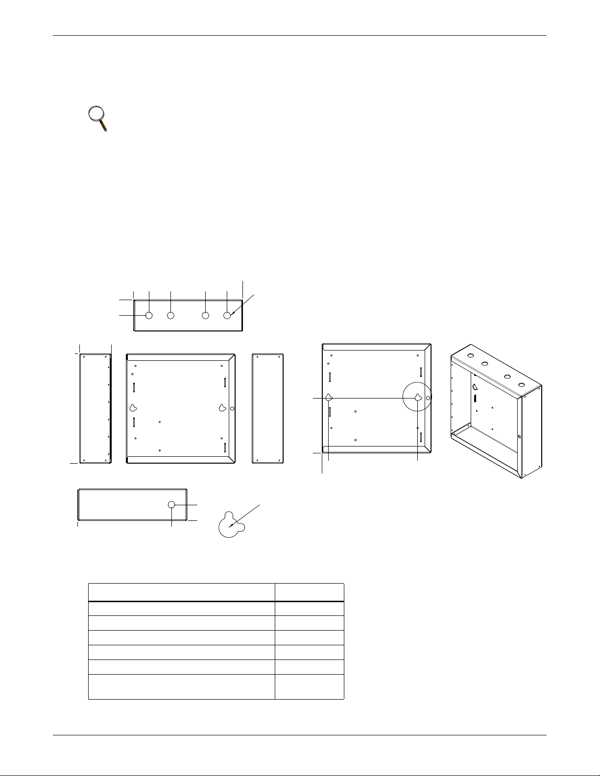
Placement and Cable Entry
The Liebert Battery Interface Board Box should be installed near the DC disconnect. The location should
allow access to the box and allow the front door to be opened for service. Access to the Battery Interface
Boards (BIB), fuse disconnects and terminal blocks are behind the front door. See Figure 1 for cable entry
layout.
1
Page 2
Control Connection
NOTE:
1. All dimensions are in inches (mm).
2. Mounting hardware must support the full
weight of units and be appropriate for the
material the box will be attached to.
Dia. 0.78 (20)
Knockout
4 Places
Mounting Slot Dia.
0.25 (6.4); 2 Each
Hole Cutout Dia.
0.63 (16); 2 Each
A
FRONT
BOTTOM
TOP
LEFT SIDE
0
4.3
(109)
8.3
(211)
10.8
(274)
12.6 (320)
0
12.6
(320)
0
1.8 (46)
1.8
(46)
1.8 (46)
0 10.8 (274)
0
RIGHT SIDE
0
3.6 (92)
FRONT (MOUNTING)
DETAIL A
0
0.7 (18)
11 (279)
0
6.3
(160)
536210GX - Submittal
Each Liebert NX Battery Interface Board Box contains two Battery Interface Boards (BIB). All DC systems
must have their Battery Interface Board controls connected in series. The control cables must be doubleinsulated. The wire must be 600V, 16-18 AWG stranded wire.
NOTE
Care must be taken to route control cables away from high-voltage cables and busbars. Use
recommended knockouts for installing all cables and use provided tie point to secure (see
Figure 2).
NOTICE
Risk of improper installation. Can cause equipment damage.
During system commissioning, Emerson Network Power Liebert Services will set the jumpers
on the External Interface Board in the Liebert NX UPS and the BIB. If another DC source is
added to the system after commissioning, it is imperative that Liebert Services reset the
jumpers on the EIB board and the BIB board.
Figure 1 Dimensions and layout
Table 1 Battery Interface Board Box specifications
Parameter
DC Sense Volts, VDC 384-576
DC Sense Current, IDC 0.5A
Shunt Trip Volts, VDC 220V
Dry Contacts Volts, VDC (Auxiliary Contacts) 220V
Dry Contacts Volts, VDC (Breaker Aux) 10mA
Mounting Hardware (supplied by others)
Value s
Must support
30 lb. (13.6kg)
2
Page 3

Figure 2 Layout and cable routing
Knockout for
CB wires
CB wires
Knockout for
UPS wires
TOP VIEW
UPS wires
FRONT VIEW
Knockout for
DC sense wires
BOTTOM VIEW
3
DC
sense
wires
Page 4

Figure 3 Wiring diagram
DC Positive (+)
DC Negative (-)
TB2
1
2
CIRCUIT
+220V(COIL)
-220V(COIL)
CLOSED
BREAKER
FEEDBACK
UPS
MONITOR
BOARD (U2)*
ONLINE
TEMPERATURE
* Refer to UPS
Installation Manual
DC Sense Connections
5A,700VDC
TB1
1
2
COM
OPEN
DRV
GND
GND
+12V
3
4
5
6
7
8
9
10
11
12
W/R
W/BLK
WHITE
WHITE
BLK
BRN
GRN
WHT
BLK
WHITE
RED
RED
BLACK
RED
UH8351A8
+220V-
J3
DRV
AUX
GND1
USE
J2
J4
BLK
W0
RED
BLK
UHW241C2
+220V-
X100
X102
X104
X103
X101
X107
1 2 3
X108
3 2 1
X106
X105
BLK
WHITE
RED
Connecting the optional DC sense voltage wires will allow the Liebert NX to display the DC source on the
UPS HMI. This connection cannot be used with split-battery bus systems, flywheel systems or any DC system
that does not have a valid DC voltage when the DC breaker is open.
If the DC sense wires are connected to the BIB, the DC source cabinet may require field-installed fuse
protection; refer to national and local codes to verify. The DC sense wires must run from the most-positive DC
voltage to the most-negative DC voltage
DC Breaker Shunt Trip Contacts
If the DC breaker is being used as a Module Battery Disconnect breaker (UPS will have control of the
breaker), then the 220V shunt trip contacts must be run to the BIB.
If the DC breaker is being used as a Battery Isolation Switch, then the 220V shunt trip contacts will not be
run to the BIB.
Liebert Corporation
1050 Dearborn Drive
P.O. Box 29186
Columbus, OH 43229
Telephone: 1-800-877-9222
Facsimile: 1-614-841-6022
www.liebert.com
© 2010 Liebert Corporation
All rights reserved throughout the world. Specifications subject
to change without notice.
® Liebert is a registered trademark of Liebert Corporation. All
names referred to are trademarks or registered trademarks of
their respective owners.
SL-25417_REV0_05-10
4
 Loading...