

Emerson KTM 2-WAY, KTM 3-WAY, KTM V-PORT Installation, Operation And Maintenance Instructions
Page 1

KTM 2-WAY, 3-WAY AND V-PORT BALL VALVES
INSTALLATION, OPERATION AND MAINTENANCE INSTRUCTIONS
Before installation these instructions must be read fully and understood
FIGURE 1 Selection
Bolting procedure
Ensure the valve’s materials of construction
and pressure/temperature limits shown on the
identification plate are suitable for the process
fluid and conditions. If in doubt contact the
manufacturer.
Transportation
• When lifting the ball valve by crane or hoist,
avoid hooking to inadequate areas of the
valve. Inadequate hoisting could cause
deformation of the valve or falling of the valve.
• Do not carry the valve by its handlever, or the
valve could drop down which will damage the
valve or injure the person.
These instructions summarize the main
warnings concerning the routine operations
asper the related installation and maintenance
manual.
Storage
When valves are to be stored for some time
before being fitted, storage should be in the
original delivery crates with any waterproof
lining and/or desiccant remaining in place.
Storage should be off the ground in a clean,
dry, indoor area. If storage is for a period
exceeding six months the desiccant bags
(ifsupplied) should be changed at this interval.
The ball valves are delivered with the ball in
full open position and should be stored as they
are. Keeping the ball in other position or half
opened position for an extended period of time
could cause seat leakage.
Protection
Valves are delivered with protection according
to customer’s specification, or in accordance
with the quality assurance manual, to protect
the valve seats and closure member from
damage. Wrapping and/or covers should be left
in place until immediately before fitting to the
pipe.
INSTALLATION
Refer to Figure 1
1. Valves are bi-directional as standard, unless
otherwise stated, and may be fitted in either
direction.
2. Installation may be carried out with stem
displaced through any angle permitted by
the bolting.
3. Remove protective covers from valve faces.
4. Ensure that mating flanges and gaskets are
clean and undamaged.
5. Should there be any possibility of abrasive
particles (weld slag, sand etc.) within the
piping system, this could damage valve
seating areas. The system will need to be
flushed clean.
6. Ensure mating pipe flanges are aligned
correctly, bolting should be easily inserted
through mating flange holes.
7. Fit the valve into pipework ensuring easy
access of the lever/handwheel.
8. Tighten the flange bolts in a diagonal
pattern. Uneven tightening could cause
leakage or gasket damage.
9. When sealing tape or sealing gel type
material is used, ensure that no torn off
piece or solidified fragment get into the
pipe system.
VCOSI-01861-EN 17/09© 2017 Emerson. All Rights Reserved.Emerson.com/FinalControl
Page 2
KTM 2-WAY, 3-WAY AND V-PORT BALL VALVES
INSTALLATION, OPERATION AND MAINTENANCE INSTRUCTIONS
PRESSURE TEST
• In case of pressure test of the pipe system,
the valve should be in a half-open position
and check the leakage from joint connection
or gland. If the test is performed with the
valve in close position, overload pressure on
the seat could cause seat leakage.
• The ball valve should be operated to either
full open or closed position. Prolonged use
in a half-open position could cause seat
deformation or seat leakage.
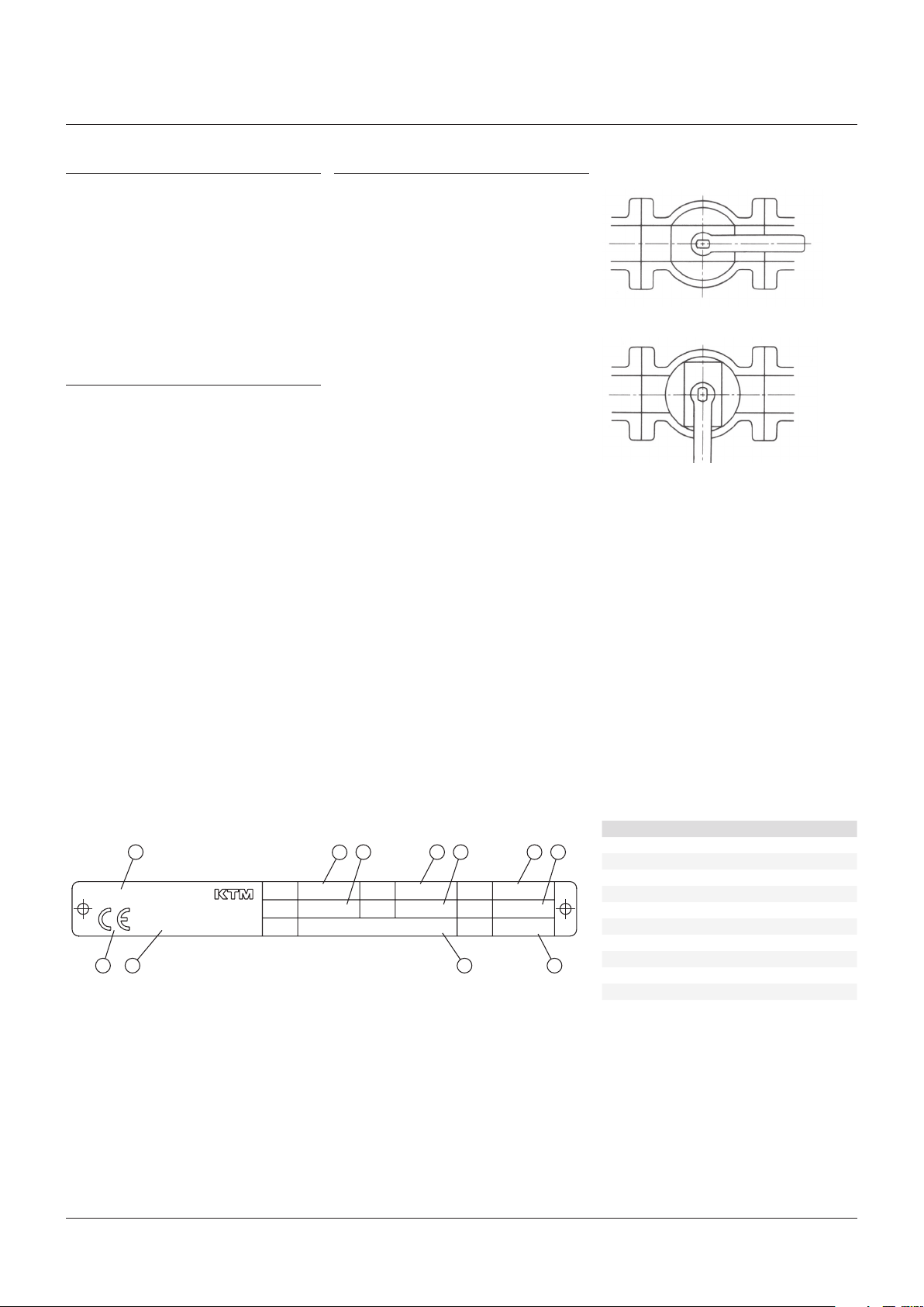
OPERATION
Refer to Figure 2
• The closed position of KTM ball valves is
indicated by either the handlever or the
direction of the parallel flats on the top of
the stem (see picture).
• All standard manually operated valves are
‘clockwise to close’.
• The valve requires no ‘additional tightening’
to shut off, excessive handle operation could
break the lever, injure the operator, or deform
the stopper or stem which may lead to seat
leakage.
MAINTENANCE
Refer to Figure 3
No routine maintenance is required other
than periodic inspection to ensure satisfactory
operation and sealing. Any sign of leakage
from the gland packing should be addressed
immediately by depressurizing the valve and
tightening the gland screws gradually and
evenly. If no further adjustment is possible,
or if seat or joint leakage is suspected, the
valve will require a complete overhaul. This
should be carried out after depressurization
and in accordance with specific maintenance
Instructions. Only original spares should be
used.
FIGURE 2
Open position
Closed position
FIGURE 3
Tagplate
7
4 5 8 63
SAITAMA
0062
1 2
Neither Emerson, Emerson Automation Solutions, nor any of their affiliated entities assumes responsibility for the selection, use or maintenance of any product.
Responsibility for proper selection, use, and maintenance of any product remains solely with the purchaser and end user.
KTM is a mark owned by one of the companies in the Emerson Automation Solutions business unit of Emerson Electric Co. Emerson Automation Solutions, Emerson and
the Emerson logo are trademarks and service marks of Emerson Electric Co. All other marks are the property of their respective owners.
The contents of this publication are presented for informational purposes only, and while every effort has been made to ensure their accuracy, they are not to be
construed as warranties or guarantees, express or implied, regarding the products or services described herein or their use or applicability. All sales are governed by
our terms and conditions, which are available upon request. We reserve the right to modify or improve the designs or specifications of such products at any time without
notice.
Emerson.com/FinalControl
JAPAN
ASME B16.34
CLASS
SEAT
RATING
TYPE
BODY
300 316
STEM
/CWP
CF8MEB12
SEAT
DATE
5150720
@
flF
10 11
BALL
CF8M
E
2001.12
9
PARTS LIST
Item Description
1 CE marking
2 Number of notified body
3 Identification and manufacturer
4 Valve type
5 Body material
6 Ball material
7 ASME class
8 Stem material
9 Seat material
10 P/T rating (max/min) of seat
11 Year and date of manufacture
2
 Loading...