

Page 1
Reference Manual
00809-0100-3003, Rev AD
GDU-Incus Ultrasonic Gas Leak Detector
December 2020
Page 2

Important instructions
Emerson designs, manufactures, and tests products to function within specific conditions. Because these products are
sophisticated technical instruments, it is important that the owner and operation personnel strictly adhere both to the
information printed on the product nameplate and to all instructions provided in this manual prior to installation, operation, and
maintenance.
WARNING
Installing, operating, or maintaining an Emerson product improperly could lead to serious injury or death from explosion or
exposure to dangerous substances.
Comply with all information on the product, in this manual, and in any local and national codes that apply to the product.
Do not allow untrained personnel to work with this product.
Use Emerson parts and work procedures specified in this manual.
In-depth specialist knowledge is required to work with and on the GDU-Incus.
Authorized personnel for installing, operating, servicing, and maintaining the GDU-Incus are instructed and trained qualified
personnel of the operating company and the manufacturer.
It is the operating company's responsibility to:
• Train staff
• Observe safety regulations
• Follow the Reference Manual
Operators must:
• Have been trained
• Have read and understood all relevant sections of the Reference Manual before commencing work
• Know the safety mechanisms and regulations
To avoid personal injury and loss of property, do not install, operate, maintain, or service this instrument before reading and
understanding this reference manual and receiving appropriate training.
WARNING
Heavy instrument
The GDU-Incus weighs 49 lb. (22 kg).
Take care when lifting and carrying the unit.
Ensure that all bolts and fixings selected for mounting are suitable for the weight and that the wall, pole, or mounting surface
is solid and stable.
WARNING
Physical access
Unauthorized personnel may potentially cause significant damage to and/or misconfiguration of end users’ equipment. This could
be intentional or unintentional and needs to be protected against.
Physical security is an important part of any security program and fundamental to protecting your system. Restrict physical access
by unauthorized personnel to protect end users’ assets. This is true for all systems used within the facility.
2
Page 3

NOTICE
The contents of this publication are presented for informational purposes only and while every effort has been made to ensure
their accuracy, they are not to be construed as warranties or guarantees, expressed or implied, regarding the products or services
described herein or their use or applicability. All sales are governed by Emerson's terms and conditions, which are available upon
request. We reserve the right to modify or improve the designs or specifications of such products at any time.
Emerson does not assume responsibility for the selection, use, or maintenance of any product. Responsibility for proper selection,
use, and maintenance of any Emerson product(s) remains solely with the purchaser and end user.
To the best of Emerson's knowledge, the information herein is complete and accurate. Emerson makes no warranties, expressed
or implied, including implied warranties of merchantability and fitness for a particular purpose with respect to this manual and, in
no event, shall Emerson be liable for any incidental, punitive, special, or consequential damages including, but not limited to, loss
of production, loss of profits, loss or revenue, or use and costs incurred including without limitation for capital, fuel and power,
and claims of third parties.
Product names used herein are for manufacturer or supplier identification only and may be trademarks or registered trademarks
of these companies.
The Emerson logo is a trademark and service mark of the Emerson Electric Company.
Copyright © 2020 by Emerson, Shakopee, Minnesota, United States
All rights reserved. No part of this work may be reproduced or copied in any form or by any means graphic, electronic, or
mechanical without first receiving written permission of Emerson, Shakopee, Minnesota, United States.
3
Page 4

4
Page 5

Reference Manual Contents
00809-0100-3003 December 2020
Contents
Chapter 1 Introduction.............................................................................................................. 7
1.1 Product overview.........................................................................................................................7
1.2 Service support............................................................................................................................7
1.3 Product recycling/disposal...........................................................................................................8
Chapter 2 Installation.................................................................................................................9
2.1 Safety messages.......................................................................................................................... 9
2.2 Unpack and inspect..................................................................................................................... 9
2.3 Dimensions................................................................................................................................10
2.4 Installation procedure................................................................................................................11
2.5 Mounting...................................................................................................................................13
2.6 Terminal compartment wiring...................................................................................................18
2.7 External cables...........................................................................................................................25
2.8 External ground......................................................................................................................... 26
2.9 Commissioning..........................................................................................................................27
Chapter 3 Operate....................................................................................................................29
3.1 Normal operation...................................................................................................................... 29
3.2 Check sensor functionality.........................................................................................................34
3.3 Output options..........................................................................................................................34
3.4 Display.......................................................................................................................................35
3.5 4-20 mA output......................................................................................................................... 36
3.6 Fault outputs............................................................................................................................. 37
Chapter 4 HART® functionality.................................................................................................39
Chapter 5 Maintenance............................................................................................................41
5.1 Hand-held test...........................................................................................................................41
5.2 Troubleshooting........................................................................................................................41
5.3 Storage......................................................................................................................................41
5.4 Spare parts and accessories....................................................................................................... 41
Chapter 6 Certifications........................................................................................................... 43
6.1 Marking..................................................................................................................................... 43
6.2 ATEX..........................................................................................................................................44
6.3 IECEx..........................................................................................................................................44
6.4 FM (US & Canada)...................................................................................................................... 44
6.5 INMETRO................................................................................................................................... 45
6.6 EAC............................................................................................................................................45
6.7 KTL............................................................................................................................................ 45
6.8 DNV...........................................................................................................................................45
Reference Manual 5
Page 6

Contents Reference Manual
December 2020 00809-0100-3003
6.9 ABS............................................................................................................................................45
6.10 Declaration of Conformity....................................................................................................... 46
6.11 China RoHS tables....................................................................................................................48
Appendix A Theory of operation................................................................................................. 49
6 GDU-Incus
Page 7

Reference Manual Introduction
00809-0100-3003 December 2020
1 Introduction
1.1 Product overview
The GDU-Incus is an ultrasonic gas leak detector used for detecting airborne ultrasound
generated from pressurized gas leaks. Airborne ultrasound is generated when gas moves
from a high pressure area to a low pressure area with a ratio in excess of 1.8 to 1 upstream
to downstream. However, Emerson only recommends this detector for pressures above 2
bar (30 psi) gauge. The intensity of airborne ultrasound generated is dependent on a
number of factors including gas pressure, gas leak size, and gas temperature.
The detector uses four individual Piezo ceramic sensing heads designed using a patentpending floating crystal design. The sensor design makes the sensing heads virtually
indestructible and totally immune to temperature, moisture, and other contaminants
found in hazardous areas. The detector uses a continuous electronic monitoring test
feature to ensure complete functionality.
The detector has a large dynamic range, which allows use in a wide range of applications,
from offshore platforms to gas transportation systems. The multi-stage amplifier ensures
a linear output across the entire detector range without drop-off at each end of the range.
The detector is not designed to detect specific gas types, LEL, or ppm. It responds
instantaneously to the ultrasound produced by a wide range of gas leak sizes and remains
unaffected by even the most extreme weather conditions. The detector is rated to IP66/
IP67 and NEMA® Type 4X to withstand harsh environments.
The detector is supplied with a 4-20 mA analog output and a HART® interface.
1.2 Service support
To expedite the return process outside of North America, contact your Emerson
representative.
Within the United States, call the Emerson Response Center toll-free number
1-800-654-7768. This center is available 24 hours a day to assist with any needed
information or materials.
The Response Center will ask for product model and serial numbers and will provide a
Return Material Authorization (RMA) number.
The Response Center will also ask for the installation and application details.
WARNING
Hazardous substances
Individuals who handle products exposed to a hazardous substance can avoid injury if they
are informed of and understand the hazard. If the product being returned was exposed to
a hazardous substance as defined by the Occupational Safety and Health Administration
(OSHA), a copy of the required Material Safety Data Sheet (MSDS) for each hazardous
substance identified must be included with the returned goods.
Reference Manual 7
Page 8

Introduction Reference Manual
December 2020 00809-0100-3003
1.3 Product recycling/disposal
Consider recycling equipment and packaging. Dispose of the product and packaging in
accordance with local and national legislations and regulations.
8 GDU-Incus
Page 9

Reference Manual
00809-0100-3003 December 2020
Installation
2 Installation
2.1 Safety messages
Instructions in this section may require special precautions to ensure the safety of
personnel performing the operations.
WARNING
Failure to follow these installation guidelines could result in death or serious injury.
Ensure that only qualified personnel perform the installation.
The area in which the detector is mounted must be in accordance with the certification
of the apparatus and in accordance with local or national standards.
Do not modify the enclosure or component parts; this will compromise the Hazardous
Area Certification.
Ensure that all wiring and power supply to the detector is within specified operating
parameters.
Except for the terminal cover, the GDU-Incus is a sealed unit. The main enclosure may
be opened only by Emerson or Emerson-authorized personnel. All warranties and
certifications are nullified if the seals are tampered with or broken.
The GDU-Incus is supplied without cable glands. Ensure that all cable entry threads are
sealed with an appropriate plug to eliminate water ingress and thread damage. At
installation, remove all shipping cable entry plugs and replace them with approved Ex d
cable glands or blanking plugs to meet hazardous locations requirements. If the
detector is to be installed in a Zone 1 Hazardous Area, an Ex d barrier seal must be used.
WARNING
Electrical shock could cause death or serious injury.
Use extreme caution when making contact with leads and terminals.
CAUTION
Equipment damage
Identification tags must be firmly secured to the GDU-Incus bracket to prevent unwanted,
locally-generated, ultrasonic noise. Refer to Figure 2-1.
2.2 Unpack and inspect
Procedure
1. Carefully remove all components from the packaging.
2. Verify the components against the enclosed packing list.
Reference Manual 9
Page 10
Installation
December 2020 00809-0100-3003
3. Inspect all components for obvious damage, such as broken or loose parts.
4. If any components are missing or damaged, contact your local Emerson
representative or the factory immediately.
Reference Manual
2.3 Dimensions
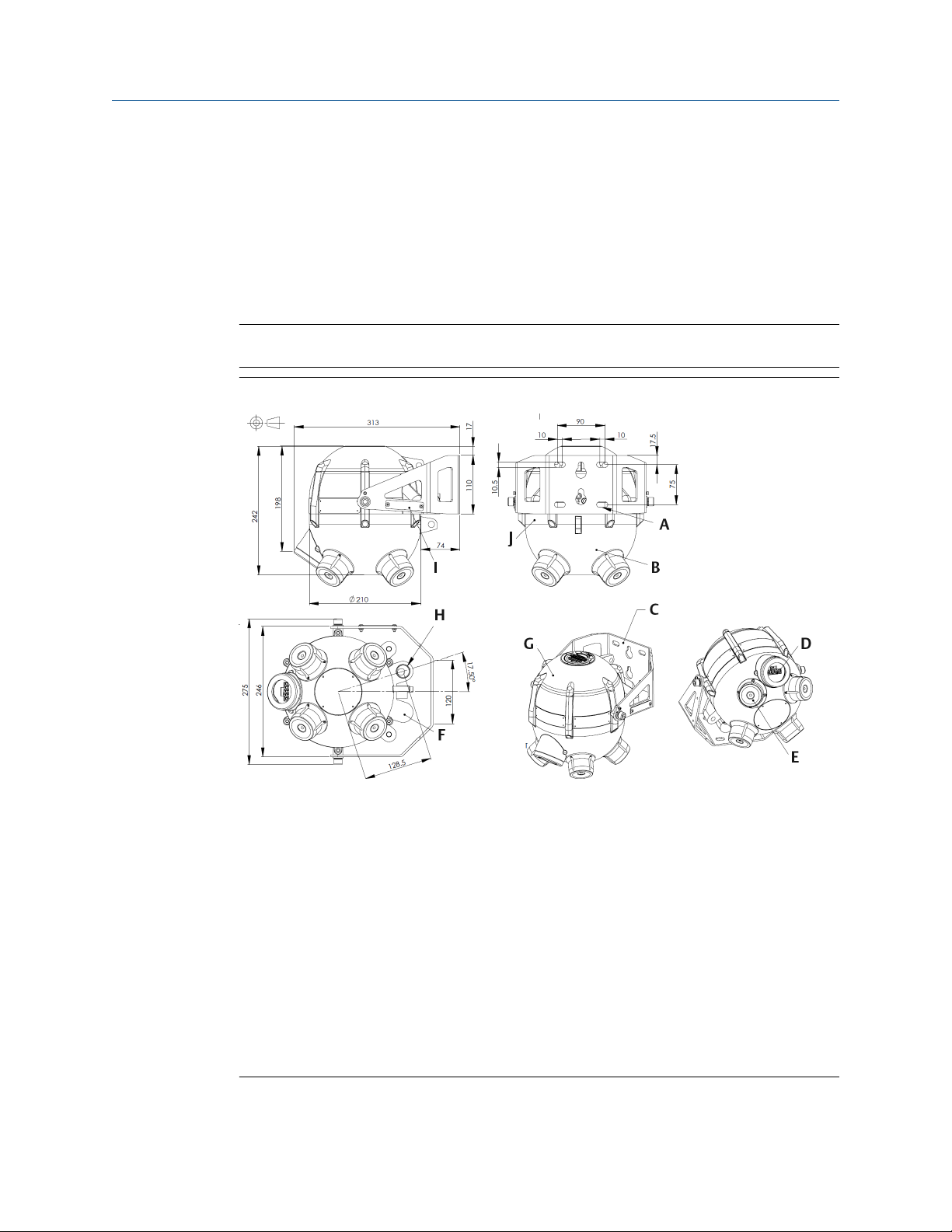
Refer to Figure 2-1 for the dimensions of the GDU-Incus.
Note
All dimensions are provided in millimeters.
Figure 2-1: Dimensions
A. Suitable for M10 or equivalent
B. Main body enclosure (housing)
C. Standard mounting bracket shown. U-bolt kits (for pole mounting) and a "DNV" certified
bracket are available.
D. Display
E. Sensor head (four positions)
F. Customer cable entry position available for dual entry/relay output (ATEX/IECEx units
only)
G. Terminal compartment housing
H. Customer cable entry M20 standard. M25 ½-in. national pipe thread (NPT) or ¾-in. NPT
alternative
I. Identification tag (sold separately) can be mounted on either side of bracket using holes
provided.
J. Top body enclosure (housing)
10 GDU-Incus
Page 11

Reference Manual Installation
00809-0100-3003 December 2020
2.4 Installation procedure
Emerson recommends mounting the GDU-Incus between 10 and 16 ft. (3 and 5 m) above
the floor level to eliminate ground reflections and absorption. You may mount the
detector lower than 10 ft. (3 m), but that may reduce the coverage; contact an Emerson
representative for more details.
Check the area of installation for equipment capable of generating high levels of spurious
airborne noise that would not be classified as "normal background noise", such as pressure
release valves, etc. If any are present in the detector range of coverage, contact Emerson
or monitor the detector when activated to ensure immunity.
2.4.1 Mechanical installation
The detector incorporates a dedicated flameproof terminal compartment certified to Ex d
and a flameproof main electronics compartment certified to Ex d, both sealed to IP66/
IP67.
CAUTION
Take care when removing the terminal cover during installation to ensure that the
flamepath surfaces are not scratched or damaged. See Wire the detector for more
information.
The detector has a large detection radius capability; take care when positioning it to use
the maximum coverage while eliminating blind spots and spurious alarms.
The detector has a variety of mounting options to incorporate installation into most
situations in industrial environments, such as wall/flat surface mounting (Mount to wall or
flat surface), vertical pole mounting (Mount to a pole), and mounting in an environment
where DNV certification is required (Mount DNV certified detector).
The detector should be mounted so that the four sensor heads are pointing vertically
downwards towards the floor or ground. See Figure 2-2.
Reference Manual 11
Page 12
Installation Reference Manual
December 2020 00809-0100-3003
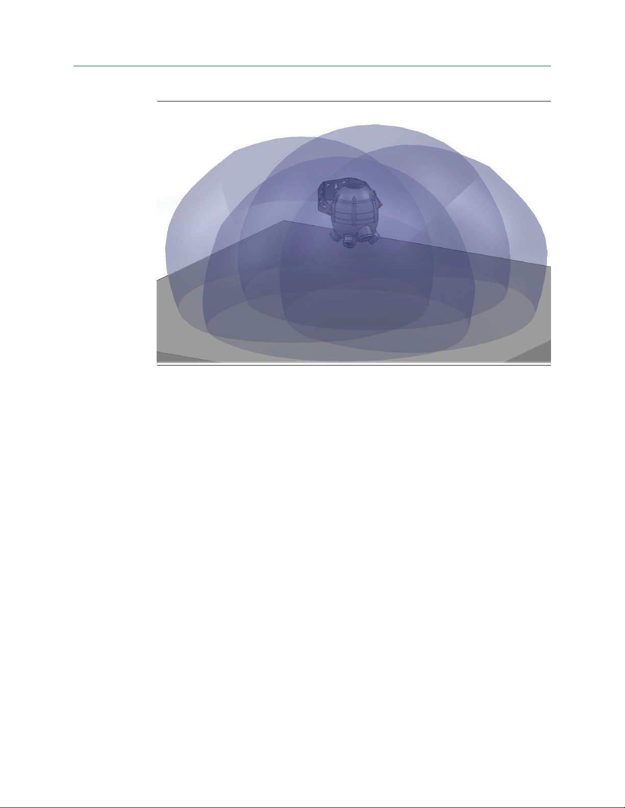
Figure 2-2: Three-Dimensional View of Detector Coverage.
The detector uses four independent sensor heads for full coverage. Figure 2-2 shows a
three-dimensional view of the coverage (detector not to scale) at a 10 ft. (3 m) height
above floor level with the detector pointing vertically downwards. The detector coverage
is specified as meters radius at the floor level, as this is the minimum sensing distance. As
shown, the entire area below the detector is covered, as well as some of the area above
and around the detector. Each sensor overlaps the next, so multiple sensors cover areas
underneath the detector.
12 GDU-Incus
Page 13
Reference Manual Installation
00809-0100-3003 December 2020
2.5 Mounting
2.5.1 Mount to wall or flat surface
When mounting on a vertical flat surface, such as a wall with no significant vibration, use
the standard mounting bracket supplied with the detector. If you suspect vibration at the
fixing point, contact an Emerson representative for additional options.
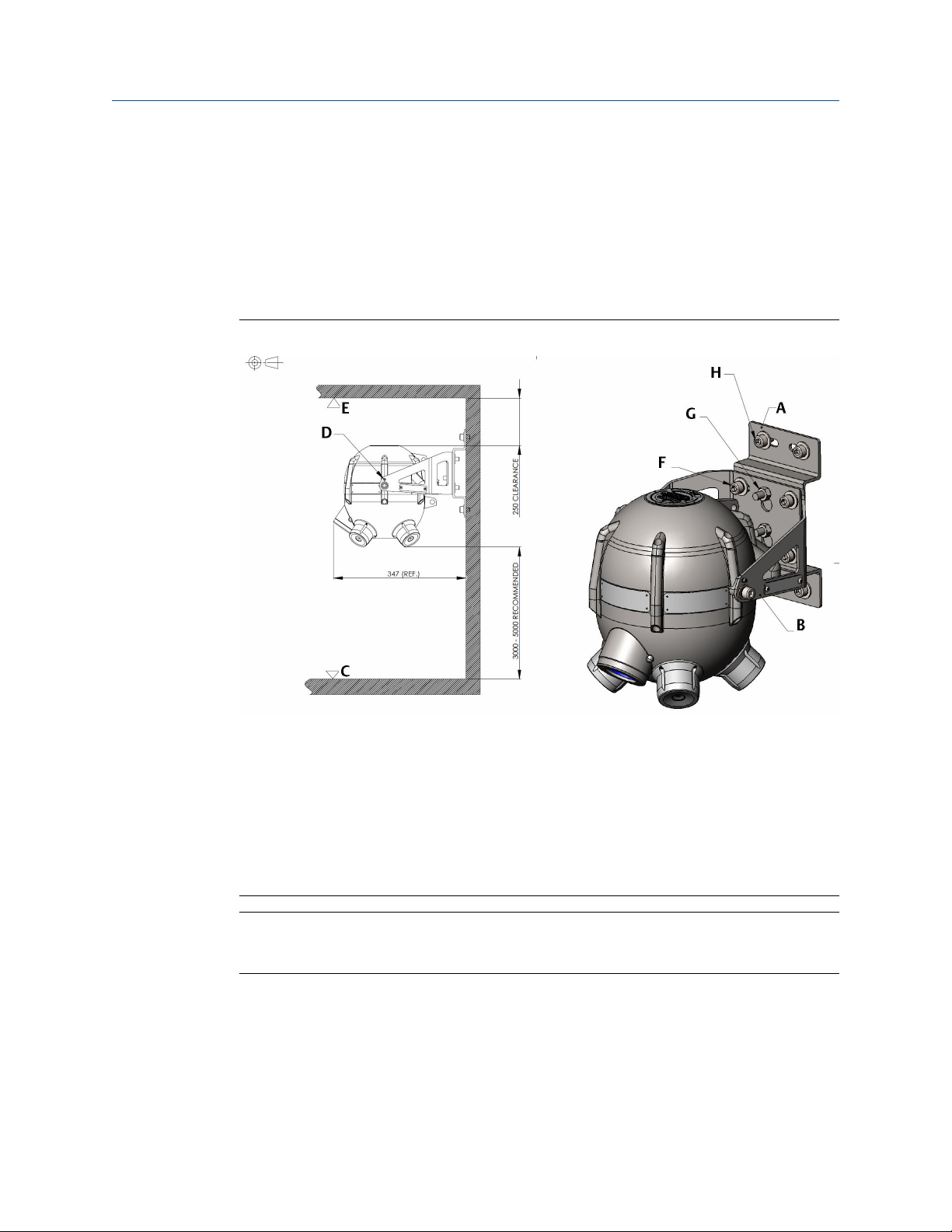
Figure 2-3: Wall/Flat Surface Mounting Diagram
A. Wall mounting bracket
B. Standard bracket
C. Floor
D. Vertical mounting locking fastener, typical both sides
E. Roof
F. See Step 3.
G. See Step 2.
H. See Step 1.
Note
GDU-Incus assembly weight: 39.7 lb. (18 kg). Ensure fixings are capable of supporting
assembly weight and local standards for shock loading.
Reference Manual 13
Page 14
Installation Reference Manual
December 2020 00809-0100-3003
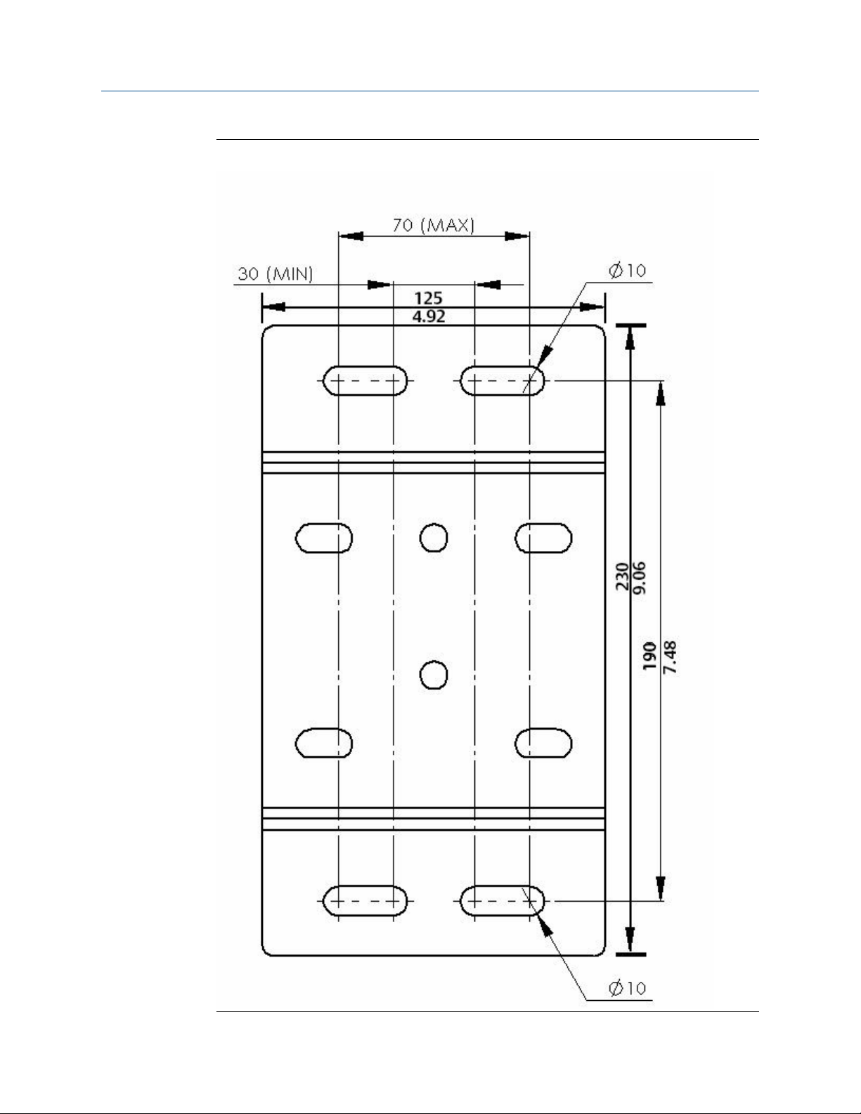
Figure 2-4: Wall Mounting Drilling Template
14 GDU-Incus
Page 15

Reference Manual Installation
00809-0100-3003 December 2020
Figure 2-4 shows the position of the mounting slots on the wall mounting bracket supplied
with the standard GDU-Incus. Drill pairs of Ø 0.4-in. (10 mm) holes on the mounting
surface between 1.2 in. (30 mm) and 2.8 in. (70 mm) apart, with a vertical distance of 3.5
in. (90 mm) between the two pairs of holes.
Procedure
1. Attach wall mounting bracket to wall of flat horizontal support using four M10
bolts.
2. Position the detector so that the standard bracket is on the studs of the wall
bracket. Secure the brackets together using the two M10 nuts supplied.
3. Permanently fix the brackets together using the socket head bolts and nuts
supplied.
Make sure to use spring washers.
2.5.2
Mount to a pole
In large open areas, Emerson recommends mounting the detector on a pole to take
advantage of the large omni-directional detection coverage.
Mount the detector 10 to 16 ft. (3 to 5 m) high to eliminate reflections and ground
absorption. You may mount the detector lower than 10 ft. (3 m), but coverage may be
reduced; contact an Emerson representative for details.
Make sure the pole complies with local standards and is capable of supporting the
detector weight at the installation height, taking environmental factors into
consideration.
Attach the detector to the pole using two U-bolts fixed to the pole mounting adapter (you
can use the wall bracket for pole mounting if the pole is 1.5 to 2 in. (38.1 to 50.8 mm)
diameter. Emerson suggests torquing to 45 Nm, but use local standards in the first
instance.
Reference Manual 15
Page 16
Installation
Reference Manual
December 2020 00809-0100-3003
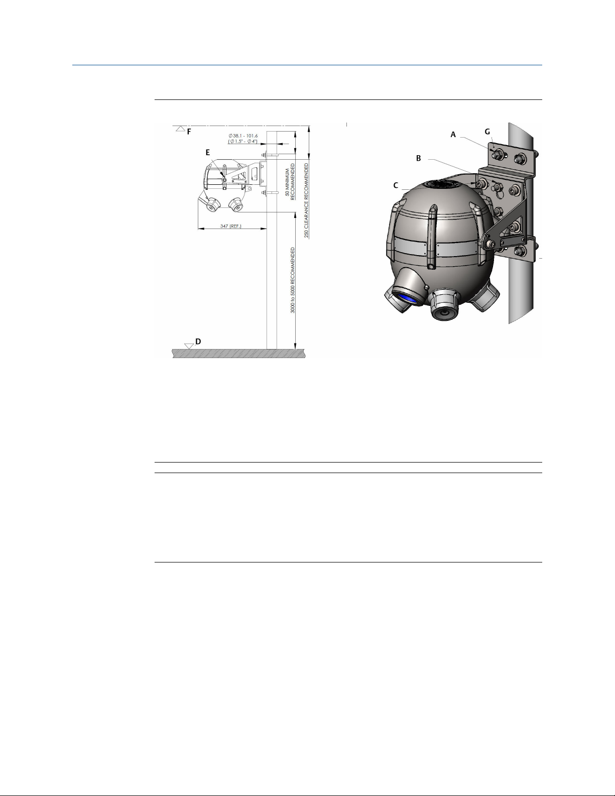
Figure 2-5: Pole Mounting Diagram
A. See
Step 1.
B. See Step 2.
C. See Step 3.
D. Floor
E. Vertical mounting locking fastener
F. Roof
G. Pole mounting adapter
Note
Specify U-bolt and pole mounting adapter size at time of order. Standard parts are
available for tube sizes from Ø 1.5 in. (38.1 mm) to 4 in. (101.6 mm).
Weight of detector is 39.7 lb. (18 kg) approximately. Specify free-standing pole size to
support the detector to local standards. Ensure calculations employ suitable civic factor of
safety to support extended weight at detection height. Ensure nyloc fixing nuts are
tightened to 45 Nm or to applicable local standards.
Procedure
1. Attach pole mounting adapter to pole using two M10 U-bolts. Secure using nyloc
nuts and/or spring washers.
2. Position the detector so that the standard bracket is on the studs of the pole
adapter. Secure the brackets together using the two M10 nuts provided.
3. Permanently fix the brackets together using the socket head bolts and nuts
supplied.
Use spring washers.
16 GDU-Incus
Page 17
Reference Manual Installation
00809-0100-3003 December 2020
2.5.3 Mount DNV certified detector
When an installation requires equipment to be DNV certified, you must mount the
detector using a DNV mounting bracket.
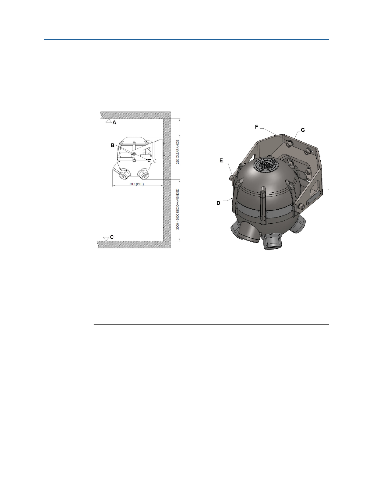
Figure 2-6: DNV Mounting Diagram
A. Roof
B. Detector permanently locked in vertical position by 4X M10 bolts (one either side and
two on underside of bracket)
C. Floor
D. See Step 3.
E. See Step 2.
F. See Step 1.
G. DNV mounting bracket: GDU-02-412
Figure 2-6 shows the mounting arrangement for DNV installation. Torque all bolts to
45 Nm and use spring washers in all cases.
Reference Manual 17
Page 18
Installation Reference Manual
December 2020 00809-0100-3003
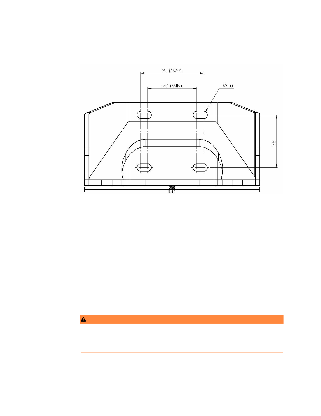
Figure 2-7: DNV Mounting Drilling Template
Figure 2-7 shows the position of the mounting slots on the DNV mounting bracket
supplied with the DNV detector. Drill pairs of Ø 0.4-in. (10 mm) holes between 2.8 in.
(70 mm) and 3.5 in. (90 mm) apart, with a vertical distance of 3 in. (75 mm) between the
two pairs of holes.
Procedure
1. Attach DNV mounting bracket directly to wall or flat horizontal support using 4 M10
bolts as shown.
Use spring washers.
2. Rest the detector on the flat base plate of the DNV bracket and secure using M10
bolts either side, making sure to use spring washers.
3. Secure the detector to the base plate using two M10 bolts, making sure to use
spring washers.
2.6 Terminal compartment wiring
WARNING
Failure to follow these installation guidelines could result in death or serious injury.
Ensure that only qualified personnel install the detector.
18 GDU-Incus
Page 19

Reference Manual Installation
00809-0100-3003 December 2020
WARNING
Electrical shock could cause death or serious injury.
Use extreme caution when making contact with the leads and terminals.
Do not open the detector's enclosure in a classified area or where an explosive
atmosphere may be present unless the power to the detector has been removed.
The detector's terminal cover is certified to flameproof standards; do not open it while
energized.
NOTICE
Connect the detector housing to local ground via the external earth point as shown in
Figure 2-12. Make sure the ground wire is a minimum of 4 mm2 (8 AWG) and as short as
possible. Make sure termination at the detector is suitable for M6 (0.25-in.) fastener.
Ensure earth wire is attached using the supplied spring washer.
The standard GDU-Incus is temperature rated between -40 and +185 °F (-40 and +85 °C),
and the heated variant is temperature rated between -67 and +185 °F (-55 and +85 °C).
Ensure that all cable is rated to the appropriate temperature of installation.
Reference Manual 19
Page 20

Installation
December 2020 00809-0100-3003
Reference Manual
2.6.1 Wire the detector
NOTICE
Wiring codes and regulations may vary. Wiring must comply with all applicable regulations
relating to the installation of electrical equipment in a hazardous area and is the installer's
responsibility. If in doubt, consult a qualified official before wiring the system.
In applications where wiring is installed in a conduit, do not use the conduit for wiring to
other equipment.
For full EMC requirements, ensure incoming cables are threaded through the ferrite beads
(provided with the detector). See Figure 2-8.
Figure 2-8: Ferrite Bead Locations
A. Thread cable through ferrite
B. Ferrite
20 GDU-Incus
Page 21

Reference Manual
Installation
00809-0100-3003 December 2020
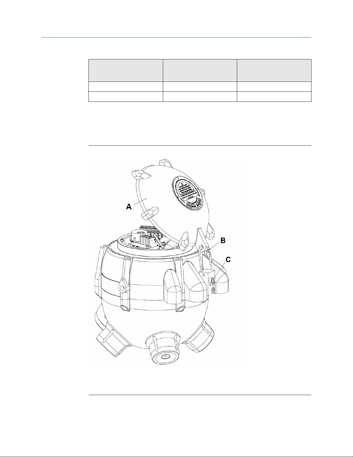
Procedure
1. To gain access to the terminal compartment, undo the six terminal cover fixing
screws and raise the terminal cover vertically until clear of the main enclosure.
The terminal cover is held in place with a stainless steel wire. You can lower the
terminal cover to the side of the detector during installation, but take care to
ensure the flame path is not damaged. Refer to Figure 2-9 for the flamepath details.
Figure 2-9: Flame Path Details
A. Terminal cover
B. Flame path
C. O-ring
2. Tighten the six terminal cover fixing screws to a torque of 9 Nm.
Reference Manual 21
Page 22

Installation Reference Manual
December 2020 00809-0100-3003
WARNING
Ensure cable entry is via suitable hazardous area approved and ingress
protection certified cable glands (customer supplied) or conduit.
The ATEX/IECEx approved GDU-Incus has two positions for M20 cable glands,
while the FM approved detector has one position for ¾-in. national pipe thread
(NPT) conduit.
Fit cable glands and conduit in accordance with manufacturers' instructions for
assembly to a certified flame-proof enclosure.
Seal all unused cable entries with a flame-proof certified plugging device.
Ensure all cable gland and plugging devices are ingress protected to the same
standard as the enclosure to maintain certification and are suitable for the size
of the cable used.
If the detector is to be installed in an ATEX Zone 1 Hazardous Area, use an Exd
barrier seal.
Seal all FM approved detectors (US and Canada) within 18 in. (457.2 mm) of
enclosure entry using a suitably rated conduit seal.
NOTICE
The terminal cover label specifies thread size for cable entry. See Marking for further
information.
3. Seal the terminal compartment with two O-rings to prevent water ingress.
Before closing, Emerson recommends visually inspecting the detector to ensure the
O-rings are in place and undamaged. Also check the flame paths of the terminal
cover and main enclosure for signs of damage. See Figure 2-9 for O-ring and flame
path positions.
4. Connect cable shield to instrument earth in the control room only unless extra radio
frequency interference (RFI) protection is required and all local and site grounding
regulations are met, in which case, terminate the shield to local ground via one of
the internal earth points shown in Figure 2-10.
22 GDU-Incus
Page 23

Reference Manual
Installation
00809-0100-3003 December 2020
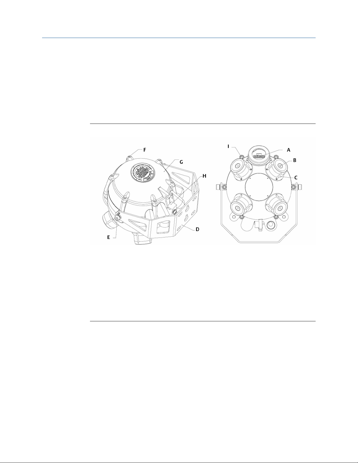
Figure 2-10: GDU-Incus Terminal Compartment Diagram
A. Customer cable entry position 1
B. M4 internal earth point for use with multiple cable entry
C. Ferrite supplied in box
D. Terminal row 1
E. Terminal board
F. Terminal row 2
G. M4 internal earth point for use with multiple cable entry
H. Customer cable entry position 2 (not available for FM certified detectors)
Figure 2-10 shows a view of the GDU-Incus with the terminal cover removed. For
single entry enclosures, enter customer cable via position 1; use positions 1 and 2
for dual entry enclosures.
The terminals are separated into power and communications for terminal row 1 and
relay outputs for terminal row 2.
Reference Manual 23
Page 24

Installation Reference Manual
December 2020 00809-0100-3003
2.6.2 Wiring configurations
Figure 2-11: Electrical Connection Drawing
A. Terminal row 1
B. Terminal row 2
Table 2-1: Terminal Row 1
Symbol Description
Single cable entry internal earth
0V 24 V return - (0 V)
+24v +24 Vdc (15 to 30 Vdc)
mA 4-20 mA output
24 GDU-Incus
Page 25

Reference Manual Installation
00809-0100-3003 December 2020
Table 2-2: Terminal Row 2
Abbreviation Description
F NO Fault relay normally open
F NC Fault relay normally closed
F C Fault relay circuit contact
A1 NO Alarm 1 normally open
A1 NC Alarm 1 normally closed
A1 C Alarm 1 circuit contact
485+ Factory use only
485- Factory use only
F1 Factory use only
F2 Factory use only
Refer to Table 2-1 and Table 2-2 for descriptions of the cable entries for terminal rows 1
and 2.
According to standard, connect three-wire connection cables to Terminal Row 1 in
positions +24v, 0V, and current loop output connected to the mA terminal. The maximum
loop resistance is 500 Ω.
Current source is the standard default operation; current sink is an option you should
specify when you order.
Relay data: 1.4 A, 30 Vdc switch voltage.
For a full description of relays, refer to Relay options.
2.7 External cables
WARNING
Choose customer cable in accordance with hazardous area certification and applicable
local regulations.
The GDU-Incus has a temperature rating of 185 °F (85 °C). When used in areas with an
ambient temperature above 140 °F (60 °C), ensure cable has a rating that is equal to or
exceeds the proposed maximum working temperature.
The following data indicates maximum cable length restriction due to voltage drop based
on a nominal input voltage of 24 Vdc.
Conductor cross sectional
area/gauge
Maximum cable length for
standard, non-heated GDUIncus
Maximum cable length for
heated GDU-Incus
0.5 mm2, 20 AWG 1770 ft. (540 m) 240 ft. (75 m)
1.0 mm2, 18 AWG 2800 ft. (855 m) 380 ft. (115 m)
Reference Manual 25
Page 26
Installation
Reference Manual
December 2020 00809-0100-3003
Conductor cross sectional
area/gauge
1.5 mm2, 16 AWG 4470 ft. (1360 m) 620 ft. (185 m)
2.5 mm2, 14 AWG 7120 ft. (2170 m) 990 ft. (300 m)
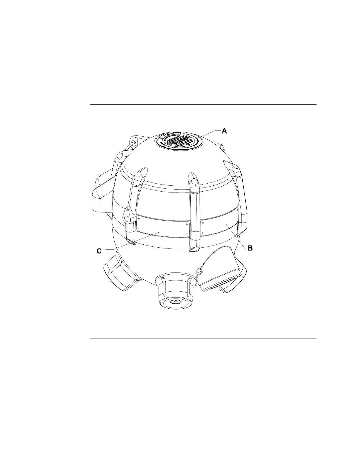
2.8 External ground
Connect the detector housing to local ground via the external earth point as shown in
Figure 2-12.
Figure 2-12: External Grounding Point
Maximum cable length for
standard, non-heated GDUIncus
Maximum cable length for
heated GDU-Incus
A. Terminal cover in open position
B. Terminal cover restraint
C. M6 external earth point
26 GDU-Incus
Page 27
Reference Manual
00809-0100-3003 December 2020
Installation
2.9 Commissioning
2.9.1 Visual inspection
Before powering the detector, inspect the following:
Refer to Figure 2-13 for key locations on the GDU-Incus when completing this inspection.
Figure 2-13: Components of the GDU-Incus
A. Display
B. Sensor (four positions)
C. Sensor pod (four positions)
D. Mounting bracket
E. Enclosure mounting point
F. Terminal cover bolts (six positions). Tighten to 9 Nm.
G. Terminal cover
H. External earth point
I. Main enclosure bolts (six positions). Do not remove or adjust.
• Ensure detector is correctly situated for area of detection.
• Ensure mounting bracket is secured to mounting points on the detector and mounting
surface/pole.
• Check pole mount (if present) for suitability to withstand detector weight and
measurement
• Ensure external earth is correctly attached using spring washer.
• Ensure correct cable gland installation and appropriate certification or local regulations
have been observed. Check correct cable installation in the terminal compartment;
ensure terminal compartment flame paths and seals are intact.
• Ensure incoming cable is threaded through ferrite beads (Figure 2-8).
Reference Manual 27
Page 28

Installation Reference Manual
December 2020 00809-0100-3003
• Tighten terminal cover bolts to the 9 Nm recommended torque.
• Verify main enclosure bolts are in place. Emerson torques these bolts at the factory; do
not adjust or tamper with them.
• Check display glass for damage or contaminants that may display.
• Ensure correct operating supply voltage.
2.9.2 Power up
Upon power up, a brief functionality check runs to ensure detector functionality; this lasts
no more than five seconds. Once completed, the detector goes into normal operation
using the factory/customer defaults specified at time of order or signals any faults that
may be present.
See Fault outputs for factory default options and for a list of faults.
In addition, the display shows the real-time ultrasonic sound level, the detector becomes
responsive to commands for function setup via hand-held TREX or AMS, and all relays are
energized or de-energized as per defaults.
Note
If Emerson has set the detector at the factory for specific site requirements, Emerson
recommends carrying out the steps in Check sensor functionality before you finish
commissioning.
28 GDU-Incus
Page 29

Reference Manual Operate
00809-0100-3003 December 2020
3 Operate
3.1 Normal operation
On power-up, the detector initializes a diagnostic check and then enters normal operation
mode as per factory default settings.
Factory operation mode 71 settings
• 4-20 mA = 4-120 dB (linear scale factor).
• Relays are energized open; loss of power causes alarm (fail-safe).
• Relays are set to non-latching.
• Reset alarms enabled; allows latched relays to be reset and restarts alarm delay.
• Alarm level set to 70 dB for relay output.
• Delay time set to 15 seconds for relay output.
3.1.1
• All communication ports are active and ready to receive commands.
Alarm level
The alarm level is the ultrasonic sound level at which an alarm state is triggered. During
the alarm state, the display flashes, the relays switch states, and the current loop becomes
active if one or more sensors were in fault mode (if no sensors are in fault, the current loop
will already be outputting dB level).
To avoid false alarms, Emerson recommends setting the alarm level above the background
level established by mapping when all processes are operational. If you don't know the
background level, Emerson recommends using the detector to analyze the background.
Take care to observe all processes that may cause intermittent ultrasonic noise, such as
pressure relief valves.
Contact an Emerson representative for advice on alarm levels.
Note
The higher the alarm level, the smaller the detector coverage radius; it is therefore
important to establish a safe alarm level at the lowest permissible rate.
Reference Manual 29
Page 30

Operate
Reference Manual
December 2020 00809-0100-3003
Figure 3-1: Suggested Alarm Levels
A. Alarm level (dB), 6 dB above background sound level
B. Background sound level (dB)
Figure 3-1 shows the suggested alarm level settings (6 dB above background sound level)
for known background sound levels. The values shown have been found to provide
sufficient immunity against most spurious alarms; however, take care to survey the area of
installation for potential spurious noise.
If you don't know background levels, use typical historical process background levels along
with a safety factor. Contact an Emerson representative for historical values and guidance.
You can set alarm levels in the detector (via HART®/TREX/AMS) or at the control panel.
Most installations set the alarm levels in the control system. However, please note that the
best practice is to have the control panel and the GDU-Incus's internal alarm level to
always mirror each other. The reason for this is when the detector is in a sensor fault
condition, the detector's mA output will be a constant 2 mA and will not change to the real
30 GDU-Incus
Page 31

Reference Manual
00809-0100-3003 December 2020
time mA output (which can be converted to real-time dB) until the device's internally set
alarm level is reached or exceeded.
For example, assume a sensor fault is present and the detector's internal alarm level is set
at 70 dB. The detector's mA output will be 2 mA until the real time dB level meets or
exceeds 70 dB, at which point the detector's mA output will change to the mA value that
coincides with the real-time 70 db level the detector is sensing.
Lastly, the display on the detector will read the real time dB values at all times, regardless
of the mA loop output.
Operate
3.1.2 Delay time
To avoid spurious alarms, Emerson recommends using a delay time for non-toxic gas
applications or when instantaneous detection is not required. The delay timer is activated
from the point at which the alarm threshold is first exceeded.
If ultrasonic noise drops below the alarm level threshold, the delay time is reset as shown
in Figure 3-3. If the ultrasonic noise level remains above the alarm level threshold for the
duration of the delay time, the alarm is activated as shown in Figure 3-2.
Figure 3-2: Graph Showing Alarm Activation with Leak
A. Ultrasonic sound level
B. Time duration (seconds)
C. Delay time (30 seconds)
D. Delay reached - alarm
E. Delay start point
F. Ultrasonic noise level
G. Background noise level
H. Alarm level
Reference Manual 31
Page 32

Operate Reference Manual
December 2020 00809-0100-3003
Figure 3-3: Graph Showing No Alarm Activation with Spurious Noise
A. Ulstrasonic sound level
B. Delay start point
C. Noise 1
D. Alarm dB exceeded
E. Delay reset
F. Delay start point
G. Delay reset
H. Noise 2
I. Delay time (30 seconds)
J. Noise 3
K. Delay start point
L. Delay reset
M. Alarm level
N. Background noise level
In Figure 3-3, noises 1 and 2 are spurious noise spikes of approximately 1.5 seconds,
typical of man-made ultrasonic noise produced through normal maintenance procedures.
Noise 3 is a longer spurious noise of approximately 13 seconds, typical of a pressure relief
valve. Delay time is introduced to ignore spurious noise spikes, as the detector will reset
when noise level drops below alarm level before the delay time is reached.
32 GDU-Incus
Page 33

Reference Manual
Operate
00809-0100-3003 December 2020
Figure 3-4: Graph Showing Alarm Activation with Spurious Noise and Leak
A. Ultrasonic sound level
B. Time duration (seconds)
C. Delay time (30 seconds)
D. Delay reached - alarm
E. Noise 1
F. Noise 2
G. Delay start point
H. Alarm level
I. Background noise level
Figure 3-4 shows detector response when a leak is encountered during a spurious noise
spike, such as a pressure relief valve. Noise 1 represents a pressure relief valve actuating
for approximately 13 seconds before a leak (noise 2) occurs. The detector starts the delay
time when the pressure relief valve opens and continues to monitor for leaks. If a leak
occurs during a spurious noise spike, the delay time is reduced by the duration of the
spurious noise spike.
It is important to identify all spurious noise spikes of significant duration within the
detector coverage. Emerson recommends setting the alarm delay to a value greater than
the maximum spurious noise spike operating duration. If two or more spurious noise
sources are situated within the detector coverage area, Emerson recommends assessing
whether activation of these sources can overlap in time, in which case you should extend
the delay time accordingly.
Reference Manual 33
Page 34

Operate
December 2020 00809-0100-3003
The factory alarm delay value is set at 15 seconds. To modify this value, connect to the
GDU-Incus with a hand-held TREX device or AMS. Please note when changing the alarm
delay that setting values 0 to 99 are in 10 second increments and 100 to 127 are in 1
second increments. 0 and 100 represent instantaneous alarms. For example, 1 represents
a 10 second alarm delay, and 99 represents a 990 second alarm delay; whereas 101
represents a 1 second alarm delay, and 127 represents a 27 second alarm delay. Therefore,
the factory alarm delay value for 15 seconds would be 115. See Table 3-1 for more
information.
Table 3-1: Alarm Delays
Desired alarm delay value Actual input value in TREX/AMS
15 seconds (factory default) 115
10 110
30 3
60 6
0 0 or 100
Reference Manual
3.1.3 Automatic self-test
The automatic self-test checks the complete detector every 320 milliseconds by sending
an electrical signal of known amplitude through the sensing circuitry and analyzing the
result, without interrupting the normal functionality of the sensor.
If drift, component failure, or damage occurs, the automatic self-test signals a fault. Refer
to Fault outputs.
3.2 Check sensor functionality
Emerson calibrates the sensors on the GDU-Incus at the factory; they do not need to be
adjusted. Before operation, Emerson recommends functionality checks to ensure correct
installation. On power-up, the detector performs a diagnostic check to ensure all main
functions are operational and continuously monitors the sensors via the built-in self-test.
The sensor's functionality can be verified using the GDU-01-TT Ultrasonic Test Transmitter
(see Spare parts and accessories for more information), using the following procedure:
1. Ensure that the background ultrasonic level is suitable for the distance of the
proposed transmitter test.
2. Aim the transmitter at the sensor face from a known distance. The detector's
display dB level will rise according to the hand-held device used and the distance.
3. Check all four sensors, if possible, by moving around the detector and repeating.
3.3 Output options
The GDU-Incus comes with the following industry-standard forms of communication:
• Analog (4-20 mA)
34 GDU-Incus
Page 35

Reference Manual Operate
00809-0100-3003 December 2020
• HART® communication protocol
This enables the detector to be operated as part of a system, as a standalone unit, or hard
wire linked to form a sub network.
3.3.1 Relay options
The GDU-Incus has two relays configured as follows for the standard factory default:
Table 3-2:
Relay Type Factory default setting
1 Fault Energized in normal operating condition, de-
energized in fault condition, non-latching
2 Alarm Energized in normal operating condition, de-
energized in fault condition, non-latching
Table 3-3: Relay Data
Maximum switching current 1.4 A
Maximum switching voltage 30 Vdc
You can change relay configuration to suit installation requirements with the user
changeable functions; options include normally open/normally closed condition and
latching/non-latching.
3.4 Display
The GDU-Incus incorporates a five-digit segment, 0.31-in. high x 0.16-in. wide (8 mm high
x 4 mm wide) character light-emitting diode (LED) display with red numerals as standard.
During operation, the real-time dB level is continuously shown while below the
programmed alarm level and flashing when above the programmed alarm level.
Figure 3-5: Example of Real-Time dB Level Display: 53db
Reference Manual 35
Page 36

Operate
December 2020 00809-0100-3003
Reference Manual
3.5 4-20 mA output
Figure 3-6: 4-20 mA Output Values (Example Shows Default Op-Mode 71)
Note
The GDU-Incus is providing coverage when the 2.0 mA sensor test fault is active; see 2.0
mA sensor test fault for more information.
Figure 3-6 shows the 4-20 mA output values for the detector during normal operation and
under various fault conditions. The value on the left side shows the mA output tolerance
band; internal fault is set for a 1.0 mA output with a tolerance of 0.8 to 1.2 mA, for
example.
36 GDU-Incus
Page 37

Reference Manual
00809-0100-3003 December 2020
All mA outputs are grouped in descending order to signify importance and to allow for
instant status recognition; see Fault outputs.
Normal operation between 4 to 20 mA (±0.2 mA): detector working, no fault conditions.
Operate
3.6 Fault outputs
3.6.1 2.0 mA sensor test fault
One or more sensor heads fail to respond with the correct value during the automatic selftest.
Output is continuous at 2.0 mA unless the test is subsequently passed successfully or an
alarm condition occurs, in which case the normal sound level is transmitted on the current
loop. See Alarm level for more information regarding alarm settings.
3.6.2
3.6.3
3.6.4
1.0 mA internal process fault
Continuous 1.0 mA (±0.2 mA) output for any known internal or external faults that include
over-voltage, high/low external voltage, blown fuse, or high/low internal voltage.
0.5 mA "All Sensors dead" fault
Continuous 0.5 mA (±0.2 mA) output, indicating that all four sensors have failed self-test.
Firmware version 3.4 onwards.
Recommended action
Contact your Emerson representative.
Zero mA major fault
Zero (0) mA output is either caused by a total loss of power to the detector or a serious
microprocessor fault.
Potential cause
Loss of power
Recommended action
The fault will be cleared when power is applied to the detector.
Potential cause
Serious microprocessor fault
Recommended action
Contact your Emerson representative.
Reference Manual 37
Page 38

Operate Reference Manual
December 2020 00809-0100-3003
38 GDU-Incus
Page 39

Reference Manual HART® functionality
00809-0100-3003 December 2020
4 HART® functionality
The GDU-Incus has HART communication enabled by default. The HART communication
mode is standard current output FSK, to HART protocol revision number 7.
The device reports the primary variable (PV) measurement of sound pressure level in units
of dB. The secondary variable (SV) reports the internal case temperature (degrees Celsius)
of the detector. The tertiary variable (TV) reports the temperature of the heated section of
the detector if the heater option is fitted; otherwise, it will report the same data as the
secondary variable.
A device description (DD) file for Emerson AMS and the hand-held TREX field terminals is
available from Emerson. In addition, you can use the detector with FDT frame applications
using a generic DTM.
The Incus HART Field Device Specification provides full technical details of the HART
interface.
Note
1. The detector does not support the delayed-response mechanism, burst-mode, or
write protection.
2. The HART device parameters Tag and Long Tag are set to INCUS and GDU-02-INCUS
by default. If unique identification is required, set up the parameters on site.
Reference Manual 39
Page 40

HART® functionality Reference Manual
December 2020 00809-0100-3003
40 GDU-Incus
Page 41

Reference Manual Maintenance
00809-0100-3003 December 2020
5 Maintenance
5.1 Hand-held test
You can use the GDU-01-TT test transmitter to emit an ultrasonic tone of 40 kHz with a
sound pressure level of approximately 106 dB at 3 ft. (1 m). Using the GDU-01-TT handheld device makes testing the GDU-Incus and other types of ultrasonic detectors quick and
cost-effective, as you can test at floor level at distances of up to 26 ft. (8 m) (dependent on
background noise) if you can achieve line of sight with the sensor.
Emerson recommends disabling all alarms and monitoring the 4-20 mA output from the
control room or observing it on the display. Test to ensure that the sensors are functioning
correctly in addition to any internal test function contained within the detector. Emerson
recommends doing a hand-held test in line with existing site maintenance procedures.
Note
Ensure that any internal test functions are disabled or deactivated when doing a handheld
test to avoid spurious results.
WARNING
This device will need a Hot Work Permit.
5.2 Troubleshooting
The GDU-Incus cannot be repaired in the field.
If a problem develops, carefully check installation and wiring. If you determine that the
problem is caused by an electronic or other defect, contact your Emerson representative.
Refer to Service support for instructions.
5.3 Storage
Store the detector in a location free from dust and moisture.
Make sure the storage temperature is well within the limits of the certified temperatures
of the equipment.
5.4 Spare parts and accessories
Part number Description
GDU-01-TT GDU test transmitter, battery-operated, and charger
GDU-01-TT-CHARGER 18 V 0.83 A standard charger for the GDU test transmitter
GDU-02-360-KIT GDU Incus 2-in. pipe U-bolt kit
GDU-02-370-KIT 4-in. pipe mount bracket kit. Material: stainless steel
Reference Manual 41
Page 42

Maintenance Reference Manual
December 2020 00809-0100-3003
Part number Description
GDU-02-TCFK Terminal fastener kit
GDU-02-TCL Terminal cover O-ring lower for Incus
GDU-02-TCU Terminal cover O-ring upper for Incus
GDU-INCUS-MTBR-S GDU Incus wrap-around mounting bracket, 316 stainless steel
GDU-INCUS-TCFK Terminal fastener kit: replacement terminal cover fasteners and
retaining washers
42 GDU-Incus
Page 43
Reference Manual Certifications
00809-0100-3003 December 2020
6 Certifications
6.1 Marking
Figure 6-1: Nameplate Locations
A. Terminal cover plate
B. Nameplate
C. Certification plate (ATEX/FM)
The GDU-Incus has several areas that contain important information for installation and
use. Figure 6-1 shows the positions of the nameplate, certification plate, and terminal
cover plate. The plates supply information to comply with ATEX Directive 2014/34/EU;
ensure that all three are fitted and clearly legible before installation.
Reference Manual 43
Page 44

Certifications
December 2020 00809-0100-3003
Reference Manual
6.2 ATEX
II2 G Ex db ib IIB+H2 T4 Gb IP66/IP67
T amb -XX °C to +85 °C
XX is -55 °C when fitted with heating device.
XX is -40 °C when no heating device is fitted.
Special Conditions for Safe Use (X):
1. As flameproof joint lengths exceed the relevant minimum dimensions given in IEC
60079-1:2014 Clauses 5.2 to 5.5, information on the dimensions of the flameproof
joints shall be obtained from the listed certified schedule drawings; contact the
manufacturer.
2. When temperature at the cable entry could exceed 70 °C or 80 °C at the branching
point, suitably rated cable must be selected based on the T-Class/T max.
3. Minimum fastener yield stress required ≥ 450 MPa (property class A4-70).
6.3 IECEx
II 2 G Ex db ib IIB+H2 T4 IP66/IP67
T amb -XX °C to +85 °C
XX is -55 °C when fitted with heating device.
XX is -40 °C when no heating device is fitted.
IECEx ITS
10.0004X
Special Conditions for Safe Use (X):
1. As flameproof joint lengths exceed the relevant minimum dimensions given in IEC
60079-1:2014 Clauses 5.2 to 5.5, information on the dimensions of flameproof
joints shall be obtained from the listed certified schedule drawings; contact the
manufacturer.
2. When temperature at the cable entry could exceed 70 °C or 80 °C at the branching
point, suitably rated cable must be selected based on the T-Class/T max.
3. Minimum fastener yield stress required ≥ 4500 MPa (property class A4-70).
6.4 FM (US & Canada)
Class I, Div. 1 Groups B, C, and D T4
Class I, Zone 1 AEx/Ex d ib IIB+H2 T4
-40 °C ≤ Ta ≤ +85 °C, Type 4X 3043275
44 GDU-Incus
Page 45

Reference Manual Certifications
00809-0100-3003 December 2020
6.5 INMETRO
Pending
6.6 EAC
Pending
6.7 KTL
Pending
6.8 DNV
Pending
6.9 ABS
Pending
Reference Manual 45
Page 46

Certifications Reference Manual
December 2020 00809-0100-3003
6.10 Declaration of Conformity
46 GDU-Incus
Page 47

Reference Manual Certifications
00809-0100-3003 December 2020
Reference Manual 47
Page 48
Certifications Reference Manual
December 2020 00809-0100-3003
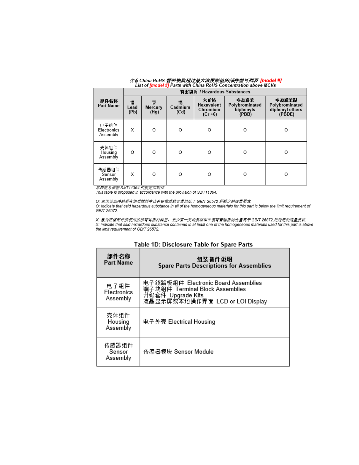
6.11 China RoHS tables
48 GDU-Incus
Page 49

Reference Manual Theory of operation
00809-0100-3003 December 2020
A Theory of operation
The GDU-Incus is omni-directional. Emerson recommends mounting it between 10 and
16 ft. (3 and 5 m) above the area of interest to eliminate ground absorption and
reflections.
Emerson recommends ultrasonically mapping the area where the detector is to be
situated prior to installation or at commissioning while all processes are running to
establish a background noise level for alarm purposes. Set the alarm level above the
background noise level. Contact your Emerson representative for more information
regarding mapping.
The detector responds instantaneously to pressurized gas leaks or other sources of
ultrasonic noise between 25 kHz and 100 kHz. Therefore, Emerson recommends building
in a delay time to the control system or programming it in the detector when using it in
stand-alone mode to prevent spurious alarms. Emerson recommends setting the delay
time at a minimum of 15 seconds, but increase this time in response to the process
located near the detector as shown in Figure 3-2.
Several factors affect the maximum area which can be monitored by a single detector.
These factors include:
• Background (ambient) ultrasound level
• Gas pressure
• Leak size
• Gas temperature
• Environmental conditions
Emerson has formulated a series of calculations that take all of these external factors into
account in order to determine accurate coverage information for most installations.
Contact an Emerson representative to advice on appropriate coverage for each
installation.
Emerson recommends completing a verification test of the GDU-Incus after installation
and in line with existing site maintenance procedures. You can verify the detection
coverage at installation or as part of a maintenance schedule using the GDU-01-TT
Ultrasonic Test Transmitter which electrically replicates the airborne ultrasound generated
from a pressurized gas leak using a piezoelectric disc and can activate alarm conditions
with any ultrasonic gas leak detector. See Spare parts and accessories for a list of spare
parts and accessories or contact an Emerson representative for further details.
Compared to other ultrasonic and traditional forms of detection, the GDU-Incus has the
following advantages:
• Gas does not need to reach the sensor to be detected.
• Unaffected by weather conditions.
• Sensors are unaffected by temperature, pressure, moisture, and contamination build-
up.
• Multiple sensor redundancy in each unit.
Reference Manual 49
Page 50

Theory of operation Reference Manual
December 2020 00809-0100-3003
• Continuous self-test function.
• No calibration required, which results in cost savings over the detector lifecycle.
• Can be remotely tested from up to 26.2 ft. (8 m) distance, saving on maintenance
scaffold costs.
• 4-20 mA current loop with HART® communication as standard, plus relay outputs for
Fault and Alarm conditions.
• Can operate standalone or as part of an interfaced control system.
50 GDU-Incus
Page 51

Reference Manual
00809-0100-3003 December 2020
Reference Manual 51
Page 52

*00809-0100-3003*
00809-0100-3003
Rev. AD
2020
EMERSON AUTOMATION SOLUTIONS
6021 Innovation Blvd.
Shakopee, MN 55379
+1 866 347 3427
+1 952 949 7001
safety.csc@emerson.com
EUROPE
Emerson Automation Solutions
Neuhofstrasse 19a PO Box 1046
CH-6340 Baar
Switzerland
+41 (0) 41 768 6111
+41 (0) 41 768 6300
safety.csc@emerson.com
LinkedIn.com/company/Emerson-Automation-Solutions
Twitter.com/rosemount_news
Facebook.com/Rosemount
Youtube.com/RosemountMeasurement
MIDDLE EAST AND AFRICA
Emerson Automation Solutions
Emerson FZE
Jebel Ali Free Zone
Dubai, United Arab Emirates, P.O. Box 17033
+971 4 811 8100
+971 4 886 5465
safety.csc@emerson.com
©
2020 Emerson. All rights reserved.
ASIA-PACIFIC
Emerson Automation Solutions
1 Pandan Crescent
Singapore 128461
Republic of Singapore
+65 6 777 8211
+65 6 777 0947
safety.csc@emerson.com
 Loading...