

Page 1
Installation and Operation Manual
Dimension
Double-Acting Actuator
Product Data Sheet EHO
March 2015
EHO.01.05.EN, Page 2 of 2, Rev. 0
Part Number: VA001-507-32, Rev. 1
Release: August 2016
Bettis™ EHO (Electro-Hydraulic Operated)
Double-Acting Actuator
Page 2

Installation and Operation Manual
Part Number: VA001-507-32, Rev. 1
Table of Contents
Section 1: Introduction
1.1 Scope .......................................................................................................... 1
1.2 General Information ................................................................................... 1
1.3 Safety Information ...................................................................................... 2
1.4 Abbreviation Definitions ............................................................................. 2
Section 2: Installation
2.1 Preparation ................................................................................................. 4
2.2 Valve Preparation ........................................................................................5
2.3 Actuator Preparation .................................................................................. 5
2.4 Lifting the EHO Actuator ............................................................................. 6
2.5 Installing the EHO Actuator on the Valve ...................................................11
2.6 Setting the Stroke Limit Stops ....................................................................11
2.7 Hydraulic Fluid .......................................................................................... 12
2.8 Accumulator (Optional) ............................................................................ 12
Table of Contents
August 2016
Section 3: Electrical Connections
3.1 Remove Separate Terminal Chamber (STC) Cover ..................................... 17
3.2 Sealing Cable/Conduit Entries ................................................................... 18
3.3 Recommended Terminal Connections ...................................................... 18
3.4 Separate Terminal Chamber (STC) Connections ........................................ 19
3.5 Replace Terminal Chamber Cover ............................................................. 19
3.6 External Earth/Ground Connections .......................................................... 19
3.7 Discrete Controlled Inputs Connection ..................................................... 20
Section 4: Set-up/Start-up Procedure
4.1 Preparation ............................................................................................... 21
4.2 Initial Check of the Unit ............................................................................ 22
4.3 Initial Connections .................................................................................... 22
4.4 Hand Pump ............................................................................................... 22
4.5 Hydraulic Test ........................................................................................... 25
4.6 Check Rotation ......................................................................................... 26
4.7 Limit Switch Adjustment ........................................................................... 27
4.8 Function Test ............................................................................................ 30
4.9 Other Options ........................................................................................... 32
Section 5: Operation
5.1 Hydraulic Power System ........................................................................... 33
5.2 Reservoir ................................................................................................... 33
5.3 Main Components .................................................................................... 33
5.4 Functional Description .............................................................................. 37
Table of Contents
I
Page 3

Table of Contents
August 2016
Installation and Operation Manual
Part Number: VA001-507-32, Rev. 1
Section 6: Pushbutton Module (PBM)
6.1 Selector Knob and Control Pushbuttons ...................................................40
Section 7: Troubleshooting
Section 8: Hazardous Area Classification and SIL Certification
Section 9: Weights and Dimensions
9.1 EHO Standard Double Acting .................................................................... 43
Section 10: Sample Wiring Diagram
10.1 2-Way Electric Powered By an Electro-Hydraulic Power Unit ..................... 44
10.2 2-Way Electric With Emergency Shutdown Feature Powered By an Electro-
Hydraulic Power Unit ................................................................................ 45
II
Table of Contents
Page 4

Installation and Operation Manual
Part Number: VA001-507-32, Rev. 1
Section 1: Introduction
1.1 Scope
This manual is offered as a guide to be used along with locally approved and safe
practices to install, operate, service and maintain the Bettis EHO Actuator. Carefully
follow the instructions in this manual and make sure you install the actuator correctly
and according to your requirements.
1.2 General Information
1.2.1 Overview
The Bettis EHO is a self-contained, quarter-turn, valve actuator that combines proven
technologies from Emerson’s Actuation Technologies. The actuator has been designed
for
critical shutdown applications where reliability is crucial. The EHO utilizes a dependable
spring-return actuator for the Fail-safe stroke combined with an integral hydraulic power
pack and electronic control module.
Section 1: Introduction
August 2016
The EHO accepts a wide range of single-phase, three-phase or DC power sources, also
solar panels are available for areas without electrical power. A hydraulic hand pump can
be used to stroke the actuator during commissioning or in the event of an emergency
power loss.
Electronic modules are contained within an explosion proof, IP68 enclosure and all
electronic components are isolated from the customer connection terminals.
The EHO provides a compact design with actuator and control components that have
been field proven for decades in critical service applications.
1.2.2 Product Attribute
• Easy installation – Bettis™ EHO actuator is a totally self-contained system and
designed for compactness and adaptable to new or existing valves.
• Bettis™ G-Series hydraulic double-acting or spring-return fail-safe actuator
• Shafer™ hydraulic control technology
• EIM™ electronics and communication technology
• Multiple input power options with either AC or DC
• Local lockable Remote/Local/Offline switch
• Local open/close/stop switch
• Partial stroke test
• Fast speed of operation to Fail-safe position if required
• Emergency shutdown – independent safety circuits and solenoid valve
• Dual sealed Separate Terminal Chamber, allows installation wiring to be
performed or fuses to be replaced without exposing control components to
hostile environmental conditions.
Introduction
1
Page 5

Section 1: Introduction
August 2016
• Control enclosure is made of low-copper aluminum alloy, powder-coated, salt
resistant also rated for IP68 ingress protection.
• Hydraulic hand pump manual override
• Accumulators (optional)
• Solar power (optional)
• Operating pressures up to 3000 psi with standard components
• Easy control over actuator stroking speeds – The stroking speed is controlled
through adjustable hydraulic flow control valves. This enables field personnel to
easily adjust actuator stroking speed to comply with field requirements.
1.3 Safety Information
Safety notices in this manual detail precautions the user must take to reduce the risk of
personal injury and damage to the equipment. The user must read these instructions in
their entirety. Failure to observe these safety notices could result in serious bodily injury,
damage to the equipment, void of the warranty. Take special notice of all tags, warning
labels and instructions presented on the actuator. These may provide more specific and
significant information regarding the actuator than this general manual.
Installation and Operation Manual
Part Number: VA001-507-32, Rev. 1
It is the responsibility of the user to ensure proper safety practices are utilized. Always
take necessary precautions and use proper protective equipment when dealing with
compressed gasses, compressed hydraulic fluid, pinch points and electricity.
Safety notices are presented in this manual in three forms (Warning, Caution and Note)
as follows:
WARNING:
Alerts user of potential danger; failure to follow the warning notice could result in
serious personal injury or death.
CAUTION:
Identifies precautions the user must take to avoid personal injury or equipment damage.
NOTE:
Highlights information critical to the user’s understanding of the Bettis EHO valve
actuator installation or operation.
2
Introduction
Page 6

Installation and Operation Manual
Part Number: VA001-507-32, Rev. 1
1.4 Abbreviation Definitions
Abbreviations used in this manual and their definitions are listed in the table below:
Table 1. Abbreviation Definitions
Abbreviation Definition
IOM Installation Operation Manual
SCH Self-Contained Hydraulic
ESD Emergency Shutdown
FS Fail-safe
SR Spring-Return
DA Double-Acting
MAWP Maximum Allowable Working Pressure
MOP Maximum Operating Pressure
STC Separate Terminal Chamber
PBM Pushbutton Module
LDM Local Display Module
RDM Remote Display Module
CBM Circuit Breaker Module
PCB Printed Circuit Board
LS Limit Switch
PS Pressure Switch
NC Normally Closed
NO Normally Open
CCW Counterclockwise
CW Clockwise
OL Overload
PPE Personal Protective Equipment
GA General Arrangement Drawing
Section 1: Introduction
August 2016
Introduction
3
Page 7

Section 2: Installation
August 2016
Section 2: Installation
2.1 Preparation
2.1.1 Delayed Usage
If for any reason the actuator is not to be installed immediately, Bettis recommends the
following procedures. Failure to comply, with recommended procedures, could lead to
actuator malfunction and possibly void the warranty. For storage procedures exceeding
one year, consult Bettis for further recommendations.
As shipped from the factory, the Bettis EHO actuator is an inherently weatherproof unit,
providing that all compartment covers and cable entry plugs remain intact. The actuator
should be immediately stored in a clean, dry warehouse, free from vibration and rapid
temperature changes, until it can be installed and energized.
If the actuator must be stored outside, store it off of the ground at an elevation
sufficient to prevent it from being immersed in water or buried in snow. Check for any
unpainted or exposed metal surfaces and make sure they are protected with a coating
of grease to prevent any corrosion. Cover the actuator to prevent damage from site
debris.
Installation and Operation Manual
Part Number: VA001-507-32, Rev. 1
2.1.2 Tools and Materials Required
To complete these procedures, you will need the following documentation for the
Bettis EHO Actuator and items indicated in the table below:
• General Arrangement Drawing
• Bill of Material
• Hydraulic System Schematic
• System Wiring Diagram
Table 2. Tools and Material Requirements
Tools and Material Requirements
Primary Power Source for the EHO
(check the EHO System Electrical Diagram for requirements)
Supplemental quantity of hydraulic fluid, if needed
(See 2.7, Hydraulic Fluid and EHO specification, for required fluid type)
Nitrogen Source (if an Accumulator is supplied with the EHO)
Hand Tools: complete complement of open end (SAE and metric) wrenches, screw driv-
ers Philips and flat blade and a set of hex wrenches
Chains and lifting straps that are inspected and certified for the weight of the EHO
Actuator (check shipping weights)
Sealant for all cable and conduit entries (approvable by the National Electric Code or
your country standard and applicable local codes)
4
Installation
Page 8

Installation and Operation Manual
Part Number: VA001-507-32, Rev. 1
2.2 Valve Preparation
2.2.1 Remove Valve Gearing if so equipped.
2.2.2 If valve is equipped with stops, remove valve stem extension housing. Examine
the valve stops to ensure no foreign material is present that would restrict
normal travel of the valve. Some valves are equipped with inspection ports in
the valve housing for ease in examining the stops.
2.2.3 Check alignment of stem key slot to the position of the valve. Normally
with the valve in the open position, the key slot is in line with the run of the
pipeline.
With the valve in the closed position, the key slot should be 90° to the run of
the valve.
2.2.4 The EHO Actuator may be mounted to the valve at any time regardless of
whether or not the valve is under pressure.
2.3 Actuator Preparation
Section 2: Installation
August 2016
2.3.1 Once the EHO Actuator is uncrated and cleaned for installation, check to ensure
there will be no interference with piping or other structure when the actuator is
properly mounted to the valve.
NOTE:
At this point, check to see that when the actuator is mounted to the valve and in its final
orientation, the outboard end of the power cylinder positioned below the Hydraulic
Reservoir Breather. If this is not possible, contact Bettis for further instructions on piping
to elevate the breather. See Vertical Mounted Actuator 2.4.4.
2.3.2 Check that all mounting materials such as fasteners, adapters, brackets etc. are
on hand and ready for use.
2.3.3 Check the actuator and valve to see that they are in the same relative position,
that is either open or closed. If the actuator has to be moved, use the hand
pump provided. For hand pump operation, remove the plug in the reservoir and
install the breather (refer to 4.4 Hand Pump Operation).
2.3.4 All spring-return EHO Actuators are supplied with a small accumulator for
protection from thermal-expansion of the hydraulic fluid. This accumulator is
pre charged at the factory and will not need service during installation or startup of the actuator.
CAUTION:
Be aware, while preparing to and lifting the actuator, the Thermal Compensating
Accumulator contains high-pressure nitrogen. Use care not to damage the accumulator
or its attachments.
Installation
5
Page 9
Section 2: Installation
August 2016
2.4 Lifting the EHO Actuator
NOTE:
All Bettis EHO G-Series Considerations
When handling any EHO G-Series, be aware of tubing, accessories, hand pump,
accumulators, Pushbutton module and control enclosures. Straps and chains can become
entangled and cause damage to these components. Never use chains on the spring
cartridge as it may warp and cause the actuator not to function correctly or may cause
personal injury.
NOTE:
Do not use hydraulic tubing and electrical cable for lifting.
CAUTION:
Installation and Operation Manual
Part Number: VA001-507-32, Rev. 1
Be sure to use appropriately rated crane/hoist and straps/chains to raise and lower
the actuator.
2.4.1 G01X – G2 and All E-Series Actuators
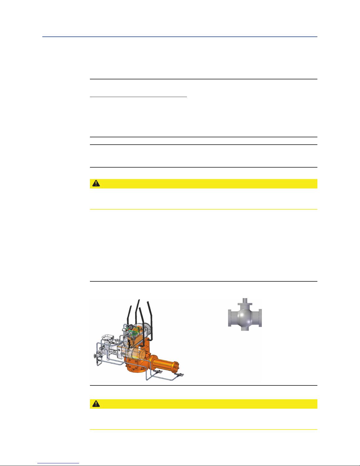
2.4.1.1
Figure 1 G01 – G2 and all E-Series Actuators with Horizontal Pipeline
and Vertical Stem
Horizontal Pipeline Vertical Stem
The small G-Series and all E-Series actuators mounting on a horizontal
pipeline with a vertical valve stem should be supported under the
“C” bracket and a two-point attachment for balance. A strap may be
attached to the stabilization tab on the spring module to balance the
unit while lifting. The weight of the actuator must be supported at the
“C” bracket, not the stabilization tab. See Figure 1.
CAUTION:
Never lift the actuator with a valve attached. Always handle actuator/valve assemblies
by attaching lifting equipment to the valve only.
6
Installation
Page 10
Installation and Operation Manual
Part Number: VA001-507-32, Rev. 1
Section 2: Installation
August 2016
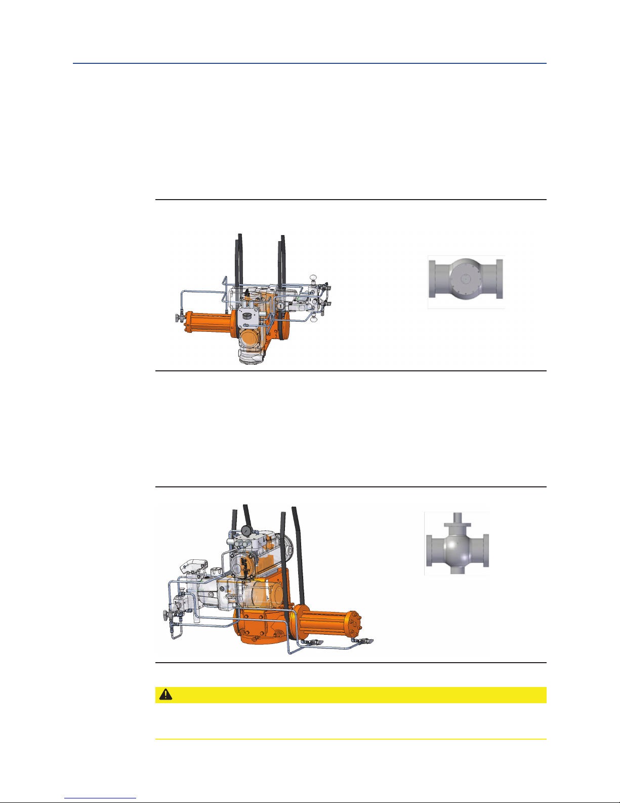
2.4.1.2
Horizontal Pipeline Horizontal Stem
The small G-Series and all E-Series actuators mounting on a horizontal
pipeline with a horizontal valve stem should be supported on
the ends of the drive module. A strap may be attached to the
stabilization tab on the spring module to balance the unit while
lifting. The weight of the actuator must be supported at the drive
module, not the stabilization tab. See Figure 2.
Figure 2 G01 – G3 and all E-Series Actuators with Horizontal
Pipeline and Horizontal Stem
2.4.2 G3-Series Actuators
2.4.2.1
Horizontal Pipeline Vertical Stem
The G3-Series actuator mounting on a horizontal pipeline with a
vertical valve stem should be supported at the ends of the drive
module. A strap may be attached to the stabilization tab on the spring
module to balance the unit while lifting. The weight of the actuator
must be supported at the drive module, not the stabilization tab. See
Figure 3.
Installation
Figure 3 G3 with a Horizontal Pipeline and Vertical Stem
CAUTION:
Never lift the actuator with a valve attached. Always handle actuator/valve assemblies
by attaching lifting equipment to the valve only.
7
Page 11
Section 2: Installation
August 2016
Installation and Operation Manual
Part Number: VA001-507-32, Rev. 1
2.4.2.2
Horizontal Pipeline Vertical Stem
The G3-Series actuator mounting on a horizontal pipeline with a
horizontal valve stem should be supported on the ends of the drive
module. A strap may be attached to the stabilization tab on the
spring module to balance the unit while lifting. The weight of the
actuator must be supported at the drive module, not the stabilization
tab. Be sure to use appropriately rated crane/hoist and straps/chains
to raise and lower the actuator. See Figure 2 above.
2.4.3 G4 – G7 Series Actuators
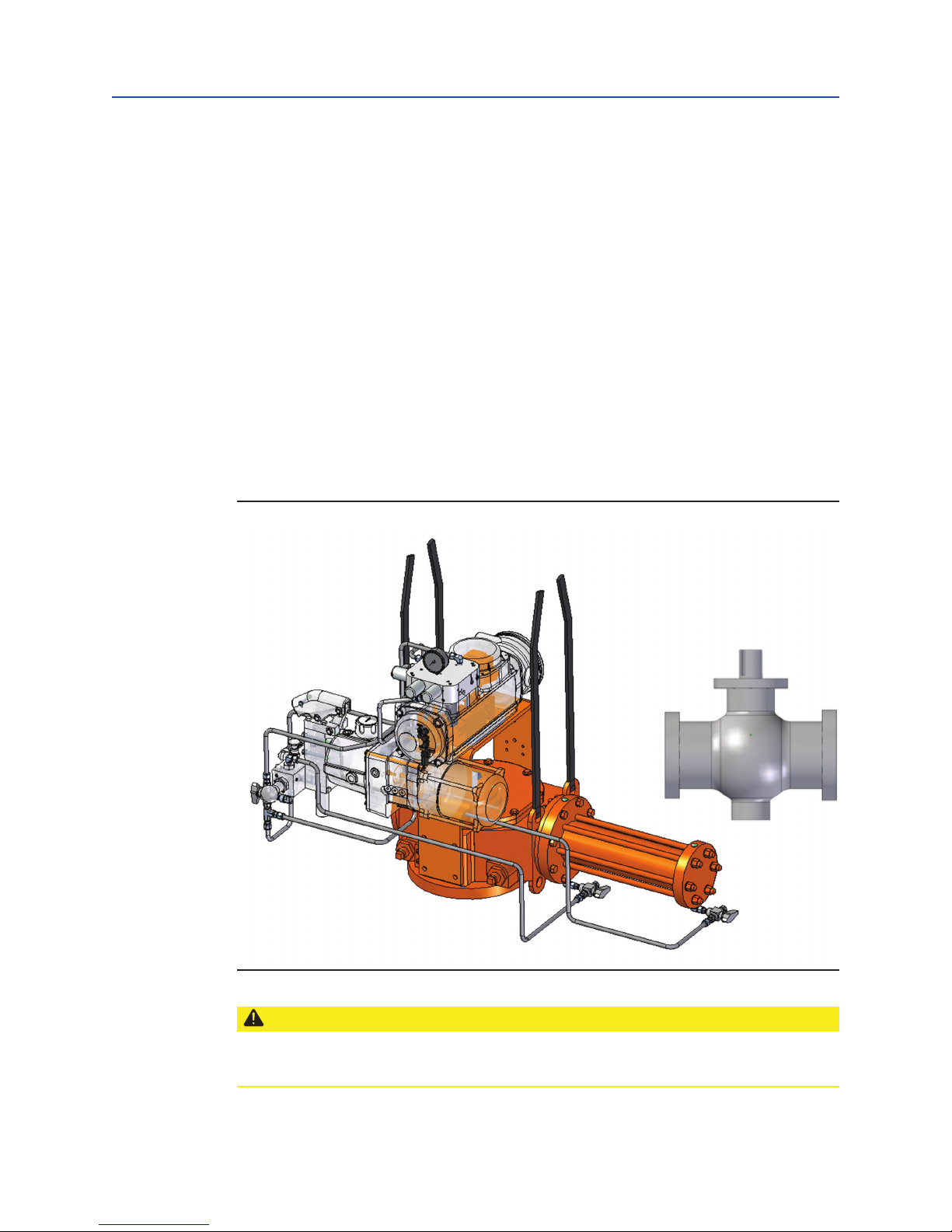
2.4.3.1
Horizontal Pipeline Vertical Stem
The G4 – G7 Series actuators mounting on a horizontal pipeline with
a vertical valve stem should be supported using the lift lugs attached
to the drive module. A strap may be attached to the stabilization
tab on spring module to balance the unit while lifting. The weight of
the actuator must be supported by the lugs at drive module, not the
stabilization tab.
See Figure 4.
Figure 4 G4 – G7 with a Horizontal Pipeline and Vertical Stem
CAUTION:
Never lift the actuator with a valve attached. Always handle actuator/valve assemblies
by attaching lifting equipment to the valve only.
8
Installation
Page 12

Installation and Operation Manual
Part Number: VA001-507-32, Rev. 1
Section 2: Installation
August 2016
2.4.3.2
Horizontal Pipeline Horizontal Stem
The G4 – G7 Series actuators mounting on a horizontal pipeline with
a vertical valve stem should be supported using the lift lugs attached
to the drive module. A strap may be attached to the stabilization
tab on spring module to balance the unit while lifting. The weight of
the actuator must be supported by the lugs at drive module, not the
stabilization tab.
See Figure 5.
Figure 5 G4 – G7 with a Horizontal Pipeline and Horizontal Stem
CAUTION:
Never lift the actuator with a valve attached. Always handle actuator/valve assemblies
by attaching lifting equipment to the valve only.
Installation
9
Page 13

Section 2: Installation
August 2016
2.4.4 Mounting the Actuator in a Vertical Orientation on a Horizontal Stem
When mounting an Bettis EHO Actuator in a vertical orientation, the Spring Module
must be positioned up. The actuator may be supported by using two straps in the
configuration shown in Figure 6. A third strap or small chain may be attached to the
stabilization tab on spring module to balance the unit while lifting. The weight of the
actuator must be supported by the straps running over the spring module and under the
drive module flange.
Figure 6 Vertical Actuator Lift
Installation and Operation Manual
Part Number: VA001-507-32, Rev. 1
CAUTION:
Never lift the actuator with a valve attached. Always handle actuator/valve assemblies
by attaching lifting equipment to the valve only.
NOTE:
When a vertical EHO Actuator is mounted to the valve, and in its final orientation, the
spring module must be up and outboard end of the power cylinder positioned below
the Hydraulic Reservoir Breather. If not possible, contact Bettis for further instructions
on piping to elevate the breather.
10
Installation
Page 14

Installation and Operation Manual
Part Number: VA001-507-32, Rev. 1
Section 2: Installation
2.5 Installing the EHO Actuator on the Valve
The actuator will be bolt-mounted directly to a bracket or adaptor that will be bolted
securely to the mounting flange top works of the valve.
2.5.1 Check to see that the dimensions of the bracket or adaptor are suitable for use
with the valve mounting flange and stem.
2.5.2 Check valve direction of rotation and the actuator direction of rotation to see
they match (for example: CW = close, CCW = open).
2.5.3 Check to see the actuator and valve are in the same relative position (see 2.3.3).
2.5.4 Check all mounting surfaces, they must be clean and free of debris to permit
proper fit up.
2.5.5 Prior to mounting, grease the coupling bore and the bore of the actuator.
NOTE:
Do not apply grease to the mounting flange surfaces on the valve or the adaptor.
August 2016
2.5.6 Install the stem key and grease it (keys may be held in place with tape).
2.5.7 Install the coupling onto the stem and stem key.
2.5.8 Install the coupling key and grease it.
2.5.9 Carefully align the coupling and key to the bore and keyway in the actuator
and slide the actuator onto the coupling until the adapter (bracket) bottoms
out on the valve bonnet.
NOTE:
Ensure the adapter seats out on the valve bonnet, without interference, before
installing fasteners.
2.5.10 Use the required fasteners to firmly attach the adapter to the valve bonnet.
Tighten the fasteners to their manufacturer’s recommended maximum torque
(dry or lubricated).
2.6 Setting the Stroke Limit Stops
2.6.1 The Bettis G-Series is provided with bi-directional travel stops allowing 80° to
100° total travel (+/- 5° adjustment at each end of the 90° stroke).
2.6.2 Actuators are shipped from the factory with the travel stops adjusted for
approximately 90° rotation. Generally, it is necessary to make slight travel
stop adjustments once the actuator is installed on the valve. Refer to the valve
manufacturer's recommendations for specific requirements.
2.6.3 When the valve has internal stops, the actuator stops must be set so that the
load is applied to them, not the valve stops.
2.6.4 If adjustment is required, use the hand pump to move the actuator off the stop
at the closed position before attempting to turn the adjusting screw (refer to
4.4, Hand Pump Operation).
Installation
11
Page 15

Section 2: Installation
August 2016
CAUTION:
Always use the hand pump to move the actuator off the stop before attempting to turn
the adjusting screw.
2.6.5 With the closed position stop set, use the hand pump to move the actuator
to the other end of the stroke and check the stop position. If adjustment is
required, slowly open Manual Bypass Valve (Lockable) (19) just enough to allow
the actuator to spring-return off the stop before adjusting.
2.7 Hydraulic Fluid
Bettis Electro-Hydraulic Operated actuators are shipped with the reservoir filled to
operation level. Before commissioning and periodically afterwards, check to see the
fluid level is correct. The oil fill cap is provided with a dipstick marked with a green and a
red mark. When the optional accumulator is drained of fluid and the actuator is at Failsafe Position, the oil should be at the green mark. The reservoir also has a sight gauge
for the purpose of seeing fluid is present. Should fluid need to be added or replaced, use
only factory approved hydraulic fluid.
Installation and Operation Manual
Part Number: VA001-507-32, Rev. 1
This specification covers hydraulic fluids which are approved by engineering for use in
Bettis Electro-Hydraulic Operated actuator in a temperature range from -40°F to 140°F
(-40°C to 60°C).
2.7.1 Approved Fluids
•
•
Although other brands of fluid matching the same specifications may be used, to
maintain the warranty and ensure trouble free operation, always check with the factory
before substituting any other fluid.
Standard Fluid [use with -20°F to 140°F (-29°C to 60°C) applications]
— ConocoPhillips Megaflow™ AW HVI Hydraulic Oil 22
— Shell Tellus S2 V 22
— Mobil DTE 10 Excel™ 22
Low Temperature Fluid [use with -40°F to 140°F (-40°C to 60°C) applications
— Mobil Univis™ HVI 13
12
Installation
Page 16

Installation and Operation Manual
Part Number: VA001-507-32, Rev. 1
2.8 Accumulator (Optional)
2.8.1 Introduction
The Bettis EHO Actuator may be equipped with an accumulator to enable manual
operation of the actuator if there is a loss of electrical power. Accumulators always
have the nitrogen pressure drained for shipping (except for Thermal Compensating
Accumulator see 2.3.4).
NOTE:
When using this procedure, refer to the Bettis EHO Actuator General Arrangement
drawing and Hydraulic Schematic for the unit being worked on. (Schematic below is for
illustration only.)
WARNING:
Section 2: Installation
August 2016
This unit contains high-pressure hydraulic fluid and nitrogen gas. Exercise caution when
performing any type of maintenance. Wear proper safety attire and required personal
protective equipment, including safety glasses.
2.8.2 Accumulator Pre-charge
a. Locate Isolation Valve (F) (Nitrogen Blow Down and Fill) for the
Customer Nitrogen Fill Connection, called out on the General
Arrangement Drawing and Hydraulic Schematic (see illustration below).
b. Close the Isolation Valve (F) and remove the pipe plug from the adaptor.
NOTE:
The Adaptor is tapped with a 1/4-NPTF thread.
c. Ensure 3-way Isolation Valve (D) is turned fully counterclockwise.
d. Slowly open Isolation Valve (Accumulator drain) (E) and drain all the
fluid back to the reservoir.
e. Connect a nitrogen supply to the Customer Nitrogen Fill Connection at
Isolation Valve (F).
f. Open the Isolation Valve (F) (Nitrogen Blow Down and Fill) and
charge the Accumulator, to the pre-charge pressure as specified by
the Pressure versus Temperature Graph on the General Arrangement
Drawing.
NOTE:
For temperatures, which do not appear on the graph, the formula to calculate the
pre-charge pressure shown on the General Arrangement Picture Assembly should be
used.
Installation
13
Page 17

Section 2: Installation
August 2016
NOTE:
Recheck the pre-charge pressure after a time interval sufficient to insure the nitrogen
pressure is equal to the ambient temperature (a minimum of 4 hours). Adjust the
pre-charge pressure as required to conform to the Pressure versus Temperature graph.
NOTE:
The straight thread plug must be installed, after filling is complete, to prevent
accidental leakage of nitrogen from Isolation Valve (25).
Installation and Operation Manual
Part Number: VA001-507-32, Rev. 1
g. After the nitrogen filling is complete, close the Isolation Valve (F)
(Nitrogen Blow Down and Fill).
h. Disconnect the nitrogen supply and remove the female pipe adaptor
from Isolation Valve (F).
i. Install the straight thread plug and O-ring, shipped as an accessory, into
Isolation Valve (F).
j. Close Isolation Valve (24).
Figure 7 Typical EHO Optional Accumulator System
G
H
C
F
B
D
I
E
14
A
Installation
Page 18

Installation and Operation Manual
Part Number: VA001-507-32, Rev. 1
Table 3. Typical EHO Optional Accumulator System
Part Number Part Name
A Reservoirs
B Accumulator
C Nitrogen Relief Valve
D 3-way Isolation Valve
E Isolation Valve (Accumulator Drain)
F Isolation Valve (Nitrogen Blow Down and Fill)
G Nitrogen Pressure Gauge
H Nitrogen Gauge Isolation Valve
I Speed Control
2.8.3 Pre-charge Verification
Check the nitrogen pre-charge in the accumulator periodically to ensure the accumulator is at full potential. Follow the steps below and record final readings for reference.
a. Shut off the hydraulic power supply to the accumulator.
b. Ensure 3-way Isolation Valve (D) is turned fully counterclockwise.
c. Slowly open Isolation Valve (Accumulator drain) (E) and drain all the
d. Read the pressure at the nitrogen pressure gauge (G) and compare it to
e. If the pre-charge is low, add nitrogen to increase the pressure to
f. Record Information below.
g. With bypass valve closed, reconnect the hydraulic power supply and
h. Check the entire nitrogen circuit for leaks using a liquid leak detector
Section 2: Installation
August 2016
fluid back to the reservoir.
the Oil/Temperature Chart shown on the General Assembly Drawing for
the job being checked.
the requirements listed on the GA Oil/Temperature Chart. See 2.8.2,
Accumulator Pre-charge, if the pre-charge is high relieve pressure to
equal the GA Oil/Temperature Chart.
bring the accumulator back up to full pressure.
such as Snoop (manufactured by Swagelok). As the unit is self-contained,
only a zero leak rate is acceptable. Corrective action must be taken for
any leaks found.
WARNING:
This unit contains high-pressure hydraulic fluid and nitrogen gas. Exercise caution when
performing any type of maintenance. Wear proper safety attire and required personal
protective equipment, including safety glasses. Ensure the accumulator has been
drained of all hydraulic and nitrogen pressure before attempting any repair.
Installation
15
Page 19

Section 2: Installation
August 2016
2.8.4 Nitrogen Pre-charge Maintenance Record
Serial Number: _____________________________
Tag Number: _______________________________
Date
Initial
Pre-charge
GA Chart
Requirement
Installation and Operation Manual
Part Number: VA001-507-32, Rev. 1
Final
Pre-charge
Nitrogen
Leak Test
Signed
16
Installation
Page 20
Installation and Operation Manual
Part Number: VA001-507-32, Rev. 1
Section 3: Electrical Connections
Section 3: Electrical Connections
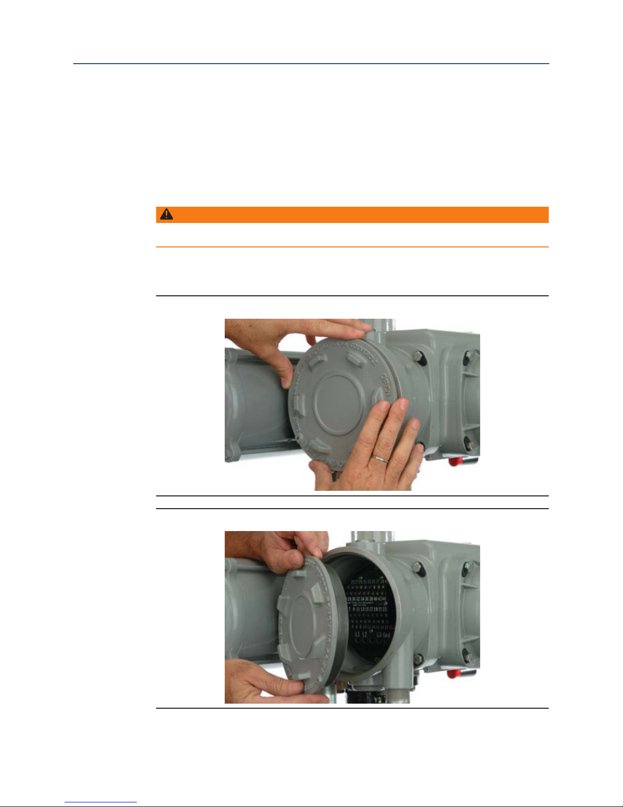
3.1 Remove Separate Terminal Chamber (STC)
Cover
WARNING:
Always verify electrical power is disconnected before removing the STC cover.
3.1.1 Remove cover with a strap wrench, drift, or pinch bar by rotating the
cover counterclockwise.
Figure 8 Remove STC Cover Turning Counterclockwise
May 2016
Figure 9 Lay Cover Aside
Electrical Connections
17
Page 21

Section 3: Electrical Connections
May 2016
Installation and Operation Manual
Part Number: VA001-507-32, Rev. 1
3.2 Sealing Cable/Conduit Entries
Seal the cable and conduit entries in accordance with the National Electric Code or your
country standard and applicable local codes. All conduit entries should be sealed against
the site environment. All unused conduit entries must be sealed with threaded metal
plugs.
3.3 Recommended Terminal Connections
The Bettis Electro-Hydraulic actuator terminal block connectors are wire binding screw
connectors with rising captive plates. Connections can be made one of three ways:
• Strip and connect bare wire
• Strip and install wire ferrule
• Strip and install crimp-on insulated or non-insulated ring or fork-tongue connec-
tors for either M3 control signal terminal block screws or M4 power terminal
screws.
3.3.1 Loosen terminal block connectors L1, L2, L3 and GND screws with a common or
Phillips head screwdriver.
3.3.2 If bare wire is being used, strip insulation a maximum of 1/2 inch (12mm).
3.3.3 Insert wire or wire lug under terminal block connector screw clamps and
tighten.
Figure 10 Power Terminal Connection Length of Bare Wire Strip
Figure 11 Control Terminal Connection Length of Bare Wire Strip
18
Electrical Connections
Page 22

Installation and Operation Manual
Part Number: VA001-507-32, Rev. 1
Section 3: Electrical Connections
May 2016
3.4 Separate Terminal Chamber (STC) Connections
3.4.1 Connect the main power supply cables, including an Earth/Ground
(refer to the job specific Wiring Diagram).
3.4.2 Use the barrier strip clamp screws to connect the control wiring
(refer to the job specific Wiring Diagram).
3.4.3 Ensure all connections are hand tight, including any unused terminals.
NOTE:
The main power supply and ground wire connections are screw size M4.
The control connection screw size is M3.
3.5 Replace Terminal Chamber Cover
3.5.1 Clean electrical enclosure threads thoroughly and lightly grease with dielectric
grease before closing.
3.5.2 Replace the cover by reversing the order of the steps to remove the cover.
3.6 External Earth/Ground Connections
External connection points are provided on the operator for attaching earth/ground in
accordance with local electric codes for installation cables.
Connect the external earth/ground connection as follows.
3.6.1 Using a slotted tip screwdriver, back out the 5/16-inch set screw.
3.6.2 Connect 14 AWG or larger earth/ground wire, tighten setscrew.
Figure 12 External Earth/Ground Connection
Electrical Connections
19
Page 23

Section 3: Electrical Connections
May 2016
Installation and Operation Manual
Part Number: VA001-507-32, Rev. 1
3.7 Discrete Controlled Inputs Connection
The actuator can be controlled by discrete inputs: two-wire control, three-wire
control, four-wire valve control. Connect the power for these discrete inputs as
detailed in
Figures 13 and 14. See Section 3.3, Electrical Connections, for general electrical
connection requirements.
Figure 13 Control Input Wiring – Internal Power Supply
Figure 14 Control Input Wiring – External Power Supply 24 VDC
20
Electrical Connections
Page 24

Installation and Operation Manual
Part Number: VA001-507-32, Rev. 1
Section 4: Set-up/Start-up Procedure
Section 4: Set-up/Start-up Procedure
In addition to this set-up/start-up procedure, the following documentation will be
necessary to fulfill all set-up and start-up requirements.
1. General Arrangement drawing
2. Bill of Material
3. Schematic drawing
4. Wiring Diagram drawing
When using these instructions, refer to the schematic diagram, wiring diagram, general
arrangement drawings for the Bettis EHO and the certified bills of material.
Numbers in [ ] correspond to components labeled on the wiring diagram. Numbers in
( ) correspond to components labeled on the schematic diagram. Information in (( )) is
descriptive.
When the Bettis EHO is delivered to the job site, it has been both pressure and function
tested. The oil reservoir was filled to operation level when it shipped from factory.
August 2016
4.1 Preparation
4.1.1 Safety First
Hydraulic Pressure
WARNING:
Ensure that test personnel and witnesses are properly informed of the hazards involved
with high pressures and the proper safety barriers are employed.
Never check for leakage using your fingers or hands. Fluid under high pressure can inject
into the skin and cause severe damage or death. Always use an implement such as a piece
of paper.
Safety Equipment
WARNING:
All personnel in the testing area must always wear safety glasses.
Set-up/Start-up Procedure
21
Page 25

Section 4: Set-up/Start-up Procedure
August 2016
4.1.2 Material and Equipment for Start-up and Set-up
To complete this procedure, you will also need the following materials and equipment:
Table 4. Required Material and Equipment
Required Material and Equipment
Miscellaneous fittings, adapters and Hand Tools: complete complement of open end
((SAE and metric)) wrenches, screw drivers Philips and flat blade and a set of hex
wrenches
Primary Power Source for the EHO
((check the EHO System Electrical Diagram for requirements))
Supplemental quantity of hydraulic fluid, if needed
((See 2.6, Hydraulic Fluid, and EHO specification for required fluid type))
Nitrogen Source ((if an Accumulator is supplied with the EHO))
4.2 Initial Check of the Unit
Installation and Operation Manual
Part Number: VA001-507-32, Rev. 1
NOTE:
The components referenced below are referencing to schematic found in section 10.2.
and is for illustration purposes only. When using this procedure refer to the Bettis EHO
Actuator General Arrangement Drawing and Hydraulic Schematic for the unit being
worked on.
4.2.1 Check to ensure all hydraulic tube fittings are tight. Vibration during shipment
may have loosened connections.
4.2.2 Visually inspect the unit to make sure tubing, hand valves, gauges and other
equipment have not been damaged.
4.2.3 Using the Schematic drawing, verify that the Flow Control Valves (7) are fully
opened ((turn stem completely counterclockwise)).
4.2.4 Ensure Isolation Valve (Accumulator drain) (24) is closed ((if applicable)).
4.2.5 Ensure Isolation Valve (Nitrogen Blow Down and Fill) (25) is closed ((if
applicable)).
4.3 Initial Connections
Electrical connections should have been made to the STC (Separate Terminal Chamber).
If power is not connected, follow the instructions under Section 3, Electrical Connections,
before continuing. If an ((optional)) Circuit Breaker Module is provided, ensure it is turned to
OFF.
CAUTION:
Before the actuator is stroked, check to see it has been filled with fluid to the proper
level. ((See 2.7, Hydraulic Fluid.))
22
Set-up/Start-up Procedure
Page 26

Installation and Operation Manual
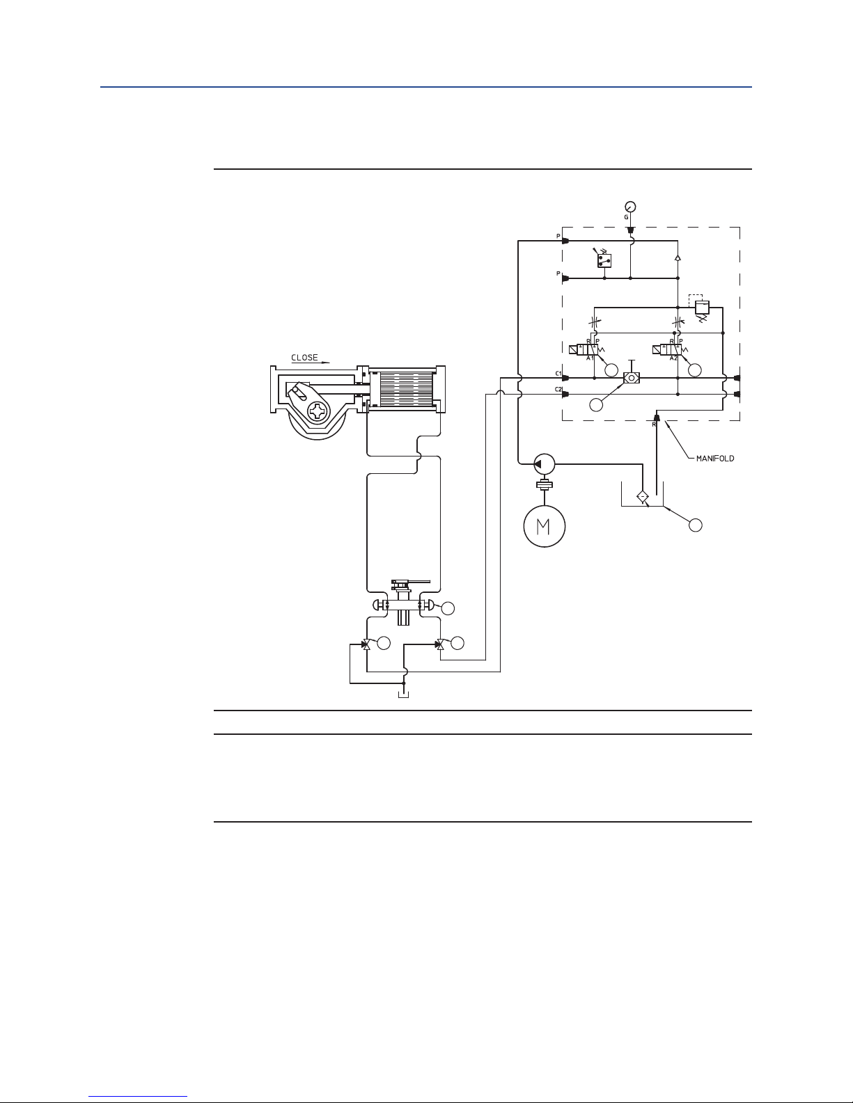
(M) Hand Pump Selection Valves
(L) Hand Pump
(J) Opening Solenoid
(K) Closing Solenoid
Part Number: VA001-507-32, Rev. 1
4.4 Hand Pump
4.4.1 2-Way Remote Electric without ESD solenoid function
NOTE:
Hand Pump Isolation Valve (8)
The components referenced below are referencing Schematic 4.4.1. and is for
illustration purposes only. When using this procedure refer to the Bettis EHO Actuator
General Arrangement Drawing and Hydraulic Schematic for the unit being worked on.
4.4.1.1 Check the Reservoir (I) to see the hydraulic is at the proper level.
4.4.1.2 Rotate downward in the horizontal position both Hand Pump Selector
Valves (M).
4.4.1.3 Select and push inward the open or close knob located on the Hand
Pump Selector Manifold (L).
4.4.1.4 Use supplied Hand Pump Handle to discharge hydraulic fluid into the
open or close side of the actuator cylinder.
4.4.1.5 Continue hand pumping until the actuator completes the open or
close stroke and contacts the actuators adjustable end stops.
4.4.1.6 Once completion of the Hand Pumping operation, push the Pump ByPass Valve located on the top of the Hand Pump Selector Manifold (L)
and pull the pump handle downward retracting the pump ram into the
pump body.
4.4.1.7 Rotate both Hand Pump Selector Valves back into the upward vertical
position.
4.4.1.8 Check the Reservoir (I) to see the hydraulic fluid is at the proper level.
4.4.2 2-Way Remote Electric with an ESD solenoid function
Section 4: Set-up/Start-up Procedure
August 2016
Figure 15 2-Way Remote Electric Without an ESD Solenoid Function Schematic
Set-up/Start-up Procedure
J
L
M
M
K
I
23
Page 27

Section 4: Set-up/Start-up Procedure
August 2016
NOTE:
The components referenced below are referencing Schematic 4.4.2. and is for
illustration purposes only. When using this procedure refer to the Bettis EHO Actuator
General Arrangement Drawing and Hydraulic Schematic for the unit being worked on.
4.4.2.1 Check the Reservoir (I) to see the hydraulic is at the proper level.
4.4.2.2 Close Hand Pump Isolation Valve (O)
4.4.2.3 Rotate downward in the horizontal position both Hand Pump Selector
Valves (M).
4.4.2.4 Select and push inward the open or close knob located on the Hand
Pump Selectoranifold (L).
4.4.2.5 Use supplied Hand Pump Handle to discharge hydraulic fluid into the
open or close side of the actuator cylinder.
4.4.2.6 Continue hand pumping until the actuator completes the open or close
stroke and contacts the actuators adjustable end stops.
4.4.2.7 After completion of the Hand Pumping operation, push the Pump ByPass Valve located on the top of the Hand Pump Selector Manifold (L)
and pull the pump handle downward retracting the pump ram into the
pump body.
4.4.2.8 Rotate both Hand Pump Selector Valves (M) back into the upward
vertical position.
4.4.2.9 Check the Reservoir (I) to see the hydraulic fluid is at the proper level.
4.4.2.10 Once the ESD solenoid signal is re-established, slowly open Hand Pump
Isolation Valve (O).
Installation and Operation Manual
Part Number: VA001-507-32, Rev. 1
Figure 16 2-Way Remote Electric With an ESD Solenoid Function Schematic
N
H
J
Y
L
M M
K
(L) Hand Pump Selector
(M) Hand Pump Selection Valves
(H) Accumulator Isolation Valve(Optional)
(N) Accumulator Isolation Valve(Optional)
(J) Opening Solenoid
(K) Closing Solenoid
(O) Hand Pump Isolation Valve
(P) ESD Solenoid Valve(Optional)
O
P
24
Set-up/Start-up Procedure
Page 28

Installation and Operation Manual
(A) Pressure Gauge(Optional)
(B) Nitrogen Relief Valve(Optional)
(D) Isolation Valve(Optional)
(E) Hydraulic Accumulator With Nitrogen Blanket
Charge(Optional)
(H) Accumulator Isolation Valve(Optional)
(N) Accumulator Isolation Valve(Optional)
(R) Pressure Switch
(Q) Hydraulic Pressure Gauge
(S) Pressure Transmitter(Optional)
(T) Check Valve
(V) Adjustable Flow Controls
(U) Relief Valve
(O) Hand Pump Isolation Valve(Optional)
(W) Bettis G-series Double Acting Actuator
(AB) Pressure Transmitter(Optional)
(J) Opening Solenoid
(K) Closing Solenoid
(P) ESD Solenoid Valve(Optional)
(X) Shuttle Valve(Optional)
(AC) Shuttle Valve(Optional)
(Y) Hydraulic Pump
(AD) Accumulator override valve to open(Optional)
(AE) Accumulator override valve to close(Optional)
(Z) Electric Motor
(AA) Suction Strainer
(I) Fluid Reservoir
(L) Hand Pump
(M) Hand Pump Selection Valves
Part Number: VA001-507-32, Rev. 1
4.4.3 Manual Open or Close with Accumulator Override feature (Optional)
NOTE:
The components referenced below are referencing Schematic 4.4.2. and is for
illustration purposes only. When using this procedure refer to the Bettis EHO Actuator
General Arrangement Drawing and Hydraulic Schematic for the unit being worked on.
4.4.3.1 Select and slowly open the Accumulator override Isolation Valve
4.4.3.2 After completion of the Accumulator manual override stroke, return
Figure 17 2-Way Remote Electric With Emergency Shutdown Feature Powered
by an Electro-hydraulic power unit
Section 4: Set-up/Start-up Procedure
August 2016
(AD) for actuator open stroke and (AE) for actuator closing stroke.
The Isolation Valve is in the actuator stroking position when rotated
downward to the horizontal position.
the Isolation Valve (AD) or (AE) to the upward vertical position.
A
B
D
4.5 Hydraulic Test
Q
E
N
H
W
AD AE
L
M M
R
V
J
X
Y
AA
Z
S
T
U
O
K
I
P
AC
The system has been hydrostatic and function tested at the factory before shipping. This
test is to discover if any leaks have developed in the hydraulic fittings during shipping.
NOTE:
The components referenced below are referencing Schematic 4.4.2. and is for
illustration purposes only. When using this procedure refer to the Bettis EHO Actuator
General Arrangement Drawing and Hydraulic Schematic for the unit being worked on.
Set-up/Start-up Procedure
25
Page 29

Section 4: Set-up/Start-up Procedure
August 2016
4.5.1 Rotate both Hand Pump Isolation Valves (O) to the downward horizontal
position.
4.5.2 Select and push inward the open or close knob located on the Hand Pump
Selector Manifold (L).
4.5.3 Use supplied Hand Pump Handle to discharge hydraulic fluid into the open or
close side of the actuator cylinder.
4.5.4 Once the actuator is fully stroked and makes contact with the actuators
adjustable stops, observe if any leakage is detected at any tube fittings or port
connections from the Hand Pump to the Actuators operating ports.
4.5.5 Push the Pump By-Pass Valve located on the top of the Hand Pump Selector
Manifold (L) and pull the pump handle downward retracting the pump ram into
the pump body.
4.5.6 Select and push inward the opposite open or close knob located on the Hand
Pump Selector Manifold (L).
4.5.7 Repeat steps 4.5.3 thru 4.5.5
4.5.8 Rotate both Hand Pump Selector Valves (M) back into the upward vertical
position.
Installation and Operation Manual
Part Number: VA001-507-32, Rev. 1
4.6 Check Rotation
NOTE:
The components referenced below are referencing to schematic found in section 10.2.
and is for illustration purposes only. When using this procedure refer to the Bettis EHO
Actuator General Arrangement Drawing and Hydraulic Schematic for the unit being
worked on.
4.6.1 Turn on the electrical supply to the unit. If an ((optional)) Circuit Breaker Module
is supplied, turn the Circuit Breaker to ON.
4.6.2 Turn the LOCAL-OFF-REMOTE selector switch to LOCAL.
4.6.3 Ensure Flow Control Valves (V) are adjusted fully counterclockwise for maximum
flow.
4.6.4 Open inspection port on side of unit to observe the rotation of the motor/pump
shaft.
Figure 18 Inspection Port for Motor Rotation
26
Set-up/Start-up Procedure
Page 30
Installation and Operation Manual
Part Number: VA001-507-32, Rev. 1
4.6.5 While observing the inspection port, for motor rotation, push and release the
OPEN/CLOSE PUSHBUTTON to Power Stroke the actuator and immediately push
the STOP Pushbutton. Motor rotation should be counterclockwise when looking
at the back of the motor.
4.6.6 If needed, correct motor rotation.
NOTE:
If the EHO Actuator is supplied with optional ESD, before operating a motor-powered
stroke, a customer supplied ESD signal must be present and Solenoid Valve (P)
energized.
4.6.7 Push and release the OPEN/CLOSE PUSHBUTTON to Power Stroke the actuator.
The Electric Motor (Z) will start to run driving Hydraulic Pump (Y). The
Hydraulic Pump (Y) draws fluid from Reservoir (I) and pushes it into the Bettis
G-series hydraulic cylinder (W).
4.6.8 Shut off the electrical power going to the unit, if an (optional) Circuit Breaker
Module is supplied, turn the Circuit Breaker to OFF.
Section 4: Set-up/Start-up Procedure
August 2016
4.7 Limit Switch Adjustment
4.7.1 To complete limit switch adjustment, the actuator will need to be stroked from
a fully closed position to a fully open position etc. several times. In the following
instructions, the electric motor is used to Power Stroke the actuator. If it is not
safe or possible to use the electric motor at this time, use the Hand pump to
Power Stroke the actuator.
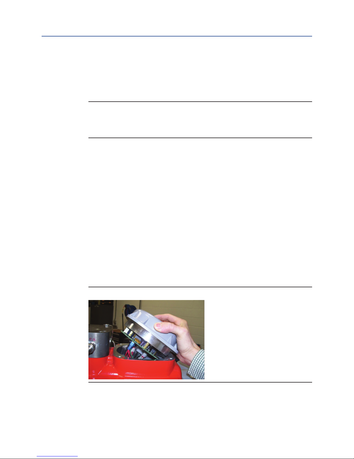
4.7.2 The limit switch adjustments are found in a covered compartment in line with
the valve stem and on the opposite side of the control box. Remove the limit
switch compartment cover by loosening the four corner bolts retaining it.
All covers have tapped holes for jackscrews to aid in removing the cover. Use
the retaining screws in these holes to lift the cover evenly at each corner. Use
caution to not allow the cover to bind during removal.
Figure 19 Remove Cover for Limit Switch Chamber
Set-up/Start-up Procedure
27
Page 31

Section 4: Set-up/Start-up Procedure
August 2016
WARNING:
If the actuator is being installed in a hazardous area, use extreme care. This procedure
requires the limit switch cover to be open while electrical power is connected to the unit.
Follow these steps only when the atmosphere is free of explosive gases.
4.7.3 Close Limit Switch Adjustment
4.7.3.1 The Open and Close Limit Switches, shown in Figure 20, are operated
by targets mounted in a plastic disk that rotates with the actuator
stroke. To adjust a Target, push down on it and slide it in a clockwise or
counterclockwise direction.
Figure 20 View of Limit Switch Targets
Installation and Operation Manual
Part Number: VA001-507-32, Rev. 1
Limit Switch #1 Target
NOTE:
The Switch Targets will be labeled to identify the switch they operate.
4.7.3.2 With the actuator in the Close Position, rotated fully clockwise, the
Target for CLOSE LS-2 will need to be adjusted.
4.7.3.3 Reconnect electrical power to the unit.
4.7.3.4 Push down on the Target for CLOSE LS-2 and move clockwise until it is
off of the switch in the clockwise direction. Both the OPEN and the
CLOSE lights on the PBM ((Pushbutton Module)) should be
illuminated
at this point.
4.7.3.5 Now, push down and slide the Target for CLOSE LS-2 counterclockwise
until the OPEN light just goes out. It is important to always adjust a
Target in the opposing direction of the valve travel to get an accurate
setting.
28
Set-up/Start-up Procedure
Page 32

Installation and Operation Manual
Part Number: VA001-507-32, Rev. 1
4.7.3.6 With the LOCAL – OFF – REMOTE Switch set to LOCAL, push the OPEN
4.7.3.7 Push down and slide Target for OPEN LS-1 counterclockwise until it is
4.7.3.8 Now, push down and slide the Target for OPEN LS-1 clockwise until the
4.7.3.9 Push the CLOSE PUSHBUTTON and allow the actuator to rotate
4.7.4 Open Limit Switch Adjustment
4.7.4.1 With the actuator in the Open Position, rotated fully counterclockwise,
4.7.4.2 Reconnect electrical power to the unit.
4.7.4.3 Push down on the Target for OPEN LS-1 and move counterclockwise
4.7.4.4 Now, push down and slide the Target for OPEN LS-1 clockwise until the
4.7.4.5 With the LOCAL – OFF – REMOTE Switch set to LOCAL, push the CLOSE
4.7.4.6 Push down and slide Target for CLOSE LS-2 counterclockwise until it is
4.7.4.7 Now, push down and slide the Target for CLOSE LS-1 clockwise until the
4.7.4.8 Push the OPEN PUSHBUTTON and allow the actuator to rotate
4.7.5 Four Limit Switch Models
4.7.5.1 If your unit utilizes four switches LS-3 OPEN and LS-4 CLOSE, adjust
Section 4: Set-up/Start-up Procedure
August 2016
PUSHBUTTON and allow the Actuator to travel to the Open position,
rotated fully counterclockwise.
off the switch in the counterclockwise direction.
CLOSE light just goes out.
clockwise to the fully closed position and check to see CLOSE LS-2 is
operated; the OPEN light should go out. Cycle the actuator open and
closed a few times checking the setting of CLOSE LS-1 and OPEN LS-2.
the Target for OPEN LS-1 will need to be adjusted.
until it is off of the switch in the counterclockwise direction. Both the
OPEN and the CLOSE lights on the PBM (Pushbutton Module) should be
illuminated at this point.
CLOSE light just goes out. It is important to always adjust a Target in
the opposing direction of the valve travel to get an accurate setting.
PUSHBUTTON and allow the Actuator to travel to the Close position,
rotated fully clockwise.
off the switch in the clockwise direction.
OPEN light just goes out.
counterclockwise to the fully open position and check to see OPEN LS-2
is operated; the CLOSE light should go out. Cycle the actuator open
and closed a few times, checking the setting of CLOSE LS-1 and OPEN
LS-2.
in the same manner except you will need to use a continuity tester
on the terminal strip to detect switch operation. LS-3 is connected to
terminals A31, A32 and A33. LS-4 is connected to A35, A36 and A37.
Look at these switches on the wiring diagram for exact configuration.
Set-up/Start-up Procedure
29
Page 33

Section 4: Set-up/Start-up Procedure
August 2016
4.8 Function Test
4.8.1 Double Acting Actuator without an ESD Solenoid Valve
NOTE:
The components referenced below are referencing Schematic 4.8.1. and is for
illustration purposes only. When using this procedure refer to the Bettis EHO Actuator
General Arrangement Drawing and Hydraulic Schematic for the unit being worked on.
4.8.1.1 Ensure both Hand Pump Selector Valves (M) are in the automatic open
position.
4.8.1.2 Energize the desired solenoid valve (J) to open the actuator or (K) to
close the actuator.
4.8.1.3 Push and release the OPEN/CLOSE PUSHBUTTON to start the Electric
Motor. The Hydraulic Pump Draws Fluid from the Reservoir and
discharges fluid thru either the opening solenoid (J) or the closing
solenoid (K) which ever one is energized.
4.8.1.4 Upon completion of the open or close stroke, the Pressure Switch will
reach its set point and stop the Electric Motor.
4.8.1.5 Upon completion of the open or close stroke, the Limit Switch(s)
can be configured to de-energized the solenoid that is energized.
Some field installations can use the customer’s control room logic to
de-energize the solenoids after the actuator stroke open or close is
reached.
Installation and Operation Manual
Part Number: VA001-507-32, Rev. 1
30
Set-up/Start-up Procedure
Page 34
Installation and Operation Manual
(M) Hand Pump Selection Valves
(L) Hand Pump
(J) Opening Solenoid
(K) Closing Solenoid
Part Number: VA001-507-32, Rev. 1
4.8.2 Double Acting Actuator with an (Optional) ESD Solenoid Valve and Accumulator
Figure 21 2-Way Remote Electric Without an ESD Solenoid Function Schematic
Section 4: Set-up/Start-up Procedure
August 2016
J
L
M
M
K
I
NOTE:
The components referenced below are referencing Schematic 4.8.2. and is for
illustration purposes only. When using this procedure refer to the Bettis EHO Actuator
General Arrangement Drawing and Hydraulic Schematic for the unit being worked on.
4.8.2.1 Ensure both Hand Pump Selection Valves (M) are in the automatic
4.8.2.2 ESD (Emergency Shut Down) Solenoid Valve (P)is constantly energized
4.8.2.3 Ensure Isolation Valve (H) is closed and Isolation Valves (N) and (O) are
4.8.2.4 Push and release the OPEN/CLOSE PUSHBUTTON to start the Electric
Set-up/Start-up Procedure
open position.
closed.
both open.
Motor. The Hydraulic Pump Draws Fluid from the Reservoir and
discharges fluid to the nitrogen pre-charged accumulator.
31
Page 35

Section 4: Set-up/Start-up Procedure
August 2016
4.8.2.5 Upon completion of the charging of the accumulator, the pressure
switch set point will be reached and it will stop the electric motor.
4.8.2.6 Energize the desired solenoid valve (J) to open the actuator or (K) to
close the actuator.
4.8.2.7 Upon completion of the open or close stroke, the Limit Switch(s)
can be configured to de-energized the solenoid that is energized.
Some field installations can use the customer’s control room logic to
de-energize the solenoids after the actuator stroke open or close is
reached.
Figure 22 2-Way Remote Electric With an ESD Solenoid Function Schematic
Installation and Operation Manual
Part Number: VA001-507-32, Rev. 1
N
H
M M
4.9 Other Options
O
J
Y
L
K
(L) Hand Pump Selector
(M) Hand Pump Selection Valves
(H) Accumulator Isolation Valve(Optional)
(N) Accumulator Isolation Valve(Optional)
(J) Opening Solenoid
(K) Closing Solenoid
(O) Hand Pump Isolation Valve
(P) ESD Solenoid Valve(Optional)
P
Other options such as Partial Stroke Test may have been supplied with this order.
Refer to supplemental start-up procedures supplied with these options for start-up and
test.
The functional test of the Electro-Hydraulic Actuator is now complete.
The Bettis EHO Actuator is now operational and ready for service.
32
Set-up/Start-up Procedure
Page 36

Installation and Operation Manual
(Q) Hydraulic Pressure Gauge
(R) Pressure Switch
(S) Pressure Transmitter(Optional)
(T) Check Valve
(U) Relief Valve
(V) Adjustable Flow Controls
(W) Bettis G-series Double Acting Actuator
(J) Opening Solenoid
(K) Closing Solenoid
(X) Shuttle Valve(Optional)
(Y) Hydraulic Pump
(Z) Electric Motor
(AA) Suction Strainer
(I) Fluid Reservoir
(L) Hand Pump
(M) Hand Pump Selection Valves
Part Number: VA001-507-32, Rev. 1
Section 5: Operation
After initial start-up and commissioning procedures have been accomplished, the Bettis
EHO Actuator provides a simple self-contained means of operation for a quarter turn
valve. In case of a power failure the actuator can be operated by the use of the supplied
hand pump..
5.1 Hydraulic Power System
The Hydraulic System, powered by an electric motor, contains manifold based valves
and controls with minimal piping. The system will drive the actuator to the OPEN/CLOSE
position as selected by operation personnel.
5.2 Reservoir
The Bettis Self-contained Electro Hydraulic Actuator includes a fluid reservoir sized to
contain the hydraulic fluid required to operate the actuator cylinder and controls. The
standard unit has a sight gauge to ensure presence of fluid and a dipstick measure
attached to the fill/breather cap to more accurately gauge the quantity of fluid
contained.
Section 5: Operation
August 2016
5.3 Main Components
Figure 23 Basic Double Acting
W
M M
Q
R
V
J
X
Y
Z
L
AA
S
T
U
K
I
Operation
33
Page 37

Section 5: Operation
August 2016
NOTE:
Item numbers correspond to attached schematic drawing 11794-S
(W) Bettis G-series Double Acting Actuator
(Z) Electric Motor
(Y) Hydraulic Pump
(I) Fluid Reservoir
(K) 3-Way Normally Closed Solenoid Valve for closing the actuator
(J) 3-Way Normally Closed Solenoid Valve for opening the actuator
(V) Adjustable Flow Controls. There are two flow controls located upstream of the
open and close solenoid valve items (J) & (K).
(AA) Suction Strainer
(T) Check Valve
(U) Relief Valve: A pressure relief valve is provided to protect the actuator and control system from over-pressurization caused by the pump or thermal expansion of the
hydraulic fluid.
Installation and Operation Manual
Part Number: VA001-507-32, Rev. 1
(Q) Hydraulic Pressure Gauge
(R) Pressure Switch
(L) Hand Pump: Used to manually stroke the actuator open or closed.
(M) Hand Pump Selection Valves: These two valves are engaged to isolate the control
system before using the hand pump. Note: Both selection valves are engaged at the
same time when the hand pump is used to open or close the actuator.
(X) Shuttle Valve; (Optional) Used with an optional pressure transmitter.
(S) Pressure Transmitter(Optional)
34
Operation
Page 38

Installation and Operation Manual
(A) Pressure Gauge(Optional)
(B) Nitrogen Relief Valve(Optional)
(D) Isolation Valve(Optional)
(E) Hydraulic Accumulator With Nitrogen Blanket
Charge(Optional)
(H) Accumulator Isolation Valve(Optional)
(N) Accumulator Isolation Valve(Optional)
(R) Pressure Switch
(Q) Hydraulic Pressure Gauge
(S) Pressure Transmitter(Optional)
(T) Check Valve
(V) Adjustable Flow Controls
(U) Relief Valve
(O) Hand Pump Isolation Valve(Optional)
(W) Bettis G-series Double Acting Actuator
(AB) Pressure Transmitter(Optional)
(J) Opening Solenoid
(K) Closing Solenoid
(P) ESD Solenoid Valve(Optional)
(X) Shuttle Valve(Optional)
(AC) Shuttle Valve(Optional)
(Y) Hydraulic Pump
(AD) Accumulator override valve to open(Optional)
(AE) Accumulator override valve to close(Optional)
(Z) Electric Motor
(AA) Suction Strainer
(I) Fluid Reservoir
(L) Hand Pump
(M) Hand Pump Selection Valves
Part Number: VA001-507-32, Rev. 1
Figure 24 Main Components Double Acting with ESD Solenoid and Accumulator
Section 5: Operation
August 2016
A
B
E
H
D
Q
R
N
V
S
T
U
O
W
AD AE
M M
J
X
Y
Z
L
K
I
AA
(W) Bettis G Double Acting Actuator
(Z) Electric Motor
(Y) Hydraulic Pump
(I) Fluid Reservoir
(K) 3-Way Normally Closed Solenoid Valve for closing the actuator
(J) 3-Way Normally Closed Solenoid Valve for opening the actuator
(V) Adjustable Flow Controls. There are two flow controls located upstream of the
open and close solenoid valve items (J) & (K).
(AA) Suction Strainer
(T) Check Valve
(U) Relief Valve: A pressure relief valve is provided to protect the actuator and control system from over-pressurization caused by the pump or thermal expansion of the
hydraulic fluid.
Q) Hydraulic Pressure Gauge
(R) Pressure Switch
(L) Hand Pump: Used to manually stroke the actuator open or closed.
(AD) Optional accumulator override 3-way isolation valve to open the actuator
P
AC
(AE) Optional accumulator override 3-way isolation valve to close the actuator
Operation
35
Page 39

Section 5: Operation
August 2016
(M) Hand Pump Selection Valves: These two valves are engaged to isolate the control
system before using the hand pump. Note: Both selection valves are engaged at the
same time when the hand pump is used to open or close the actuator.
(X) Shuttle Valve; (Optional) Used with an optional pressure transmitter.
(P) (Optional) ESD 3-Way Normally Open Solenoid Valve
(E) (Optional) Hydraulic Accumulator w/nitrogen blanket charge: The accumulator is
used to stroke the actuator open or close with an additional override feature
(B) (Optional) Nitrogen Relief Valve: The relief valve is provided to prevent the nitrogen gas pressure to reach an over pressurization point caused by the pump or excessive
thermal expansion.
(N) (Optional) Accumulator Isolation Valve: Used to isolate the accumulator for repair
or maintenance.
(AB) (Optional) Pressure Transmitter: Used to transmit the pressure required to stroke
the valve over time as a diagnostic feature.
(H) (Optional) Accumulator Isolation Valve: This valve allows the hydraulic pressure to
by-pass back to the reservoir.
Installation and Operation Manual
Part Number: VA001-507-32, Rev. 1
(D) (Optional) Isolation Valve: Used to blow down or decay the nitrogen pressure from
the accumulator for repair or maintenance.
(A) (Optional) Pressure Gauge: Illustrates the accumulator nitrogen blanket pressure.
(O) (Optional) Hand Pump Isolation Valve: This valve isolates the ESD solenoid and
must be closed prior to using the hand pump for stroking the actuator open or closed.
(AC) (Optional) Shuttle Valve: This valve allows the actuator to close by either remote
electric by energizing the closing solenoid item (K) or by losing the electric signal thru
the ESD solenoid item (P).
(S) (Optional) Pressure Transmitter: Used to transmit the accumulator nitrogen blanket pressure.
36
Operation
Page 40

Installation and Operation Manual
Part Number: VA001-507-32, Rev. 1
5.4 Functional Description
The following is a functional description of the Bettis Electro Hydraulic Actuator and a
brief explanation of the main components. Throughout this explanation, numbers which
appear in in [ ] correspond to components labeled on the wiring diagram. Numbers in
( ) correspond to components labeled on the schematic diagram. Information in (( )) is
descriptive.
5.4.1 Double Acting Without Accumulator and ESD Solenoid Valve
NOTE:
Refer to Section 10.1 for Hydraulic Schematic 11794-S, however the project specified
schematic may be slightly different in the numbering sequence and should be referred
to determine the actual options provided.
5.4.1.1 Power Stroke ((Open/Close))
Either one of the two closing or opening solenoids (J) or (K) are energized open
and the motor (Z) drives the hydraulic pump (Y) to supply the actuator open or
closing port thru the energized solenoid.
Section 5: Operation
August 2016
5.4.1.2 Manual Hand Pump Stroke
a. Open the hand pump selection isolation valve (M) to the pump posi-
tion. Note: both isolation valves (M) must be engaged whether hand
pumping open or close.
b. Select and push the open or close knob on the hand pump (L).
c. Stroke the hand pump (L) until the OPEN/CLOSE stroke is completed.
d. Push the manual relief valve located on the hand pump to retract the
pump ram back into the pump body and pull the pump handle down.
e. Upon completion of the OPEN/CLOSE hand pump stroke, return both
hand pump selection isolation valves back to the automatic position.
5.4.2 Double Acting with Optional Accumulator and ESD Solenoid Valve Functional
Description
NOTE:
Refer to Section 10.2. for Hydraulic schematic 11516-S, however the project specified
schematic may be slightly different in the numbering sequence and should be referred
to determine the actual options provided.
5.4.2.1 Accumulator Charge
The motor (Z) drives the hydraulic pump (Y) and discharges fluid to the nitrogen
blanket pre-charged accumulator (E).
5.4.2.2 Power Stroke ((Open/Close))
Upon completion of the accumulator charging, the pressure switch (R) set point
is reached and stops the motor. Either one of the two closing or opening solenoids (J) or (K) are energized open and the accumulator (E) provides hydraulic
pressure to flow thru the energized solenoid, either (J) or (K) and the actuator
strokes open or closed.
Operation
37
Page 41

Section 5: Operation
August 2016
NOTE:
Both Hand Pump Selection Isolation Valves (M) must be engaged whether hand
pumping open or close.
Installation and Operation Manual
Part Number: VA001-507-32, Rev. 1
5.4.2.3 ESD Operation ((Optional))
In an ESD application the ESD Solenoid (P) is constantly energized closed. This
customer supplied signal is held as long as the signal is present. Upon loss of
the signal to the ESD solenoid, the solenoid will de-energize and open allowing
hydraulic supply fluid from the accumulator (E) to pass thru the ESD solenoid
and to the closing port of the actuator (W).
5.4.2.4 Manual Hand Pump Stroke
1. Open the Hand Pump Selection Isolation Valve (M) to the pump position.
2. Select and push the open or close knob on the Hand Pump (L).
3. Stroke the hand pump until the OPEN/CLOSE stroke is completed.
4. Push the manual relief valve located on the hand pump to retract the pump
ram back into the pump body and pull the pump handle down.
5. Upon completion of the OPEN/CLOSE hand pump stroke, return both hand
pump selection isolation valves back to the automatic position.
5.4.2.5 Accumulator override Feature ((Optional))
To stroke the actuator OPEN or CLOSED using the accumulator override isolation
valves , open valve (AD) to stroke the actuator open, or open (AE) to stroke the
actuator closed.
38
Operation
Page 42

Installation and Operation Manual
Part Number: VA001-507-32, Rev. 1
Section 6: Pushbutton Module (PBM)
Section 6: Pushbutton Module (PBM)
The Pushbutton Module consists of the following as shown in Figure 18:
• Two Pilot Lights: OPEN and CLOSE
• Three Pushbuttons: OPEN, CLOSE AND STOP
• Local – OFF – Remote Selector Knob
Figure 25 Pushbutton Module (PBM)
August 2016
The Pushbutton Module is the interface used to setup and operate the actuator and
display valve position.
To use the Local Control and Selector Knob, refer to the following tables.
Pushbutton Module (PBM)
39
Page 43

Section 6: Pushbutton Module (PBM)
August 2016
Installation and Operation Manual
Part Number: VA001-507-32, Rev. 1
6.1 Selector Knob and Control Pushbuttons
The selector knob provides the choice of Local/Off/Remote operation.
The control pushbuttons perform normal Open/Stop/Close function in the local control
mode.
Table 5. Selector Knob
Selector Knob Rotate Local Control Mode Function
OFF (Stop) Return position Stop movement: Prevents motor operation
REMOTE (Auto) Clockwise
LOCAL (Hand) Counterclockwise
Table 6. Pushbuttons
Remote control: Allows control from remote
location
Local operation: Allows control from the local
control knob
Pushbutton Local Control Mode Function
STOP Stop movement: Prevents motor operation
CLOSE Actuator moves to close position
OPEN Actuator moves to open position
Table 7. Pilot Lights
Pilot Lights Valve Position
Valve Closed Valve Mid-Stroke Valve Open
CLOSE Illuminated Illuminated Off
OPEN Off Illuminated Illuminated
40
Pushbutton Module (PBM)
Page 44

Installation and Operation Manual
Part Number: VA001-507-32, Rev. 1
Section 7: Troubleshooting
WARNING:
To prevent personal injury, the actuator must be in spring-return, Fail-safe Position and all
hydraulic pressure drained, including an optional accumulator, before opening any tube
lines or attempting replacement operations below.
Of all the system components, the actuator itself is least likely to malfunction and require
the most time and effort to service.
Table 8. Troubleshooting
Symptoms Possible Reason
1. Ensure voltage is adequate to the unit.
EHO does not turn on.
EHO is on, but motor does
not run.
EHO motor runs, but
fails to develop sufficient
pressure to open the valve.
EHO will not return to the
Fail-safe Position.
2. Check to see that the electrical power is connected to
the correct terminals.
3. Branch circuit fuse blown out.
1. Ensure the Local/Off/Auto switch is in the proper position.
2. Ensure the field power wiring is an adequate size.
3. Power supply is insufficient.
4. Check to see if thermal overload is tripped.
1. Low fluid level in reservoir.
2. Wrong motor shaft rotation.
3. Hand pump isolation valve (O) is closed
(if optional accumulator is provided).
4. ESD solenoid is not energized because signal power
is insufficient.
5. The Relief valve is cracking open.
Check to ensure setting set to factory setting.
1. Ensure the Local/Off/Auto switch is in the proper position when initiating the open/close command.
2. Hand pump isolation valve (O) is closed; preventing
ability to stroke to the Fail-safe Position.
Section 7: Troubleshooting
August 2016
Should any issue be experienced besides the symptoms noted above, please consult factory.
Important check points for automatic operation of the EHO:
1. Ensure oil level is at the proper level.
2. Ensure hand pump isolation valve (O) is open.
3. Check to see that the ESD (optional) signal power is on.
Troubleshooting
41
Page 45

Section 8: Hazardous Area Classification and SIL Certification
August 2016
Installation and Operation Manual
Part Number: VA001-507-32, Rev. 1
Section 8: Hazardous Area Classification and
SIL Certification
— CSA, Canadian Standard Association Certification Class I, Division I,
Groups, C and D Group B configuration upon request
— FM, Factory Mutual Certification Class I, II, and III, Groups C, D, E, F, G,
Division I, T4 Group B configuration upon request
— ATEX Directive EExd IIB T4
— RoHS Directive
This product is only intended for use in large-scale fixed installation
excluded from the scope of Directive 2011/65/EU on the restriction of
the use of certain hazardous substances in electrical and electronic
equipment (RoHS 2).
— IECEx Certificate of Conformity Ex d IIB T4
— SIL II Certification
42
Hazardous Area Classification and SIL Certification
Page 46
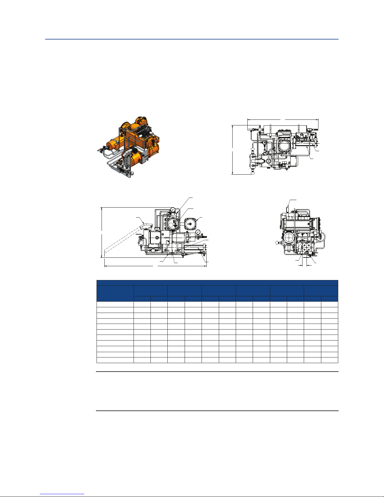
Installation and Operation Manual
Dimension
Double-Acting Actuator
Product Data Sheet EHO
March 2015
EHO.01.05.EN, Page 2 of 2, Rev. 0
Section 9: Weights and Dimensions
Part Number: VA001-507-32, Rev. 1
Section 9: Weights and Dimensions
9.1 EHO Standard Double Acting
August 2016
Actuator
G01001.5 39.8 1010.9 27.7 703.6 28.3 718.8 57.9 1470.7 2.4 61.0 513 233
G2002.0 40.6 1031.2 28.7 729.0 29.0 736.6 58.3 1480.8 2.9 73.7 546 248
G3004.0 46.8 1188.7 30.1 764.5 32.5 825.5 61.5 1562.1 3.5 88.9 626 284
G4003.0 52.0 1320.8 34.5 876.3 31.9 810.3 66.8 1696.7 4.3 109.2 770 349
G4004.0 53.0 1346.2 35.5 901.7 32.9 835.7 67.8 1722.1 5.3 134.6 783 355
G5004.0 58.3 1480.8 37.4 950.0 34.8 883.9 73.2 1859.3 5.5 139.7 1141 518
G5005.0 59.3 1506.2 38.4 975.4 35.8 909.3 74.2 1884.7 6.5 165.1 1300 590
G7005.0 64.3 1633.2 40.4 1026.2 39.7 1008.4 81.6 2072.6 6.8 172.7 1786 810
G7008.0 65.3 1658.6 41.4 1051.6 40.7 1033.8 82.6 2098.0 7.8 198.1 1829 830
G8008.0 76.5 1943.1 427.0 1085.8 39.5 1003.3 87.5 2222.5 8.0 203.2 2461 1116
G10008.0 93.6 2377.4 46.9 1191.3 43.6 1107.4 99.4 2524.8 10.5 266.7 3754 1703
ABCDE
INCH MM INCH MM INCH MM INCH MM INCH MM Lbs KG
OUTLINE DIMENSION AND DETAILS
Approximate
Weight
NOTE:
Weights and dimensions shown are nominal values, for accurate weights and
dimensions always refer to the General Arrangement Drawing for the unit being worked
on.
Weights and Dimensions
43
Page 47
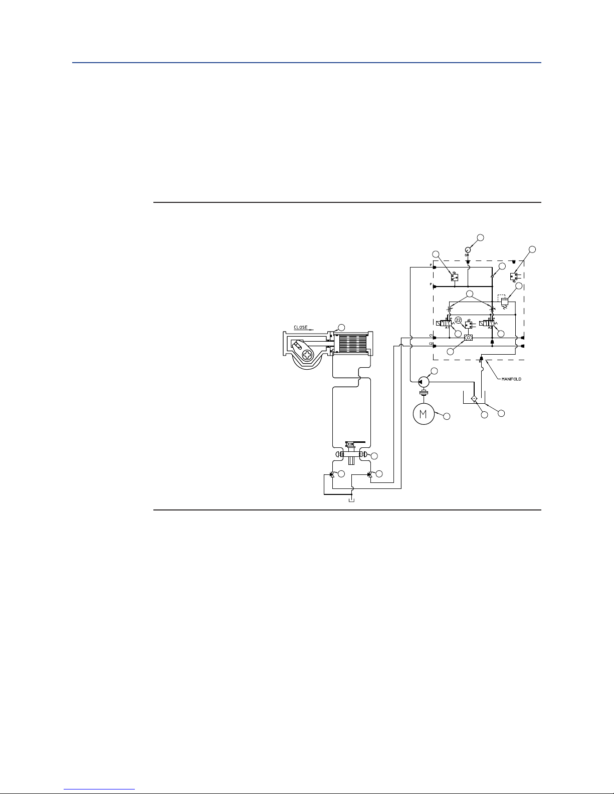
Section 10: Sample Wiring Diagram
(Q) Hydraulic Pressure Gauge
(R) Pressure Switch
(S) Pressure Transmitter(Optional)
(T) Check Valve
(U) Relief Valve
(V) Adjustable Flow Controls
(W) Bettis G-series Double Acting Actuator
(J) Opening Solenoid
(K) Closing Solenoid
(X) Shuttle Valve(Optional)
(Y) Hydraulic Pump
(Z) Electric Motor
(AA) Suc tion Strainer
(I) Fluid Reservoir
(L) Hand Pump
(M) Hand Pump Selection Valves
Q
August 2016
Installation and Operation Manual
Part Number: VA001-507-32, Rev. 1
Section 10: Sample Wiring Diagram
10.1 2-Way Electric Powered By an ElectroHydraulic Power Unit
Figure 26 2-Way Electric Powered By an Electro-Hydraulic Power Unit
W
M M
R
T
V
J
X
Y
Z
L
K
I
AA
S
U
44
Sample Wiring Diagram
Page 48

Installation and Operation Manual
(A) Pressure Gauge(Optional)
(B) Nitrogen Relief Valve(Optional)
(D) Isolation Valve(Optional)
(E) Hydraulic Accumulator With Nitrogen Blanket
Charge(Optional)
(H) Accumulator Isolation Valve(Optional)
(N) Accumulator Isolation Valve(Optional)
(R) Pressure Switch
(Q) Hydraulic Pressure Gauge
(S) Pressure Transmitter(Optional)
(T) Check Valve
(V) Adjustable Flow Controls
(U) Relief Valve
(O) Hand Pump Isolation Valve(Optional)
(W) Bettis G-series Double Acting Actuator
(AB) Pressure Transmitter(Optional)
(J) Opening Solenoid
(K) Closing Solenoid
(P) ESD Solenoid Valve(Optional)
(X) Shuttle Valve(Optional)
(AC) Shuttle Valve(Optional)
(Y) Hydraulic Pump
(AD) Accumulator override valve to open(Optional)
(AE) Accumulator override valve to close(Optional)
(Z) Electric Motor
(AA) Suction Strainer
(I) Fluid Reservoir
(L) Hand Pump
(M) Hand Pump Selection Valves
Part Number: VA001-507-32, Rev. 1
Section 10: Sample Wiring Diagram
August 2016
10.2 2-Way Electric With Emergency Shutdown
Feature Powered By an Electro-Hydraulic
Power Unit
Figure 27 2-Way Electric with Emergency Shutdown Feature Powered By an
Electro-Hydraulic Power Unit
A
B
E
H
D
Q
R
N
V
S
T
U
O
W
Y
AD AE
L
M M
J
X
Z
K
I
AA
P
AC
Sample Wiring Diagram
45
Page 49

Qualified service personnel are available upon request for problems, which our customers do not wish to
handle. If the requirement should arise please feel free to contact:
Emerson
Actuation Technologies, Inc.
19200 Northwest Freeway
Houston, TX 77065
T +1 281 477 4100
F +1 281 477 2809
Page 50

Page 51

World Area Configuration Centers (WACC) offer sales support,
service, inventory and commissioning to our global customers.
Choose the WACC or sales office nearest you:
NORTH & SOUTH AMERICA
19200 Northwest Freeway
Houston, TX 77065
T +1 281 477 4100
F +1 281 477 2809
Av. Hollingsworth,
325, Iporanga Sorocaba,
SP 18087-105
Brazil
T +55 15 3238 3788
F +55 15 3228 3300
ASIA PACIFIC
No. 9 Gul Road
#01-02 Singapore 629361
T +65 6777 8211
F +65 6268 0028
No.1 Lai Yuan Road
Wuqing Development Area
Tianjin 301700
P.R.China
T +86 22 8212 3300
F +86 22 8212 3308
For complete list of sales and manufacturing sites, please visit
www.emerson.com/actuationtechnologieslocations
or contact us at info.actuationtechnologies@emerson.com
MIDDLE EAST & AFRICA
P. O. Box 17033
Dubai
United Arab Emirates
T +971 4 811 8100
F +971 4 886 5465
P. O. Box 10305
Jubail 31961
Saudi Arabia
T +966 3 340 8650
F +966 3 340 8790
24 Angus Crescent
Longmeadow Business Estate
East P.O. Box 6908; Greenstone;
1616 Modderfontein, Extension 5
South Africa
T +27 11 451 3700
F +27 11 451 3800
EUROPE
Berenyi u. 72-100
Videoton Industry Park
Building #230
Székesfehérvár 8000
Hungary
T +36 22 53 09 50
F +36 22 54 37 00
www.emerson.com/bettis
©2016 Emerson. All rights reserved.
The Emerson logo is a trademark and service mark of Emerson
Electric Co. Bettis is a mark of the Emerson family of companies.
All other marks are property of their respective owners.
The contents of this publication are presented for information
purposes only, and while every effort has been made to ensure
their accuracy, they are not to be construed as warranties or
guarantees, express or implied, regarding the products or
services described herein or their use or applicability.
All sales are governed by our terms and conditions, which
are available on request. We reserve the right to modify or
improve the designs or specifications of our products at any
time without notice.
 Loading...