

Page 1

User Guide
FXMP25
Field Controller
Part Number: 0476-0009-03
Issue: 3
www.controltechniques.com
Page 2

General Information
The manufacturer accepts no liability for any consequences resulting from inappropriate, negligent or
incorrect installation or adjustment of the optional operating parameters of the equipment or from
mismatching the field controller with the motor.
The contents of this guide are believed to be correct at the time of printing. In the interests of a commitment
to a policy of continuous development and improvement, the manufacturer reserves the right to change the
specification of the product or its performance, or the contents of the guide, without notice.
All rights reserved. No parts of this guide may be reproduced or transmitted in any form or by any means,
electrical or mechanical including photocopying, recording or by an information storage or retrieval system,
without permission in writing from the publisher.
Field Controller software version
This product is supplied with the latest software version. If this drive is to be connected to an existing system
or machine, all drive software versions should be verified to confirm the same functionality as drives of the
same model already present. This may also apply to drives returned from a Control Techniques Service
Centre or Repair Centre. If there is any doubt please contact the supplier of the product. The software
versions of the drive can be checked by looking at Pr 97 and Pr 99.
When used in conjunction with a Mentor MP the Mentor MP software must be V01.05.01 or later.
Environmental statement
Control Techniques is committed to minimising the environmental impacts of its manufacturing operations
and of its products throughout their life cycle. To this end, we operate an Environmental Management
System (EMS) which is certified to the International Standard ISO 14001. Further information on the EMS,
our Environmental Policy and other relevant information is available on request, or can be found at
www.greendrives.com.
The electronic variable-speed drives manufactured by Control Techniques have the potential to save
energy and (through increased machine/process efficiency) reduce raw material consumption and scrap
throughout their long working lifetime. In typical applications, these positive environmental effects far
outweigh the negative impacts of product manufacture and end-of-life disposal.
Nevertheless, when the products eventually reach the end of their useful life, they must not be discarded
but should instead be recycled by a specialist recycler of electronic equipment. Recyclers will find the
products easy to dismantle into their major component parts for efficient recycling. Many parts snap
together and can be separated without the use of tools, while other parts are secured with conventional
fasteners. Virtually all parts of the product are suitable for recycling.
Product packaging is of good quality and can be re-used. Large products are packed in wooden crates,
while smaller products come in strong cardboard cartons which themselves have a high recycled fibre
content. If not re-used, these containers can be recycled. Polythene, used on the protective film and bags
for wrapping product, can be recycled in the same way. Control Techniques' packaging strategy prefers
easily-recyclable materials of low environmental impact, and regular reviews identify opportunities for
improvement.
When preparing to recycle or dispose of any product or packaging, please observe local legislation and
best practice.
REACH legislation
EC Regulation 1907/2006 on the Registration, Evaluation, Authorisation and restriction of Chemicals
(REACH) requires the supplier of an article to inform the recipient if it contains more than a specified
proportion of any substance which is considered by the European Chemicals Agency (ECHA) to be a
Substance of Very High Concern (SVHC) and is therefore listed by them as a candidate for compulsory
authorisation.
For current information on how this requirement applies in relation to specific Control Techniques products,
please approach your usual contact in the first instance. Control Techniques position statement can be
viewed at:
http://www.controltechniques.com/REACH
Copyright © October 2011 Control Techniques Ltd.
Issue Number: 3
Page 3

Contents
1 Safety information ...............................................................6
1.1 Warnings, cautions and notes .................................................................6
1.2 Electrical safety - general warning ..........................................................6
1.3 System design and safety of personnel ..................................................6
1.4 Environmental limits ................................................................................7
1.5 Access .....................................................................................................7
1.6 Fire protection .........................................................................................7
1.7 Compliance with regulations ...................................................................7
1.8 Motor .......................................................................................................7
1.9 Adjusting parameters ..............................................................................7
1.10 Electrical installation ................................................................................8
2 Product information ............................................................9
2.1 Ratings ....................................................................................................9
2.2 Nameplate description .............................................................................9
2.3 FXMP25 features and options ...............................................................10
3 Mechanical installation .....................................................11
3.1 Fire protection .......................................................................................11
3.2 Electrical terminals ................................................................................14
3.3 Routine maintenance ............................................................................14
information
information
installation
installation
Safety
Product
Mechanical
Electrical
Getting started Parameters Setting-up Technical data Diagnostics UL listing information
4 Electrical installation ........................................................15
4.1 Electrical connections ............................................................................16
4.2 Protective ground connections ..............................................................17
4.3 AC supply requirements ........................................................................17
4.4 Line reactors .......................................................................................... 17
4.5 Cable and fuse size ratings ...................................................................18
5 Getting started ...................................................................27
5.1 Keypad and display ...............................................................................27
5.2 Resetting the field controller ..................................................................28
5.3 Security .................................................................................................28
5.4 Setting the controller back to default values .......................................... 29
5.5 Saving parameters ................................................................................29
6 Parameters .........................................................................30
6.1 Full parameter descriptions ...................................................................31
FXMP25 User Guide 3
Issue Number: 3 www.controltechniques.com
Page 4

7 Setting-up ..........................................................................44
8 Technical data ...................................................................53
8.1 Ratings ..................................................................................................53
8.2 FXMP25 derating for extended ambient operation ................................ 53
8.3 Power dissipation ..................................................................................53
8.4 AC supply requirements ........................................................................54
8.5 Line reactors .......................................................................................... 54
8.6 Temperature and humidity ....................................................................55
8.7 Storage ..................................................................................................55
8.8 Altitude ..................................................................................................55
8.9 IP rating .................................................................................................55
8.10 Corrosive gasses ...................................................................................56
8.11 RoHS compliance ..................................................................................56
8.12 Vibration ................................................................................................56
8.13 Acoustic noise .......................................................................................57
8.14 Overall dimensions ................................................................................57
8.15 Weight ...................................................................................................57
8.16 Cable and fuse size ratings ...................................................................57
8.17 Electromagnetic compatibility (EMC) ....................................................58
9 Diagnostics ........................................................................60
10 UL listing information .......................................................64
10.1 Conditions of acceptability .....................................................................64
10.2 AC supply specification .........................................................................64
10.3 Maximum continuous current ................................................................ 64
4 FXMP25 User Guide
www.controltechniques.com Issue Number: 3
Page 5

Declaration of Conformity
Control Techniques Ltd, The Gro, Newtown, Powys UK. SY16 3BE
FXMP25 Field Controller
The field controller product listed above has been designed and manufactured in
accordance with the following European harmonized standards:
EN 61800-5-1:2007
EN 61800-3:2004
EN 61000-6-2:2005
EN 61000-6-4:2007
The corresponding international standards are:
IEC 61800-5-1:2007
IEC 61800-3:2004
IEC 61000-6-2:2005
IEC 61000-6-4:2006
These products comply with the Low Voltage Directive 2006/95/EC and the
Electromagnetic Compatibility (EMC) Directive 2004/108/EC.
Adjustable speed electrical power drive systems - safety
requirements - electrical, thermal and energy
Adjustable speed electrical power drive systems. EMC
product standard including specific test methods
Electromagnetic compatibility (EMC). Generic standards.
Immunity standard for industrial environments
Electromagnetic compatibility (EMC). Generic standards.
Emission standard for industrial environments
T. Alexander
VP Technology
Newtown
Date: 8th July 2010
This electronic field controller product is intended to be used with appropriate
motors, controllers, electrical protection components and other equipment to
form complete end products or systems. Compliance with safety and EMC
regulations depends upon installing and configuring drives correctly, including
using the specified input filters. The drives must be installed only by professional
assemblers who are familiar with requirements for safety and EMC. The
assembler is responsible for ensuring that the end product or system complies
with all the relevant laws in the country where it is to be used. Refer to the User
Guide. An EMC Data Sheet is also available giving detailed EMC information.
FXMP25 User Guide 5
Issue Number: 3 www.controltechniques.com
Page 6

1 Safety information
WARNING
CAUT ION
NOTE
1.1 Warnings, cautions and notes
A Warning contains information, which is essential for avoiding a safety hazard.
A Caution contains information, which is necessary for avoiding a risk of damage to
the product or other equipment.
A Note contains information which helps to ensure correct operation of the product.
1.2 Electrical safety - general warning
The voltages used in the field controller can cause severe electrical shock and/or burns,
and could be lethal. Extreme care is necessary at all times when working with or
adjacent to the field controller.
Specific warnings are given at the relevant places in this Guide.
1.3 System design and safety of personnel
The field controller is intended as a component for professional incorporation into
complete equipment or system. If installed incorrectly, the field controller may present a
safety hazard.
The field controller uses high voltages and currents, carries a high level of stored
electrical energy, and is used to control equipment which can cause injury.
System design, installation, commissioning / start-up and maintenance must be carried
out by personnel who have the necessary training and experience. They must read this
safety information and this guide carefully.
The electrical inputs of the field controller must not be relied upon to ensure
safety of personnel. They do not isolate dangerous voltages from the output of
the field controller. The supply must be disconnected by an approved electrical
isolation device before gaining access to the electrical connections.
The field controller is not intended to be used for safety-related functions.
Careful consideration must be given to the function of the field controller which might
result in a hazard, either through its intended behavior or through incorrect operation
due to a fault. In any application where a malfunction of the field controller or its control
system could lead to or allow damage, loss or injury, a risk analysis must be carried out,
and where necessary, further measures taken to reduce the risk - for example, an overspeed protection device in case of failure of the field control.
6 FXMP25 User Guide
www.controltechniques.com Issue Number: 3
Page 7

1.4 Environmental limits
Instructions within the supplied data regarding transport, storage, installation and the
use of the field controller must be complied with, including the specified environmental
limits. Field controllers must not be subjected to excessive physical force.
information
Safety
1.5 Access
Access must be restricted to authorized personnel only. Safety regulations which apply
at the place of use must be complied with.
1.6 Fire protection
The field controller enclosure is not classified as a fire enclosure. A separate fire
enclosure must be provided. For further information refer to section 3.1 Fire
protection on page 11.
1.7 Compliance with regulations
The installer is responsible for complying with all relevant regulations, such as national
wiring regulations, accident prevention regulations and electromagnetic compatibility
(EMC) regulations. Particular attention must be given to the cross-sectional areas of
conductors, the selection of fuses and other protection, and protective ground
connections.
The FXMP25 User Guide contains instructions for achieving compliance with specific
EMC standards.
Within the European Union, all machinery in which this product is used must comply
with the following directives:
2006/42/EC: Safety of machinery
2004/108/EC: Electromagnetic compatibility
information
installation
installation
Product
Mechanical
Electrical
Getting started Parameters Setting-up Technical data Diagnostics UL listing information
1.8 Motor
Ensure the motor is installed in accordance with the manufacturer's recommendations.
Ensure the motor shaft is not exposed.
Low speeds may cause the motor to overheat because the cooling fan becomes less
effective. The motor should be installed with a protection thermistor. If necessary, an
electric forced ventilation fan should be used.
The values of the motor parameters set in the field controller affect the protection of the
motor. The default values in the field controller should not be relied upon.
1.9 Adjusting parameters
Some parameters have a profound effect on the operation of the field controller. They
must not be altered without careful consideration of the impact on the controlled system.
Measures must be taken to prevent unwanted changes due to error or tampering.
FXMP25 User Guide 7
Issue Number: 3 www.controltechniques.com
Page 8

1.10 Electrical installation
1.10.1 Electric shock risk
The voltages present in the following locations can cause severe electric shock and may
be lethal:
• AC supply cables and connections
• Output cables and connections
• Many internal parts of the field controller
Unless otherwise indicated, control terminals are single insulated and must not be
touched.
1.10.2 Stored charge
The field controller contains capacitors that remain charged to a potentially lethal
voltage after the AC supply has been disconnected. If the field controller has been
energized, the AC supply must be isolated at least five minutes before work may
continue.
8 FXMP25 User Guide
www.controltechniques.com Issue Number: 3
Page 9

2 Product information
Field output
voltage / current
Line input voltage/
frequency/current
Customer and
date code
Approvals
Serial number
FX-
External Field
MP-
Mentor Platform
25-
Maximum field current (A)
Key to approvals
CE approval Europe
RoHS compliant Europe
UL approval Worldwide
C Tick approval Australia
2.1 Ratings
Safety information
Maximum continuous input current
The value of the maximum continuous input current is given to aid the selection of
cables and fuses. The value is stated for worst-case conditions.
Continuous AC
input current
A
26 25
Continuous DC
output current
A
2.2 Nameplate description
Figure 2-1 Typical FXMP25 rating label
information
Product
Mechanical
installation
installation
Electrical
Getting started Parameters Setting-up Technical data Diagnostics UL listing information
2.2.1 Output current
The continuous output current ratings given on the rating label are for maximum 40°C
(104 °F) and 1000 m altitude. Derating is required for higher ambient temperatures
>40 °C (104 °F) and higher altitude. For derating information, refer to Chapter
8 Technical data on page 53.
2.2.2 Input current
The input current given on the rating label is the typical input current.
FXMP25 User Guide 9
Issue Number: 3 www.controltechniques.com
Page 10
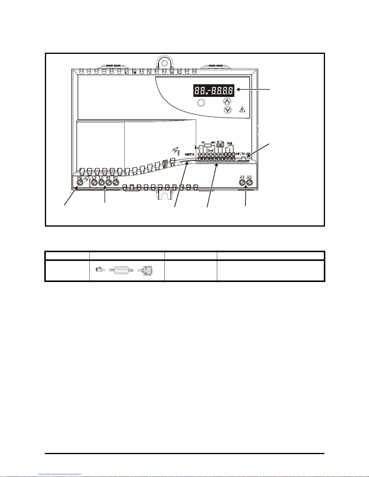
2.3 FXMP25 features and options
FXMP25
M
STORED CHARGE
10 min
Mode /Reset
Display
Mentor MP/
serial port connector
Armature voltage
feedback
connections
Control
terminals
Mentor II
connector
AC supply
and field output
connections
Ground
connection
Figure 2-2 FXMP25 features
2.3.1 Options available for FXMP25
Table 2-1 Options
Type Cable Name Further Details
Serial comms
lead
See also section 4.8 Serial communications on page 25 for information regarding serial
communications.
CT Comms cable
CT EIA (RS) -232 (4500-0087)
CT USB (4500-0096)
10 FXMP25 User Guide
www.controltechniques.com Issue Number: 3
Page 11

3 Mechanical installation
WARNING
WARNING
WARNING
WARNING
WARNING
Follow the instructions
Safety information
The mechanical and electrical installation instructions must be adhered to. Any
questions or doubt should be referred to the supplier of the equipment. It is the
responsibility of the owner or user to ensure that the installation of the field controller,
and the way in which it is operated and maintained, comply with the requirements of
the Health and Safety at Work Act in the United Kingdom or applicable legislation and
regulations and codes of practice in the country in which the equipment is used.
Competence of the installer
The field controller must be installed by professional assemblers who are familiar with
the requirements for safety and EMC. The assembler is responsible for ensuring that
the end product or system complies with all the relevant laws in the country where it is
to be used.
Enclosure
The field controller is intended to be mounted in an enclosure which prevents access
except by trained and authorized personnel, and which prevents the ingress of
contamination. It is designed for use in an environment classified as pollution degree 2
in accordance with IEC 60664-1. This means that only dry, non-conducting
contamination is acceptable.
information
installation
installation
Product
Mechanical
Electrical
Getting started Parameters Setting-up Technical data Diagnostics UL listing information
The equipment enclosure is rated at IP20 in accordance with IEC60529. It is designed
for installation within a protective enclosure which prevents unauthorized access
except for trained service personnel, and prevents contamination with conductive dust
and condensation.
The field controller enclosure is not classified as a fire enclosure. A separate fire
enclosure must be provided. For further information refer to section 3.1 below.
3.1 Fire protection
The field controller enclosure is not classified as a fire enclosure. A separate fire
enclosure must be provided.
For installation in the USA, a NEMA 12 enclosure is suitable.
For installation outside the USA, the following (based on IEC 62109-1, standard for PV
inverters) is recommended.
Enclosure can be metal and/or polymeric, polymer must meet requirements which can
be summarized for larger enclosures as using materials meeting at least UL 94 class
5VB at the point of minimum thickness.
Air filter assemblies to be at least class V-2.
FXMP25 User Guide 11
Issue Number: 3 www.controltechniques.com
Page 12
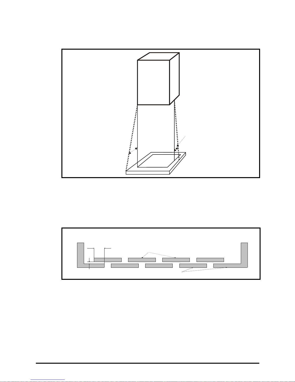
The location and size of the bottom shall cover the area shown in Figure 3-1. Any part of
Drive
5
o
5
o
Notless
th an 2X
Baffle plates (may be
above or below bottom
of enclosure)
X
Bottom of fire
enclosure
Not less
than 2
times ‘X’
Baffle plates (may be above or
below bottom of enclosure)
Bottom of fire enclosure
X
the side which is within the area traced out by the 5 ° angle is also considered to be part
of the bottom of the fire enclosure.
Figure 3-1 Fire enclosure bottom layout
The bottom, including the part of the side considered to be part of the bottom, must be
designed to prevent escape of burning material - either by having no openings or by
having a baffle construction. This means that openings for cables etc. must be sealed
with materials meeting the 5VB requirement, or else have a baffle above.
See Figure 3-2 for acceptable baffle construction. This does not apply for mounting in
an enclosed electrical operating area (restricted access) with concrete floor.
Figure 3-2 Fire enclosure baffle construction
12 FXMP25 User Guide
www.controltechniques.com Issue Number: 3
Page 13

Figure 3-3 Overall dimensions
176mm
(6.93in)
123.5mm (4.86in)
247mm (9.72in)
162mm
(6.38in)
168.5mm
(6.63in)
192.38
(7.57in)
90.27
(3.55in)
123.5mm (4.86in)
FXMP25
M
STORED CHARGE
10 min
Mode /Reset
information
installation
installation
Safety information
Product
Mechanical
Electrical
Getting started Parameters Setting-up Technical data Diagnostics UL listing information
Table 3-1 Back-plate information
Recommended
screw size
M6 1.5 N m (1.1 Ib ft) to 2.5 N m (1.8 Ib ft)
Torque range
FXMP25 User Guide 13
Issue Number: 3 www.controltechniques.com
Page 14
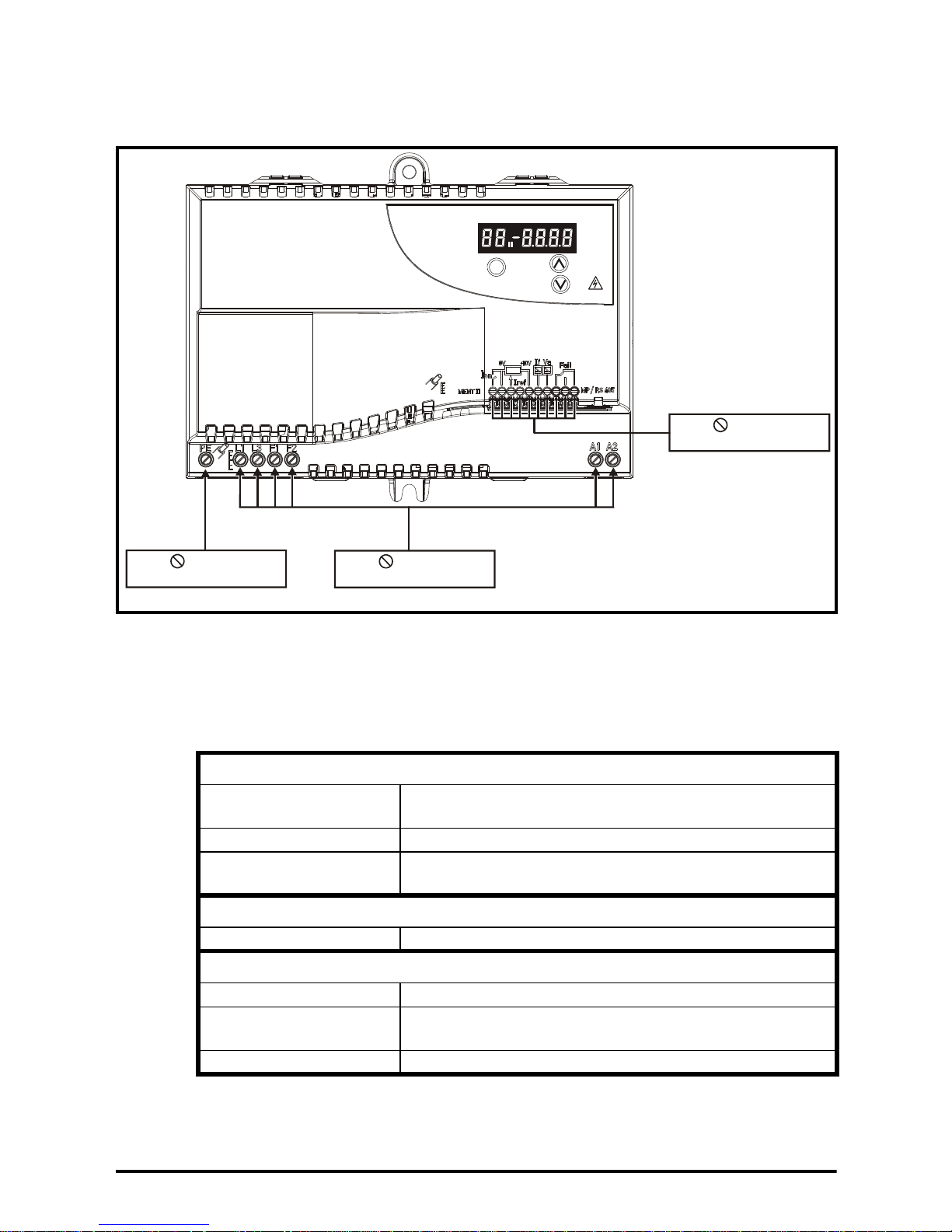
3.2 Electrical terminals
FXMP25
M
STORED CHARGE
10 min
Mode /Reset
4.5mm
Power connections
Torque: 0.6Nm (0.44 Ib ft)
3.5mm
Control connections
Torque: 0.4Nm (0.29 Ib ft)
4.5mm
Ground connection
Torque: 0.6Nm (0.44 Ib ft)
Figure 3-4 Location, terminal size and torque setting of power and protective
ground terminals
3.3 Routine maintenance
The FXMP25 should be installed in a cool, clean, well ventilated location. Contact with
moisture and dust should be prevented.
Regular checks of the following should be carried out to ensure the installation reliability
is maximized:
Environment
Ambient temperature
Dust Ensure the FXMP25 remains dust free
Moisture
Enclosure
Enclosure door filters Ensure filters are not blocked and that air is free to flow
Electrical
Screw connections Ensure all screw terminals remain tight
Crimp terminals
Cables Check all cables for signs of damage
Ensure the enclosure temperature remains at or below
maximum specified
Ensure the FXMP25 enclosure shows no signs of
condensation
Ensure all crimp terminals remains tight – check for any
discoloration which could indicate overheating
14 FXMP25 User Guide
www.controltechniques.com Issue Number: 3
Page 15

4 Electrical installation
WARNING
WARNING
WARNING
WARNING
WARNING
Electric shock risk
The voltages present in the following locations can cause severe electric shock and
may be lethal:
• AC supply cables and connections.
• DC cables, and connections.
• Many internal parts of the field controller.
• Control terminals are single insulated and must not be touched.
The voltages present in the FXMP25 controller are capable of inflicting a severe
electric shock and may be lethal. The Stop function of the Drive does not remove
dangerous voltages from the FXMP25 controller or the driven machine.
AC supplies to the FXMP25 controller must be disconnected at least 5 minutes before
any cover is removed or servicing work is performed.
Isolation device
The AC supply must be disconnected from the field controller using an approved
isolation device before any cover is removed from the field controller or before any
servicing work is performed.
Safety information
information
Product
Mechanical
installation
installation
Electrical
Getting started Parameters Setting-up Technical data Diagnostics UL listing information
The field controller is suitable for use on supplies of installation category III and lower,
according to IEC 60664-1. This means they may be connected permanently to the
supply at its origin in a building, but for outdoor installation additional over-voltage
suppression (transient voltage surge suppression) must be provided to reduce
category IV to category III.
ELV circuits are single insulated (basic insulation) only. Installer required to provide
supplementary insulation of accessible parts.
FXMP25 User Guide 15
Issue Number: 3 www.controltechniques.com
Page 16

4.1 Electrical connections
FXMP25
M
STORED CHARGE
10 min
Mode /Reset
PE L1 L3 F1 F2
L1 L3
A1 A2
Supply
branch
fuses
Isolator
Optional
EMC
filter
Fan supply
(where applicable)
Line
reactors
Armature
branch
fuses
Only required for
field weakening
applications in
stand alone mode
To armature controller
for field loss detection
in stand alone mode
NOTE
When operating in stand alone mode, a relay should be provided to indicate to the
controller that the unit has tripped and to protect against an overspeed condition.
Figure 4-1 FXMP25 power connections
If the voltage rating of the field is much lower than the supply voltage it is advisable to
use a transformer to reduce the supply voltage. This maximises the resolution of the
controller and prevents the possibility of excessive voltage being applied to the field
winding.
16 FXMP25 User Guide
www.controltechniques.com Issue Number: 3
Page 17

4.2 Protective ground connections
WARNING
NOTE
The field controller must be connected to the system protective ground of the AC supply.
The protective ground wiring must conform to local regulations and codes of practice.
See section 4.3.1 MOV protective ground disconnect on page 17 for possible
exceptions.
Ground loop impedance
The ground loop impedance must conform to the requirements of local safety
regulations.
The field controller must be connected by a protective ground connection capable of
carrying the prospective fault current until the protective device (fuse etc,) disconnects
the AC supply. The protective ground connections must be inspected and tested at
appropriate intervals.
4.3 AC supply requirements
For detailed information regarding AC supply requirements, please refer to section
8.4 AC supply requirements on page 54.
4.3.1 MOV protective ground disconnect
In some special circumstances, for example during a high potential test or in certain
situations with IT supplies and multiple generators there may be a requirement to
disconnect the MOV protective ground connection. If the MOV protective ground
connection is disconnected the immunity of the field controller to high voltage pulses is
reduced. It is then only suitable for use with supplies having overvoltage category II, i.e.
not for connection at the origin of the low voltage supply within a building. If the MOV to
protective ground connection is not required then do not make a protective ground
connection to the FXMP25.
Safety information
information
Product
Mechanical
installation
installation
Electrical
Getting started Parameters Setting-up Technical data Diagnostics UL listing information
4.4 Line reactors
The FXMP25, in common with all naturally commutated SCR drives, causes voltage
notches at the input supply terminals. To avoid disturbances with other equipment using
the same supply, the addition of external line inductance is strongly recommended in
order to restrict the depth of notches imposed. This is generally not necessary where a
dedicated transformer is used to supply the FXMP25.
The following recommendations for added line inductance, have been calculated based
on the power drive systems standard: EN 61800-3:2004 "Adjustable speed electrical
power drive systems - Part 3: EMC requirements and specific test methods".
Table 4-1 Minimum values of L
Field output
current
A μH μH A
25 230 290 26
On typical field windings or high inductance loads the output current is smooth DC and
therefore the rms input current is approximately equal to the DC output current.
The above assumes the supply has 1.5 % impedance and a minimum supply rating of
5 kA.
and inductor current rating for a typical application
add
System voltage Typical current
400 V 480 V
rating
FXMP25 User Guide 17
Issue Number: 3 www.controltechniques.com
Page 18

Control of current below 250 mA (thyristor holding currents) should be avoided. If
CAUT ION
WARNING
WARNING
WARNING
NOTE
control at this level is required then line reactors must be installed to reduce the effect
of dv/dt as thyristors turn off.
4.5 Cable and fuse size ratings
The selection of the correct fuse is essential to ensure the safety of the installation.
The AC supply inputs in the FXMP25 controller are fitted with auxiliary fuses for
protection against short circuits in the FXMP25 controller and field-winding of the
motor. These fuses will not protect the supply cables to the FXMP25 controller. There
are other fuses are suggested to install in branch circuits. The branch circuit fuses will
protect the supply cables to the FXMP25 controller. This section shows recommended
cable sizes and fuse ratings for a number of current levels. Failure to observe this
recommendation will cause a risk of fire.
Wiring must be in accordance with local regulations and codes of practice. The table
shows typical cable sizes for power input and output wiring. In the event of a conflict,
local regulations prevail.
Maximum continuous input currents are given in section 2.1 Ratings on page 9 to aid
the selection of fuses and cabling.
The cable sizing selected when installing the FXMP25 must comply with local wiring
regulations. The information provided in this section is for guidance purposes only.
The power terminals on the FXMP25 are designed to accommodate a maximum cable
size of 5.26 mm
2
(10 AWG).
The actual size depends on a number of factors including:
• Actual maximum continuous current
• Ambient temperature
• Cable support, method and grouping
• Cable voltage drop
Where continuous field current is reduced, the cable sizing selected can be appropriate
for the reduced current. The field controller parameters should be programmed with the
correct values.
When using reduced cable sizes, the branch circuit protection fuse rating needs to be
reduced in line with the cable size selected.
Table 4-2 gives examples of the cable sizes based on IEC 60364-5-52 and UL508C/
NEC. The example cable sizes below assume three current-carrying conductors per
cable or raceway and 40 °C ambient temperature.
18 FXMP25 User Guide
www.controltechniques.com Issue Number: 3
Page 19

Table 4-2 Typical cable sizes
NOTE
WARNING
IEC 60364-5-52
Input/Output
4 mm
2
1. Assumes the use of XLPE or EPR insulated cables in mounting method B2 as per
Table B52.5.
2. Assumes the use of 75 °C copper cable as per table 310.16 of the National
Electrical code.
4.5.1 Armature connections A1 A2
Connection to A1, A2 is only required in stand alone mode for voltage monitoring of the
armature voltage during field weakening. Armature branch fuses should be located
close to the armature supply and sized to protect the cable from the fuses to the
FXMP25. Cables 0.5 mm
2
to 5.26 mm2 (22 AWG to 10 AWG) should be used.
4.5.2 Fusing for FXMP25
Table 4-3 Ferraz Shawmut internal semiconductor fusing*
[1]
UL508C/National Electrical Code
10 AWG
[2]
Safety information
information
Product
Mechanical
installation
installation
Electrical
Fuse type
Rating
Vac
Rating
A
Catalog
number
Ref
number
10 x 38 mm ferrule 690 30 FR10GB69V30 M330015
*Internal semiconductor fusing is for protection of SCR / thyristor bridge only.
Table 4-4 Ferraz Shawmut supply branch circuit protection fusing
Fuse type
Rating
Vac
Rating
A
Catalog
number
Ref
number
UL Class J
alternative
14 x 51 mm ferrule 500 32 FR14GG50V32 W216656
Table 4-5 Cooper Bussman supply branch circuit protection fusing
Fuse type
Rating
Vac
Rating
A
Catalog number
10.3 x 38 mm ferrule 600 V 30 LP-CC-30
Table 4-6 Siba supply branch circuit protection fusing
Fuse type
Rating
Vac
Rating
A
Catalog number
NH 000 knife blade 690 V 32 20 477 13.32
Recommended fuses are based on rated current operation. Supply branch circuit
protection is required for cable and internal control electronics protection.
Getting started Parameters Setting-up Technical data Diagnostics UL listing information
4.5.3 Internal semiconductor fuses
The internal semiconductor fuses provide protection to the FXMP25 SCR / thyristor
bridge only. The fuses can rupture if there is a fault in the field circuit. The user should
check the internal semiconductor fuses if the FXMP25 is tripping field loss (FdL) while
enabled.
Electric shock risk
If the FXMP25 controller has been energized, the supply must be isolated for at least
five minutes. This allows the internal capacitors to discharge fully before work may
commence.
FXMP25 User Guide 19
Issue Number: 3 www.controltechniques.com
Page 20

Isolate the power before removing the internal semiconductor fuses.
WARNING
1
2
3
4
Figure 4-2 Removing the internal semiconductor fuses
1. Remove mounting screws (M6 recommended).
2. Apply pressure at the two points shown on the bottom of the FXMP25 to release the
terminal cover clips.
3. Open the terminal cover in the direction shown.
4. Remove the internal semiconductor fuses.
20 FXMP25 User Guide
www.controltechniques.com Issue Number: 3
Page 21

4.6 EMC (Electromagnetic compatibility)
NOTE
CAUT ION
WARNING
CAUT ION
The FXMP25 meets immunity requirements (specified in section 8.17 Electromagnetic
compatibility (EMC) on page 58) with no special precautions.
Some special measures may be required in certain applications where the control
cables are long or pass outside the building. See section 4.6.1 Surge immunity of
control circuits - long cables and connections outside a building on page 22.
Radio frequency noise emission can occur from any of the power connections i.e. AC
supply and field output terminals.
For many applications in heavy industrial environments the noise emission is not
sufficient to cause interference to other equipment.
When radio frequency emission must be limited an input EMC filter can be installed.
Shielded cables must be used for the field and the shield must be clamped to grounded
metallic parts at both ends. The standard is met for cable lengths up to 100m.
Safety information
information
Product
Mechanical
installation
Table 4-7 FXMP25 emission compliance
Filter * Conformity
No filter C4
Schaffner FN3280H-25-33 C2
* Filters can be sourced directly from Schaffner.
Key (shown in decreasing order of permitted emission level):
C4 EN 61800-3:2004 second environment, restricted distribution (Additional
measures may be required to prevent interference).
C2 Industrial generic standard EN 61000-6-4:2007.
EN 61800-3:2004 first environment restricted distribution (The following caution
is required by EN 61800-3:2004).
The recommended filter has been selected to be compatible with the SCR control
circuit in the FXMP25 unit. It is strongly recommended that no other filter type be used.
SCRs can be damaged by filters with unsuitable output impedance (capacitors
connected directly to the output).
The filter must be used in conjunction with a suitable RFI filter for the armature supply.
The filter input must obtain its supply from the input of the armature filter and line
chokes, otherwise it may be over-heated and possibly damaged by the armature
voltage notching.
installation
Electrical
Getting started Parameters Setting-up Technical data Diagnostics UL listing information
This is a product of the restricted distribution class according to IEC 61800-3. In a
residential environment this product may cause radio interference in which case the
user may be required to take adequate measures.
FXMP25 User Guide 21
Issue Number: 3 www.controltechniques.com
Page 22

EN 61800-3:2004 defines the following:
Signal from plant Signal to drive
0V 0V
30V zener diode
e.g. 2xBZW50-15
• The first environment is one that includes residential premises. It also includes
establishments directly connected without intermediate transformers to a lowvoltage power supply network which supplies buildings used for residential
purposes.
• The second environment is one that includes all establishments other than those
directly connected to a low-voltage power supply network which supplies buildings
used for residential purposes.
• Restricted distribution is defined as a mode of sales distribution in which the
manufacturer restricts the supply of equipment to suppliers, customers or users who
separately or jointly have technical competence in the EMC requirements of the
application of drives.
4.6.1 Surge immunity of control circuits - long cables and connections outside
a building
The input/output ports for the control circuits are designed for general use within
machines and small systems without any special precautions.
In applications where they may be exposed to high-energy voltage surges, some
special measures may be required to prevent malfunction or damage. Surges may be
caused by lightning or severe power faults in association with grounding arrangements
which permit high transient voltages between nominally grounded points. This is a
particular risk where the circuits extend outside the protection of a building.
As a general rule, if the circuits are to pass outside the building where the drive is
located, or if cable runs within a building exceed 30 m, some additional precautions are
advisable. One of the following techniques should be used:
1. Galvanic isolation, i.e. do not connect the control 0 V terminal to ground. Avoid loops in
the control wiring, i.e. ensure every control wire is accompanied by its return (0 V) wire.
2. Shielded cable with additional power ground bonding. The cable shield may be
connected to ground at both ends, but in addition the ground conductors at both
ends of the cable must be bonded together by a power ground cable (equipotential
bonding cable) with cross-sectional area of at least 10 mm
2
, or 10 times the area of
the signal cable shield, or to suit the electrical safety requirements of the plant. This
ensures that fault or surge current passes mainly through the ground cable and not
in the signal cable shield. If the building or plant has a well-designed common
bonded network this precaution is not necessary.
3. Additional over-voltage suppression - for the analog and digital inputs and outputs, a
zener diode network or a commercially available surge suppressor may be
connected in parallel with the input circuit as shown in Figure 4-3 and Figure 4-4.
Figure 4-3 Surge suppression for digital and unipolar inputs and outputs
22 FXMP25 User Guide
www.controltechniques.com Issue Number: 3
Page 23

Figure 4-4 Surge suppression for analog and bipolar inputs and outputs
Signal from plant Signal to drive
0 V 0 V
2 x 15 V zener diode
e.g. 2xBZW50-15
Iref
+10V
If
Va
Fail
11 1
2
3
45
6
7
8
910
0V
Ion
Surge suppression devices are available as rail-mounting modules, e.g. from Phoenix Contact:
Unipolar TT-UKK5-D/24 DC
Bipolar TT-UKK5-D/24 AC
Safety information
information
Product
Mechanical
installation
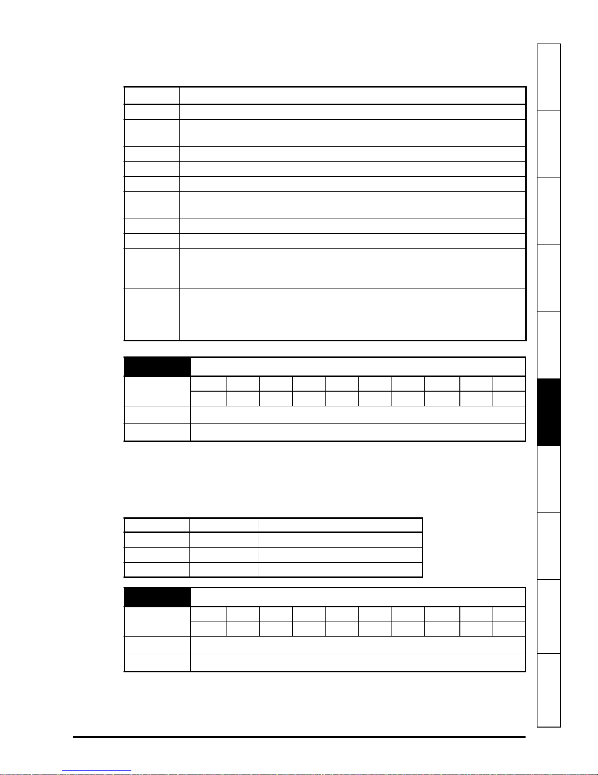
4.7 Control terminal specification
Figure 4-5 Control terminals
1 (Ion) Digital input
Dual Function
Type
Voltage range 0 V to 24 V
Absolute maximum applied
voltage range
Load 2.4 mA at 0 V (sink)
Input threshold High: 11 V, Low: 9 V
Update rate 4 ms
Field economy select or enable
controller (See Pr 81)
Single ended, negative logic (0 V
common for normal operation)
-18 V to 30 V
installation
Electrical
Getting started Parameters Setting-up Technical data Diagnostics UL listing information
2 (0V) 0V common
Function
3 (Iref) Analog input
Function Current demand input
Full scale voltage range 0 to 10 V
Absolute maximum voltage range -18 V to 30 V
Input resistance
Resolution 10 bits
Sample period 4 ms
FXMP25 User Guide 23
Issue Number: 3 www.controltechniques.com
Common connection for all external
devices
44 kΩ
Page 24

4 Not used
WARNING
5 (+10V) 10V user output
Function Supply for Analog input terminal
Voltage tolerance 2 %
Rated output current 5 mA
Over 5 mA, the current is limited, but
Protection
6 (If) Field current output signal
7 (Va) Armature voltage output signal
Type Single-ended voltage
Voltage range 0 to 10 V
Maximum output current 5 mA
Load resistance 2 kΩ min
Protection 5 mA short circuit protection
Resolution 10 bits
Update period 4 ms
there is no trip (Voltage is less than 10 V
if the current is higher than 5 mA)
8 Fail relay common
9 Fail relay normally open
10 Fail relay normally closed
Function
Type Fo rm C
Rating
Contact condition
Update period 4 ms
FXMP25 OK indicator (See Pr 01 and
Pr 27.
250/125 Vac category 1/2
5 A nominal resistive load
5 A 30 Vdc
Energized when power applied and
FXMP25 OK
Status relay contact is over-voltage category II.
24 FXMP25 User Guide
www.controltechniques.com Issue Number: 3
Page 25

4.8 Serial communications
1
8
4.8.1 Introduction
The FXMP25 has a standard 2-wire EIA485 interface (serial communications interface)
which enables all drive set-up, operation and monitoring to be carried out with a PC or
controller if required. Therefore it is possible to control the drive entirely by serial
communications without the need for a keypad or other control cabling.
The drive supports Modbus RTU configured as the default protocol, which is used with
the PC-tools commissioning/start-up software as provided on the CD ROM with the
product.
Safety information
information
Product
The serial communications port of the drive is a RJ45 socket, which is isolated from the
power stage.
The communications port applies a 2 unit load to the communications network.
4.8.2 Serial communications connections
The FXMP25 has a serial communications port (serial port) as standard supporting two
wire EIA(RS)-485 communications. See Table 4-8 for the connection details for the
RJ45 connector.
Figure 4-6 Serial communications port
Table 4-8 RJ45 connections
Pin Function
1
2
3
4
5
6
7
8
Shell
120 Ω Termination resistor
RX TX
0 V isolated
+24 V (100 mA)
0V isolated
TX enable
RX\ TX\
RX\ TX\ (if termination resistors are required, jumper (link) to pin 1)
0 V isolated
Mechanical
installation
installation
Electrical
Getting started Parameters Setting-up Technical data Diagnostics UL listing information
The communications port applies a two-unit load to the communications network.
Connectors 2, 3, 7 and shield must always be made to the serial communications port.
Shielded cable must be used at all times.
USB/EIA232 to EIA485 Communications
An external USB/EIA232 hardware interface such as a PC cannot be used directly with
the 2-wire EIA485 interface of the drive. Therefore a suitable converter is required.
FXMP25 User Guide 25
Issue Number: 3 www.controltechniques.com
Page 26

Suitable USB to EIA485 and EIA232 to EIA485 isolated converters are available from
NOTE
Control Techniques as follows:
• CT USB Comms cable (CT Part No. 4500-0096)
• CT EIA232 Comms cable (CT Part No. 4500-0087)
When using one of the above converters or any other suitable converter with the
FXMP25, it is recommended that no terminating resistors be connected on the network.
It may be necessary to 'link out' the terminating resistor within the converter depending
on which type is used. The information on how to link out the terminating resistor will
normally be contained in the user information supplied with the converter.
4.8.3 Serial communications set-up parameters
The following parameters need to be set according to the system requirements.
This parameter defines the communications protocol used by the 485 comms port on
the drive. This parameter can be changed via the drive keypad, via a Solutions Module
or via the comms interface itself. If it is changed via the comms interface, the response
to the command uses the original protocol. The master should wait at least 20 ms
before sending a new message using the new protocol. (Note: ANSI uses 7 data bits, 1
stop bit and even parity; Modbus RTU uses 8 data bits, 2 stops bits and no parity).
When using the CT EIA232 Comms cable the available baud rate is limited to
19.2 k baud.
Parameters Pr 95 and Pr 96 select the address and baud rate respectively as detailed in
section 6 Parameters on page 30.
26 FXMP25 User Guide
www.controltechniques.com Issue Number: 3
Page 27

5 Getting started
M
STORED CHARGE
10 min
Mode /Reset
FXMP25
Status mode
Parameter view mode
Parameter edit mode
M
STORED CHARGE
10 min
Mode /Reset
FXMP25
M
STORED CHARGE
10 min
Mode /Reset
FXMP25
Status
Parameter
value
Parameter
number
(flashes)
Parameter
value
Parameter
number
Parameter
value (flashes)
M
STATUS MODE
or
PARAMETER VIEW MODE
Select parameter to view
orPress
Parameter number flashing
PARAMETER EDIT MODE
Change parameter value
orPress
Parameter value flashing
M
Press and
release
M
Hold
for 2s
4 mins
timeout
Press and
release
Press and
release
Press and
release
M M
M
5.1 Keypad and display
The display will show different information depending on the display mode selected.
There are three display modes as shown below.
Figure 5-1 Display modes
Figure 5-2 Selecting and changing parameters
information
installation
installation
Safety information
Product
Mechanical
Electrical
Getting started
When in status mode pressing and releasing the MODE key will change the display
from status mode to parameter view mode.
In parameter view mode, the left hand display flashes the parameter number and the
right hand display shows the value of that parameter. The left hand display flashing
indicates that the up and down keys will select a different parameter to be
viewed. Holding the up key will cause the parameter number to increment to Pr 99.
Parameters Setting-up Technical data Diagnostics UL listing information
FXMP25 User Guide 27
Issue Number: 3 www.controltechniques.com
Page 28

A single up key action when the last parameter is being displayed will cause the
M
MMM
M
M
M
parameter number to roll over to the lowest parameter available in the current mode.
Similarly holding the down key will cause the parameter number to decrement until
the lowest parameter available is reached and a single down key action will cause
the parameter number to roll under to Pr 99. Pressing and releasing the Mode key
again will change the display from parameter view mode to parameter edit mode.
In parameter edit mode, the right hand display flashes the value in the parameter being
shown in the left hand display.
Pressing the MODE key in parameter edit mode will return the controller to
parameter view mode. If the MODE key is pressed again then the controller will
return to status mode, but if either of the up or down keys are pressed to change
the parameter being viewed before the MODE key is pressed, pressing the
MODE key will change the display to parameter edit mode again. This allows the user to
easily change between parameter view and edit mode while setting up the field
controller.
Pressing the up and down keys simultaneously when editing a parameter will set
the value to zero immediately.
If no action is made while in parameter view or edit mode for 4 minutes the status mode
is entered automatically.
5.2 Resetting the field controller
The controller can be reset using the keypad by pressing the mode key for at least
two seconds in status or parameter view mode.
A reset is required in response to the following conditions:
• To reset the controller from a tripped state
• To implement a change in the value of certain parameters
5.3 Security
In the field controller’s default state no security is implemented, and any R/W parameter
can be adjusted. If Pr 98 (user security code) is set to any value other than 0, then the
value programmed will be taken as a security code. With a security code programmed,
on power up, no R/W parameter can be altered. It will not be possible to change any
parameter without first entering the security code. If Pr 98 is selected for viewing when a
security code has been programmed the value indicated will be 0 (to prevent the code
programmed from being read).
When a security code has been programmed, any attempt to enter edit mode will cause
the field controller to flash 'CodE' on the 4 digit display to prompt the user for a security
code (providing the parameter is R/W and not R/O). When the Up or Down keys
are pressed, the 4 digit display will then show the code being adjusted and the 2 digit
display will indicate 'Co'. On setting the code, the user presses the MODE key. If the
correct code has been entered then the field controller will switch to parameter edit
mode on the parameter the user had selected to edit, but if the correct code has not
been entered the field controller will return to parameter view mode.
28 FXMP25 User Guide
www.controltechniques.com Issue Number: 3
Page 29

5.4 Setting the controller back to default values
NOTE
M
M
NOTE
If Pr 00 is set to a non-zero value and edit mode is exited, the field controller is reset
when the field controller is inactive (Pr 77= OFF), the selected default parameters will
automatically be loaded. After the parameters have been set to default values, they are
automatically saved to the field controller’s EEPROM on power down. New values will
take effect on subsequent power up.
Table 5-1 Pr 00 settings
Value Display Function
0 nonE No action
1 Eur Load European defaults
2 USA Load USA defaults
If loading default when the drive is active, the display will flash FAIL once and then
Pr 00 will be change back to nonE.
Table 5-2 Status modes
Left hand
display
Status Explanation
Field controller
inhibited
Field controller has
tripped
The field controller is inhibited because the field controller
is disabled (Pr 77 = OFF).
The field controller has tripped. The trip code will be
displayed in the ‘right hand’ display
(see Chapter 9 Diagnostics on page 60).
The field controller is in a run state.
Field controller is
running
Pr 78 = Mode Selected an
Pr 77=On Standalone Mode or
Mentor MP Pr 5.77=On in MP Mode or
Mentor II ribbon cable is connected in Mentor II mode.
information
installation
installation
Safety information
Product
Mechanical
Electrical
Getting started
Parameters Setting-up Technical data Diagnostics UL listing information
To set defaults from MP or MII Mode, set Pr 78 = OFF then press to exit edit mode.
A power cycle is then required to gain access to Pr 00.
5.5 Saving parameters
Parameters are automatically saved when the MODE key is pressed when going
from parameter edit mode to parameter view mode.
A parameter change is not saved if a drive trip occurs when the parameter is changed.
FXMP25 User Guide 29
Issue Number: 3 www.controltechniques.com
Page 30

6 Parameters
All parameters are available in default Pr 78 = OFF (0)
In the table below the abreviations used in the table have the following meaning:
MP - In Mentor MP mode the field controller is being controlled by Mentor MP.
MII - In Mentor II mode the field controller is being controlled by Mentor II.
ST - In Stand alone mode the field controller is controlled by itself.
Table 6-1 Quick look-up parameter table
Pr Description MP MII ST Pr Description MP MII ST
00 Loading defaults
01 FXMP25 OK
02 Armature voltage
03 Flux reference
04 Flux reference input offset
05 Flux reference scaling
06
Armature voltage output scaling
07 Field flux output scaling
11
Field current feedback scaling
12 Autotune
25 FXMP25 OK flux level 9
26 FXMP25 OK hysteresis level 9
27 Flux threshold level exceeded 9
29 Motor saturation breakpoint 1
30 Motor saturation breakpoint 2
54 Flux feedback
55 Flux / voltage demand
56 Field current feedback
57 Percentage voltage demand
58 Field firing angle
Field weakening voltage set
59
point
60 Field output voltage
62 Field weakening loop P gain
63 Field weakening loop I gain
64 External flux reference select
9
9
9
9
9 75 Field voltage mode select 9
9
9
9
9
9
9
9
9
9
9
9
9
9
9
9
9
9
9
9
9
9
9
9
9
9
9
9
9
67 Field economy level 9
68 Maximum flux / voltage limit 9
69 Minimum flux / voltage limit 9
70 Rated field current 9
71 Flux loop P gain 9
72 Flux loop I gain 9
73 Rated field voltage 9
Rated field compensation
74
factor
76 AC supply 99
77 Enable field control 9
78 Field mode 999
80 Economy level selected 9
81 Digital input control
90 Trip 0 999
91 Trip 1 999
92 Trip 2 999
93 Trip 3 999
Parameter displayed at power
94
up
95 Serial address 9
96 Baud rate 9
97 Software version 999
98 User security code 999
99 Power software version 999
9
9
9
Parameter numbers are numbered so they match Mentor MP menu 5 parameters.
For example Pr 77 FXMP=Pr 5.77 on Mentor MP
30 FXMP25 User Guide
www.controltechniques.com Issue Number: 3
Page 31
6.1 Full parameter descriptions
Table 6-2 Key to parameter coding
Coding Attribute
Bit 1 bit parameter
FI
Txt Text: the parameter uses text strings instead of numbers.
VM Variable maximum: the maximum of this parameter can vary.
DP Decimal place: indicates the number of decimal places used by this parameter.
ND
US User save: saved in drive EEPROM when the user initiates a parameter save.
RW Read/write: can be written by the user.
BU
PS
Filtered: some parameters which can have rapidly changing values are filtered
when displayed on the drive keypad for easy viewing.
No default: when defaults are loaded (except when the drive is manufactured
or on EEPROM failure) this parameter is not modified.
Bit default one/unsigned: Bit parameters with this flag set to one have a default
of one (all other bit parameters have a default of zero. Non-bit parameters are
unipolar if this flag is one.
Power-down save: parameter automatically saved in drive
EEPROM when the under volts (UV) trip occurs.
Power-down save parameters are also saved in the drive when the user
initiates a parameter save.
information
installation
installation
Safety information
Product
Mechanical
Electrical
Getting started
00 Loading defaults
Coding
Bit FI Txt VM DP ND US RW BU PS
111
Range nonE(0), Eur(1), USA(2)
Update rate Actioned on exit of edit mode or FXMP25 reset
If this parameter is set to a non-zero value and edit mode is exited or the FXMP25 is
reset when the FXMP25 is inactive, the selected default parameters will automatically
be loaded. After the parameters have been set to default values they are automatically
saved to the FXMP25's internal EEPROM on power down. New values will take effect
on subsequent power up.
Value Display Function
0 nonE No action
1 Eur Load European defaults
2 USA Load USA defaults
01 FXMP25 OK
Coding
Bit FI Txt VM DP ND US RW BU PS
11
Range OFF (0) or On (1)
Parameters
Setting-up Technical data Diagnostics UL listing information
Update rate Background
Indicates the FXMP25 is not in the trip state.
FXMP25 User Guide 31
Issue Number: 3 www.controltechniques.com
Page 32

02 Armature voltage
Coding
Range 0 to 860 V
Update rate Background write
Bit FI Txt VM DP ND US RW BU PS
111
The average measured DC input voltage seen across the field controller A1 and A2
terminals.
03 Flux reference
Coding
Range 0.0 to 100.0 %
Update rate Background
Bit FI Txt VM DP ND US RW BU PS
111 1
This parameter displays the level of the analog signal present at the flux reference input,
this is a unipolar voltage input where the input range is 0 V to +10 V.
04 Flux reference input offset
Coding
Range ±100 %
Bit FI Txt VM DP ND US RW BU PS
111
Default 0.0
Update rate Background read
An offset can be added to flux reference input with a range from -100.0 % to 100.0 %. If
the sum of the input and the offset is outside the range 0 to 100 % the result will be
clamped at 0 or 100 %.
05 Flux reference scaling
Coding
Range 0.000 to 4.000
Default 1.000
Update rate Background
Bit FI Txt VM DP ND US RW BU PS
3111
The flux reference input is connected to the field economy parameter when the flux
input is selected. The maximum value of the field economy is 100 % and so the default
for the scaling parameter is 1 so that the demand is 100 % for 10 V input.
06 Armature voltage output scaling
Coding
Range 0.000 to 4.000
Bit FI Txt VM DP ND US RW BU PS
3111
Default 1.000
Update rate Background
The maximum value of Pr 02 is 860 which without any scaling will be converted to 10 V.
This parameter should be adjusted by the user for other full scale voltages.
32 FXMP25 User Guide
www.controltechniques.com Issue Number: 3
Page 33

07 Field flux output scaling
NOTE
Coding
Bit FI Txt VM DP ND US RW BU PS
Range 0.000 to 4.000
Safety information
3111
Default 1.500
Update rate Background
The default value of 1.500 will produce 10 V output on the analog output (terminal 6)
when the feedback is at 100 % (Pr 54 Flux Feedback).
11 Field current feedback scaling
Coding
Bit FI Txt VM DP ND US RW BU PS
111
Range 0 to 20
Default 10
Update rate Background
This parameter must be set to the same value as Pr 6.11 on Mentor II when used with
Mentor II. It defines the full scale current in amps.
This parameter must be set before Pr 78 is selected for Mentor II mode. If already in
Mentor II mode [Pr 78 = 2.H (2) or 2.F (3)] a power cycle is required before the new
values will take effect.
12 Autotune
Coding
Bit FI Txt VM DP ND US RW BU PS
11
Range OFF (0) or On (1)
information
installation
installation
Product
Mechanical
Electrical
Getting started
Parameters
Default OFF (0)
Update rate Background read
In stand alone mode, setting this parameter will instruct the field controller to set-up its
flux loop gains automatically. If any voltage is detected on the armature voltage input
during the autotune then the unit will trip.
At the end of the autotune routine, Pr 77 is set to 0 (off) when Pr 81 = 0. If Pr 81 = 1,
then the controller remains in the enabled condition as controlled by the digital input.
25 FXMP25 OK flux level
Coding
Bit FI Txt VM DP ND US RW BU PS
1111
Range 0.0 to 100.0 %
Default 6.7 %
Update rate 16 ms
This parameter sets the level at which field loss is detected and operates the fail relay in
Mentor II and standalone mode 100 % level = 150 % flux. 10 % flux / 1.5 = 6.7 the same
level as FXM5.
Setting-up Technical data Diagnostics UL listing information
FXMP25 User Guide 33
Issue Number: 3 www.controltechniques.com
Page 34

26 FXMP25 OK hysteresis level
Coding
Range 0.0 to 25.0 %
Default 0.0 %
Update rate 16 ms
Bit FI Txt VM DP ND US RW BU PS
1111
Set the hysteresis from the level set in Pr 25 to eliminate relay bounce when the level is
reached. If the value is greater or equal to the threshold Pr 25 plus half the hysteresis
band Pr 26 the output becomes active, or if the value is less than the threshold minus
half the hysteresis the output becomes inactive.
27 Flux threshold level exceeded
Coding
Range OFF (0) or On (1)
Update rate 16 ms
Bit FI Txt VM DP ND US RW BU PS
11
When set to On (1) indicates the value of flux is above threshold levels set by Pr 25 and
Pr 26.
29 Motor saturation breakpoint 1
Coding
Range 0 to 100 % of rated flux
Bit FI Txt VM DP ND US RW BU PS
111
Default 50
Update rate Background read
See Pr 30 for description.
30 Motor saturation breakpoint 2
Coding
Range 0 to 100 % of rated flux
Default 75
Update rate Background read
Bit FI Txt VM DP ND US RW BU PS
111
When the motor is operating in the field weakening voltage loop region the relationship
between the field current and the level of flux can be non linear. The field controller can
include the effects of this non linearity by representing the field current to flux
characteristic as a series of three lines as shown in the figure overleaf.
34 FXMP25 User Guide
www.controltechniques.com Issue Number: 3
Page 35

Safety information
Field
current (%)
flux (%)
50 75 100
100%
Pr
5.30
Pr
5.29
Linear characteristic
(i.e. no saturation)
information
Product
Mechanical
installation
If Pr 29 and Pr 30 have their default values of 50 and 75, the characteristic becomes
one line and there will be a linear relationship between the field controller estimate of
flux and the field current. If Pr 29 and Pr 30 are increased above 50 and 75 the field
controller estimate of flux can included the effect of the non linearity. It is unlikely that
information will be available to set-up these parameters, and so the values are
determined during the rotating autotune test (in Mentor MP mode only). To set these
values in stand alone mode use the following procedure:
• Ensure that Pr 29, Pr 30, Pr 68 and Pr 74 are set to their default values of 50 %,
75 %, 100 % and 100 % respectively.
• Set the speed demand to 1/4 of Base speed and run the machine up to speed and
check the speed of the machine using a hand held device.
• If the machine speed is lower than 1/4 of Base speed (which is normally the case)
adjust the Field compensation factor (Pr 74) down until the correct machine speed
is reached. If the machine speed is higher than
1
/
of Base speed (only possible if
4
the motor nameplate field current is low), adjust the Rated field current (Pr 70) up
until the correct machine speed is reached.
•Set Pr 68 Maximum flux to 75 % and measure the actual speed of the machine
(speed 75)
•Set Pr 68 Maximum flux to 50 % and measure the actual speed of the machine
(speed 50).
• Stop the machine and set Pr 68 Maximum flux back to 100 %.
•Set Pr 29 Motor saturation breakpoint 1 = 50 x set speed / actual speed (Speed 50)
•Set Pr 30 Motor saturation breakpoint 2 = 75 x set speed / actual speed (speed 75).
• Press mode to save parameters.
installation
Electrical
Getting started
Parameters
Setting-up Technical data Diagnostics UL listing information
FXMP25 User Guide 35
Issue Number: 3 www.controltechniques.com
Page 36

54 Flux feedback
Coding
Range ±150.0 %
Update rate Background write
Bit FI Txt VM DP ND US RW BU PS
111
Flux feedback after the current to flux converter, see motor saturation breakpoints in
Table 6-1 Quick look-up parameter table on page 30.
55 Flux / voltage demand
Coding
Range ±120.0 %
Update rate Mains period / 6 ms
Bit FI Txt VM DP ND US RW BU PS
111
When in current mode the flux demand from the field weakening voltage loop, subject to
the limits of Pr 68 and Pr 69. When in voltage mode [Pr 75 = On (1)] the voltage demand
is subject to the limits of Pr 68 and Pr 69.
56 Field current feedback
Coding
Range ±25.00 A
Bit FI Txt VM DP ND US RW BU PS
121
Update rate Background write
The current feedback in amps.
57 Percentage voltage demand
Coding
Range
Update rate Background write
Bit FI Txt VM DP ND US RW BU PS
111
±150.0 % (0 to150 % in half control mode)
Indicates percentage voltage demand. Negative value in full control indicates energy
absorption to force field down quicker.
58 Field firing angle
Coding
Range
Update rate Background write
Bit FI Txt VM DP ND US RW BU PS
111
0.0 to 180.0
°
0 ° = fully phased forward full volts applied to the field.
36 FXMP25 User Guide
www.controltechniques.com Issue Number: 3
Page 37

59 Field weakening voltage set point
Coding
Bit FI Txt VM DP ND US RW BU PS
Range 0 to 750 V
Safety information
111
Default Eur: 400, USA: 480
Update rate Background write
The programmable value of the armature back emf or armature voltage (standalone
mode), in volts, at which the field begins to weaken. Defined as the voltage at which
base speed is reached.
60 Field output voltage
Coding
Bit FI Txt VM DP ND US RW BU PS
11
Range 0 to 500 V
Update rate Background write
The calculated voltage being generated on the field output terminals. Calculated from
applied mains voltage and firing angle.
62 Field weakening loop P gain
Coding
Bit FI Txt VM DP ND US RW BU PS
2111
Range 0.00 to 99.99
Default 0.40
information
installation
installation
Product
Mechanical
Electrical
Getting started
Parameters
Update rate Background read
Gains used during field weakening. Setting these too high could cause instability during
field weakening.
63 Field weakening loop I gain
Coding
Bit FI Txt VM DP ND US RW BU PS
2111
Range 0.00 to 99.99
Default 5.00
Update rate Background read
Gains used during field weakening. Setting these too high could cause instability during
field weakening.
64 External flux reference select
Coding
Bit FI Txt VM DP ND US RW BU PS
11
Range OFF (0) to On (1)
Default OFF (0)
Update rate Background read
Setting-up Technical data Diagnostics UL listing information
When this parameter is set to OFF (0) the field controller operates with the field
weakening voltage loop. When set to On (1) the flux level is determined by reference on
terminal 3.
FXMP25 User Guide 37
Issue Number: 3 www.controltechniques.com
Page 38

67 Field economy level
Coding
Range 0.0 to 100 %
Default 25.0 %
Update rate Background read
Bit FI Txt VM DP ND US RW BU PS
1111
In standalone mode, if the field controller is to be used in flux mode Pr 64 = On (1), this
parameter would become the external flux reference of the field control loop.
When Pr 64 = 0FF (0), this is the reference selected when terminal
68 Maximum flux / voltage limit
Coding
Range 0 to MAX_FIELD_FLUX
Default 100.0 %
Update rate Background read
Bit FI Txt VM DP ND US RW BU PS
11 11 1
Ion is open.
Programmable value of the maximum flux demand of the field weakening voltage loop.
The maximum value of this parameter depends upon the setting of the rated current
Pr 70.
MAX_FIELD_FLUX = 100 x 25 / Pr 70. For values of Pr 70 less than 20.8 A the
MAX_FIELD_FLUX will be limited to 120 %.
Maximum voltage demand when field voltage mode is selected Pr 75 = On (1).
69 Minimum flux / voltage limit
Coding
Range 0.0 to MAX_FIELD_FLUX
Default 50.0 %
Update rate Background read
Bit FI Txt VM DP ND US RW BU PS
11 11 1
The minimum value of flux demand to prevent excessive field weakening, and hence
over speeding. Minimum voltage demand when field voltage mode is selected Pr 75 =
On (1).
70 Rated field current
Coding
Range 0.00 to 25.00A
Default Eur: 5.00, USA: 25.00
Update rate Background read
Bit FI Txt VM DP ND US RW BU PS
2111
This parameter will be set to the field current of the motor and will define the 100 % point
for the field controller.
38 FXMP25 User Guide
www.controltechniques.com Issue Number: 3
Page 39

71 Flux loop P gain
Coding
Bit FI Txt VM DP ND US RW BU PS
Range 0 to 30.00
Safety information
2111
Default 3.00
Update rate Background read
Increasing this parameter will allow the loop to track the current demand more closely.
Setting the value too high will result in instability.
72 Flux loop I gain
Coding
Bit FI Txt VM DP ND US RW BU PS
1111
Range 0.00 to 300.0
Default 60.0
Update rate Background read
Increasing this parameter will allow the loop to track the flux demand more closely.
Setting the values too high will result in instability.
73 Rated field voltage
Coding
Bit FI Txt VM DP ND US RW BU PS
111
Range 0 to 500 V
Default Eur: 360, USA: 300
information
installation
installation
Product
Mechanical
Electrical
Getting started
Parameters
Update rate Background read
This parameter should be set to the rated field voltage of the motor.
74 Rated field compensation factor
Coding
Bit FI Txt VM DP ND US RW BU PS
111
Range 0 to 100 %
Default 100 %
Update rate Background
The name plate rated field current is normally quoted for a cold field. At this level of
current, the machine is over-fluxed which causes the back EMF of the machine to be
higher than expected. The parameter can be adjusted by monitoring the armature
voltage while running at full speed. See Pr 30 on page 30 for further information.
Setting-up Technical data Diagnostics UL listing information
FXMP25 User Guide 39
Issue Number: 3 www.controltechniques.com
Page 40

75 Field voltage mode select
NOTE
Coding
Range OFF (0) to On (1)
Default Eur: OFF (0), USA: On (1)
Update rate Background read
Bit FI Txt VM DP ND US RW BU PS
111
When this parameter is set to 1 the field controller operates in voltage mode. A fixed
voltage is applied to the field rather than the current being regulated.
76 AC supply
Coding
Range 0 to 550 rms Vac
Update rate Background write
Bit FI Txt VM DP ND US RW BU PS
11
The parameter indicates the average AC supply rms voltage at the input terminals.
Filtered by a 100 ms first order filter.
77 Enable field control
Coding
Range OFF (0) to On (1)
Bit FI Txt VM DP ND US RW BU PS
11 111
Default OFF (0)
Update rate Background read
When this parameter is set to OFF (0) the field controller is disabled. Setting this
parameter to On (1) enables the field controller.
78 Field mode
Coding
Range OFF(0),M P(1),2.H(2),2.F(3),St.H(4),St.F(5)
Default OFF (0)
Update rate Actioned on field controller reset
Bit FI Txt VM DP ND US RW BU PS
111
Provide the option for operating mode and full or half bridge control
Pr 78 = 0--- No mode select (OFF)
Pr 78 = 1--- Mentor MP mode (M P)
Pr 78 = 2--- Mentor II mode, half control (2.H)
Pr 78 = 3--- Mentor II mode, full control (2.F)
Pr 78 = 4--- Stand alone, half control (St.H)
Pr 78 = 5--- Stand alone, full control (St.F)
A reset is required for the mode change to take effect and the command to be passed
through to the power processor. A reset can be achieved by holding the mode key for 2
seconds.
Once an operating mode has been setup the controller must be power cycled to
change modes.
40 FXMP25 User Guide
www.controltechniques.com Issue Number: 3
Page 41

• Enter new mode in Pr 78
NOTE
L
R
----
⎝⎠
⎛⎞
NOTE
NOTE
• Reset
• Power cycle
The new mode will then take effect.
When Mentor II modes [2.H (2) 2.F (3)] are required, Pr 11 must be set before Pr 78.
If Pr 11 is changed after Pr 78 = 2.H (2) or 2.F (3), a power cycle is required before the
new values will take effect.
Recommendations
Half control
Normally use half control, since this generally produces a lower amplitude of current
ripple. This results in lower torque ripple in motor.
Full control
Full control causes the SCR bridge to force the field current more rapidly towards zero
at each half cycle. This increases the amplitude of the current ripple, but gives faster
control of the field current level. Use full control under the following conditions:
• When very rapid field weakening is required
• If the natural decay of the field defined by is slower than the acceleration
information
installation
installation
Safety information
Product
Mechanical
Electrical
required, then full field control is required
.
Pr 78 can be changed while running between St.H (4) and St.F (5).
When controlling FXMP with Mentor MP, Mentor MP firmware must be V01.05.01 or
later (Pr 11.29 = 01.05, Pr 11.34 = 1).
80 Economy level selected
Coding
Range OFF (0) to On (1)
Update rate Background read
Bit FI Txt VM DP ND US RW BU PS
11 1
Indicates that field economy level has been selected.
81 Digital input control
Coding
Range Economy Level (0) or Enable Field Controller (1)
Bit FI TE VM DP ND US RW BU PS
1111
Getting started
Parameters
Setting-up Technical data Diagnostics UL listing information
Default 0
Update rate Background read
Select the destination parameter of the digital input (terminal 1).
If Pr 81 = 0 (Eco), the digital input controls parameter Pr 80. This is inverted so Pr 80 is
'ON' by default.
If Pr 81 = 1 (F.Ctl), the digital input controls the parameter Pr 77.
Reset the drive for the change to take place.
FXMP25 User Guide 41
Issue Number: 3 www.controltechniques.com
Page 42

90 Trip 0
91 Trip 1
92 Trip 2
93 Trip 3
Coding
Range 0 to 255
Update rate Background write
Bit FI Txt VM DP ND US RW BU PS
11 11
Indicates the last four field controller trips.
94 Parameter displayed at power-up
Coding
Range 00 to 98
Default 54
Update rate Background read
Bit FI Txt VM DP ND US RW BU PS
111
This parameter defines which parameter is displayed at power up. When the field
controller enters status mode this parameter is also displayed.
95 Serial address
Coding
Range 0 to 247
Default 1
Update rate Background read
Bit FI Txt VM DP ND US RW BU PS
111
Used to define the unique address for the field controller for the serial interface. The
field controller is always a slave.
Addresses between 0 and 247 are permitted. Address 0 is used to globally address all
slaves, and so this address should not be set in this parameter.
96 Baud rate
Coding
Range 0 to 4
Default 3
Update rate Background read
Bit FI Txt VM DP ND US RW BU PS
1111
Used to define the baud rate of the serial interface.
Parameter value String/baud rate
02400
14800
29600
3 19200
4 38400
42 FXMP25 User Guide
www.controltechniques.com Issue Number: 3
Page 43

This parameter can be changed via the field controller keypad or via the comms
interface itself. If it is changed via the comms interface, the response to the command
uses the original baud rate. The master should wait at least 20ms before sending a new
message using the new baud rate.
97 Software version
Coding
Bit FI Txt VM DP ND US RW BU PS
21 1
Range 1.00 to 99.99
Update rate Write at power-up
The field controller software version consists of two numbers xx.yy. Where xx specifies
a change that affects hardware compatibility, yy specifies a change that affects product
documentation.
98 User security code
Coding
Bit FI Txt VM DP ND US RW BU PS
111 1
Range 0 to 999
Default 0
Update rate Background read
information
installation
installation
Safety information
Product
Mechanical
Electrical
Getting started
If any number other than 0 is programmed into this parameter, user security is applied
so that no parameters can be adjusted. When this parameter is displayed and security
is locked it appears as zero.
99 Power software version
Coding
Bit FI Txt VM DP ND US RW BU PS
21 1
Range 1.00 to 99.99
Update rate Write at power-up
The power PCB software version consists of two numbers xx.yy. Where xx specifies a
change that affects hardware compatibility, yy specifies a change that affects product
documentation.
Parameters
Setting-up Technical data Diagnostics UL listing information
FXMP25 User Guide 43
Issue Number: 3 www.controltechniques.com
Page 44

7 Setting-up
WARNING
WARNING
Mot X XXXXXXXXX
No XXXXXXXXXX kg
IP55 I.cl F C 40 s S1
°
VHzmin-1kW cosφA
230
400
50 1445 2.20 0.80 8.50
4.90
CN = 14.5Nm
240
415
50 1445 2.20 0.76 8.50
4.90
CN = 14.4Nm
CTP- VEN 1PHASE 1=0,46A P=110W R.F 32MN
I.E.C 34 1(87)
WARNING
The field current must not be allowed to become zero while the motor is running.
During the following procedure, you will be required to apply AC power to the FXMP25
controller and to run the motor. Before applying AC power, ensure the following:
The controller is correctly connected. The controller cover is securely installed. The
motor can be run safely.
Table 7-1 Quick start commissioning / start up from defaults for stand alone mode
Action Detail
Ensure:
• Motor field is connected.
• Armature feedback is connected to A1 and A2 connections if
field weakening is required.
Before power up
The relay should be connected to the armature
controller to indicate when a field controller has low
field excitation. This will avoid an overspeed
condition due to loss or reduced field excitation.
Power up the field
controller
Enter motor
nameplate details
Select field mode
Autotune
Ensure:
• The field controller displays:
• If the field controller trips, see Chapter 9 Diagnostics on
page 60.
From European defaults:
Enter:
• Field rated current in Pr 70
• Field rated voltage in Pr 73
From USA defaults:
Enter:
• Field rated voltage in Pr 73
The following modes can be selected for stand alone mode:
•Set Pr 78 (Field mode) = St.H (4) for stand alone, half
control.
•Set Pr 78 (Field mode) = St.F (5) for stand alone, full control.
• Carry out a reset by pressing the mode button for at least 2
sec on ds
Autotune for flux loop gains (Not required in voltage mode
{USA defaults})
When this operation is performed the field controller sets up its
flux loop gains, Flux loop P gain (Pr 71), Flux loop I gain (Pr 72)
automatically.
To perform an autotune:
•Set Pr 12 (Autotune) = On (1)
•Set Pr 77 (Enable field control) = On (1)
44 FXMP25 User Guide
www.controltechniques.com Issue Number: 3
Page 45
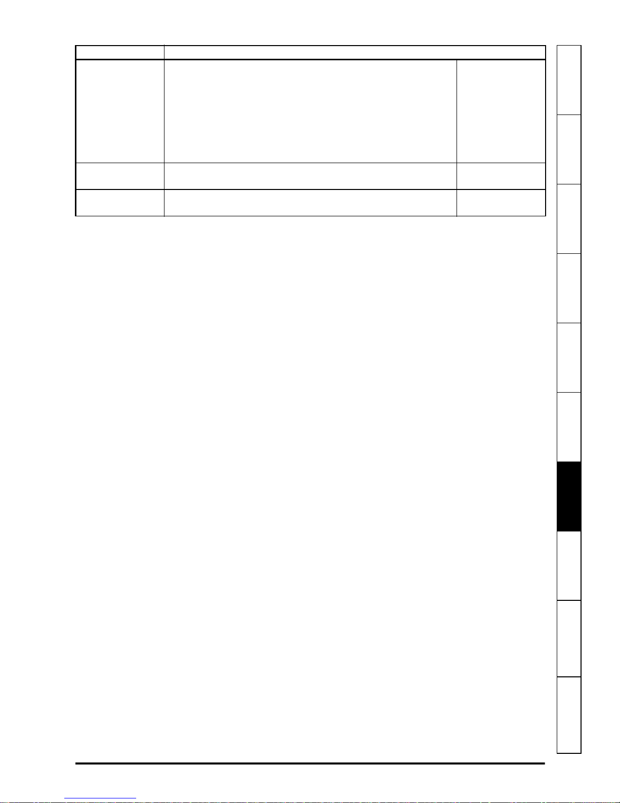
Action Detail
If field weakening is required:
From European defaults:
•Set Pr 59 (Field weakening voltage set point)
Setting up for field
weakening
•Set Pr 69 (minimum flux / voltage limit)
From USA defaults:
•Set Pr 59 (Field weakening voltage set point)
•Set Pr 69 (minimum flux / voltage limit)
•Set Pr 70 ( F i e l d r a te d c u r r en t )
Enable the field
controller
Close field
economy jumper
To enable the field controller:
•Set Pr 77 (Enable field control) = On (1)
Close field economy input (Ion) so that Pr 80 (Economy level
select) is OFF (0).
information
installation
installation
Safety information
Product
Mechanical
Electrical
Getting started Parameters
Setting-up
Technical data Diagnostics UL listing information
FXMP25 User Guide 45
Issue Number: 3 www.controltechniques.com
Page 46

Figure 7-1 Standalone mode logic diagram
03
05
Flux
reference
scaling
04
Flux reference
input offset
Flux
reference
59
Field
weakening
voltage
set point
+
_
02
59
Field
weakeneing
voltage set-point
1
54
Flux
feedback
Voltage error
to % error
conversion
68
68
69
Minimum
flux
Maximum
flux
Compensation
factor
62
P gain
63
I gain
Field
weakening
loop
06
Armature
voltage
Armature voltage
output scaling
07
Field flux
output scaling
Maximum
flux
Maximum
flux
Armature voltage
output Va
Field flux
output If
Armature voltage
feedback
Flux input
Iref
External flux
reference select
64
0
1
+
+
46 FXMP25 User Guide
www.controltechniques.com Issue Number: 3
Page 47

information
Field
economy
level
80
Economy
level
select
5.73
76
AC
supply
5.5858
Field firing
angle
+
_
71
P gain
72
I gain
Flux loop*
Percentage
voltage
demand
57
75
Field voltage
mode select
55
Flux
demand
5.58
60
Field output
voltage
Rated
field
voltage
Vol ta g e t o
firing angle
conversion
73
Field
mode
78
54
Flux
feedback
29
Flux calculator
Motor saturation
breakpoint 1
30
Motor saturation
breakpoint 2
70
Rated field
current
74
Rated field
compensation
factor
56
Field
current
feedback
* Set by autotune Pr
0.12
1
0
0
1
1
0
67
77
0
1
A1/A2
8
81
A1/A2
9
A1/A2
10
F
A
I
L
OR
27
01
25
26
Drive
healthy / OK
1
Ion
installation
installation
Safety information
Product
Mechanical
Electrical
Getting started Parameters
Setting-up
Technical data Diagnostics UL listing information
FXMP25 User Guide 47
Issue Number: 3 www.controltechniques.com
Page 48

Table 7-2 Quick start commissioning / start up from defaults for Mentor MP mode
Action Detail
Ensure:
• Motor field is connected.
Before power up
• The MP port on the FXMP25 is connected to the external
field controller port on the Mentor MP using a shielded
straight through RJ45 to RJ45 lead, maximum length 100 m.
• Mentor MP software must be V01.05.01 or later.
Ensure:
Power up the field
controller
Select Mentor MP
mode
Setting up the field
controller
Setting in MP Set Pr 5.78 to EXTERNAL
• The field controller displays:
• If the field controller trips, see Chapter 9 Diagnostics on
page 60.
To select MP mode
•Set Pr 78 (Field mode) = MP (1)
• Press the mode button to enter parameter view mode
• Press and hold the mode button for at least 2 seconds to
carry out a reset.
The Mentor MP has taken control of the FXMP25. Setting up
should now be carried out using the Mentor MP. Please refer to
the running a motor section in Mentor MP Short Form Guide.
48 FXMP25 User Guide
www.controltechniques.com Issue Number: 3
Page 49

Figure 7-2 Mentor MP mode logic diagram
5.73
76
AC
supply
5.585.58
Field firing
angle
+
_
5.71
P gain
5.72
I gain
Flux loop
54
Flux
feedback
Percentage
voltage
demand
5.57
5.75
Field voltage
mode select
5.55
Flux
demand
5.585.60
Field output
voltage
Rated
field
voltage
Voltage to
firing angle
conversion
5.73
Field
mode
78
5.29
Flux calculator
Motor saturation
breakpoint 1
5.30
Motor saturation
breakpoint 2
5.70
Rated field
current
5.74
Rated field
compensation
factor
56
Field
current
feedback
Field flux
output scaling
A1/A2
If
Field
flux
output
A1/A2
A1/A2
A1/A2
FAI
L
01
Drive
healthy
Enable
field
control
5.77
5
189
10
0
*
07
NOTE
information
installation
installation
Safety information
Product
Mechanical
Electrical
Getting started Parameters
* Flux demand Pr 5.55 is controlled by Mentor MP. Requested bridge is taken from the sign of
Pr 5.55. Positive for the forward bridge and negative (Mentor MP 2 quadrant drives only) for the
Setting-up
Technical data Diagnostics UL listing information
reverse bridge. The bridge change only occurs when the flux is zero.
All parameters except Pr 07 and Pr 78 are set-up by the Mentor MP and therefore
cannot be adjusted on the FXMP25 field controller.
FXMP25 User Guide 49
Issue Number: 3 www.controltechniques.com
Page 50

Table 7-3 Quick start commissioning / start up from defaults for Mentor II mode
Action Detail
Ensure:
• Motor field is connected.
Before power up
• The Mentor II port on the FXMP25 is connected to the
Mentor II using a 10 way IDC to IDC ribbon.
• The supply phases FXMP25 (L1 to L3) are in the same
phase as on the Mentor II (E1 to E3).
Ensure:
Power up the field
controller
Setting up the field
current feedback
scaling
Select Mentor II
mode
Setting up the field
controller
To setup flux OK
relay
• The field controller displays:
• If the field controller trips, see Chapter 9 Diagnostics on
page 60.
• Set parameter Pr 11 on FXMP25 to be the same value as
Pr 6.11 on Mentor II.
To select Mentor II mode
•Set Pr 78 (Field mode) = 2.H (2) for Mentor II mode, half
control (ensure Pr 6.22 on Mentor II is set accordingly).
•Set Pr 78 (Field mode) = 2.F (3) for Mentor II mode, full
control (ensure Pr 6.22 on Mentor II is set accordingly).
• Press the mode button to enter parameter view mode.
• Press and hold the mode button for at least 2 seconds to
carry out a reset.
The Mentor II has taken control of the FXMP25. Setting up
should now be carried out using the Mentor II. Please refer to the
Mentor II User Guide Menu 6.
Set Pr 25 and Pr 26 to the value required. Default values are set
to switch at 10 % current, the same as FXM5.
50 FXMP25 User Guide
www.controltechniques.com Issue Number: 3
Page 51

Figure 7-3 Mentor II mode
54
Flux
feedback
11
Flux calculator
Mentor II field
feedback setting
56
Field
current
feedback
07
Field flux
output scaling
A1/A2
If
Field
flux
output
25 26
27
Flux
level
exceeded
A1/A2
A1/A2
A1/A2
FAI
L
Drive healthy
hysteresis level
Drive healthy
flux level
8
9
10
OR
01
Drive
healthy / OK
WARNING
information
installation
installation
Safety information
Product
Mechanical
Electrical
Getting started Parameters
Refer to Mentor II User Guide Issue 14 page 95 for Mentor II block diagram.
Thermal overload in Mentor II mode works by forcing current feedback to zero causing
the relay to operate. When Mentor II is enabled, this causes the drive to trip FdL (field
loss). When in the disabled state, FdL trip is not active on Mentor II, and therefore
following loss of feedback Mentor II will advance the firing angle to the end stop which
will cause the output of the FXMP to reach maximum voltage set by the front end stop
Pr 6.21.
When using FXMP 25 with Mentor II, Pr 6.21 must be set in order to avoid field over
voltage conditions during fault conditions. (Refer to Pr 6.21 on page 64 in the Mentor II
User Guide for an example calculation). FXMP relay and Mentor II logic functions
should be used to set Pr 6.13 to 0 to disable firing pulses during fault conditions in the
disabled state.
Setting-up
Technical data Diagnostics UL listing information
FXMP25 User Guide 51
Issue Number: 3 www.controltechniques.com
Page 52

FXMP25 Thermal Protection in Mentor 2 Mode.
WARNING
The following parameter setting can be used to provide indication to the Mentor 2 if
overtemperature condition is reached.
Pr 9.23 = 1012 - digital output ST5 set to ‘drive OK / healthy’.
Pr 8.18 = 613 - digital input to control Pr 6.13 (field enable).
Pr 12.03 = 604 - use programmable threshold to detect when firing angle reaches front
end-stop.
Pr 12.04 = 1000.
Pr 9.13 = 806
Pr 9.15 = 1201 - digital output 1 indicates when firing angle end-stop is reached.
Pr 9.07 = 806
Pr 9.09 = 8.11 – drive disabled.
Pr 8.17 = 1034 – force an ‘Et’ trip if FXMP25 relay opens and firing angle reaches endstop and drive is disabled.
Connect digital outputs 1 and 2 and digital input 7 together.
Connect normally open contacts of FXMP25 relay to digital input 6.
52 FXMP25 User Guide
www.controltechniques.com Issue Number: 3
Page 53

8 Technical data
21.5
16
0
5
10
15
20
25
30
0 102030405060
Ambient temperature( C)°
Permissable output current (A)
8.1 Ratings
The continuous output current rating given is for a maximum ambient temperature of
40 °C (104 °F) and an altitude of 1000 m. For operation at higher temperatures and
altitudes derating is required.
Maximum continuous input current
The value of the maximum continuous input current is given to aid the selection of
cables and fuses. The value is stated for worst-case conditions.
Continuous AC
input current
A
26 25
8.2 FXMP25 derating for extended ambient operation
Figure 8-1 FXMP25 derating for extended ambient operation
Continuous DC
output current
A
information
installation
installation
Safety information
Product
Mechanical
Electrical
Getting started Parameters Setting-up
8.3 Power dissipation
FXMP25 User Guide 53
Issue Number: 3 www.controltechniques.com
Table 8-1 shows the maximum field controller losses, assuming 480 V supply on a
300 V field.
Table 8-1 Field controller losses
Loss @ 40 °C Loss @ 50 °C Loss @ 55 °C
WWW
85.5 81.6 73.6
Technical data
Diagnostics UL listing information
Page 54

8.4 AC supply requirements
NOTE
CAUT ION
The FXMP25 is rated for a nominal supply up to 480 Vrms.
8.4.1 Supply types
The FXMP25 is suitable for use with any supply type, i.e. TN-S, TN-C-S, TT, IT, with
grounding at any potential, i.e. neutral, centre or corner (grounded-delta).
8.4.2 AC supply specification
Table 8-2 AC supply
Specification Product voltage variant
Maximum nominal supply 480 V
Tol e r a nc e 10 %
Minimum nominal supply 208 V
Tol e r a nc e -1 0 %
8.5 Line reactors
The FXMP25, in common with all naturally commutated SCR drives, causes voltage
notches at the input supply terminals. To avoid disturbances with other equipment using
the same supply, the addition of external line inductance is strongly recommended in
order to restrict the depth of notches imposed. This is generally not necessary where a
dedicated transformer is used to supply the FXMP25.
The following recommendations for added line inductance, have been calculated based
on the power drive systems standard: EN 61800-3:2004 "Adjustable speed electrical
power drive systems - Part 3: EMC requirements and specific test methods".
Table 8-3 Minimum values of L
application
Field output
current
add
400 V 480 V
and inductor current rating for a typical
System voltage Typical current
rating
A μH μH A
25 230 290 26
On typical field windings or high inductance loads the output current is smooth DC and
therefore the rms input current is approximately equal to the DC output current.
The above assumes the supply has 1.5 % impedance and a minimum supply rating of
5 kA.
Control of currents below 250 mA (thyristor holding currents) should be avoided. If
control at this level is required then line reactors must be installed to reduce the effect
of dv/dt as thyristors turn off.
54 FXMP25 User Guide
www.controltechniques.com Issue Number: 3
Page 55

8.6 Temperature and humidity
Ambient temperature operating range:
0 °C to 55 °C (32 °F to 131 °F)
Field output current derating must be applied at temperature >40 °C (104 °F).
Safety information
Minimum temperature at power-up:
The FXMP25 will power up at -15 °C (5 °F).
Maximum humidity:
The FXMP25 can operate in environments up to a maximum relative humidity: 90 %
non-condensing at 50 °C.
8.7 Storage
Storage temperature range: -40 to 70 °C.
Storage time is 2 years.
Electrolytic capacitors in any electronic product have a storage period after which they
require reforming or replacing.
The DC bus capacitors have a storage period of 10 years.
The low voltage capacitors on the control supplies typically have a storage period of 2
years and are thus the limiting factor.
Low voltage capacitors cannot be reformed due to their location in the circuit and thus
may require replacing if the FXMP25 is stored for a period of 2 years or greater without
power being applied.
It is therefore recommended that the FXMP25 is powered up for a minimum of 1 hour
after every 2 years of storage.
information
installation
installation
Product
Mechanical
Electrical
Getting started Parameters Setting-up
This process allows the FXMP25 to be stored for a further 2 years.
8.8 Altitude
Altitude range: 0 to 3,000 m (9,900 ft), subject to the following conditions:
1,000 m to 3,000 m (3,300 ft to 9,900 ft) above sea level: de-rate the maximum
output current from the specified figure by 1 % per 100m (330 ft) above 1,000 m
(3,300 ft)
For example at 3,000 m (9,900 ft) the output current of the drive would have to be derated by 20 %.
8.9 IP rating
The FXMP25 is rated to IP20 pollution degree 2 (dry, non-conductive contamination
only).
The IP rating of a product is a measure of protection against ingress and contact to
foreign bodies and water. It is stated as IP XX, where the two digits (XX) indicate the
degree of protection provided as shown in Table 8-4.
Technical data
Diagnostics UL listing information
FXMP25 User Guide 55
Issue Number: 3 www.controltechniques.com
Page 56

Table 8-4 IP rating degrees of protection
NOTE
First digit Second digit
Protection against contact and
ingress of foreign bodies
0 No protection 0 No protection
Protection against large
foreign bodies φ > 50 mm
1
(large area contact with the
hand)
Protection against medium
2
size foreign bodies φ > 12 mm
(finger)
Protection against small
3
foreign bodies φ > 2.5 mm
(tools, wires)
Protection against granular
4
foreign bodies φ > 1 mm
(tools, wires)
Protection against dust
5
deposit, complete protection
against accidental contact.
Protection against dust
6
ingress, complete protection
against accidental contact.
7 - 7 Protection against immersion
8 - 8 Protection against submersion
Protection against ingress of water
Protection against vertically
1
falling drops of water
Protection against spraywater
2
(up to 15 ° from the vertical)
Protection against spraywater
3
(up to 60 ° from the vertical)
Protection against splashwater
4
(from all directions)
Protection against heavy
5
splash water (from all
directions, at high pressure)
Protection against deckwater
6
(e.g. in heavy seas)
8.10 Corrosive gasses
Concentrations of corrosive gases must not exceed the levels given in:
• Table A2 of EN 50178:1998
• Class 3C2 of IEC 60721-3-3
This corresponds to the levels typical of urban areas with industrial activities and/or
heavy traffic, but not in the immediate neighborhood of industrial sources with chemical
emissions.
8.11 RoHS compliance
FXMP25 meets EU directive 2002-95-EC for RoHS compliance.
8.12 Vibration
Maximum recommended continuous vibration level 0.14 g rms broad-band 5 to 200 Hz.
This is the limit for broad-band (random) vibration. Narrow-band vibration at this level
which coincides with a structural resonance could result in premature failure.
56 FXMP25 User Guide
www.controltechniques.com Issue Number: 3
Page 57

Bump test
Testing in each of three mutually perpendicular axes in turn.
Referenced standard:IEC 60068-2-29: Test Eb:
Severity: 18 g, 6 ms, half sine
No. of Bumps: 600 (100 in each direction of each axis)
Safety information
Random vibration test
Testing in each of three mutually perpendicular axes in turn.
Referenced standard:IEC 60068-2-64: Test Fh:
Severity: 1.0 m
2/s3
(0.01 g2/Hz) ASD from 5 to 20 Hz
-3 dB/octave from 20 to 200 Hz
Duration: 30 minutes in each of 3 mutually perpendicular axes.
Sinusoidal vibration test
Testing in each of three mutually perpendicular axes in turn.
Referenced standard: IEC 60068-2-6: Test Fc:
Frequency range: 5 to 500 Hz
Severity: 3.5 mm peak displacement from 5 to 9 Hz
10 m/s
2
peak acceleration from 9 to 200 Hz
15 m/s2 peak acceleration from 200 to 500 Hz
Sweep rate: 1 octave/minute
Duration: 15 minutes in each of 3 mutually perpendicular axes.
EN 61800-5-1:2007, Section 5.2.6.4. referring to IEC 60068-2-6
Frequency range: 10-150 Hz
Amplitude: 10-57 Hz @ 0.075 mm pk
57-150 Hz @ 1g pk
Sweep rate: 1 octave/minute
Duration: 10 sweep cycles per axes in each of 3 mutually
perpendicular axes
information
installation
installation
Product
Mechanical
Electrical
Getting started Parameters Setting-up
8.13 Acoustic noise
The internal fan generates the majority of the acoustic noise produced by the field
controller.
FXMP25 sound pressure level at 1 m = 44.5 dBA.
8.14 Overall dimensions
Refer to Figure 3-3 Overall dimensions on page 13.
8.15 Weight
The overall weight of the FXMP25 is 1.70 kg (3.70 Ib).
8.16 Cable and fuse size ratings
Refer to section 4.5 Cable and fuse size ratings on page 18.
Technical data
Diagnostics UL listing information
FXMP25 User Guide 57
Issue Number: 3 www.controltechniques.com
Page 58

8.17 Electromagnetic compatibility (EMC)
This is a summary of the EMC performance of the FXMP25. For full details, refer to the
FXMP25 EMC data sheet which can be obtained from the supplier of the FXMP25.
Table 8-5 Immunity compliance
Standard
EN 61000-4-2
IEC 61000-4-2
EN 61000-4-3
IEC 61000-4-3
EN 61000-4-4
IEC 61000-4-4
EN 61000-4-5
IEC 61000-4-5
EN 61000-4-6
IEC 61000-4-6
EN 61000-4-11
IEC 61000-4-11
EN 61000-4-8
IEC 61000-4-8
EN 61000-61:2007
IEC 61000-6-1
EN 61000-62:2005
IEC 61000-6-2
EN 618003:2004
IEC 61800-3
1
See section 4.6.1 Surge immunity of control circuits - long cables and connections
outside a building on page 22 for control ports for possible requirements regarding
grounding and external surge protection.
Type of
immunity
Electrostatic
discharge
Radio
frequency
radiated field
Fast transient
burst
Surges
Conducted
radio
frequency
Voltage dips,
short
interruptions
& variations
Power
frequency
magnetic
field
Generic immunity standard for the residential,
commercial and light - industrial environment
Generic immunity standard for the industrial
Product standard for adjustable speed power drive
systems (immunity requirements)
repetition frequency via coupling
repetition frequency by direct injection
Test specification Application Level
6 kV contact discharge
8 kV air discharge
80 % AM (1 kHz) modulation
Levels prior to modulation:
10V/m 80 - 1000 MHz
3V/m 1.4 – 2.0 GHz
1V/m 2.0 – 2.7 GHz
5/50ns 2 kV transient at 5 kHz
clamp
5/50ns 2 kV transient at 5 kHz
Common mode 4 kV
1.2/50 μs waveshape
Differential mode 2 kV
Common mode 1 kV
10 V prior to modulation
0.15 - 80 MHz
80 % AM (1 kHz) modulation
All durations AC supply lines
Exceeds level 5
environment
Module
enclosure
Module
enclosure
Control lines
Power lines
AC supply lines:
line to ground
AC supply lines:
line to line
Control lines
Control and
power lines
Module
enclosure
Meets immunity requirements for
first and second environments
1
Level 3
(industrial)
Level 3
(industrial)
Level 4
(industrial
harsh)
Level 3
(industrial)
Level 4
Level 3
Level 3
(industrial)
Level X
(1mT)
Complies
Complies
58 FXMP25 User Guide
www.controltechniques.com Issue Number: 3
Page 59

Emission
CAUT ION
The following standards are met for cable lengths up to 100m.
Table 8-6 FXMP25 emission compliance
Filter Conformity
No filter C4
Schaffner FN3280H-25-33 C2
Filters can be sourced directly from Schaffner.
Key (shown in decreasing order of permitted emission level):
Safety information
information
Product
C4 EN 61800-3:2004 second environment, restricted distribution (Additional
measures may be required to prevent interference).
C2 Industrial generic standard EN 61000-6-4:2007.
EN 61800-3:2004 first environment restricted distribution (The following caution
is required by EN 61800-3:2004).
This is a product of the restricted distribution class according to IEC 61800-3. In a
residential environment this product may cause radio interference in which case the
user may be required to take adequate measures.
EN 61800-3:2004 defines the following:
• The first environment is one that includes residential premises. It also includes
establishments directly connected without intermediate transformers to a lowvoltage power supply network which supplies buildings used for residential
purposes.
• The second environment is one that includes all establishments other than those
directly connected to a low-voltage power supply network which supplies buildings
used for residential purposes.
• Restricted distribution is defined as a mode of sales distribution in which the
manufacturer restricts the supply of equipment to suppliers, customers or users who
separately or jointly have technical competence in the EMC requirements of the
application of drives.
installation
installation
Mechanical
Electrical
Getting started Parameters Setting-up
FXMP25 User Guide 59
Issue Number: 3 www.controltechniques.com
Technical data
Diagnostics UL listing information
Page 60

9 Diagnostics
WARNING
M
STORED CHARGE
10 min
Mode /Reset
FXMP25
FXMP25 status
= tripped
Trip type
(FdL =Field loss)
The display on the FXMP25 gives various information about the status of the field
controller. These fall into three categories:
• Trip indications
• Alarm indications
• Status indications
Users must not attempt to repair a faulty FXMP25 or carry out fault diagnosis other than
replace internal fuses or through the use of the diagnostic features described in this
chapter. Under no circumstances must the casing of the FXMP25 be opened when the
AC supply is connected. Faulty units must be returned to an authorized Control
Techniques distributor for repair.
9.1 Trip indications
If the unit trips, the field output is disabled and the FXMP25 ceases to control the field.
The left hand display indicates that a trip has occurred, and the right hand display
shows the trip.
Trips are listed alphabetically in Table 9-1 based on the trip indication shown on the
FXMP25 display.
Example
The FXMP25 display shows an FdL trip on the display as shown in Figure 9-1 below:
Figure 9-1 Typical example of trip display
The above graphic shows the resultant display following an FdL trip. This indicates a
field loss condition as described in Table 9-1 on page 61 overleaf.
60 FXMP25 User Guide
www.controltechniques.com Issue Number: 3
Page 61
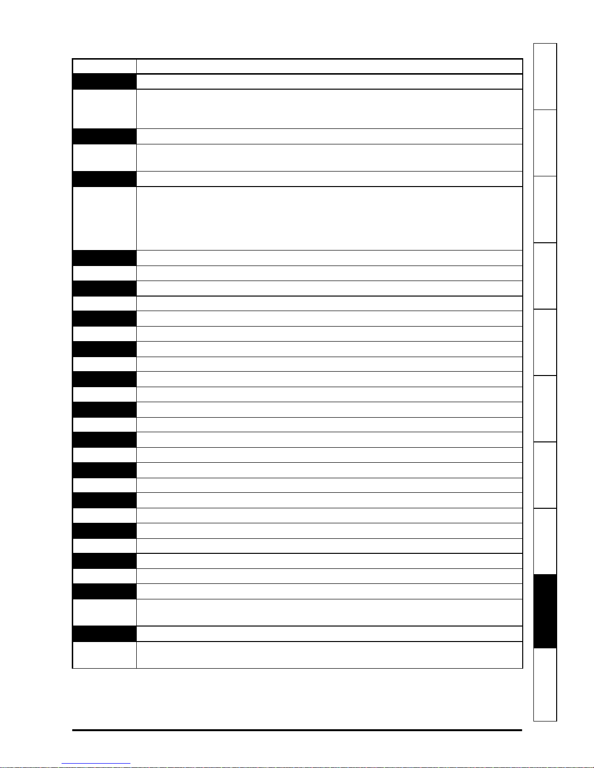
Table 9-1 Trip indications
Trip Diagnosis
EEF
Internal EEPROM trip
Internal FXMP25 EEPROM checksum. When this trip occurs all the parameters are set to
default. The trip can only be removed by entering a load default command (i.e. Eur or
USA) into Pr 00 before re-setting the FXMP25.
FdL
No current in the field supply circuit
Check the field circuit.
Check the FXMP25 internal fuses.
FOC
Excess current detected field current feedback
Maximum field current is present.
Check the field rated current (Pr 70) and the field rated voltage (Pr 73) are set correct to
the motor nameplate.
Check for short circuit on field circuit cabling.
Check integrity of motor insulation.
HF06
Unexpected interrupt
Hardware fault - return to supplier
HF07
Watchdog failure
Hardware fault - return to supplier
HF08
Interrupt clash
Hardware fault - return to supplier
HF11
Access to the EEPROM failed
Hardware fault - return to supplier
HF17
No comms from power processor
Hardware fault - return to supplier
HF19
Flash failure
Hardware fault - return to supplier
HF21
Power processor - Watchdog failure
Hardware fault - return to supplier
HF22
Power processor - Unexpected interrupt
Hardware fault - return to supplier
HF23
Power processor - Level overrun
Hardware fault - return to supplier
HF24
Power processor - No frequency at power up
Hardware fault - return to supplier
HF29
Fan fault
Hardware fault - return to supplier
O.ht1
FXMP25 overheat (SCR junction) based on thermal model
• Reduce ambient temperature or field current
• Check the fans are operating and venting is not blocked
O.ht2
Heatsink over temperature
• Reduce ambient temperature or field current
• Check the fans are operating and venting is not blocked
Safety information
information
Product
Mechanical
installation
installation
Electrical
Getting started Parameters Setting-up Technical data
Diagnostics
UL listing information
FXMP25 User Guide 61
Issue Number: 3 www.controltechniques.com
Page 62

Trip Diagnosis
OV
PS
PS.24
Tune
Over voltage
• Check AC supply is within specification
• Check that notching on the AC supply is not excessive. Refer to section 8.5 Line
reactors
Internal FXMP25 power supply trip
Return to the supplier
24V comms power supply overload
Check connection to the Mentor MP / serial port connector
Autotune stopped before completion
See Pr 12 (Autotune)
on page 54
9.2 Trip categories
Trips can be grouped into the following categories. It should be noted that a trip can only
occur when the FXMP25 is not tripped or is already tripped but with a trip with a lower
priority number.
Table 9-2 Trip categories
Priority Category Trips Comments
1 Hardware faults HF01 to HF11
2
3
4EEF trip EEF
5Normal trips
Self resetting
trips
Non-resetable
trips
UV
HF17 to HF29 Cannot be reset
All other trips not
included in this
table
These indicate fatal problems and cannot
be reset. The FXMP25 is inactive after
one of these trips and the display shows
HFxx.
Under voltage trip cannot be reset by the
user, but is automatically reset by the
FXMP25 when the supply voltage is
within specification.
Cannot be reset unless a code to load
defaults is first entered in Pr 00
Can be reset after 1.0s
Unless otherwise stated, trips cannot be reset until 1.0s after the trip has been triggered
by the FXMP25
9.3 Alarm indications
Table 9-3 Alarm indications
Right hand
display
hot
The heatsink temperature is approaching the over temperature threshold
(see O.ht2).
FAIL
An attempt has been made to default the FXMP25 when it is enabled
[Pr 77 = On (1)].
n.SEr
The FXMP25 cannot communicate with the Mentor MP
62 FXMP25 User Guide
Description
Heatsink temperature too high
Load default when the FXMP25 is active
No communication between FXMP25 and Mentor MP
www.controltechniques.com Issue Number: 3
Page 63

9.4 Status indications
Table 9-4 Status indications
Safety information
Left hand
display
ih
The field controller is inhibited because the field controller is disabled
[Pr 77 = OFF (0)].
tr
The field controller has tripped. The trip code will be displayed in the ‘right
hand’ display (see Chapter 9 Diagnostics on page 60).
rn
The field controller is in a run state.
Pr 78 = Mode Selected and
Pr 77 = On (1) in Standalone Mode or
Mentor MP Pr 5.77 = On (1) In MP Mode or
Mentor II ribbon cable is connected in Mentor II mode.
Field controller inhibited
Field controller has tripped
Field controller is running
9.5 Displaying the trip history
The FXMP25 retains the last four trips that have occurred. Table 9-5 shows parameters
used to store the last four trip.
Table 9-5 Trips
Parameter Description
90 Trip 0 (most recent trip)
91 Trip 1
92 Trip 2
93 Trip 3
Description
information
Product
Mechanical
installation
installation
Electrical
Getting started Parameters Setting-up Technical data
9.6 Behavior of the FXMP25 when tripped
If the FXMP25 trips the output of the FXMP25 is disabled so that the FXMP25 stops
controlling the field. If any trip occurs the following read only parameters are frozen to
help in diagnosing the cause of the trip.
Table 9-6 Parameters frozen on trip
Parameter Description
02 Armature voltage
54 Flux feedback
56 Field current feedback
58 Field firing angle
03 Flux reference
Analog and digital I/O
The analog and digital I/O on the FXMP25 continue to work correctly if a trip occurs.
Diagnostics
UL listing information
FXMP25 User Guide 63
Issue Number: 3 www.controltechniques.com
Page 64

10 UL listing information
FXMP field controller has been assessed to comply with both URus and cUR
requirements.
Control Techniques UL file number is E171230. Confirmation of UL recognition can be
found at website: www.ul.com.
10.1 Conditions of acceptability
Conformity: The field controller conforms to UL recognition requirements only when the
following are observed.
1. The Device shall be installed in a pollution degree 2.
2. The terminal torques specified in section 3.2 Electrical terminals on page 14 are to
be used.
3. Field wiring is to be class 1, 75 °C copper wire only
4. The field controller is to be installed in an enclosure having adequate strength and
thickness to the intended manner and with acceptable spacings provided.
5. This unit has been tested together with the Mentor MP range of DC drives for field
loss detection. When other DC drives are used, loss of field current or voltage
detection shall be provided, this detection shall prevent motor over speed upon field
loss.
6. FS1 and FS2 shall be fuse type FR10GR69V30 by Ferraz Shawmut (E76491),
rated 30 A, 690 Vac.
7. Suitable for use on a circuit capable of delivering not more than 100 kA RMS
symmetrical Amperes, 480 Vac maximum. When protected by a class CC fuse with
an IAC rating of 100 kA minimum and rated at 30 A maximum.
8. The surrounding air temperature of the device does not exceed 40 °C when the
device is operating.
9. BCP fusing is to be provided in accordance with NEC requirements.
10.2 AC supply specification
The maximum UL supply voltage is 480 Vac.
The device is suitable for use in a circuit capable of delivering not more than 100,000
rms symmetrical amperes at 480 Vac when installed as per point 7 above in section
10.1.
10.3 Maximum continuous current
The device is listed as having the maximum continuous current ratings as specified in
section 2.1 Ratings on page 9.
64 FXMP25 User Guide
www.controltechniques.com Issue Number: 3
Page 65

Page 66

0476-0009-03
 Loading...