

Page 1
D4 Valve
D103039X012
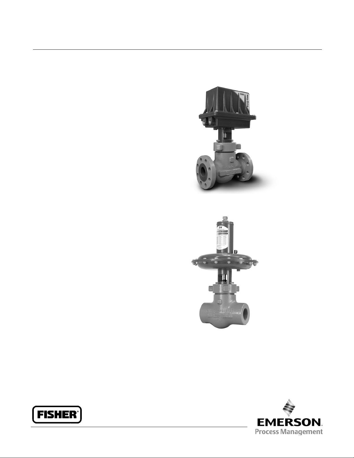
Fisherr D4 Control Valve Assembly
The Fisher D4 control valve is a compact, rugged globe
valve designed primarily for high-pressure throttling
applications using either pneumatic or electric control.
This valve is ideal for use on pressure and flow control
applications within the oil and gas production industry.
The D4 is an excellent control valve for high-pressure
separators, scrubbers, and other processing
equipment. These valves are especially useful for
either throttling or on/off control of liquids or gases
which are gritty, sticky, or which have a tendency to
builduponinternalvalveparts.
If the control valve requires maintenance, the trim and
packing can be maintained by removing the deep-bore
hammer nut and lifting the actuator/bonnet assembly
off the valve without disassembling the actuator.
W9933-1
Product Bulletin
51.2:D4
November 2013
Features
Electric and Pneumatic
Safer Bonnet / Valve Body Connection– Unique
design provides additional protection if disassembly
of bonnet/valve body connection is inadvertently
started while there is still pressure in the valve body.
Pins mounted in the valve bonnet help ensure the
bonnet disengages from the valve body as the
hammer nut is removed, while the threads are still
engaged.
Heavy-Duty Guiding–Massive guiding (figures 1 and
2) positively aligns the valve plug in the seat ring for
reliable service. The screwed-in seat ring completely
encloses the seat ring gasket.
Live-loaded Packing System–The packing system
provides an improved stem seal to help prevent the
loss of valuable or hazardous process fluids or gases.
It features Fisher ENVIRO-SEALt packing
technology to provide reduced packing
maintenance.
FISHER D4 CONTROL VALVE WITH easy-Drive™ ELECTRIC
ACTUATOR (NPS 2 RF FLANGED END CONNECTION)
W8531
FISHER D4 CONTROL VALVE
(NPS 2 NPT END CONNECTION)
www.Fisher.com
Page 2

Product Bulletin
51.2:D4
November 2013
D4 Valve
D103039X012
Features (continued)
Electric and Pneumatic
NACE Constructions–NACE compatible trim is
available with the D4 control valve. These
constructions meet the metallurgical requirements
of NACE MR0175 / ISO 15156.
Quick-Change Valve Plug–Removable groove pin
allows quick, easy valve plug replacement.
Severe Service Capability with Tungsten Carbide
Trim–D4 valves are available with tungsten carbide
trim for erosive service. This trim is designed
specifically for severe service applications in the oil
and gas industry. Durable tungsten carbide trim
may benefit your application by wearing better and
lasting longer.
Easy Installation–Compact design allows
installation where space is a premium. Screwed
valve bodies feature compact face-to-face
dimensions while flanged valve bodies conform to
ISA-75 standards for maximum versatility.
Electric
Low Power Consumption-- The Fisher easy-Drive
electric actuator operates with 12 or 24VDC and
less than 0.1 watt hours per operation, using
Modbus,4-20mA,1-5VDC,ordrycontactcontrol
signals.
Low Temperature-- Theeasy-Driveelectricactuator
design allows use in ambient temperatures as low
as -20C(-4F) without use of a heater.
Easy Installation--The compact design allows
installation where space is a premium. Fisher
easy-Drive calibrates by simply opening and closing
the valve.
Remote Monitoring and Configuration-- Loss of
signal position is programmable over Modbus.
Pneumatic
Easy Maintenance–Hammer nut bonnet/body joint
allows repair or maintenance with a minimum of
tools, without removing the valve body from the
piping system. Seat ring can be removed with the
same service tools used with a Fisher D valve.
Integral Bonnet Flange– Bonnet has an integral
flange that accepts hammer nut force when making
the bonnet-to-body connection. There are no snap
rings subject to possible failure in sour service or in
atmospheric corrosion.
Standard Trim for Throttling or On-Off Service–
Micro-Form trim is standard for throttling or on-off
service at no extra cost.
Application Flexibility–Choices of port diameters up
to 31.8 mm (1.25 inches), end connections, and
trim materials suit these valves to many
applications, including sour service.
Low Temperature Materials--Valve construction
materialsallowuseinapplicationsaslowas-40C
(-40F) for the pneumatic actuator.
Installation
D4 control valves may be installed in any position, but
normally the actuator is vertical and above the valve.
Install the control valve so the flow direction arrow on
thesideofthevalvebodyindicatesthedirectionofthe
process flow.
Dimensions are shown in tables 12 and 13 and
figures 1 and 2.
2
Page 3

D4 Valve
D103039X012
Valve Specifications
Product Bulletin
51.2:D4
November 2013
Available Actuation Configurations
Spring-To-Close Pneumatic
Flow Coefficients
See Fisher Catalog 12
Spring-To-Open Pneumatic
Electric
Valve Sizes and End Connection Styles
(1)
See table 3
Dimensions
See tables 12 and 13 and figures 1 and 2.
Face-to-face dimensions for flanged valves conform
to ISA-75.03 (CL150-600) and ANSI/ISA-75.16 Short
(CL900/1500)
Maximum Inlet Pressures and Temperatures
(1)
Flanged connections are consistent with the ASME
B16.34 pressure-temperature class, subject to
Material Temperature Capabilities for the Valve Body
Assembly (see following specification). For NPT end
connections, the valve body rating is 4250 psig.
Maximum Pressure Drops
(1)
Seetables7,8,9,10,and11
Shutoff Classification per ANSI/FCI 70-2
and IEC 60534-4
Class IV
Flow Characteristic
Equal percentage
Flow Direction
Flow up only
1. The pressure or temperature limits in the referenced tables andany applicable ASME code limitations should not be exceeded.
Port Diameters
See table 3
Construction Materials
Valve Body and Bonnet: ASME SA 352 LCC
Valve Plug and Seat: See table 5
Valve Stem: S20910
Actuator O-Rings: (HNBR) Hydrogenated Nitrile
Bonnet O-Ring:
Standard: HNBR
Optional: Fluorocarbon
Packing: PTFE/Carbon PTFE
Packing Springs: N07718
Packing Retainer: S17400
Actuator Diaphragm: Chloroprene
Actuator Spring: Painted steel
Seat Ring Gasket: S31600 (316 SST)
Spring Cover (Fail Up): PVC
Valve Plug Travel
19 mm (0.75 inch)
Valve Plug Style
Micro-Form valve plug
Material Temperature Capabilities
Valve Body Assembly:
Standard Bonnet O
(-40 to 275F)
Optional Bonnet Fluorocarbon O
-23 to 204C(-10to400F)
-
Ring: -40 to 135C
-
Ring:
3
Page 4

Product Bulletin
51.2:D4
November 2013
Actuator Specifications
D4 Valve
D103039X012
ELECTRIC ACTUATOR
Material Temperature Capabilities
Electric Actuator Assembly:
-20 to 70C(-4to158F) ambient
(1)
Electromagnetic Compatibility
Meets EN 61326-1 (First Edition)
Immunity: Industrial locations per table 2 of EN
61326-1 Standard. Performance is shown in table 2
Emmissions: Class A
ISM Equipment Rating: Group 1, Class A
Available Electric Actuator Configurations
easy-Drive Electric On/Off
easy-Drive Electric Positioning
Power Requirements
12 or 24VDC, minimum 4 amp power supply required
(fuse to 5 amps)
Maximum Current Draw
4amps
Conduit Connections
Two 3/4 NPT connections
PNEUMATIC
Input Signal to Actuator
Seetables7,8,9,and10
Material Temperature Capabilities
Actuator Assembly:
Fail-Down, Spring-to-Close: -40 to 93C
(-40 to 200F)
Fail-Up, Spring-to-Open: -40 to 93C
(-40 to 200F)
Control Signals
On/Off: Dry contact, Modbus RTU
Positioning: 1-5VDC, 4-20 mA, Modbus RTU
Available Pneumatic Actuator Configurations
Spring-to-Open
Electrical Classification
Spring-to-Close
Hazardous Area:
CSA (C/US) – Explosion proof
FM– Explosion proof (pending)
ATEX– Flameproof (pending)
Maximum Actuator Casing Pressure
3.4 bar (50 psig)
IECEx– Flameproof (pending)
Refer to table 1 for specific approval information
Electrical Housing:
Actuator Diaphragm Effective Area
452 cm
2
CSA -- Type 4X
FM -- NEMA 4X (pending)
ATEX -- IP66 (pending)
IECEx -- IP66 (pending)
1. The pressure or temperature limits in the referenced tables andany applicable ASME code limitations should not be exceeded.
Actuator Pressure Connections
1/4 NPT internal
ACTUATOR
(1)
(1)
(69 square inches)
4
Page 5

D4 Valve
D103039X012
Table 1. Hazardous Area Classifications - CSA (Canada and United States)
CERTIFICATION BODY
CSA Class I,Division 1, GP C, D T6 ---
Table 2. EMC Summary Results - Immunity
PORT PHENOMENON BASIC STANDARD TEST LEVEL
Electrostatic discharge (ESD) IEC 61000-4-2
CERTIFICATION
OBTAINED
ENTITY RATING TEMPERATURE CODE ENCLOSURE RATING
T6 (Tamb ≤ 70_C)
4kV Contact
8kV Air
Product Bulletin
51.2:D4
November 2013
CSA Type 4X Enclosure
PERFORMANCE
CRITERIA
(1)
A
Enclosure
I/O signal/ control
Performance criteria is +/- 5% stem position
1. A= No degradation during testing. B = Temporary degradation during testing, but is self recovering.
2. Criteria A with conduit on DC and I/O cables, CriteriaB without conduit
Radiated EM field IEC 61000-4-3
Rated powerfrequency
magnetic field
Burst IEC 61000-4-4 1kV A
Surge IEC 61000-4-5 1kV cable shield, and line to ground A
Conducted RF IEC 61000-4-6 3V 150 kHz to 80 MHz at 3 Vrms A
IEC 61000-4-8 30 A/m@ 50 and 60 Hz A
Ordering Information
When ordering, specify:
Application Information
1. Type of application
a. Throttling or on-off
b. Reducing or relief (back pressure)
2. Controlled fluid
80 to1000 MHz @ 10V/m 1kHz AM at 80%
1400 to2000 MHz @ 3V/m 1kHz AM at 80%
2000 to2700 MHz @ 1V/m 1kHz AM at 80%
a. Range of flowing pressure drops
b. Maximum drop at shutoff
5. Flow rates
a. Minimum controlled flow
b. Normal flow
c. Maximum flow
(2)
A
/B
a. Type (include chemical analysis, if available)
b. Temperature (normal and maximum
anticipated)
c. Specific gravity
3. Range of flowing inlet pressures
4. Pressure drops
6. Input signal range to actuator
Control Valve Assembly Information
Refer to the Specifications and review the information
under each specification.
5
Page 6

Product Bulletin
51.2:D4
November 2013
Table 3. Valve Sizes and Connection Styles
VALVE
SIZE,
NPS
1
2
X = Available construction.
PORT
DIAMETER,
(INCHES)
0.25, 0.375,
0.5, 0.75
0.25, 0.375,
0.5, 0.75, 1,
1.25
Table 4. Fisher D4 Control Valves Approximate Weights, Kg (Pounds)
Valve Body Size, NPS
Screwed 32 (71) 39 (87) 22 (49) 29 (64)
CL150 34 (74) 39 (86) 24 (52) 29 (63)
CL300 and 600 37 (81) 48 (106) 27 (59) 33 (73)
CL900 and 1500 50 (110) 66 (146) 40 (88) 51 (113)
SCREWED RAISED FACE (RF) FLANGED
4250 psi CL150 CL300 CL600
X X X X X X X
X X X X X X X
Pneumatic Electric
1 2 1 2
CL900 and
1500
CL600
D4 Valve
D103039X012
RING TYPE JOINT
(RTJ) FLANGE D
CL900 and
1500
Table 5. Typical Combinations of Metal Trim Parts
DESIGNATION VALVE PLUG SEAT RING
Standard S41600 hardenedto 38 HRC minimum S17400
Sour S17400 (NACE MR0175/ISO 15156) S17400 (NACE MR0175/ISO 15156)
Tungsten Carbide Tungsten carbide / S17400(NACE MR0175/ISO15156) Tungsten carbide / S17400 (NACE MR0175/ISO15156)
Table 6. Fisher D4 Environmental Limits for NACE MR0175/ISO 15156 with Sour Trim
MAXIMUM TEMPERATURE MAXIMUM H2S PARTIAL PRESSURE
_C _F MPa psia
204 400 1.4 200 No
199 390 2.3 330 No
191 375 2.5 360 No
149 300 2.8 400 No
135 275 No Limit Yes
Table 7. Maximum Shutoff Pressure Drops
When Used with Typical Control Instrumentation
INPUT SIGNAL TO
ACTUATOR
SPRING Light Rate Heavy Rate
INITIAL SPRING
SETTING
PORT DIAMETER Maximum PressureDrop
mm Inches Bar Psi Bar Psi Bar Psi Bar Psi Bar Psi Bar Psi
6.4
9.5
12.7
19.1
25.4
31.8
1. The pressure or temperature limits in the referenced tables and any applicable ASMEcode limitations shouldnot be exceeded.
2. For example, use the column marked 0-1.4 bar (0-20 psig) for a 0.21-1.0 bar (3-15 psig) pneumatic controller with1.4 bar (20 psig) supply pressure.
3. For applications with downstream pressure in excess of 196 bar (2845 psig), use 196 bar (2845 psig) forMaximum Shutoff Pressure.
0.25
0.375
0.5
0.75
1
1.25
0to1.2Bar
(0 to 18 Psig)
0.77 Bar
(11.2 Psig)
(3)
293
(3)
293
191
80
42
25
4250
4250
2765
1160
610
365
(3)
(3)
(1)
0to1.4Bar
(0 to 20 Psig)
0.77 Bar
(11.2 Psig)
(3)
293
(3)
293
191
80
42
25
for Fisher D4 Control Valves with Pneumatic Actuator (Spring-to-Close)
(2)
4250
4250
2765
1160
610
365
(3)
(3)
0to2.0Bar
(0 to 30 Psig)
0.85 Bar
(12.4 Psig)
293
293
219
92
49
30
4250
4250
3180
1340
715
430
0to2.3Bar
(0 to 33 Psig)
1.05 Bar
(15.3 Psig)
293
293
288
123
67
41
4250
4250
4180
1785
965
590
0to2.4Bar
(0 to 35 Psig)
1.18 Bar
(17.1 Psig)
293
293
293
143
78
48
COMPATIBLE WITH
ELEMENTAL SULFUR?
0to3.4Bar
(0 to 50 Psig)
1.18 Bar
(17.1 Psig)
4250
4250
4250
2080
1130
700
293
293
293
143
78
48
4250
4250
4250
2080
1130
700
6
Page 7

D4 Valve
D103039X012
Product Bulletin
51.2:D4
November 2013
Table 8. Maximum Shutoff Pressure Drops
When Used with Instrumentation with Restricted Output Range
INPUT SIGNAL TO ACTUATOR
SPRING Heavy Rate Heavy Rate
INITIAL SPRING SETTING
PORT DIAMETER Maximum Pressure Drop
mm Inches Bar Psi Bar Psi
6.4
9.5
12.7
19.1
25.4
31.8
1. The pressure or temperature limits in the referenced tables and any applicable ASMEcode limitations shouldnot be exceeded.
2. For example, an Electro-PneumaticTransducer calibrated for 0.4-2.0bar (6-30 psig) outputpressure.
3. For applications with downstream pressure in excess of 118 bar (1715 psig), use 118 bar (1715 psig) forMaximum Shutoff Pressure.
0.25
0.375
0.5
0.75
1
1.25
Table 9. Maximum Shutoff Pressure Drops
When Used with Typical Control Instrumentation
INPUT SIGNAL TO
ACTUATOR
SPRING Light Rate Heavy Rate
INITIAL SPRING
SETTING
PORT DIAMETER Maximum PressureDrop
mm Inches Bar Psi Bar Psi Bar Psi Bar Psi Bar Psi Bar Psi
6.4
9.5
12.7
19.1
25.4
31.8
1. The pressure or temperature limits in the referenced tables and any applicable ASMEcode limitations shouldnot be exceeded.
2. For example, use the column marked 0-1.4 bar (0-20 psig) for a 0.21-1.0 bar (3-15 psig) pneumatic controller with1.4 bar (20 psig) supply pressure.
3. For applications with downstream pressure in excess of 190 bar (2760 psig), use 190 bar (2760 psig) forMaximum Shutoff Pressure.
0.25
0.375
0.5
0.75
1
1.25
0to1.2Bar
(0 to 18 Psig)
0.23 Bar
(3.4 Psig)
(3)
293
(3)
293
187
78
41
24
4250
4250
2715
1135
600
355
(3)
(3)
(1)
(1)
0to1.4Bar
(0 to 20 Psig)
0.23 Bar
(3.4 Psig)
(3)
293
293
233
99
53
32
for Fisher D4 Control Valves with Pneumatic Actuator (Spring-to-Close)
(2)
293
210
113
(3)
(3)
45
23
13
0.4 to 2.0 Bar
(6 to 30 Psig)
0.97 Bar
(14.0 Psig)
4250
3045
1635
655
330
185
(3)
(3)
293
293
282
120
65
39
0.14 to 2.3 Bar
(2 to 33 Psig)
1.17 Bar
(17.0 Psig)
4250
4250
4095
1750
945
580
for Fisher D4 Control Valves with Pneumatic Actuator (Spring-to-Open)
(2)
4250
4250
3380
1430
765
465
(3)
(3)
0to2.0Bar
(0 to 30 Psig)
0.28 Bar
(4.0 Psig)
293
293
293
147
80
49
4250
4250
4250
2130
1160
715
0to2.3Bar
(0 to 33 Psig)
0.28 Bar
(4.0 Psig)
293
293
293
178
97
60
4250
4250
4250
2575
1410
875
0to2.4Bar
(0 to 35 Psig)
0.28 Bar
(4.0 Psig)
293
293
293
198
109
68
4250
4250
4250
2875
1575
985
0to3.4Bar
(0 to 50 Psig)
0.28 Bar
(4.0 Psig)
293
293
293
293
195
123
4250
4250
4250
4250
2830
1785
Table10.MaximumShutoffPressureDrops
(1)
for Fisher D4 Control Valves with Pneumatic Actuator
(Spring-to-Open) When Used with Instrumentation with Restricted Output Range
(3)
(3)
196
82
43
26
0.4 to 2.0 Bar
(6 to 30 Psig)
0.69 Bar
(10.0 Psig)
4250
4250
2845
1195
630
380
(3)
(3)
INPUT SIGNAL TO ACTUATOR
SPRING Heavy Rate Heavy Rate
INITIAL SPRING SETTING
PORT DIAMETER Maximum Pressure Drop
mm Inches Bar Psi Bar Psi
6.4
9.5
12.7
19.1
25.4
31.8
1. The pressure or temperature limits in the referenced tables and any applicable ASMEcode limitations shouldnot be exceeded.
2. For example, an Electro-PneumaticTransducer calibrated for 0.4-2.0bar (6-30 psig) outputpressure.
3. For applications with downstream pressure in excess of 202 bar (2925 psig), use 202 bar (2925 psig) forMaximum Shutoff Pressure.
0.25
0.375
0.5
0.75
1
1.25
293
293
(2)
293
293
293
156
85
52
0.14 to 2.3 Bar
(2 to 33 Psig)
0.42 Bar
(6.1 Psig)
4250
4250
4250
2265
1235
765
7
Page 8
Product Bulletin
51.2:D4
November 2013
D4 Valve
D103039X012
Table 11. Fisher D4 easy-Drive Maximum Pressure Drop
PORT DIAMETER MAXIMUM PRESSURE DROP
mm Inch Bar psi
6.4
9.5
12.7
19.1
25.4
31.8
1. Downstream pressure, P2, is limited to 2250 psig.
Table 12. Dimensions - Pneumatic Actuator
END
CONNECTION
STYLE
Screwed
CL150 RFFlg
CL300 RFFlg
CL600 RFFlg
CL600 RTJFlg
CL900/1500 RFFlg
CL900/1500 RTJ Flg
1. Also seefigures 1 and 2.
A D G A D G
mm Inches mm Inches mm Inches mm Inches mm Inches mm Inches
155
184
197
210
210
273
273
6.12
7.25
7.75
8.25
8.25
10.75
10.75
Table 13. Dimensions - Pneumatic Actuator
FAIL ACTION
0.25
0.375
0.5
0.75
1
1.25
293
293
247
105
56
34
(1)
NPS 1 VALVE BODY NPS 2 VALVE BODY
209
209
209
209
209
209
209
8.24
8.24
8.24
8.24
8.24
8.24
8.24
46
46
46
46
46
46
46
1.81
1.81
1.81
1.81
1.81
1.81
1.81
230
254
267
286
289
340
343
9.00
10.00
10.50
11.25
11.38
13.38
13.50
215
215
215
215
215
215
215
(1)
C E F
mm Inches mm Inches mm Inches
Fail Down,Spring-To-Close 333 13.12 312 12.30 241 9.47
Fail Up, Spring-To-Open 333 13.12 324 12.74 --- ---
1. Also seefigures 1 and 2.
(1)
4250
4250
3576
1518
814
495
8.47
8.47
8.47
8.47
8.47
8.47
8.47
70
70
70
70
70
70
70
2.75
2.75
2.75
2.75
2.75
2.75
2.75
Table 14. Dimensions - Electric Actuator
END
CONNECTION
STYLE
Screwed
CL150 RF Flg
CL300 RF Flg
CL600 RF Flg
CL600 RTJFlg
CL900/1500 RF Flg
CL900/1500 RTJFlg
1. Also seefigure 3.
A B C A B C D
mm Inches mm Inches mm Inches mm Inches mm Inches mm Inches mm Inches
155
184
197
210
210
273
10.75
273
10.75
NPS 1 VALVE BODY NPS 2 VALVE BODY
6.12
7.25
7.75
8.25
8.25
46
1.81
46
1.81
46
1.81
46
1.81
46
1.81
46
1.81
46
1.81
(1)
414
414
414
414
414
414
414
16.29
16.29
16.29
16.29
16.29
16.29
16.29
230
254
267
286
289
340
343
9.00
10.00
10.50
11.25
11.38
13.38
13.50
NPS 1 AND 2
VALVE BODY
70
2.75
70
2.75
70
2.75
70
2.75
70
2.75
70
2.75
70
2.75
438
438
438
438
438
438
438
17.24
17.24
17.24
17.24
17.24
17.24
17.24
275
275
275
275
275
275
275
10.83
10.83
10.83
10.83
10.83
10.83
10.83
8
Page 9

D4 Valve
D103039X012
Figure 1. Fisher D4 Valve Dimensions, Spring-To-Close (also see tables 12 and 13)
EMAX
C
F
Product Bulletin
51.2:D4
November 2013
GE02329-C
1/4-18 NPT
CONTROL
D
G
A/2
A
9
Page 10

Product Bulletin
51.2:D4
November 2013
Figure 2. Fisher D4 Valve Dimensions, Spring-To-Open (also see tables 12 and 13)
D4 Valve
D103039X012
C
E
D
GE02330-E
10
G
A/2
A
Page 11

D4 Valve
D103039X012
Figure 3. Fisher D4 Control Valve with easy-Drive Electric Actuator and NPS 2 Flanged Valve Body
D
Product Bulletin
51.2:D4
November 2013
A/2
C
B
A
11
Page 12

Product Bulletin
51.2:D4
November 2013
D4 Valve
D103039X012
Neither Emerson, Emerson Process Management, nor any of their affiliated entities assumes responsibility for the selection, use or maintenance
of any product. Responsibility for properselection, use,and maintenanceof any product remains solely with thepurchaser andend user.
Fisher, easy-Drive, and ENVIRO-SEAL are marks owned by one of the companies in the EmersonProcess Management business unit of Emerson Electric Co.
Emerson Process Management, Emerson, and the Emerson logo are trademarks and service marks of Emerson Electric Co. All other marks are the property
of their respective owners.
The contents of this publication are presented for informational purposes only, and while every effort has been made to ensure their accuracy, they arenot
to be construed as warranties or guarantees, express or implied, regarding the products or services described herein or their use or applicability. All sales are
governed by our terms and conditions, which are available upon request. We reservethe right to modify or improve the designs or specificationsof such
products at any time without notice.
Emerson Process Management
Marshalltown, Iowa 50158 USA
Sorocaba, 18087 Brazil
Chatham, Kent ME4 4QZ UK
Dubai, United Arab Emirates
Singapore 128461 Singapore
www.Fisher.com
E 2002, 2013 Fisher ControlsInternational LLC. All rights reserved.
12
 Loading...