

Page 1
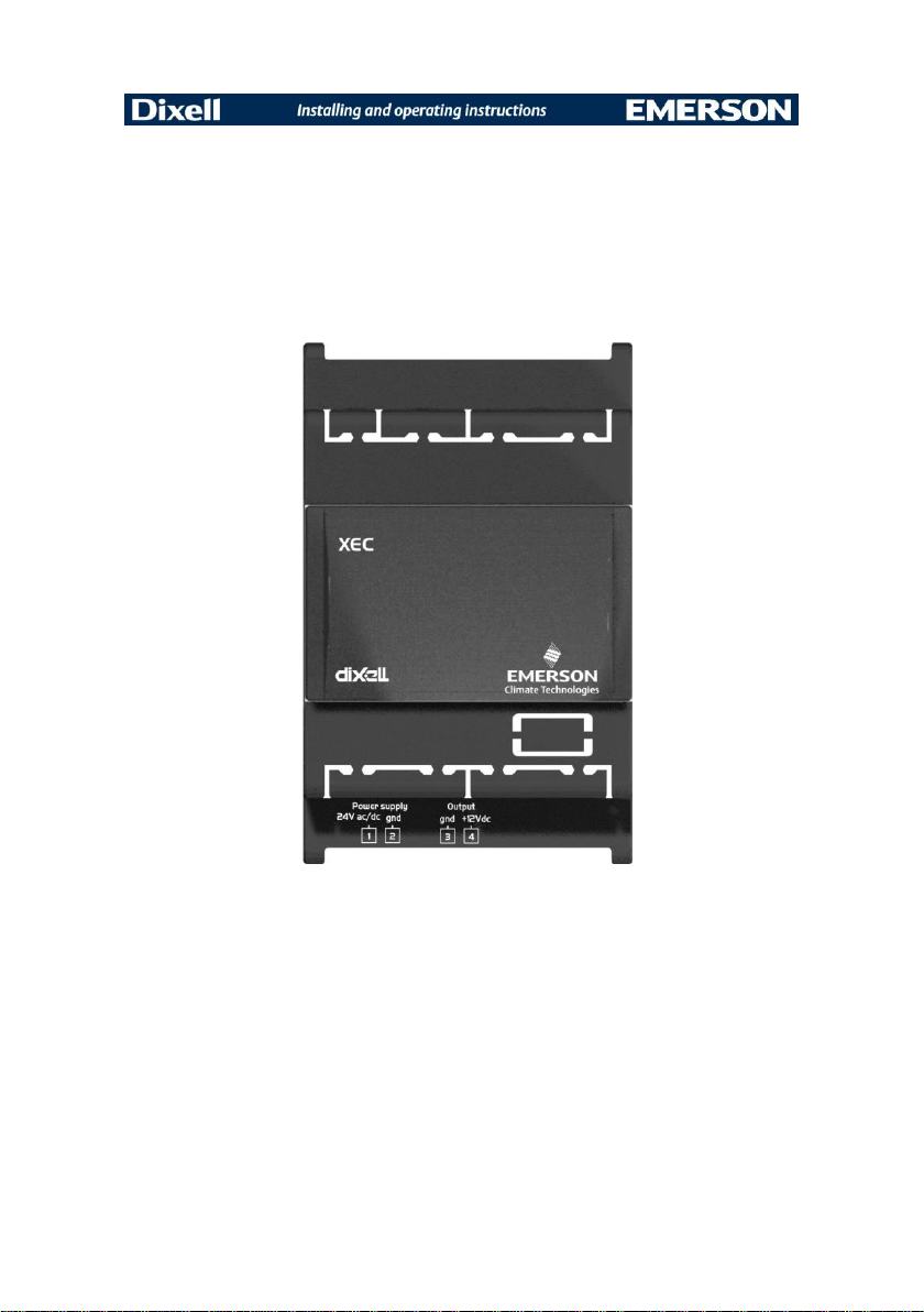
XEC supercap
(v. 1.0)
Page 2

Page 3

1. Installation notes
symbol alerts the user of important operating and
maintenance (assistance) instructions found in the documentation
attached to the device.
This manual forms part of the product and must always be kept
near the device for easy and quick reference. The device cannot be
used as a safety device. Verify the limits of application before using
the device.
XEC Supercap must be installed in environments that have the following
characteristics:
Environment temperature and humidity must be within the range
stated in this document
XEC Supercap should not be exposed to direct sunlight and
protected from water and high atmospheric humidity in order to
prevent condensation from forming
XEC Supercap must not be subjected to mechanical stress
(vibration and/or direct hits)
Sulfur, ammonia, smoke and salt can cause corrosion and oxidation
XEC Supercap must not be installed in environments containing
flammable or explosive gases
XEC Supercap must not be installed in dusty environments
XEC Supercap must not be installed near devices that can
generate electromagnetic interference
XEC Supercap module must be installed inside electrical panels;
pay attention to:
o
guarantee adequate distance between the module and
power electrical devices
o
ensure sufficient air circulation around the device
1592010460 XEC GB rel.1.0 26.01.2015 XEC 3/16
Page 4
Warning:
XEC Supercap has to be installed, operated and serviced only by
qualified personnel
do not disassemble, repair or modify this device
before removing XEC Supercap from the electrical panel, switch off
the electrical panel to discharge the capacitors (device connected
to XEC Supercap must remain connected to force closing
procedure of the valve). After switching off, wait at least 1 minute
before removing XEC Supercap.
No responsibility is assumed by Dixell S.r.l. in case of non-compliance with
the above recommendation.
1.1 General rules
XEC Supercap is designed to be used with Dixell products (XEV, IEV
and others); compatibility with Dixell devices has to be verified in the
user manual/technical sheet of the device connected to the XEC. In
case of dubt, please contact Dixell Service department.
Before connecting the device, verify that the power supply is compliant
with the rating.
Separate the power of the device from the rest of the electrical
devices connected inside the electrical panel; XEC Supercap
requires a dedicated transformer.
The secondary of the transformer must never be connected to the
ground.
The failure of the observance of this rule may result in damage to
the XEC Supercap and / or the connected device.
Dixell Srl reserves the right to modify this manual without prior notice.
The documentation can be downloaded from www.dixell.com even prior
to purchase.
Dixell Srl reserves the right to change the composition of its products,
even without notice, ensuring the same and unchanged functionality.
1592010460 XEC GB rel.1.0 26.01.2015 XEC 4/16
Page 5
1.2 Product disposal (WEEE)
With reference to Directive 2002/96/EC of the European Parliament and
of the Council of 27 January 2003 and to the relative national legislation,
please note that:
There lies the obligation not to dispose of electrical and electronic
waste as municipal waste but to separate the waste.
Public or private collection points must be used to dispose of the
goods in accordance with local laws. Furthermore, at the end of the
product's life, it is also possible to return this to the retailer when a
new purchase is made.
This equipment may contain hazardous substances. Improper use
or incorrect disposal can have adverse effects on human health
and the environment.
The symbol shown on the product or the package indicates that the
product has been placed on the market after 13 August 2005 and
must be disposed of as separated waste.
Should the product be disposed of incorrectly, sanctions may be
applied as stipulated in applicable local regulations regarding waste
disposal.
1592010460 XEC GB rel.1.0 26.01.2015 XEC 5/16
Page 6

2. Connections
Connector Pin
number
Description
Power input
1
24 Vac / Vdc (+)
2
24 Vac / Vdc (gnd)
Power output
3
gnd
4
+12Vdc
1592010460 XEC GB rel.1.0 26.01.2015 XEC 6/16
Page 7

3. Connection diagram
Connection diagram of XEC Supercap to XEV20D or IEV 22D driver to
control an electronic expansion valve.
XEC Supercap and XEV20D or IEV22D must be powered by two different
transformers; the failure of the observance of this rule may result in damage
to the XEC Supercap and / or the connected device.
Connection diagram of XEC Supercap to XEV20D or IEV24D driver to
control two electronic expansion valves.
XEC Supercap and XEV20D or IEV24D must be powered by two different
transformers; the failure of the observance of this rule may result in damage
to the XEC Supercap and / or the connected device.
If the XEV20D or IEV24D driver controls two expansion valves, two XEC
Supercap have to be used.
For both XEC Supercap:
respect the same power supply connection (terminal 1 of both XEC
Supercap has to be connected to the same pole of the transformer;
terminal 2 of both XEC Supercap has to be connected to the other
pole of the transformer)
terminal 3 (gnd) of both XEC Supercap has to be connected to the
“gnd” of the connected device; terminal 4 (+12V) of both XEC
Supercap has to be connected to the “In” of the connected device.
1592010460 XEC GB rel.1.0 26.01.2015 XEC 7/16
Page 8

Connection to XEV20D driver and one expansion valve:
1592010460 XEC GB rel.1.0 26.01.2015 XEC 8/16
Page 9

Connection to IEV22D driver and one expansion valve:
1592010460 XEC GB rel.1.0 26.01.2015 XEC 9/16
Page 10

Connection to XEV20D driver and two expansion valves:
1592010460 XEC GB rel.1.0 26.01.2015 XEC 10/16
Page 11

Connection to IEV24D driver and two expansion valves:
1592010460 XEC GB rel.1.0 26.01.2015 XEC 11/16
Page 12

Power supply:
24 Vac/dc+/-20%
Freq.: 50 / 60 Hz
Output voltage:
12 Vdc +15%÷-0%
Power consumption:
12VA
Max. output current:
1.2 A max.
Charging time:
1 minute
Max. current in charging
time:
350 mA
Input/output max. lenght:
50 cm.
Use AWG18 cables.
Max. number of valves
closure after a complete
charging time
1
Connectors:
Screw extractable connector (wire ≤
2.5mm2)
4. Electrical specification
1592010460 XEC GB rel.1.0 26.01.2015 XEC 12/16
Page 13

Assembly:
DIN rail mounting (EN 50022, DIN 43880)
Material:
ABS
Selfextinguishing
:
V0 (UL94)
Color:
Black
IP protection:
IP20
Product
certification:
Immunity for industrial environments
EN61000-6-2, EN61000-6-2/EC, EN61000-6-2/IS1
---------------------------------------------------------------------
---Emission standard for residential, commercial and
light-industrial environments
EN61000-6-3, EN61000-6-3/A1
Operating temperature:
-10°C ÷ 60°C
Storage temperature:
-20°C ÷ 70°C
Relative humidity:
20% ÷ 85% (not condensing)
5. Plastic case
6. Environmental conditions
1592010460 XEC GB rel.1.0 26.01.2015 XEC 13/16
Page 14

7. Dimensions
1592010460 XEC GB rel.1.0 26.01.2015 XEC 14/16
Page 15

Page 16

 Loading...