

Page 1
EXqERSON ANDTHE GCLEF LOGO ARE REGISTEREDTRADENARKS
OF PIERSON RADIO CORR. P/\RS PBZ\NX NEW JERSEYUSA
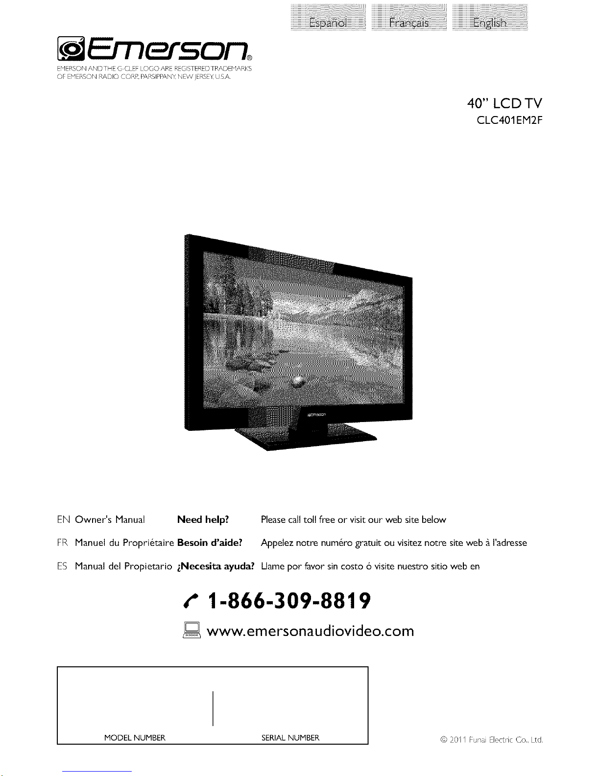
40" LCD TV
CLC401EM2F
EN Owner's Manual Need help? Please call toll free or visit our web site below
FR Manuel du Propri6taire Besoin d'aide? Appelez notre num6ro gratuit ou visitez notre site web _ I'adresse
ES Manual del Propietario zNecesita ayuda? Llame pot favor sin costo 6 visite nuestro sitio web en
t" 1-866-309-8819
ID www.emersonaudiovideo.com
MODEL NUMBER SERIAL NUMBER
© 20II Funa Electric Co., Ltd,
Page 2
2
WARNING: TO REDUCE THE RISKOF FIREOR ELECTRICSHOCK, DO NOT EXPOSETHIS
APPARATUS TO RAIN OR MOISTURE.
APPARATUS SHALL NOT BE EXPOSEDTO DRIPPING OR SPLASHING AND NO OBJECTS
FILLEDWITH LIQUIDS, SUCH AS VASES,SHALL BE PLACED ON THE APPARATUS.
CAUTION:
TO REDUCE THE RISK OF ELECTRIC SHOCK, DO
NOT RENOVE COVER (OR BACK}. NO USER
SERVICEABLE PARTS INSIDE. REFER SERVICING TO
QUALIF(ED SERVICE PERSONNEL.
]-he lightn ng flash with arrowhead symbol, withn
an equilateral triangle, is intended to alert the
user to the presence of uninsulated "dangerous
voltage" withn the apparatus's enclosure that may
be of suffic ent magnitude to const tute a risk of
electrc shock to persons.
The exclamation point wthn an equ lateral triangle s
intended to alert the user to the presence of mportarTL
operating and maintenance (servicing) instructions in
the literature accompanyng the apparatus.
The caut on marking is located on the rear or bottom of the cab net.
Important Safety Instructions
1. Read these inslructions. 10. Prolect the power cord fi_om being walked on or
2. Keep these inslrudions.
3. Heed all warnings.
4. Follow all inslructions. 11.
5. Do no1 use this apparstus near wstem:
6. Clean only with dry clolh, 12.
7. Do no1 block any ventilstion openin{_>s,Install in
accordance with the manufacturer's inslruclions,
8. Do nol inslall near any heat sources such as radislors,
heat regislers, sloves, or olher apparatus (including
amplifiers) thst produce heat.
9. Do not defeat the safety purpose of the polarized or 13.
grounding type plu{_>,A polarized plug has lwo blades
with one wider than the olhem:A {_>roundin{_>type plug 14.
has lwo blades and a third {_>rounding prong,The wide
blade or the third pron{_>are provided for your safety, If
the provided plu{_>does no1 fit into your outlet, consult
an eleclrician For replacement of the obsolete outlet.
pinched particularly st plugs, convenience receplacles,
and the point where they exit fi_om the apparstus.
Only use sttachments/accessories specified by the
manu facturel:
Use only with the cart, sland, tripod, bracket, or
table specified by the manufadureh or
sold with the apparatus.When a cart
is used, use caution when moving the
cart/apparstus combinstion to avoid
injury fi_om tip ovel:
Unplug this apparatus during lightning storms or when
unused for long periods of time.
Refer all servicing to qualified service personnel.
Servicing is required when the apparstus has been
damaged in any way, such as powel_supply cord or
plug is damaged, liquid has been spilled or objects
have Fallen into the apparstus, the apparatus has
been exposed to rain or moislure, does nol operate
normally, or has been dropped,
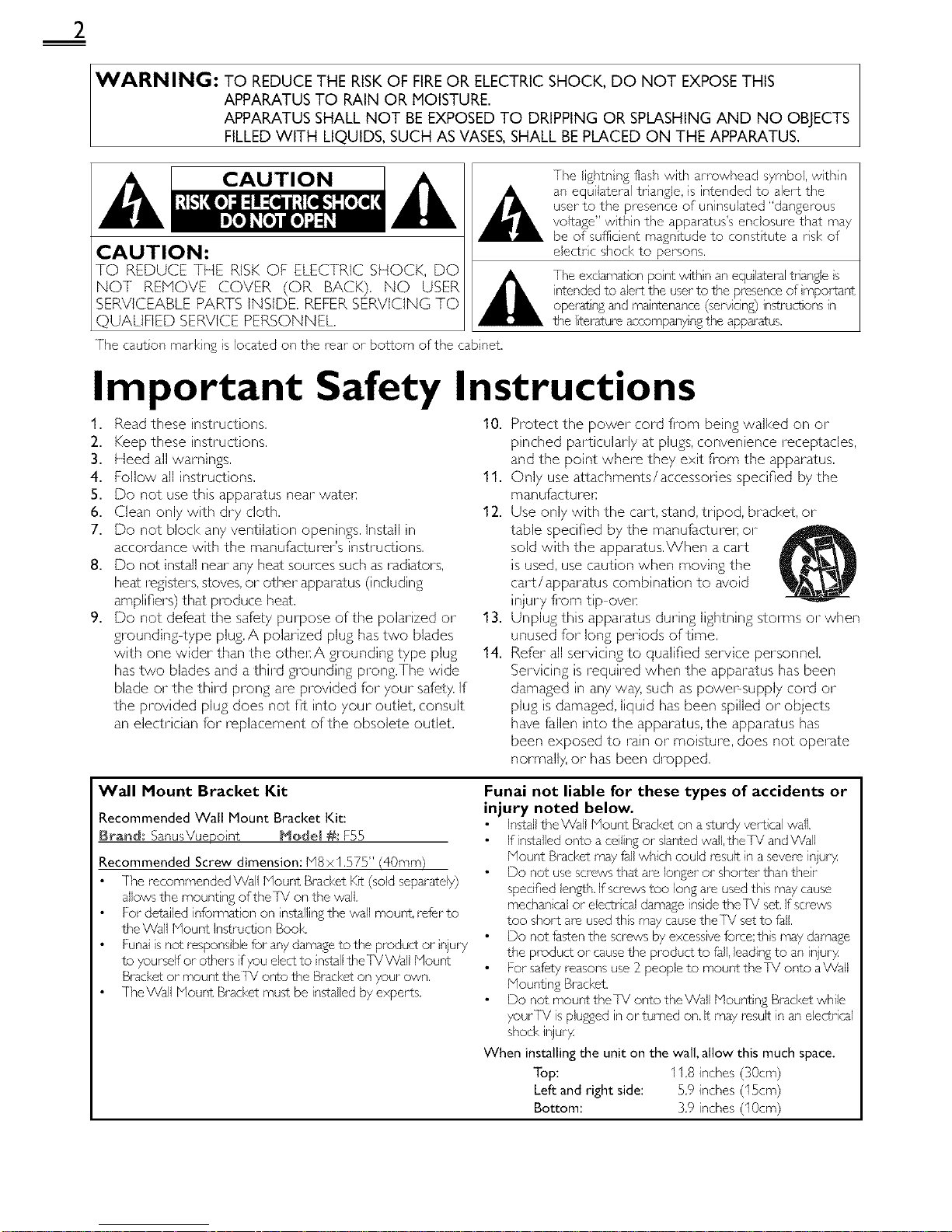
Wall Mount Bracket Kit
Recommended Wall Mount Bracket Kit:
Brand; SanusVuepo nt Mode( #s F55
Recommended Screw dimension: M8 x 1.575" (40ram}
The recommended Wall Mount Brad<et KR (sold separately)
allows the mounting ofthe]V on the wall.
For detM(ed information on nstalling the wall mount, refer to
the Wall Mount Instruction Book
Funal is not respons ble for any damage to the product or njury
to yourself or others if you elect to nstall the]VWaU Mount
Bracket or mount the TX/OrTLOthe Bracket on your own.
TheWall blount Bracket must be installed by experts.
Funai not liable for these types of accidents or
injury noted below.
Install theWall Nount Bracket on a sturdy vertical wall.
If installed onto aceiling or slanted wall, the]V and Wall
Mount Brad<et may fall which could lesu(t in a severe injuo4
Do not use screws that are longer or shorter than their
specified len2_¢h.)f screws too long are used this may cause
mechanical or electr cal damage inside the]X! set. If sa ews
too short are used ths may cause the TX/set to fall.
Do not fasten the saews by excessive foree;th s may damage
the product or cause the product to fall, leading to an injuo4
For safety reasons use 3_people to mount theTX/onto aVVaU
Mount ng Brad<et.
Do not mount theIV onto the Wall bqountin;_ Brad<et while
your/X/is plumed in or turned on. It may lesu(t in an electrical
shod< injuo4
When installing the unit on the wall, allow this much space.
Top: 11.8 inches (30cm)
Left and right side: 5.9 inches (15cm)
Bottom: 3,9 inches (10cm)
Page 3
FCC WARNING
This apparatus may generate or use radio frequency energy. Changes or modifications to this apparatus may cause harmful interference
unless the modifications are expressly approved in the manual. The user could lose the authority to operate this apparatus if an
unauthorized change or modification is made.
RADIO-TV INTERFERENCE
This apparatus has been tested and found to comply with the limits for a Class B digital device, pursuant to Part 15 of the FCC Rules.
These limits are designed to provide reasonable protection against harmful interference in a residential installation. This apparatus
generates, uses, and can radiate radio frequency energy and, if not installed and used in accordance with the instructions, may cause
harmful interference to radio communications. However, there is no guarantee that interference will not occur in a particular installation.
If this apparatus does cause harmful interference to radio or television reception, which can be determined by turning the apparatus off
and on, the user is encouraged to try to correct the interference by one or more of the following measures:
1) Reorient or relocate the receiving antenna.
2) Increase the separation between the apparatus and receiver.
3) Connect the apparatus into an outlet on a circuit different from that to which the receiver is connected.
4) Consult the dealer or an experienced radio/TV technician for help.
DECLARATION OF CONFORMITY
Trade Name: DY_erson Responsible Party: FUNAI C©RP©P_TI©N, Ine
Model: CLC401 EH2F Address: 19900 Van Ness Avenue. Torrance, CA 90501 US.A.
Telephone Number: 1-866-309-8819
This Class B digital apparatus complies with Canadian ICES-003. StandardTelevision ReceivingApparatus, Canada BETS.7/NTMR.7
CAUTION: Danger of explosion if battery is incorrectly replaced. Replace only with the same or equivalent type.
WARNING : Batteries (battery pack or battery installed) shall not be exposed to excessive heat such as sunshine, fire or the like.
Disconnect the mains plug to shut off when find trouble or not in use.The mains plug shall remain readily operable.
This apparatus should not be placed in a built-in installation such as a bookcase or rack unless proper ventilation is provided.
Hake sure to leave a space of 4 inches (10cm) or more around this apparatus.
WARNING: To prevent injury, this apparatus must be securely attached to the wall in accordance with the instructions.
Do not place the unit on the furniture that is capable of being tilted by a child and an adult leaning, pulling, standing or
climbing on it. A falling unit can cause serious injury or even death.
(_) I._AMP IN LCD CONTAINS MERCURY, DISPOSEACCORDINGTO LOCAL, STATE OR FEDERAL LAW.
• The American Academy of Pediatrics discourages television
viewing for children younger than two years of age.
NOTE ABOUT RECYCLING
• Ths unit's pdckdging maters am recyclable r,d
can be reused, Please dispose of any materia s n
accordar, ce with your Iota recyc r,g i-egu at ons,
Batteres shoud never be thrown away or nciperated
but disposed of n accordance with your Iota
regu ations concern ng chemical wages.
• For product recycling informat on, pease vsit
www.emersonaudiovideo.com
WHEN CARRYINGTHIS UNIT k i_
• At east 2 peope dre mqumd wl,en
carry ng this unit. I
• Make sure to hold the upper and bottom
frames of the unit firmy as u£rated,
TO AVOID THE HAZARDS OF
ELECTRICAL SHOCK AND FIRE "
• Do pot hndle the AC power cord with wet I'ar'ds.
• Do not pul on the AC power cold when disconnect ng it flora an
AC outlet. Grasp it by the pug.
• Do not put your fingers or objects into the unit.
LOCATION AND HANDLING
• Do not nstall the unit n direct sunlight or in a pace subject to dust
or strong vibl _tiorl.
• 2wod a place wth drastic temperatuJe changes.
• Ir,stal the unit n a horzontal and stable posit on. Do pot place anytlmg
direct y on top or bottom of the unit Depend ng on your ext_,rna
devices,noise or d sturbance o_the p cture and/or sound may be
gene/ste,d fthe unit is placed too close to them, It,this case, pease
ensure enough space between the ext_,rna devces and the unit,
• Depend ng on the envirorlmerlt, the terr'pe/aturo of this un t mdy
incroase s gbt y.This isnot a rna fur,or on.
• Be sure to unpug the AC power cord fl_m the AC outer before
moving or carry ng the unit.
Trademark Information
Hi=l1111 °
HDN], the HDNI Logo, arid High Definlt on Nut media Inter#see are
trademarks or i-eglstered trademad<s of HDNI Lcens ng LLC in the
United States and other countres.
ITI DOLBY
DIGITAL]
Nanuf_£tured under Itense from Dolby Laborator es. Dob 7 dnd the
double_D symbol am trademad<s of Doby Laboratories.
Page 4

4
Congratulations on your purchase! As you enjoy your new product, please
keep these safety tips in mind:
THE ISSUE
• [he t-ometi_ealerenle a nmentexperence s a growh'g rend and large
flat panel displays are popular purchases However, flal panel displays
are not always suppored on the proper stonds or inslalled accord ng to the
manufacture's recomrqendalions
• Flat panel displays thatare inappropriately stuatedon dressers,bookcases,
shelves,desks, speakers,chestsor cartsmay fall over and cause injury
THIS MANUFACTURER CARES!
• Tt'e consumerelectroncs induslry iscommitted to r,,aking homeenterta nn"ent
enjoyable and safe
TUNE INTO SAFETY
• One sze does NOT f all Follow the r_anufacturer'secommendations
for the safe rTstallotionar'd useof your flat panel display
• Carefully read ar,d ur,derstar,d all er,closed instructionsfor arooer useof
this product
• Don't allow children to clmb on or play with furnitJre and telev sion sets
• Don't place flat panel displays on turntare thatcan easily be used as steps,
such as a chest of drawers
• Rememberthai children can become excited while watching a program,
especially on a "larger tha_"life" flal panel display Care shouldbe iaken to
place or install_hedisplay wf'e_e it cannol be pushed, pulled over,
or knockeddowr"
• Care should be taken to routeall cords and cables cant'eared to theflat
panel display so thatthey cannot be pulled or grabbed by curiouschildren
WALL MOUNTING: IFYOUDECIDETOWALLMOUNT
YOURFLATPANELDISPLAY,ALWAYS:
• Use a mountthat has been recommended by he display _anufacturer
and/or Ised by an ndepe_'dent laboratory (suchas UI, CSA, Erl)
• Follovvall inslructionssupplied by thedisplay and wall mount manufacturers
• If you haveany doubtsabou your ability 1osafely installyour flal panel
d splay, contact your retailer about professonal installaton
• Make sure thatthe wall where you are mounting thedisplay s appropriate
Some wall mountsare nat designed to be mountedto walls with steel
studsor old cnder block construction If you are unsure,contact a
professional nstaller
• A '_qnimumof lwo people arerequi ed for installaton Flal panel displays
can be heavy
www.CE.org/safety
Page 5
INTRODUCTION Features
Contents
Important Safety Instruct ons
Pademark Information
Child Saf_,ty
INTRODUCTION
Featul es
Supplied Accessor es
Symbols Used in this Manual
Attachin S the Base
Mounting the Unit on Your Furniture
Remote Control Function
Instalfin8 the Batter es
Contro Panel
lbrrnina s
(-abe Manaaement
2
3
4
6
6
6
6
7
7
8
9
9
PREPARATION
Antenna Cor, nection I 0
Connection to Cable Receiver or Satellite Box I0
Pu£ In the AC Power Cord I0
Initial Setup 11
WATCHING TV
Swtchin 8 Each Input Mode I2
Sleep Nmer I2
Sound Functions I2
Freeze Mode 13
IV Screen Dispby Mode I3
Channel Select on 13
TV Screen Information 14
ECO I4
USING FUNCTIONS
Pcturo 16
Sound 16
Setup 1-7
Featul es 18
Lanauaae 23
USB 14
CONNECTING DEVICES
External Dr, vice Connect on 15
USEFULTIPS
FAQ 18
oub eshoot n8 Gude 28
INFORMATION
Glossary 30
Maintenance 30
General Specifications 3I
Electrical Specification 3I
Other Specifications 3I
Limited W_n-anty 33
DTV/TV/CATV
You can use your remote contro to seect channels whch are
broadcast in d£iM format and convent ona anao 8 format, Also,
cabe subscribers can access thor cableTV channe s,
Information Display (/_[SC only)
You can display the trio, contents and other nformation of the
current DTV plsgram on theTV s@een,
Autoprogram
Ntis unt automat ca y scans and memor zes char, nels _Vd abe it,
your area, e m nat n8 d fqcut setup pl_cedures,
Child Lock
/
i¸i¸8
3>
{5
This Mature allows you to block ch Idren's access to inappropr ate ]
progrdms,
Closed Caption Decoder
Built ncosed caption decoder disp ays text fur closed capt on
supported proarams,
i
MTS / SAP Tuner
Audo can be selected fl-om the remote contro,
Auto Standby
If there s no input sanl and no operat on for I5 minutes, the
unit will go into standby mode automatically.
Sleep Timer
You can set the unit to go into standby mode after a specific
i
amount of time,
Choices for On-screen Language
Select your on saeen nSudse:
En8 sh, Span sh or French,
Stereo Sound Function
PLL Frequency Synthesized Tuning
Prov des flee and easy channe se ection and ets you tune
direct y to any channel usn£ the number and dec real point '%"
butt ....... the remot ...... tro.
Various Adjustment for Picture and Sound
Customi ...... 8e quaty suitab e for y............. d sets your
sound prefi, rence,
fun-Link via HDMI Link
(HDll Cable not Included)
fun Link alows your other HDMI link dev ces to be contro ed by
the HDMI cable connected to yourTV.
HDMI Input
HDMI-DVI Input
When usin 8 HDMI I Input you can enjoy this unt as d PC
morutor f your PC has a DVI output terminal,
ComponentVideo Input
S-Video Input
AV Input
USB Terminal
The picture @PEG)dnd vdr, o (Mot or1jPEG) files stored on d
USB storaae devce can be payed back on this unit,
Digital Audio Output
Analog Audio Output
© 2011 Funa Electric Co., Ltd,
All rghts reserved, No part o_this manua may be reproduced, copied, transmkted, disseminated, transcribed, downloaded or stored in any storaso
medium, n any form or for any purpose without the express pnor wr tt_,n consent of Funa},Fucttlermom, any unauthorizc,d commerc al distlibution of
ths manu or any revison he/eto s stricty plx)hibited.
Information in this document s subject to chanse without notice. Funai reserves the risht to chanse the content heron w thout the oblisat on to notfy
any person or o%anization of such chanses,
F'UNAIwith the _'_ desisn s a i e£istered trademark of Funs Eectr c Co., Ltd, and may not be used n any way w thout the express wr tten consent
o_ Funak All other trademarks used herr, n roman the exclusive property of thor respect ve owners, Noth ng contained n ths manua shoud be
construed as £1_nt ns, by implication or otherw so, any license or r£ht to use any of the trademarks displayed herein. Misuse of any trademarks or
any other content inthis manua is strict y prohibited, Funai shall a£sressive y enforce ts nte ectua property r£hts to the fullest extent o+the law.
Page 6
6
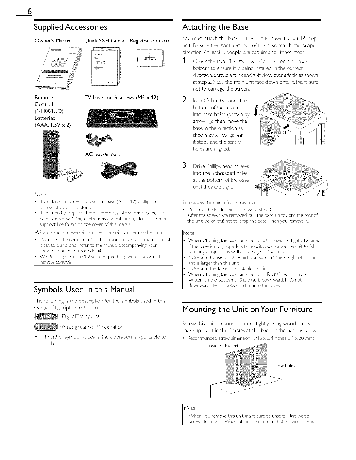
Supplied Accessories
Owner's Manual Quick Start Guide Registration card
Remote TV base and 6 screws (M5 x 12)
Control
(NH001UD)
Batteries
(AAA, 1.5V x 2)
AC power cord
No_e
If you lose the screws, please purchase (bi5 x 12) PhIlips head
screws st your oca[ £ore,
If you need to replace these accessories, please rek, r to the part
name or No. with the illuss ations and call our toll flee customer
support line found on the cowr of this manual,
V_el sr_;_ ;_ur/vers;_ rer/o e cos r_; o op rate ths _s
Make sure the component code on your universa iemote control
is set to our brand, Ref_,r to the manual accompanying your
romote control for moro dotaiB.
We, do not guarantee 100% interoperabil ty with all universal
romote controls,
Symbols Used in this Manual
The f0ilowing s the descr ption for the symbols used n ths
manual. Description refers to:
: D gitallV operat on
:Analog/Cable rv operation
If neither symbol appears, the operation s applicable to
both.
Attaching the Base
You must attach the base to the unt to have t as a table top
unit. Be sure the front and rear of the base match the proper
direction, At least 2_people are requ red for these steps,
1 Check the text "FRONT" w_th "an ow" on the Base's
bottom to ensure t is being installed n the correct
direct on. Spread athck and soft cloth over a table as shown
at step 2. Place the man unit face down onto _t.Make sure
not to damage the screen.
2
Insert 2 hooks under the
bottom of the main unt
into base holes (shown by __C'_ "';
arrow ,_},),then move the
base n the d rect on as
shown by arrow ,12)until
it stops and the screw
holes are algned.
3 Drve Philips head screws
into the 6 threaded holes
at the bottom of the base
until they are tght.
]b _ ' nova the base fron ds _r/t
• Unscrew the Phillips head screws in step 3,
After the screws are removed, pull the base up toward the mar of
the unit, Be ca1_,fu not to drop the base when you remove It,
Notx'
When attaching the base, ensure that a screws are tightly fdstened,
If the base is not propedy attached, it could cause the unt to fJII,
result ng n njuries as well as damage to the unt.
blake sure to use a tabe whch can support the weight ofths unt
and s arger than this unt,
Make sum the table s n a stable ocation,
When attachin£ the base, ensure that"FRONT" wth "an-ow"
written on the bottom of the base is downwald. If t's not
downward, the _ hooks don't fit into the base,
Mounting the Unit onYour Furniture
Screw this unt on your furnture t ghtly usng wood screws
(not supplied) in the 2_holes atthe back of the base as shown.
• Recommended screw dimens on :3/16 x 3/4 riches(5,1 x _0 ram)
rear of this unit
screw holes
Page 7

Remote Control Function
I SOURCE ,,,,,_p.12
11 2 SLEEP ,,,,,_p.12
3 BACK ,,,,,_1),14
12
13 4 ilVl_lll_(cursor) Hill 1).11
5 MENU ,,,,,_1).15
14
6 OK ,,,,,_1).11
7 VOL A/V IlIII_1).12
8 MUTE D_ llIII_"1).12
15
9 Number buttons ,,,,l1).13
16
• (dot)
17
Press to shft the subchannel from the main channel.
10 PREVCH ,,l 1).13
Press to return to previously vewed channel.
11 d) (power) ,,_ I).11
Press to turn the unit on and go into standb 7 mode.
[o completely turn offthe unit, you must unplug the AC
power cord.
12 FORMAT I_ ,,_ 1).13
Press to select aspect ratio available for theTV screen.
13 FREEZE ,,_ p.13
Press to freeze screen image.
14 ECO J ,,_ p.14
Press to reduce power consumption.
15 INFO ,,l p.14
16 SAP iliii_.1).12
17 CH ,&IV IlllI_ 1).13
Installing the Batteries
Install the batteries (AAA, 1.5V x 2_) matching the polar ty
indicated inside battery compartment of the remote control.
Be sure to follow the correct pol rty as nd cared n the battery
compartment, Reversed batteries ma7 cause dama£e to the
device,
Do not mix d ff_w, nt types of batteries together (e.g, Akane and
Carbon Z nc, or rechargeable batteries like r,i cad, nmh, etc) or
od batteries with fi_esh ones,
If the devce is not to be used for }0% period of time, remove
the batter es to prevent damase or njury flsm poss hie battery
eaka£e.
Do not try to rochar£e batter es;they can ovo/heat and rupture,
/
::iiiil
!iq
¸¸{}i
!}
(3'
. IC
ii,iiii!
4
ii_,!:!{i
Page 8
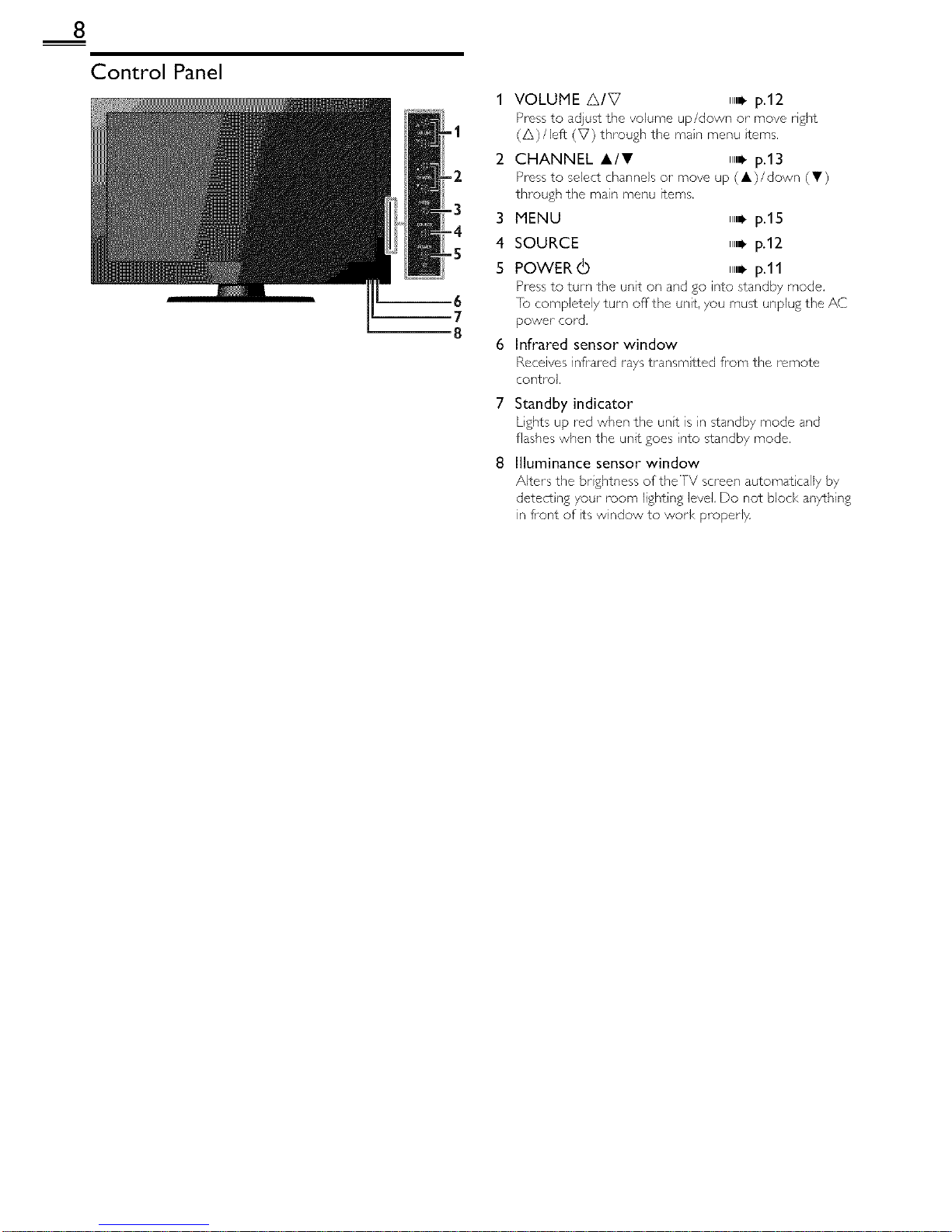
8
Control Panel
-1
2
-2
-3
3
-4
-5 4
5
m7
8
6
VOLUME A/V ,,,_p.12
Press to adjust the volume up/down or move right
(A)/left (V) through the main menu terns.
CHANNEL A/I!' ,,_ p.13
Press to select channels or move up (A)/down (V)
through the main menu items.
MENU ,,i. p.15
SOURCE ,,i. p.12
POWER (b ,,i. p.11
Press to turn the unit on and go into standby mode.
[o completely turn offthe unit, 7ou must unplug the AC
power cord.
Infrared sensor window
Receives inflated rays transmtted from the remote
control.
7 Standby indicator
Lights up red when the unt is n standby mode and
flashes when the unit goes nto standby mode.
8 Illuminance sensor window
Alters the br ghtness of the TV screen automat caliy by
detect ng your room lighting level Do not block anything
in fiont of ts window to work proper1}4
Page 9
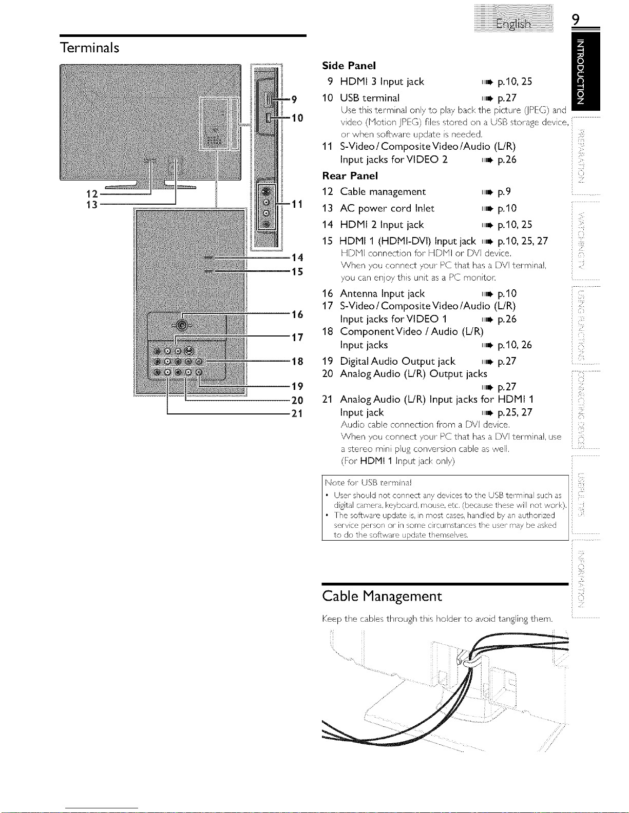
Terminals
12--
13
14
15
Side Panel /
9 HDMI 3 Input jack ,,,,_ p.10, 25
10 USB terminal ll,_ p.27
Use this terminal only to play back the picture (JPEG)and
video (Notion ]PEG) flies stored on a USB storage device.
or when software update s needed.
11 S-Video / Composite Video/Audio (L/R)
Input jacks forVlDEO 2 ll,_ p.26
Rear Panel
12
13
14
15
16
17
18
19
20
21
Cable management _,_ p.9
AC power cord Inlet _,_ p.10
HDMI 2 Input jack ll,_ p.10, 25
HDMI 1 (HDMI-DVI) Input jack ll,_ p.10, 25, 27
HDNI connection for HDNI or DVI devce.
When you connect your PC that has a DVI terminal.
you canenjoy this unt as a PC montor:
Antenna Input jack ll,_ ).10
S-Video / Composite Video/Audio (L/R)
Input jacks forVtDEO 1 ll,i- ).26
ComponentVideo / Audio (dR)
Input jacks ll,_ ).10, 26
Digital Audio Output jack ll,_ ).27
AnalogAudio (UR) Output jacks
_,i- ).27
AnalogAudio (L/R) Input jacks for HDMI 1
Input jack ll,_ p.25, 27
Audo cable connect on from a DVI devce.
Z
ZfJ
ii _7_i""
'_i;__
i((
When you connect your PC that has a DV] terminal, use
a stereo rain plug convers on cable as well.
(For HDMt 1 Input ]acl< only)
Cable Management
Keep the cables through ths holder to avod tangling them.
Page 10
10
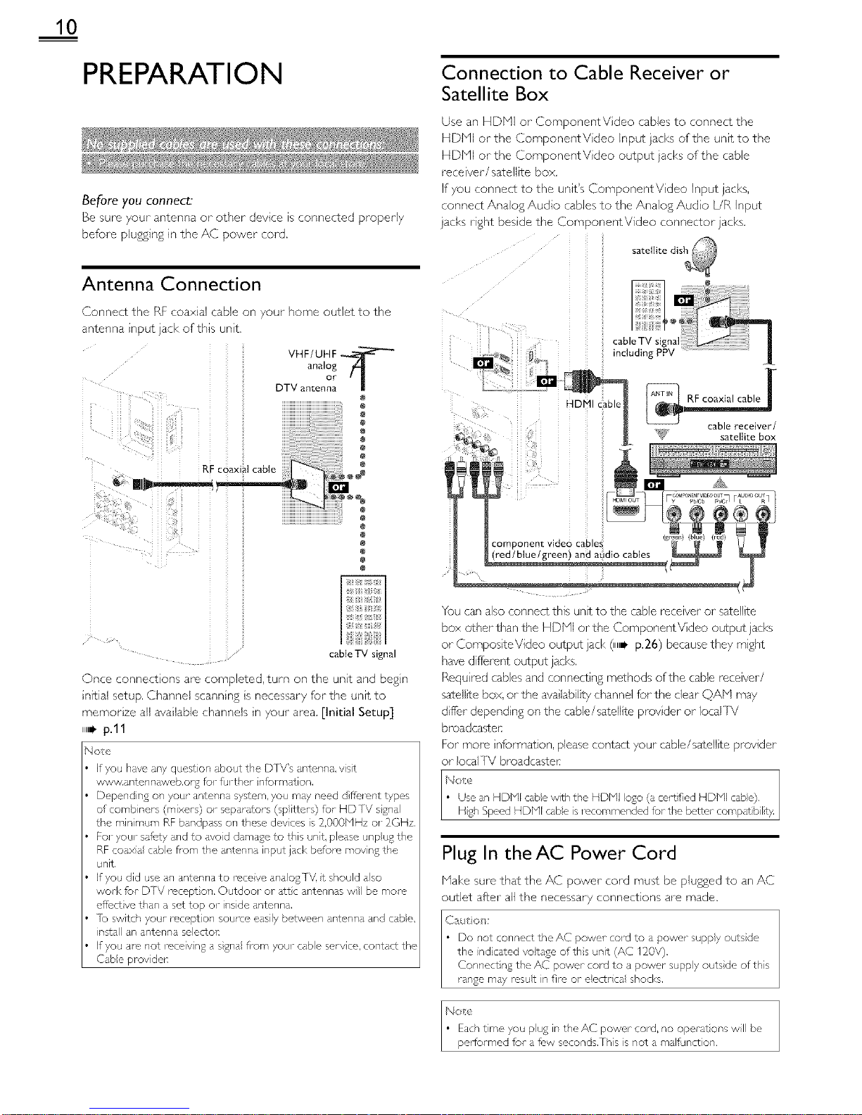
PREPARATION
Before you connect:
Be sure your antenna or other device s connected properly
before plu,_sng In the h,C _ower cote1
Antenna Connection
_onnect the Rt coaxlai .able o _our home outlet to the
_ntenna input jack of this unit
VHF/UHF
analog
DTV anten °r " !
e
@
RF coaxial cable
o!o2
cable TV signal
Once conne ]lO_/S are cot_/oletec1 turn on the unit and begin
inlt al setup. Channel scanning is necessary for the unit to
memorize all available channels in your area. [Initial Setup]
,_ p.ll
No_,
If you have any quest on about the DTV's antenna, vsit
www.antennsweb.o% for further nformation.
Depending on your antenna system, you ms}, need d tie, ant types
of comb nets (mixers) or separators (sp itters) fur HDTV signa
the rain mum RF bandpass or, these devces is 2,000MHz or 2GHz.
FoJ-you_-safety nd to dvod damage to this unit, please unpu£ the
RF coaxa cable flsm the antenna input jack before movn£ the
unit.
If you did use an antenna to race ve ana ogTV. t should aso
wod< for DTV receptor,. Outdoor or sttc ar,tennas w be more,
effect ve than a set top or inside antenna.
lb switch your mcept on source easily between antenna and cabe,
nstall an antenr, a selectoE
If you a_c,not roceiv n£ a sgna fl_m your cable serv ca, contact the
Cabe prov de_:
Connection to Cable Receiver or
Satellite Box
Use an HDFql or ComponentV deo cables to connect the
HDHI or the ComponentV deo input jacks of the unit to the
HDHI or the ComponentV deo output jacks of the cable
race ver/satellite box.
if you connect to the unit's ComponentVideo input jacks,
connect Analog Audio cables to the Analog Audo [JR input
jacks right besde the ComponentVideo connector jacks.
:: .... Ilite dis_
ii i
cab,oTV J _
including PPV
I'gll _!i ii ii @_ i i
|
_: _ ,,,,_ can ..... iver/
e_,_ ! _. sate,_tebox
i o:ee
; (red/blue/green) and aLidio cables
You can also connect this unit to the cable receiver or satellte
box other than the HDHI orthe ComponentVideo output jacks
or CompositeVideo output jack (,,_ p.26) because they mght
have different output jacks.
Requ red cables and connecting methods of the cable receiver/
satellite box, or the ava lability channel for the dear QAF'I may
dffer depend ng on the cable/satellite prov der or local IV
broadcas_Ler:
For more nformation, please contact your cable/satellite provider
or local TV broadcaste_
h4o_e
• Use an HDMI cabe with the HDMI ogo (a certfied HDMI cab@
H£h Speed HDbll cabe s iscommended for the better compat bil_t}4
Plug In theAC Power Cord
Hake sure that the AC power cord must be plugged to an AC
outlet after aJl the necessary connections are made.
C;_ut o/:
Do not connect the AC power co_x)to a powor suppy outs de
the nd cared vo}tage ofths unit (AC 120V).
Connect ng the AC power cord to a power suppy outs de of this
range mdy re,sut in fire or eectr ca shocks.
Noe
Each tree you plug it, the AC power cord, no operat ons wll be
peHormed for a f_,w seconds.This is not a malfunct on,
Page 11

11
'4 Use <1/1_ to select the desired Iocaton setting, then press
OK.
Initial Setup
This section will guide you through the unit's nitial setting
which ncludes selecting a language for your on screen menu
and autoprogram, which automat tally scans and memor zes
v ewabJe channels.
Before you begin:
Hake sure the unt is connected to antenna or cable.
1 After making all the necessary connect ons,
press _ to turn on the unit.
• It mat take a few moments to turn on the unt for the
first time.
• [initial Setup] menu appears automatcally after the
unt is turned on.
2 Use A/V to select the on screen language from the
choices (Engl sh / Espa_ol/Franca s) on the right sde of the
[V screen, then press OK.
3 Use A/V to select [Antenna] forTV channels or [Cable]
for C/Y[V channels, then press OK.
• [Autoprogram] will begin.
Select [Retail] s_tore,the unit will be set up with
predefined setting for retail d splays.
Select [Home], the unit s set to maxmze the energy
effic ency for home setting and t can be adjusted
through a choice of picture and sound quality accord ng
to your preference. Use this setting to remove the
E St cker fvis ble from the displa 7 ,,,,, p.23
When the ntial setup s completed.the lowest
memorized channel with the confirmation message of '
the location setting will be displayed on the]V screen.
You must set [Home] in step 4. Otherwise, [Picture]
and [Sound] settings you adjusted will not be
memorized after the unt goes into standby mode.
No#}
If you are, not leceiv ng a sgnal fl_m your cable serv ce. contact
the Cabe prov det:
If you Dess _ or MENU durng autoplogram, ths setup of TV
channels w be cance}ed.
The init al autoprogl m function can be executed for ether
[Antenna] or [Cable] ony once.When you change the
connect on (Antenn / Cab e). set [Autoprogram] agan. ,,_- p.17
If them is no signa input fi-om the antenna terminal and no
ope/at on for several seconds after you turn or, the unit. he pful
hints appears. Folow the instruct ons listed on theTV screen.
After an initial setup is completed...
• If you want to scan the channels automatically again.
[Autoprogram] lllil, p.17
• You can add the desired cable and analog channels
unmemorized b 7 autoprogram.
[Add Channels] _,_ p.18
• If you want to change to another language.
[Language] IlllI_ p.23
• If you want to change the location setting.
[Location] IlllI_ p.23
Page 12

12
WATCHING TV
Switching EachInput Mode __a__ y_wi{_hw_hth_remo_€o,]_i_o_
between TV (ATSC or- NTSC) and external devices when they are connected t0 the, unit
Bress SOURCE or CH A repeatedly fo cycle through the nput modes,
• e.g,)
DTWTV channel (or PC Input)
• P_-ess n£ CH V _c/erses me a recuc n otthe _su_ moac, s
Sleep Timer
_an SeT_ne UnT _C _O Irl_Os_anoc mode after an _ncr_rnenta E,nod of tree
Press SLEEP repeatea y _o cnango mc amount ottme qcreases
me _lme D 30 Is] nut -s LIDto 20 minutes
Sound Functions describe now _o cnange me aua o or me aua,o angua£e a<
/e as zne vo ume
.r
usc VOL A/V to ad ]s_ me voumn
De q SDaveo fop a t(,w seconds when adNs_ ng me volume
_Mode
Press MUTE _ to turn offthe sound tem
/ed for a fi,w secon@
£a n or VOL A/V to recover me or £n_
Audio Mode
• [Other] s (3soavea wnen me at ale _an£uagecar qo_ue
_CqLl_Fea,or_ne ac 7ulreg lansua_es aFeo_ner _nan In Z sh
Ssan sh or French
Press SAP to d so av me current _ se ectea aua,o moae
vn e rec_ _S an MTS DFoa(]casL DFeSS reDea_eo v _o CyCle _nPDL[_r
_no ava_aD_c auq_o cnanne
e.g.) vvr/en al aud o are avallaD c
Page 13

13
Freeze Mode c_n Uec,ze the mage shown on the] V screen for 5 m nu,es,
Press FREEZE to trceze the ,_la£e.
• lhe sound ou,Du, wl no, De DBUSpO.
c -_nce freeze mode Dress any E_RTORSeXCODt O
TV Screen Display Mode
5 tVDeS Of d SPar rnoaes can De SE'ec_c,a wnen ,ne Droaqcas_ 12 s,a_ oil m sena n£ 6:9 or 4:3 video • gna,And 3 types of dsp a
moaes can be selected for PC _npu_ s gna
Press FORMAT I_ reDeatedl to swtch theTV aseec_ ra_c
For 16:9 video signal
Normal 4:3 Movie expand
Unsc_Ied Wide Zoom
• [Unscaled] wil be d spayed on when the, HDNI vdeo st /a s 1080
or 1080D
For 4".3 video signal
Normal 16:9 Movie exoand
Wide Zoom
Normal d SDavs a I @9 p cture at its ori£ nal szo
4:3 d sDavs a I6:9 aLcture at a 4:3 sze: _ne D[c_ure
s snorteneo nonzon_ v. Sldcbars aDDear on t o,n
cages of the screer
Movie expand dlsp ays a 16:9 p c_ure _na_ s
vertica y stretched to fi the ! :rec / hLsonly crops
out the ted of the Dcture
Wide displays a qorz )nTauv s_re_cneo DeLL _e.] hs
cross out the left and ri£n_ sLaes of the ]Lc_ure
Unsealed d_sDlavs a D C_Ure _n is Or B qa_ sze
Normal d splays a 4:3 p cture at ts org na_ szr
g debars aDDear on DO,n ea_ -s of the street
1 6:9 disD avs a 4:3 D c_ur-e g, a 16:9 size [nr, D c_urc
s s,re_cnea norzon_s to fi[ tile street
Movie expand d SDaVS a 4:3 3tcture at a 16:9 stzc
the p C_UFQ S stre_cne(] more ver_ ca W a_ _ne ted of
_he screen.Th s croms out the to_ of the D CLUFO
Zoom a _Davs • _:3 D c_ure a_ a 6:9 szc a, _,s
rnax mum size _na_ m more vc -sca_ v stretcnea _o
_1 the screen,] his CrODS OU_ The _OD and bottom of
the D C_LF'O
Wide disD avs _ne D CLUrO w_n I,s center a_,ne
on£ hal s ze ana the c ]£es s_re_cnea nor zonta / _c
_" the screer
For PC input signal through _ Input mode
Normal | Full Unsealed 1
Normal d SPAYSa ores 3rt ona_e v s,re_cnea
Dcture. Sidebars appear on eo_n cages olthe screen
Full aisplays a plc[ure tlqa_ is s_re_cr]eo ou, c •
DrODOll'on hoRzonta to fi Ithe screen
Unsealed disD avs a Dc_ure in [s org hal szo
Channel Selection
Seect channe s Dy using CH A/• or the Number buttons
• fo seect the memor zed channcs, use, CH &/• or the Number buttons.
• ]o seec_ ,nr, nommc _or zeo cr _r qe s. use the Number buttons
To use the Number buttons
'A/her sere€ling ol_ channel I1
Be sure to Dress, before entenn£ me SdDcnanne_ numoe
Press PREV CH to return to the 9rewous> _ewea cnanne
- VVhe_ selecting cable or analog cnanne
• ]No Signal] v dDDCar on the screen dT_er The SuDcn4pno Droaatdst _s oveK
• [Audio only program] messd_e w appodl on the]V screen, when you rece ve ony sound s£na.
Page 14

14
TV Screen Information
You can d splaythe currently selected channel or other
nformation such as the audio mode on the TV screen.
In the digital mode. the detailed broadcast ng nformat on
for the current offthe air channel such as program ttle and
program guides are displayed.
1 PressINFO.
1 2
-9
-10
ECO
You can turn on ECO Node to conserve poweK
Press ECOJ once to turn on ECO Node and reduce
power consumption.
Press ECOJ again to turn offECO Node.
),4o e
• You must set [Home] in [Location], ,,B p,23
Otherwise, the sett ngs you sdjusted will not be saved when the
unit goes into standby mode,
1 programtde
2 program guide
(]he program guide added to broadcasting
information is d spla/ed to a max mum of 4 lines.)
3 broadcast staton
4 channel number
5 audio language (/XlgC)/audo mode (N]SC)
[SwitchingAudio Node] n,ni, p.12
6 effective scanning lines and scan mode
7 TV format
8 program's image aspect rato
9 CC (not avalable if closed capt on is set to [Off])
10 chid lock ratng
2 Press INFO or BACK to hde the nformaton.
Note
When the prodram zude corls sis of more that, 4 nes, use •/•
to scl_ to the next/previous lines.
[No description provided.] is displayed when the program gude
is not provided.
While the program gude is d splayed, the closed caption function
is interrupted.
In externa input mode, the follow ng screen is disp syed;
e.g.)When an external devce s connected to Video1 Input jack.
The informat on d splay will automatica y disappear n I m nute.
Page 15

USING FUNCTIONS
This section describes the overview of the man menu
displayed when you press MENU.
The main menu consists of the function setting items below.
1 Press MENU to d splay
the man menu.
Use A/, to select a des red menu and an tern, then
press OK to determine the setting.
Page 16
Adjusting the p cture mode, or customize the
picture quality as your preference.
Page 16
Adjusting the sound mode, equalizer and some
other sound functions.
Page 17
Scann ng the channels available n your area and
see what the antenna levels are.
Page 18
Adjusting the Closed Caption, parental guide and
some other useful funct ons.
Page 23
You can choose English, Spanish, or french
as your on screen language.
Page 24
You can view p cture GPEG) and video (Motion
jPEG) files stored on a USB storage devce.
15
12
;i!!!!!;:
i__'!,
IL!
:2;
3 When the setting s completed, press MENU to exit.
Page 16

16
Before you begin:
You must set [Home] in [Location]. ,,B p.23
Otherwise, the settings you adjusted win not be memorized
after the unit goes nto standby mode.
1 Use i,/V to select the _tem you want to adjus%then press
OK.
Before you begin:
You must set [Home] in [Location]. ,,,B p.23
Otherwise, the settings you adjusted will not be memorized
after the unit goes nto standby mode,
1 Use i,/V to select the item you want to adjus%then press
OK,
2 Adjustthe following items,
Smart Picture
Use i/Y to select the des red sett ng, then press OK.
([Personal], [Standard], [Sports], [Movie], and [Game])
Brightness, Contrast, Color, Tint, Sharpness,
Color Temperature
You can only adjust the following opt ons when you set to
[Personal] in [Smart Picture].
Use i/• to select the des red sett ng, then press OK.Then
use _1/1_ to adjust the sett ng.
Cursor _1 Cursor •
Brightness to decredse brightness to ncredse brightness
Contrast to decredse contrast to ncredse contrast
Color to dea c,ase coot to naease coot
intensity ntensty
Tint to add red to add green
Sharpness to soften to shal-pen
Color to add warm colors to add coo colors
Temperature
Noise Reduction
Reduces the nose of the picture.
Use i/• to select the desired option, then press OK.
t°n
Off
• [hs function s d sabled when PC ir,put is seected, (Sett ng will be
in grdy.)
2 Adjust the f01iowing terns.
Smart Sound
Use i/• to select the desired setting, then press OK.
([Personal], [Standard], [Movie], [Music], and [News])
Equalizer
Adjust tonal quality for each frequency.
Use _1/1_ to select the specific frequency and use &/• to
adjust the level, then press OK.
Virtual Surround Sound
V rtual surround sound gives you the stereophonic v rtual
space through your existing 2_channel stereo system.
Use i/• to select the desired opt on, then press OK.
Auto Votume Leveling
Ths function keeps a constant loudness d fferential between
theJV commerc als and the programs.
Use i/• to select the desired opt on, then press OK,
Page 17

TV Speakers
Select the audo output from the unit's speakers, or not. If your
amplifier s HDMI link function compat hie and connected by
an HDMI cable to this unit, some sound operations such as
volume up can be changed by using ths unit's remote control.
Make sure [fun-Link Control] is set to [On]. n,=l, p.22
Use A/• to select the desired option, then press OK,
On The sound wil be output flsm the unt's speakers,
Off The sound wil not be output from the unit's
speakers,
You can contro audio output flgm your
Ext. Amp connected HDMI nk devices by usng this unt's
remote control,
Autoprogram
If you switch wires (e,g. between antenna and C/_l V) or f you
move the unit to a d fferent area after the nitial sett ng, or f
you restore the D]V channeB you deleted, t s recommended
to use Autoprogram to perform a new channel search .....
1 Use A/T to select [Autoprogram],then press OK. i
2 Use A/T to select an approprate option, then press OK.
Primary MTS
You can set the output mode as a default for the sound mode
(NISC only).
This sett ngs not nterlocked when you change the output
mode by pressing SAP [Sound Functions] n,=l, p.12
Use A/• to select the desired option, then press OK,
Stereo Outputs stereo aud o,
Mono Outputs mono aud o,
SAP Outputs second audio progl_m,
Before you begin:
Make sure the unt is connected to antenna or cable.
1 Use &/v to selectthe _temyou want to adjus_L,then press
OK.
• When connected toVHF/UHF antenna, select [Antenna].
• When connected to C/X[V, select [Cable].
• [Autoprogram] will begin,
S
• When the scanning and memorzing are completed,the
lowest memorized channel will be d splayed.
Noe
After setting [Autoprogram], using CH A/T on the remote
contro skips un_vaiabe progl ms automatically.
If you are, not leceiv ng a sgnal fl_m your cable serv ce, contact
the Cabe prov de_:
If you pless _ or MENU durng autopl_gram, the sr,tup of TV
chdnnels w be car,teed,
Even if [Autoprogram] s competed, the ch nne} st,ICingw be
oat fthe AC power cord s ur,plu%ed before the unit goes nto
star'dby mode by press n£ 6,
The PIN code will be mqu rod once you set a PIN code n the
[Child Loci<]. ,,,,_p.20
If you want to change your PIN code, foow the nstruction of
[Change PIN]. ,,,_p.21
2 Adjustthe following items.
Page 18

18
Channel List
The channels selected here can be skipped when selecting the
channels using CH A/Y.
[hose channels can s_LIIbe selected with the Number buttons.
1 Use A/V to select [Channel List],then press OK.
_- Use A/V to select the channel you want to remove, then
press OK.
Antenna Confirmation
[hs funct on lets you check the digital sgnal strength of each
channel.
1 Use A/V to select [Antenna], then press OK.
2 Use the Number buttons or CH A/• to select the
channel for which you want to check the digital signal
strength.
• The channel d splay for the removed channel darkens.
You will not be able to select the channel again usng
CH A/V.
• [o reactivate a removed channel, use Air and press
OK[he reg stered channels are highl ghted.
• When you remove a main channel, its subchannels are
removed as well.
No/c!
• The channe} with the [DTV] nd cated on the d splay is/_1SC.
Othe_vse the channe s NTSC,
• If the charlne is set to analog char,rlel or external it,put, you
cannot confirm the antenna condt on,
Add Channels
[his function lets you add the offthe air along NISC or analog
Cable channels that were not added by the autoprogram due
to reception conditions at the intal setting.
1 Use Air to selec± [Add Channels],then press OK.
_- Use the Number buttons to enter the number of the
channel you want to add, then press OK.
1 Use A/v to select the item you want to adjus_L,then press
OK.
_- Ad]us_Lthe following terns.
Page 19

Closed Caption
You can view closed captioning (CC) forTY programs,
movies and news, Closed caption refers to text of dialog or
descript ons displayed on screen,
Use A/• to select [Closed Caption], then press OK,
See the following descript on for sett ng each item,
1 Use A/• to select [Caption Service], then press OK,
2 Use A/• to select the desred dosed capt on, then press
OK,
Off Seect fyou do not want caption service,
The pr mary capt on and tt,xt services,The
captioning or t_,xt isdisplayed in the same lan£u_£o
CC-1 and T-I asthe program's diao£ (up to 4 Irles of script on the
[V screen, where _tdoes not obstruct rqoval¢ parts
o_the picture,),
Serve as the pref_,rr_d data channels,
CC-3 and T-3 The caption p£ or text is often a secondary
language,
CC-2, CC-4, Rasly ava labe and b/osdcasters use them orly in
i-2 and i-4 specia condtions such aswhen [CC-1] and [CC-3]
or [T-l] dnd [T-3] are not _wJilabe.
• There are 3 display modes accord ng to programs:
Paint-on Disp ays input chal_cters on the TV scroen
mode immediately.
Once characters are stored n memory, they are
Pop-on mode dsplayed all at once.
Disp ays the d,aracters cont nuousy by scro n£
Roll-up mode (max, 4 nes),
In addition to the basic closed caption, DTV has its own closed
caption called d gital capt on servce, Use ths menu to change
the sett ngs for d gital capt on servce,
1 Use A/• to select [Digital Caption Service], then press
OK.
2 Use A/• to select the desred dgtal capton service, then
press OK.
Select if you do not want digtaJ caption
Off
service.
Select one of these before changing any
CS-I to CS-6 other item n [Closed Caption] menu.
Choose [CS-1] under normal circumstances.
Note
• [Digital Caption Service] that you can swtch d ff_'rs depending on
the broddcast descr pt on.
A
B
C
........._'@ ..... %¸¸¸¸.................................,_d....
You can change the caption style such as font, color or sze,
etc.
1 Use A/¥ to select [Caption Style], then press OK,
2 Use A/• to select [User Setting], then press OK,
3 Use A/• to select [On], then press OK.
4 Use A/• to select an item, then press OK. Then use
&/• to select the desired setting and press OK.
Picture display
::iiiil
!i:i!
(•}
Edge
(Edge Color and EdgeType)
Font
Background
(Background Color- and Background Opacity or
Transparency)
• Revew your setting choce made below by iooldng in
Font
Background
Edge
the upper rght corner of the d splayed setting box (not
all selections show the differences selected).
Font Style
Font Size
-- Cosed capt on ng for't stye, size,
Font Color color and opacty can be changed,
Font
Opacity
Background
Color B cksround co}or and opacity of the
Background dispayed capton can be switched.
Opacity
Edge Color Edge color ar,d type of the dispayed
Edge Type caption can be switched.
Page 20

2O
No_e
Closed capt on will not be displayed when you are using an HDNI
connect on.
[o show the closed caption on yourTV screen, broadcast signa
must contain the closed caption data,
Not all TV pro%ares and commercials hdve the closed caption or
alltypes of the closed caption,
Captions nd texts may not exactly match theTV voice,
Changing channels may delay the closed caption for a f_>wseconds,
Adjusting or muting the volume may delay the closed caption for
a fu,w seconds,
Abbreviations, symbols and other grammatical shortcuts may be
used in order to keep pace with the on screen action,This is not
a malfunction,
The caption or text characters will not be displayed while the
main menu ol-functions d splay is shown,
If a black box appears on theTV screen, this mens that the closed
capt on is set to the text mode,]b teal-the box, select [CC-1],
[CC-2], [CC-31, [CC-4] or [Oft].
If the unit receives poor quilt 7 television signals,the captions may
contain en_rs, or there might be no captions at all,Some possible
causes of poor quality signals ale,:
Automob e ignitior, nose
Electric motor noise
W_,ak signa reception
Nult plex signa ioception (gho£s or sclsen flutte 0
Data dropout and Pix_,ation (for DTV only)
The urlt i trains the cosed capt on sel¢ ng if the power fails,
Whet, the unit r_ce ves spec al effects p ayback signa (e,g, Seal_h,
Sow and St) from sVCR's video output channel (oh3 or oh4),
the unit may not disp ay the corroct caption or text,
No_e
A
B
C
D
When you select a istn£ and set it to [Block], the hgher lstngs
will be blocked automatca _T/,e ower ratn% w be ava abe for
VlOW Ng,
When you set the highest rating to [View], all ratin% turn to
[View] automatically,
1o block any in ppropdate programs, set your limits in [US Movie
Ratings Lock], [US TV Ratings Loci<] and [Region Ratings Loci<],
lhe chd lock sett ng will be t_,ta ned after power Mlule or after
the power s rc,mow, d for o%er thn 10 seconds (except the PIN
code reverts to 0000), [Child Loci<] ,,B p,20
If the ratng is b ocb, d, @ w appear
[Region Ratings Lock] will be available when the unit receives a
digital broadcast using the now 1sting system,
For the United States, the unit mdy download the Region Ratings
Lock l_ble, if required,
lhe Canadian rating systems on this unit am based on CEA 766 A
and CR[C policy,
Child Lock
Child lock reads the ratings for programs, then denies access
to the programs whch exceed the rating level you set, Wth
ths function, you can block certain programs nappropriate
for children and any channels or external input modes can be
nvisible,
1 Use i/T to select [Child Loci<], then press OK.
Particular channels or external input modes can be invisible in
ths funct on.
1 Use i/¥ to select [Channel Loci<], then press OK.
2 Use lit to select the desred ratng, then press OK
_epeatedly to switch between [View] and [Block].
2
Use the Number buttons to enter the 4digt numbers for
your PIN code.
• When you have not set up your PIN code,
enter 0, 0, 0, 0.
• When the PIN code is correct, [Child Lock] menu is
displayed.
See the following descr ption for setting each tern.
US Movie rat ngs lock is the ratng system created by MPAA.
1
2
Use i/T to select [US Movie Ratings Loci<I, then press
OK.
Use i/T to select the desired rating, then press OK
_epeatedly to swtch between [View] and [Block].
Page 21

Rating Category
X Nature aud ence ony
NC-I 7 No one under 17 admitted
Restr cted: under 17 requu es accompany %
R
pamr_t or adut guardiar_
PG-I 3 Unsu tab e for chil@ er_ under 13
PG Parental gu dance suggested
G Genera aud ence
NR No ratir_g
1 Use A/V to select [USTV Ratings Lock], then press OK.
2 Use •/V / _1/1_ to select the desired rating, then press
OK repeatedly to switch between [View] and [Block].
Sub Rating Category
FV Fantasy V olence
V V olence
S Sexua Situation
L Coalse Language
D Suggestive Daog
Rating
T_Y7
T_NA
T_14
T_PG
T%14.T_PG
• Blocked sub rating wll appear beside the main rating category in
[US TV Ratings Lock] menu.
• Yuu cannot block a sub ratng (D. L. SorV) if the man ratng is set
to [View],
• Chang ng the category to [Block] or [View] automatca y changes
al its sub rat ngs to the same ([Block] or [View]).
i:¸¸
Althoughthede ultPINcode 0000 supp, edw ththeunit
you can set your own PiN code.
i!i'
1 Use •/, to select [Change PIN]. then press OK.
-2 Press the Number buttons to enter the new 4 digit PiN
code.
• Enter PIN code again in [Confirm PIN.] entry field.
Rating Category
TV-MA Nature aud ence ony higher
TV-14 Unsutabe for chil@-er_under 14 ,_ _
TV-PG Parental gu dance suggested I
TV-G Genera aud ence I
2
TV-Y7 Appropriate fur a ch dren 7 and
older _{ _
TV-Y Appropriate fur a ch dren lower
To set the sub ratings
As foriV HA,T%14,T%PG, oriV Y7,you can further set the
sub ratings to block specific elements of programming. [o set
the sub ratings, follow the step below.
Use •/,!'/_1/1_ to select the desired rat ng. then press OK
repeatedly to swtch between [View] and [Block].
Page 22

22
ECO
You can turn on ECO Node to conserve poweK
1 Use A/V to select [ECO],then press OK.
_- Use A/• to select the desred mode, then press OK.
On
Off
Nov
• You must set [Home] in [Location]. ,_,_p.23
Othet_/se, the sett ngs you adju4ed wil not be saved when the
un}t goes into stdndby mode.
• You can also press ECOJ dilectly to switch the desiled setting.
,,B p.14
Auto TV On
This unt will turn on when the power on signal is sent fi'om
your connected fiJn Link device.
Use A/• to select the desired setting, then press OK,
On Ths unit tul-ns on automat ca y when you turn on
your connected fun Link dev ce.
Off This unit stays in standby mode even f you turn on
your connected fun-Link device,
Device List
[hs function lets you see the product model number or name
of connected dev ces.
fun-Link (HDMI CEC)
[his funct on allows you to operate the linked functions
between our brand dev ces with a fun Link feature and this
unt connecting through an HDNI cable.
1 Use A/V to select [fun-Link (HDMI CEC)],then press
OK.
_- Use A/V to select the des_ed settng, then press OK,
3 Adjustthe following items.
fun-Link Control
Set the fun Link [On] or [Off],
The following additional settings will be grayed out when you
set to [Off].
Use •/• to select the desired settng, then press OK,
O_f / Seects if you have connected an extema device
i
On that s compatible with the fun Lnk funct on.
1
Disab es allfun Lnk
Auto Device Off"
You can set your devce to turn offby interlock ng flom ths
unt's poweK
Use •/• to select the desired sett ng, then press OK.
Your connected fun Link device turns off
On automatically when the unit goes nto standby
mode,
Off Your connected fun Link device stays on even if
the unit goes into standby mode.
Page 23

Location
You must set [Home] in ths setting, Otherwise, [Picture] and
[Sound] sett ngs you adjusted will not be memorized after you
turn offthe unit,
1 Use A/• to select [Location], then pressOK.
2. Use A/• to select the desred location, then press OK.
The unt wll be set up with predefined st,It ngs
Retail for rc,t il d spbys. In ths sett ng, you can set the
backlight brighter
The unit s set to maximize the energy eff'dency
Home for home setting and it can be adjusted through a
choice of picture and sound quality accord ng to
your- p/_,f_,rence,
E-Sticker
When you select [Location] to [Retail] store, E Sticker
(Electronic St cker) s displayed.
E St cker can be turned Off using procedure below.
1 Use A/• to select [E-Sticker],then press OK.
2. Use A/• to select [Ofi],then press OK,
Off You can turn off E Sticl<e_:
Top E_Sticker is disp ayed on top oftheTV screen.
Bottom E-Sticker is disp ayed on bottom oftheTV screen,
Noe
• f you select [Home], ESt cker w not be displayed,
Current Software Info
[his funct on shows what vers on of the software currently
used.
1 Use A/• to select [Current Software Info], then press
OK.
2. Confirm the version of the software currently used.
iiiiiiiiiiiiiiiiiiiiiiiiiiiiiiiiiiiiiiiiiiiiiii_{;_@_ii_ii_ii@iiiiiiii_i_i_i{lilB!_i
i:
Use A/• to select [English], [Espa_ol] or [Fran_;ais],then
press OK.
• If you need the English menus instead of the Spanish or French
menus, press MENU, Use A/T to seect [Idioma] or [Langue],
then press OK,
Use A/Y to select [English], then press OK.
Press MENU to ext the man menu,
23
{iii_
, i¸¸¸i¸¸¸11
i;iiii!
4
Page 24

24
This unt can play picture OPEC) and video (Notion ]PEG) _les,
Use the USB storage device that contains those ties.
1 Insert the USB storage device nto the USB terminal on
this untThe main menu appears automat call}4
2 Use i/Y to select [USB] and press OK.
]he h ghlghted text will move to the name of your USB
s+torage device,then press OK agan.
3 Use i/y to select [Picture] or [Video] and then press
OK.
Picture (JPEG)
1 Use I/• to select the desired tie, and then press OK.
• To toggle between [List] and [Thumbnails] press
the Number 2 button each time,
• The unit goes to the slide show automadcall}4
To pause/pby the slide show, press OK.
• Use the Number buttons (1 through 4] to see the file
detail ((])) or change the following se_ings (_-+(4_).
See the description on the top of the nex_ column.
Item Detail
Press 1 to dispsy fie detas beow.
(1} [Name], [Album], [Date], [Size] and [Next].
More Detail
Pross 1 agan to remove f'le dotails,
Press 4 or OK to stalt the s do show,While the slide show is on, the to owir,£ 2 settings
s_rt _h0w
............................................................................will be d splayed.
Press 2, then use • / • to select the transtion
(2) mode choos n£ fi_om;
Transitions [None], [Dissolve], [Wipe right], [Wipe left], [Wipe
up], [Wipe down], [Box in] dnd [Box out].
(3} Press 3.then use •IV to change the display tme
Slide time choosir, g flsm; [Short], [Medium] and [Long],
,/,prossor tostopthe,s,,deshow
willWhilebethC,dsplayc,d,Slid°show is of_,the, fo owir,£ 2 s_,tti_ss
(_) Every press on 2 will turn the picture clockwise by
Rotate 90 degrees,
(3) Press 3,then use •/• to select the zoom factor
Zoom (Ix, 2x or 4×), Pross OK to set the zoom facto_¢
Video (Motion JPEG)
1 Use i/• to select the desired file, and then press OK.
• T_ stop playback and return to the file list, press
BACK, OK or CH i,
• Press CH • to play back fiom the beg nning.
Item Detail
Press 1 to dispay fie dotas beow.
(1} [Title], [Director], [Date] and [Duration],
More Detail
Pross 1 agan to remove file dotails.
Page 25

Note
TheunitrecognizesonlyaUSBstoragedevce,
DonotuseaUSBhuboranextensioncabetoconnectan
externalhardds]<drvetotheunit,(Notsupported,)
AUSBstolgedevceisalwdysnsertedtothsunitdrectly.
AUSBstoragedevceisnotsuppledwththisunt,
W_'donotguaranteethatallUSBstoragedevicescanbe
supportedbythisunt
Besuretokeepabackupcopyoftl,eodgnaltiesonyourdevce
beforeyoupaytl,embackonthsunit.W,havenoresponsibilities
fordamageorlossofyourstoreddata,
[oprotectyourUSBstoragedevicefilesfrombeingerasedplace
thewriteplotectslidingtabintheprotectposition.
WhenyoualereadytoremoveaUSBstoragedevice,atfirstturn
theunitoffsoitwillgointostandbymodetodvoidanydamage
toyourdataandtheunit,
AUSBstoragedevicethatrequiresitsowndriverorthedevice
withaspecialsystemsuchasfingerprintrecognitionarenot
supported,
ThisunitisnotIlowedtousetheUSBstoragedevicewhich
requi_esanexternalpowersupply(500mAormore),
Upto2GB(FA-[16)or8GB(FA]32)capacitycanbesupported,
UptoI0,000filesor1,000folderswithI9hierarchiescanbe
recognized,
Upto255Englishcharacterscanbelecognized,
ThisunitdoesnotsupportlvlTP(Neda-h_nsfl.rH otocol),
This unit supports F/\I_I 6 and FA]32 file systems,
If the file is not supported, an error message appears,
When the USB £orage devce s not recogn zeG try reconnecting
it again,
Motion jPEG file with an extr, nsion of',dvi" can only be
recognized,An extension of',rnov" is not supported,
This unit doesn't support "pause", "forward" or "reverse" during
video (Notion jPEG) playback.
The files recorded under the following specifications are required.
<Picture (]PEG)>
Upper mt : 24 Hegapxel
<Video (Motion JPEG)>
Video • Size : 320 x 240 (QVGA)
• Frame rate : 30 _s
Audio • LPCN Sampng frequency
(32 I<Hz, 44,I kHz or 48 kHz)
Quantization bit rate (I6 bit)
CONNECTING DEVICES
25
Before you connect:
De _u_eother aevlce is connec_ecl properly before plu&glng in
_neAC Dower cot(s,
External Device Connection
HDMI Connection
HDMI cc/neqlon _tfers the hi _nes_ picture qualff}4
HDbql (H_ _rCn_ton Hult_m_,da nt_,tlaco)transports high deNnltion
slgl_al waeo aria mu TI channel a@ta[ aud o through a single cable,
3z
,H
Blu-ray/DVD recorder
w_ththeHaM1outputiack
/'_'% _, _HDMI cab,e
HDMI-DVI Connection
[ his uric can De o_/neccc s _o our device that has a DVI
_em/inal, use an HDNI DVI _onw slon cable for this connechon
_na it rea ]wes aucl o cable for Analog Aud o signal as well.
cable receiver or satellite box
with the DVI output jack
Z!
4
13111
:}:_ii
Page 26

26
No_e
Use an HDI41 cable wth the HDNI !ogo (a cert fied HDNI cable
Hgh Speed HDIVll cable is recommended for the better
compatibility,
For HDMI connection (use HDMI 1,2 or 3 Input jack)
The unt accepts 480,480p, 720p, I080 and 1080p 24/30/60Hz
of video s gnals,nd 32kHz, 44.1kHz and 48kHz of audio signs,
Ths unit accepts 5.1 channe dude sgnal (Dolby Digita) and 2
char,ne audo signa (LPCN),
This unit accepts only signals in compliance with EIA861,
For HDIViI-DVI connection
The unt accepts 480,480p, 720p, I080 and I080p video s gnals.
HDPII DV] connection requires separate aud}o connect ons as
we and the audo sgnas are converted fi-om dgita to analog,
DVI does not d}splay 480 image which is not n compliance wth
EIA/CEA_861/861 B,
S-Video Connection
SVideo connection offers good p cture quality for video
dev ces connected to the unit.
If you connect to the unit's S Video Input jack,connect audo
cablesto the Audo UR Input jacks rght below the Composte
Vdeo connector:
Blu_ray/DVD recorder; camcorder and
VCR with the S-Video output jack
Component Video Connection
ComponentV dee connection offers better picture quaity for
vdeo devices connected to the unit.
If/ou connect to the unit's ComponentVideo Input jacks,
connect Analog Audio cables to the Analog Audo UR Input
jacks right beside the ComponentVideo connector jacks.
alu_w/DVD......dr,-
withthe component video output jacks
S-Video cable
audio cables
Composite Video Connection
_or_ DoslIe vlcleo connecnor offers standard picture quality
for wdec clevlce, c ]nnected to the unit. If you connect to
tne Jnlt's Com}oslte ViOlet /DUI ack, connect au@o cables
to the Au@o L/R InDuI aCKSrl_nT below tbe Composte
VlCleO _onne_cor ack.When the/\udlo is monaura, then only
or/nec_ TOThe/XUOlO • Ir DUI _C
camcoroer video game
.... audio cableJ'
No_e
• The unit accepts 480i/480p/720p and I080i ofvideo signalsfor
this connection,
vca _@
vlaeo Cable
aualo OODleS
Page 27

Digital Audio Output Connection
(for digital broadcasting only)
If you connect ths unit to an external digital audio dev ce. you
can enjoy mult channel audio Ike 5.1ch digtal broadcast ng
sound.
Use a d gital audo coax al cable to connect the unt to
external digital audio dev ces.
Oo,b,oigita,
decoder
ii i i ii i
i ii ii
digital audio _oaxial cable
AnalogAudio Output Connection
(for both analog and digital broadcasting)
If/ou connect ths unit to an external analog audio dev ce. you
can enjoy stereo (?_channel) audio.
Use audio cables to connect the unit to external analog audio
dev ces.
st...... ys_em
audio cabl
PC Connection
Ths unt can be connected to your PC that has a DVI term nal.
If you connect this unit to your PC. you can use ths unit as a
PC montor: Use an HDMI DVI convers on cable for th sV deo
connect on and it requ res a stereo mJn plug conversion cable ]
for Analog Audio sgnal as welk
dio HDHI D_
cables_ conversion cable _
_ sho@d _e _ mini audio cable
HDII-DVI conversion cable _
The following video s gnals can be displayed:
VGA 640 x 480
SVGA 800 x 600
XGA 1.024 x 768
60Hz
1.280 x 768
WXGA
1,360 x 768
FHD 1.920 x 1.080
Other formats or nonstandard s gnals will not be displayed
correctly.
USB Storage Device
Ths unt offers easy playback of p cture @PEG) and video
(Motion jPEG) files.
Insert the USB storage devce nto the USB term hal shown
below. [USB] u,i. p.24
ii il i
Xiiiill
xki
' i!i_ii!i
Hi11
Page 28

28
USEFULTIPS
FAQ
L',_,l+'V++.]a iri111+-i,l,i+l
Check the antenna or cable connect on to the man unt.
Check the batteries of the remote contro.
Check if there s an obstacle between the nfi-ared sensor window and the remote control.
[_,st the sgnal output use [IR Signal Check]. m_ p.30
If okay,then possible nfrared sensor troube.
My remote control does not work. ° Aim the remote cor,trol d rectly at the nfrared sensor wndow on the fl-ont of the ur, t.
What should I do? Reduce the distance to the unt.
Re insert the batteres with their polartes (+/ sgns) as indicated.
When there s an inflated equipped device such as PC near ths unit, t may interrupt the remote
control signa of this unit.
Move the nfrared equipped device away flom ths unit, change the angle of the infi-ared sensor or
turn offthe infi-al-ed commun cat on funct on.
How _ome the Initial setup
appears every tirne ! turn on this
unit?
Make sure [Autoprogram] has been completed, mgl-p.17
Autoprogram must be completed when you set up the unt for the first time or move t to a Iocat on
where previous y unava abe char, ne s are broadcast.
Why can I not watch some RF The selected channel may not be broadcasting.
signalTV programs. When [Autoprogram] s interrupted nd not competed, some channes w not be received. Make
sure to complete the Autoprogram. mgl-p.17
The selected channel cannot be vewed by the [Child Lock] sett n£. mgl-p.20
The unit requ res some knd of antenna input.An indoor antenna (VHF/UHF), an external antenna
(VHF/UHF) or an RF coaxal cable fi-om your wa cabe/sate te box needs to be plu£ged nto the unit.
, , Check if the correct inRUt mode is Seected by pressing SOURCE or usng CH &/T. [switching Each
HOW come there is no image fro m
the connected external devices_
When I enter a channel number, it Many digta channe s have Itemate channe numbers.The unit changes the numbers automat ca y to
the ones signifying the bro dcast ng station channel numbe_sThese base numbers used for previous
changes automatically, anao£ bl-oadcasts. (e.g., input oh#30 auto changes to ch#6.I)
How can I set the clock ? There is no clock funct on on ths unit.
Troubleshooting Guide
If the unit does not perform propedy when operated as nstructed n this manual,
check the followin_ chart and all connections once before callin_ for service.
Make sure the AC power cord is pugged n.
No power Make sure that the AC outlet supplies the proper vota£e, pug another electrical app ante into the
AC outlet to ensure that AC outer operates normally.
If a power failure occurs, unpug the AC power cord for I mnute to aow the unt to reset itsefi
Contro button's do not work. Press ony one button at a time. Do NO[ press more thn one button at the same time.
Ensure that no buttons on the remote control al-e depressed and move fl-eely.
Check whether the connect on of the antenna, cabe rece ver or satellte box s connected correct y.
Ched< whether a the cabes to the unit al-e connected to the correct output jack of your devce ke
Power s ON but no screen mage. Bu ray/DVD recorder:
Make sure that the seected nput mode is connected to the working nput jack.
Ched< if your computer s NOT n sleep mode when the nput mode ofths unit s in PC mode. l_p
any key on the keyboald to wake up your compute_:
Page 29

Ii_'l ulii _1| I I
No p cture or sound
mm_RiT_,i'
Check if the power is on,
Check if the correct nput mode is selected.
Check whether a the cabes to the unit arc. connected to the correct output jack of your devce ke
Biu rdy/DVD Iecolden
Vow otherTV chdnnels.The problem might be limited to the broadcast ng station or weal< sgnal
strength,
Unplug the AC power cold and wait for about 1 minute, then plug the AC power cold and turn on
the unt again,
Check whether the connect on of the ntenna, cabe recewr or- satel tc, box s connected correct y,
Make sure that the seerred input mode is connected to the working nput jack,
Check if your computer is NO] n sleep mode when the r,put mode ofths unit s in PC mode, l_p
any key or, the keyboa/d to wake up your computer
blal<c, sure that the sound is not muted. Press MUTE o_<so that the volume bar and current voume
eve will appear on theTV sa een,
Nal<c. sure that the volume s NO1 set to [0] or [Plute]. If so, use VOL _/V to adjust the desmd
volume,
Vew otherTV chdnnels.The problem might be lim ted to the broadcast ng station or weal< sgnal
No coot strength,
Adjust [Color] n the man menu.
Adjusted [Picture] or [Sound]
sett ngs re not effc,ct ve every time You must set [Home] n [Location]. ,,,. p.23
the unit s turned on, Otherwise, the settings you adjusted wll not be memorized after the unt goes nto standby mode.
Sound OK, picture poor
Electr cal intet%rence flx_m nearby spp) antes may aff_,ct picture quality.
Adjust [Contrast] and [Brightness] n the man menu.
Vow otherTV channels.The problem might be limited to the broadcast ng station or weal< sgnal
strength.
For the best picture qua it),,watch "High Definition" wide soeen programs,
Fthe HD content s not ava abe, watch "Standard Definition" plograms nstead,
Vew otherTV chdnnels,The problem might be limited to the broadcast ng station or weal< sgnal
P cture OK, sound poor stren_h,
Check if the audo cable s connected n correctly,
You see a d storted p cture or hear
an unUSUd sound.
Ghosts, Ines or streal<s n picture
You may be gett ng nterf_.rence fi-om electr cal appliances, automob los, motorcycles or fluorescent
Ights,
hy moving the unit to another location to see if this is the cause of the problem,
Electr ca intet%rence fiom nearby applances may fleet picture quality,
Vow otherTV channels.The problem might be limited to the broadcast ng station or weal< s£nal
strength,
You see "noise" or "trash" on the When the cap b lities of the unit exceed the capabilities of the d gital broadcast ng, the signa will be
screen, ncreased to match the capab ties of the disp ay of the un t,This may cause nose or trash,
D firw.nt color marks on theTV Vow otherTV channels.The problem might be limited to the broadcast ng station, miss ng data or
screen pixr, ation,
You swtch to a diff.'rent nput and
the volume changes,
This unt wll memorize the volume level fl-om the last time you adjusted it,
If the voume of the sound fl-om another devce is hgher or lower, then the oudness will change,
You swtch to a different nput and This unt wll memorize the view ng mode fl-om the last toe you used the pal-t cular input modes,
the screen sze changes,
The d splay image does not covet- If you are watch nG_[V or using the ComposteV deo, Component Video or HDNI wth 480i Input,
the en@-e screen, press FORMAT _ repeatedly to swtch val-ous screen modes.
Captons re, dispbyed s a whte
box, No caption s d splayed in
the Cosed Caption supported
program,
Inte£t, rence from bui dings or weather condit ons may cause capt on ng to be ncomplete,
Broadcasting station may shorten the program to insert advertisement,
The cosed caption decoder cannot read the informat on of the shortened program,
Black box is displayed on theTV The text mode is selected for caption, Select [CC-1], [CC-2], [CC-3], [CC-4] or [Off],
screen,
29
L!!
fiii!i
&i
i!i_ii!;
1211
q•}
i!_}!!i
i771
i _7"i
i!i"7
i¸¸¸i¸¸¸i
i iiiiiil
i!i_ii!;
1211
Page 30

3O
INFORMATION
Glossary
ATSC
Acronym that stapds for Adv riced 1. evision Systoms Committee dnd
the r,dme of the digtd bl_adcdst ng standards,
Aspect Ratio
The wdth of a TV screen re ative to its he gl,t, Convent onal TVs
are 4:3 (n other wolds, theTV soleen is amo£ square); w descleen
models ale, 16:9 (theTV scmer, s almo£ twce as wde as ts height),
CEC (Consumer Electronics Control)
This dOWS yOU to operate the nked fur, ct ons between our br_rld
dev ces with CEC tc,ature and this UrltWt, do not guarantee 100%
ir_teroper_bility with other brands of CEC compliant dev ces,
ComponentVideo
This is a vdeo signa format that copveys each of 3 print pa colors
of ight (red, hue and green) througl, d fie,rent sgnal nes, l/_s allows
the vewers to exper ence p ctule coors as origina as it s,There am
several signa forints, ncludingY/Pb/Pr andY/Cb/Ct:
Dolby Digital
The system developed by Dolby Labor,tot es to compress digtal
sound, It off_'rs stereo sound (2oh) or mult -channel dudo,
E-Sticker
E St cker s showing set f_,atures, tect,n ca informat on, etc on thisTV
set that is d splayed on the IV semen, Previously the information was
on a printed sticker that was put on the display.
HDMI (High-Definition Multimedia Interface)
Interlace that supports II uncompmssed, dgita audio/vdeo formats
includ n£ sc,t top box, Blu rdy/DVD rocolder or digital telev sion, over
a single cable,
HDTV (HighDefinition TV)
Ultimatr, digtd format that produces high reso ution dnd hgh p cturr,
qua ty,
NTSC
Acronym that st4nds for Nationa l_,evis on Systems Committr, c, and
the r,ame of analog broadcasti% standa/ds,
Offthe air NqSC signa sarc, no longer being sent by mdjor
bl_adcasti% stations inthe USA,
PIN code
A stored 4_digt number that dOWS dccess to parental contro f_,atures,
SAP (Secondary Audio Program)
Second dud o channel dewmd sepdrstely flora man aud o channel,
This dudo chdnnel s used dS an alternate n bili_£Ud broadcdst ng.
SDTV (Standard Definition TV)
Stdnda/d digtd format that is smdr to the NTSC p cture quality4
S-Video
Off_,rs higher quality imd£es by deliver n£ edch signa, coot (c) apd
luminance (y) r_deper_dent y of edch other through a sir_gle cabe,
Maintenance
Wpe the fiont panel and other exter or surfaces of the
unit with a soft cloth.
Never use a solvent or alcohol. Do not spray nsect ride
liquid near the unt, Such chem cab may cause damage and
d scolorat on to the exposed surfaces.
Wpe the panel of the unit with a soft cloth. Before cleaning
the panel, disconnect the AC power cord.
Should your unt become inoperat ve, do not try to correct
the problem yourseEThere are no usel serviceable parts
nside. Carl our toll flee customer support line found on the
cover of this manual to locate an author zed servce centel:
If the remote control is not working properly, you can use a
digtal camera ( nduding a cellular phone with bu It in camera)
to see if it s sending out an nffared sgnal,
With a digital camera
(including built-in cell phone cameras):
Pont the D gital Camera towards the remote
control infiared diode at the front of the
remote controk Press any button on the
remote control and look through the camera
d spia}4 if the infrared pulsar ng light appears
through the camera, the remote control s
sending out an iR signal.
Page 31

General Specifications
CATV
Tuning system
Channel access
TV format /v,TSC/NTSC-N IV standard
Closed Caption system
§15,122/FCC (d gital CC)
§q5,1 q 9 / FCC (analog CC)
Channel coverage (ATSC/NTSC)
Terrestrial DTV (ATSC)
VHF 2_13
UHF 14-51 (each channel has e.g,
Z1 _,2.9, 3.1 _,3,9, etc.)
Terrestrial Analog (NTSC)
VHF 2-13
UHF 14-69
2-fl 3,A-W,
W+q _,W+94 (analogW+l _,W+84),
A 5-A 1,5A
Channel frequency synthesized tuning
system
Direct access keyboard,
Programmable scan, and up/down
Electrical Specification
Audio Output 10_A/, 8_ x 2_
Other Specifications
Terminals
Antenna Input VHF/UHF/C/_qV
Audio Input RCA jack (L/R) x 8
Composite Video Input
RCA jack x 2.
S-Video Input blini DIN 4pin jack x
Component Video Input
RCA jacl< x 3
!iiiiiiii_
750 unbalanced (Ftype)
S00mV rms
IV pp (75 O)
Y I v p.p (75 0)
Y Iv pp(7so)
Pb/Cb 700 mV pp (750)
Pr/Cr 700mV p p(750)
HDMI Input HDN119pn x 3
USB Input USB x I
Digital Audio Output (coaxial)
RCA jacl< x I S00mV pp (750)
Analog Audio Output
RCA jack (L/R) x 2 500mV rms
Remote control
Dgt41 encodod nfi-drod light system
Operating temperature
41 °F (5 °C) to 104% (40 °C)
Power requirements
120V-- AC +/ 10% 60Hz +/ 0,5%
Power consumption (maximum)
200W
LCD 40 inches fu HD pdne
Dimensions <without base> <with base>
Width 39,2nches (994,0mm) 39.2nches (994,0mm)
Height 25,1 nches (637.0mm) 27.2nches (690,0mm)
Depth 4,gnches (120,5mm) I0,I nches (_56.0mm)
Weight 33,07 bs, (15,001<8) 37,48 bs, (17,001<8)
%
)
i}lii{:
i !lilly
!ill!!{
, ill]
iiiiii!
4
Designs and spedficat ons are subject to change without
notice and without our legal obligat on.
If there is a discrepancy between languages, the default
language will be English,
Page 32

32
Page 33

33
WARRANTY COVERAGE:
This warranty obligation is limited to the terms as set forth
below.
WHO IS COVERED:
This product warranty is issued to the original purchaser or the
person receiving the product as a gift against defects in materials
and workmanship as based on the date of original purchase
("Warranty Period") from an Authorized Dealer. The original
sales receipt showing the product name and the purchase date
from an authorized retailer is considered such proof.
WHAT IS COVERED:
This warranty covers new products if a defect in material or
workmanship occurs and a valid claim is received within the
Warranty Period. At its option, the company will either (1)
repair the product at no charge, using new or refurbished
replacement parts, or (2) exchange the product with a product
that is new or which has been manufactured from new, or ser-
viceable used parts and is at least functionally equivalent or most
comparable to the original product in current inventory, or (3)
refund the original purchase price of the product.
Replacement products or parts provided under this warranty are
covered against defects in materials and workmanship from the
date of the replacement or repair for ninety (90) days or for the
remaining portion of the original product's warranty, whichever
provides longer coverage for you. When a product or part is
exchanged, any replacement item becomes your property and the
replaced item becomes company property. When a refund is
given, your product becomes company property.
Note: Any product sold and identified as refurbished or
renewed carries a ninety (90) day limited warranty.
Replacement product can only be sent if all warranty
requirements are met. Failure to follow all requirements
can result in delay.
WHAT IS NOT COVERED - EXCLUSIONS AND LIHI-
TATIONS:
This Limited Warranty applies only to new company manufac-
tured products that can be identified by the trademark, trade
name, or logo affixed to it. This Limited Warranty does not apply
to any hardware product or any software, even if packaged or
sold with the product, as manufacturers, suppliers, or publishers
may provide a separate warranty for their own products pack-
aged with the bundled product.
or a part that has been modified without written company per-
mission, or (d) if any serial number has been removed or defaced,
or (e) product, accessories or consumables sold "AS IS" without
warranty of any kind by including refurbished product sold "AS
IS" by some retailers.
This Limited Warranty does not cover:
• Shipping charges to return defective product.
• Labor charges for installation or setup of the product, adjust-
ment of customer controls on the product, and installation or
repair of antenna/signal source systems outside of the product.
• Product repair and/or part replacement because of improper
installation or maintenance, connections to improper voltage
supply, power line surge, lightning damage, retained images or
screen markings resulting from viewing fixed stationary con-
tent for extended periods, product cosmetic appearance items
due to normal wear and tear, unauthorized repair or other
cause not within the control of the company.
• Damage or claims for products not being available for use, or
for lost data or lost software.
• Damage from mishandled shipments or transit accidents when
returning product.
• A product that requires modification or adaptation to enable
it to operate in any country other than the country for which
it was designed, manufactured, approved and/or authorized, or
repair of products damaged by these modifications.
• A product used for commercial or institutional purposes
(including but not limited to rental purposes).
• Product lost in shipment and no signature verification receipt
can be provided.
• Failure to operate per Owner's Manual.
TO OBTAIN ASSISTANCE...
Contact the Customer Care Center at:
1-866-309-8819
REPAIR OR REPLACEMENT AS PROVIDED UNDER THIS
WARRANTY IS THE EXCLUSIVE REMEDY FOR THE CON-
SUMER, WITH THE ISSUING COMPANY NOT LIABLE FOR
ANY INCIDENTAL OR CONSEQUENTIAL DAMAGES FOR
BREACH OF ANY EXPRESS OR IMPLIED WARRANTY ON
THIS PRODUCT. EXCEPT TO THE EXTENT PROHIBITED BY
APPLICABLE LAW, ANY IMPLIED WARRANTY OF MER-
CHANTABILITY OR FITNESS FOR A PARTICULAR PURPOSE
ON THIS PRODUCT IS LIMITED IN DURATION TO THE
DURATION OF THIS WARRANTY.
The company is not liable for any damage to or loss of any pro-
grams, data, or other information stored on any media contained
within the product, or other additional product or part not cov-
ered by this warranty. Recovery or reinstallation of programs,
data or other information is not covered under this Limited
Warranty.
Some states do not allow the exclusions or limitation of inciden-
tal or consequential damages, or allow limitations on how long an
implied warranty lasts, so the above limitations or exclusions may
not apply to you.
This warranty does not apply (a) to damage caused by accident,
abuse, misuse, neglect, misapplication, or non-supplied product,
(b) to damage caused by service performed by anyone other than
company approved Authorized Service Location, (c) to a product
This warranty gives you specific legal nghts. You may have other nghts wbich vary from state/pmwnce to state/pmwnce,
!i!iii;:I
Printed n China
 Loading...