

CLARKSON SERIES KGF AND KGF-HP SLURRY VALVES
InstallatIon and maIntenance InstructIons
Before installation these instructions must be fully read and understood
This instruction manual provides installation,
operation and maintenance recommendations
for both the Clarkson KGF and Clarkson
KGF-HP slurry knife gate valves. The standard
KGF is a 300psi CWP valve with optional
pressure ratings up to 450psi cwp and the
KGF-HP is rated to Class300 (740psi CWP).
Both products are very similar, however,
theKGF-HP has a higher pressure rating
andcritical parts are not interchangeable.
The KGF and KGF-HP are identified by
thevalvetag.
1 GENERAL INFORMATION
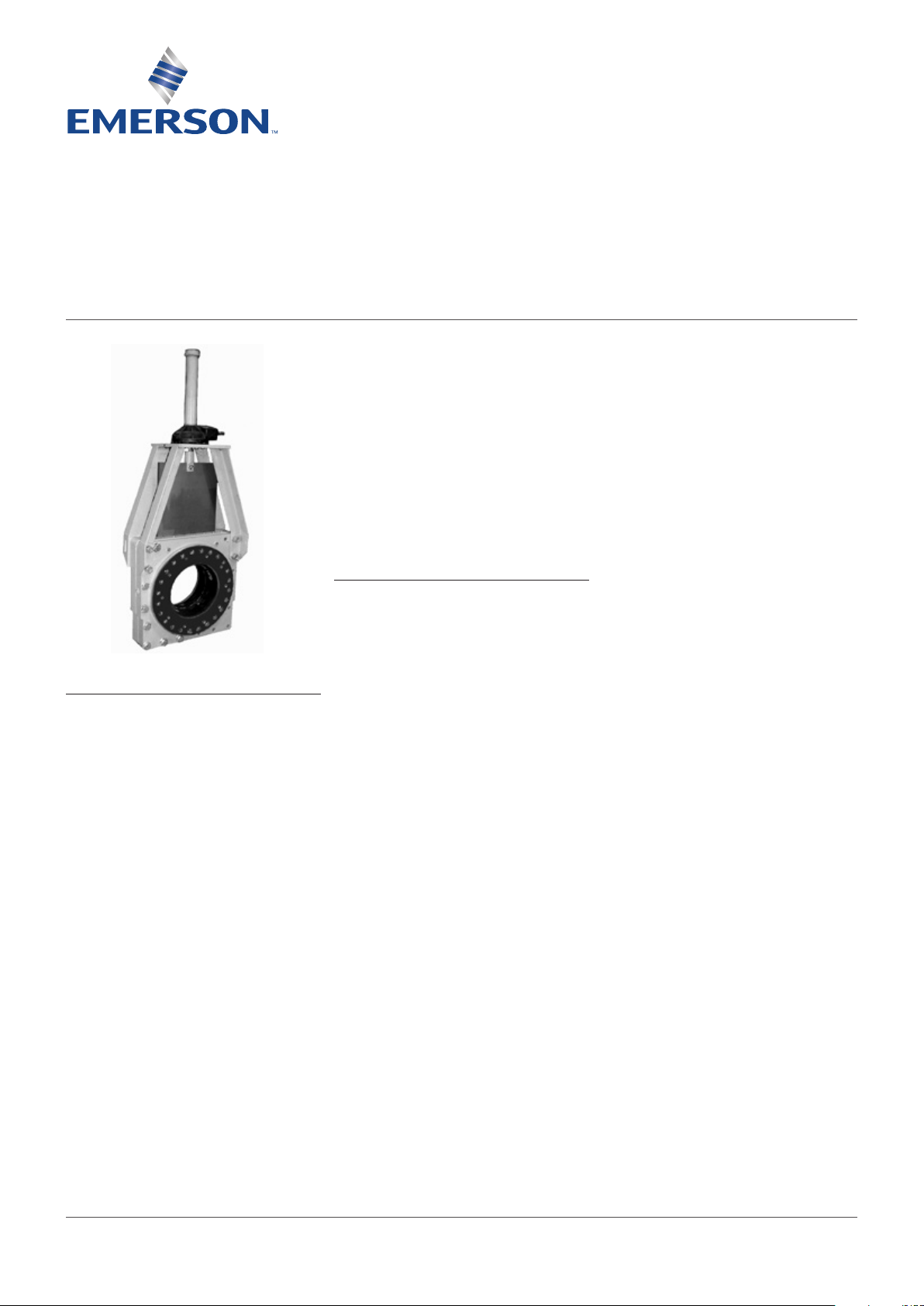
1. The KGF and KGF-HP are packingless,
slurry knife gate valves. All the sealing is
accomplished by the elastomeric sleeves
in the valve housing. The sleeves also form
the wear section for the valve. The gate is
INDEX
1. General information ...................................... 1
2. Initial inspection ............................................ 2
3. Installation instructions ................................ 2
4. Operation ....................................................... 5
5. Lockouts ....................................................... 6
6. General maintenance ................................... 7
7. Spare parts ................................................... 8
8. Storage .......................................................... 9
9. Sleeve replacement .................................... 10
10. Gate support replacement .......................... 12
11. Secondary seal replacement ...................... 12
12. Disassembly and assembly instructions ... 13
13. Field replacement of gates ......................... 16
14. Body flushing and discharge ...................... 17
15. Installation instructions for splash
guardbucket ................................................ 18
16. Installation instructions for splash
guardplate ................................................... 18
17. Lifting ........................................................... 18
18. Manual handwheel actuator assembly ...... 19
19. Bevel gear actuator assembly .................... 19
20. Air cylinder actuator assembly................... 20
21. Hydraulic cylinder actuator assembly ....... 20
removable for inspection or replacement
while the valve is in service. Refer to
Section 13 for gate removal cautions
andinstructions.
2. The KGF and KGF-HP are BIDIRECTIONAL
(two-way shut-off) product and can be
installed without concern over direction of
flow. Since they will shut-off equally with
in either direction, you will find no arrows
or other indicators of a direction of flow or
seatside.
3. Clarkson slurry knife gate valves are
suitable for on-off service only. They are
notto be used in a throttling application.
4. The style, size, pressure rating and material
selection are the responsibility of the piping
system designer.
5. All valves should be operated within the
design pressure and temperature ranges.
Under no circumstances should the valves
be operated at conditions outside these
parameters. Do not exceed 100% of the
maximum pressure rating of the valve at
anytime during its operation. Pressure
spikes beyond the valve’s pressure rating
are solely the responsibility of the user.
© 2017 Emerson. All Rights Reserved.Emerson.com/FinalControl VCIOM-06613-EN 17/08
CLARKSON SERIES KGF AND KGF-HP SLURRY VALVES
InstallatIon and maIntenance InstructIons
2 INITIAL INSPECTION
1. Examine entire valve and report any
damageor discrepancies immediately.
2. Sleeves: visually examine the sleeves
interior, looking for chunking, irregularities
or other damage. It is not recommended
you remove the retainer flanges. Visually
examine the retainer flanges surfaces,
looking for tears, irregularities or other
damage. Check tightness of retainer
flangebolting.
3. Operators: standard manual handwheels
may be shipped loose for field installation,
be sure to fully tighten.
4. Valves are normally shipped with gate in
open position, the recommended position
for installation. Valves supplied with spring
to extend (fail close) cylinder actuators are
shipped with the gate in the closed position.
The KGF and KGF-HP should be installed
with the gate in the open position, exercise
caution when applying air to open this valve
and ensure that it is locked in the open
position when installing in the line.
5. Accessories: if provided, including
solenoids, limit switches, etc., are tested
for functionality prior to shipment. Examine
carefully for damage which may occur
during shipment.
6. Refer to lockouts Section 5 for additional
cautions on spring cylinders
3 INSTALLATION INSTRUCTIONS
Please take note of the specific installation
tagsprovided with each valve.
1. The KGF and KGF-HP are to be installed
with the gate in the fully open position with
the sleeves inserted into the housing halves.
2. KGF: standard mating flanges 3” (DN80)
through24” (DN600) match ASME
B16.5/300, sizes30” and larger are per
MSS-SP44/300 (see Table 4). Optional
drilling to ASME B16.5/150 is available
in certain circumstances. Other flange
drillings including PN10 or PN16 are
available depending on rated pressure of
valve.
KGF-HP: standard mating flanges 3”
(DN80) through 24” (DN600) match ASME
B16.5/300, sizes30” and larger are per
MSS-SP44/300 (see Table 4). Other flange
drillings are available depending on rated
pressure ofvalve.
CAUTION
Valves are normally shipped with gate in
open position, the recommended position for
installation. Valves supplied with spring to extend
(fail close) cylinder actuators are shipped with
the gate in the closed position. Gate should be
actuated to the open position prior to installation,
exercise extreme caution when applying air to
open this valve and ensure that gate is locked
in the open position for installation. Refer to
lockouts section 5 for additional cautions on
spring cylinders.
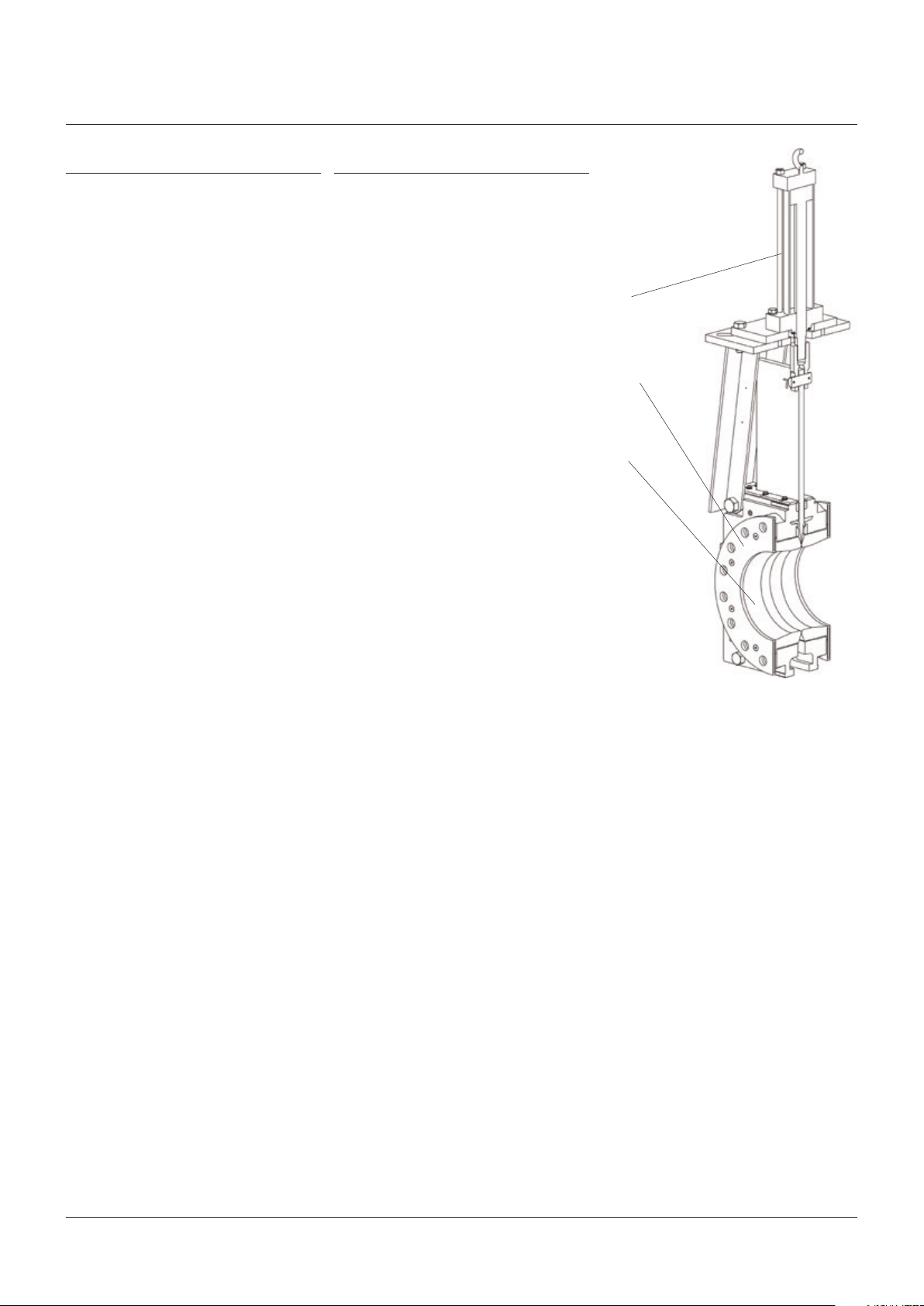
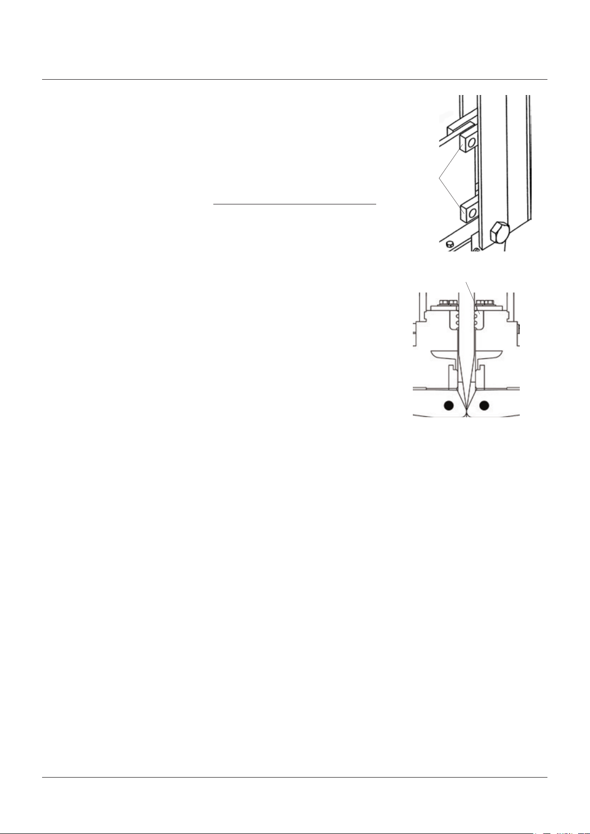
FIGURE 1
Operators
Retainer flanges
Sleeves
2
CLARKSON SERIES KGF AND KGF-HP SLURRY VALVES
InstallatIon and maIntenance InstructIons
3. Tables 1 and 2 state the maximum flange
bolt tightening torques for standard flange
patterns. While the KGF and KGF-HP are
provided with flange bolt patterns that
match ASME B16.5/150 or ASME B16.5/300
flange bolt patterns, they are not designed
to handle the same torque requirements
as an all-metal Class150 or Class300 gate
valve. The KGF and KGF-HP are specialty
valves with a specified maximum flange
torque. Exceeding recommended torque
values will reduce overall valve performance
and may permanently damage the sleeves
and or other components.
4. The KGF and KGF-HP are configured for
installation in conventional bolted flange
connections. Slip on or weld flanges can
be used. The pipeline companion flanges
should be raised or flat face type to insure
full sleeve support and a continuous,
unvarying I.D. If slip-on flanges are used,
the pipe should be cut square and welded
in position with the pipe end matched
evenly with the flange face. Studded flanges
are not compatible with these valves.
Use of other flange connections should
be reviewed and verified by the factory
forcompatibility prior to installation.
5. The mating line flanges must be properly
aligned prior to attempting installation.
Never try to make up for misaligned pipe
flanges by the line bolting.
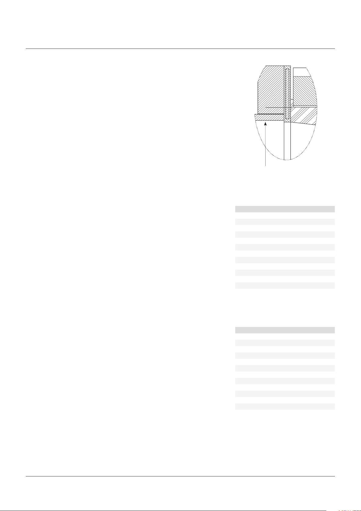
6. Optimum performance of the valve sleeves
may be achieved if the mating pipe I.D. is no
larger than +0.25” (6.5mm) of the retainer
flange I.D. (Refer to Table 4 for retainer
flange dimensions.) Oversized mating pipe
I.D. may subject retainer flange and sleeve
to additional wear.
7. Listed in Table 4 are the fasteners required
for installation.
8. Pipe supports and/or expansion joints
should be used to minimize pipe loads
onvalves.
9. The elastomer coated retainer flange
functions as the gasket for installation
into the pipeline, no additional gaskets
arerequired.
10. Valve is suitable for use in either vertical or
horizontal lines. The valve can be installed
in any position in vertical or horizontal
pipelines. However, valves installed in
an orientation with the actuator below
horizontal may require flushing to prevent
the buildup of solids in the housing and
mayrequire additional actuator support.
Installation notes
A) All slurry knife gate valves are designed and
manufactured to be installed in applications
where no more than 1g of force In excess
of gravity is applied to the valve in any
direction. This 1g force can be an effect
of traffic, wind, or earthquake, etc. Valves
should not be used in applications that
exceed 1g.
B) If valve stem or topworks protrude into
walkways or work areas, valve should
beflagged per company safety policy.
C) All piping systems should contain
independent support mechanisms and
should not utilize the valve as a sole
meansof support.
D) Do not install valve over walkways, electrical
or other critical equipment without the use
of a splash guard device (refer to section 14)
or similar considerations.
FIGURE 2
Retainer flange I.D.
TABLE 1 - MAXIMUM TIGHTENING TORQUE
STANDARD CLASS150 FLANGES
Valve size ft·lbs Nm
3 37 50
4 37 50
6 69 64
8 69 64
10 113 153
12 113 153
14 169 229
16 169 229
18 238 324
20 238 324
24 345 467
30 345 467
36 610 827
TABLE 2 - MAXIMUM TIGHTENING TORQUE
STANDARD CLASS300 FLANGES
Valve size ft·lbs Nm
3 69 94
4 69 94
6 69 94
8 113 153
10 169 229
12 238 324
14 238 324
16 345 467
18 345 467
20 345 467
24 610 827
30 1000 1355
36 1500 2035
3

CLARKSON SERIES KGF AND KGF-HP SLURRY VALVES
InstallatIon and maIntenance InstructIons
TABLE 3 - BOLTING DIMENSIONS CLASS150 FLANGES
Bolt size/
Valve size Retainer inlet diameter Flange diameter Bolt circle diameter Bolt holes
inch/mm inch mm inch mm inch mm UNC inch mm
3” / 80 2.81 71.4 7½ 190.5 6 152.40 4 ⅝-11 3 76.2
4” / 100 3.88 98.6 9 228.6 7½ 190.50 8 ⅝-11 3 76.2
6” / 150 5.81 147.6 11 279.4 9½ 241.30 8 ¾-10 3 76.2
8” / 200 7.75 196.9 13½ 342.9 11¾ 298.50 8 ¾-10 4 101.6
10” / 250 9.81 249.2 16 406.4 14¼ 362.00 12 ⅞-9 4 101.6
12” / 300 11.50 292.1 19 482.6 17 431.80 12 ⅞-9 4½ 114.3
14” / 350 13.25 336.6 21 533.4 18¾ 476.30 12 1-8 4½ 114.3
16” / 400 14.75 374.7 23½ 596.9 21¼ 539.80 16 1-8 4½ 114.3
18” / 450 16.75 425.5 25 635.0 22¾ 577.90 16 1⅛-7 5 127.0
20” / 500 18.50 469.9 27½ 698.5 25 635.00 20 1⅛-7 6 152.4
24” / 600 23.00 584.2 32 812.8 29½ 749.30 20 1¼-7 6½ 165.1
30” / 750 29.00 736.6 38¾ 984.3 36 914.40 28 1¼-7 9 228.6
36” / 900 35.00 889.0 46 1168.4 42¾ 1085.85 32 1½-6 9 228.6
NOTES
• Flange dimensions per ANSI B16.5/150 for 3”-24” and MSS SP44/150 for 30”-36”.
• Type B standard washers are not included in stud lenghts.
• Mating flange thickness assumed to match ANSI B16.5/150 for 3”-24” and MSS SP44/150 for 30”-36”.
• Flange drilled and tapped holes in body over 1” in diameter are normally provided with course threads.
• Stud lengths supplied are minimum for full thread engagement into tapped holes and stud lengths are rounded to nearest 0.5inch.
• Stud lengths are supplied rather than bolt lengths.
• Bolt hole quantity shown below is per side of valve.
no.
thread Stud length (see note)
TABLE 4 - BOLTING DIMENSIONS CLASS300 FLANGES
Bolt size/
Valve size Retainer inlet diameter Flange diameter Bolt circle diameter Bolt holes
inch/mm inch mm inch mm inch mm UNC inch mm
3” ⁄ 80 2.81 71.4 8¼ 209.6 6⅝ 168.30 8 ¾-10 3½ 88.9
4” ⁄ 100 3.88 98.6 10 254.0 7⅞ 200.00 8 ¾-10 3½ 88.9
6” ⁄ 150 5.83 148.1 12½ 317.5 10⅝ 269.90 12 ¾-10 3½ 88.9
8” ⁄ 200 7.86 199.6 15 381.0 13 330.20 12 ⅞-9 4 101.6
10” ⁄ 250 9.80 248.9 17½ 444.5 15¼ 387.40 16 1-8 4½ 114.3
12” ⁄ 300 11.50 292.1 20½ 520.7 17¾ 450.90 16 1⅛-7 5½ 139.7
14” ⁄ 350 13.30 337.8 23 584.2 20¼ 514.40 20 1⅛-7 5½ 139.7
16” ⁄ 400 14.75 374.7 25½ 647.7 22½ 571.50 20 1¼-7 6 152.4
18” ⁄ 450 17.00 431.8 28 711.2 24¾ 628.70 24 1¼-7 6 152.4
20” ⁄ 500 18.50 469.9 30½ 774.7 27 685.80 24 1¼-7 7 177.8
24” ⁄ 600 23.50 596.9 36 914.4 32 812.80 24 1½-6 7½ 190.5
30” ⁄ 750 29.00 736.6 43 1092.2 39¼ 996.95 28 1¾-5 10 254.0
36” ⁄ 900 35.00 889.0 50 1270.0 46 1168.40 32 2-4.5 11 279.4
NOTES
• Flange dimensions per ANSI B16.5/300 for 3”-24” and MSS SP44/300 for 30”-36”.
• Type B standard washers are not included in stud lenghts.
• Mating flange thickness assumed to match ANSI B16.5/300 for 3”-24” and MSS SP44/300 for 30”-36”.
• Flange drilled and tapped holes in body over 1” in diameter are normally provided with course threads.
• Stud lengths supplied are minimum for full thread engagement into tapped holes and stud lengths are rounded to nearest 0.5inch.
• Stud lengths are supplied rather than bolt lengths.
• Bolt hole quantity shown below is per side of valve.
no.
thread Stud length (see note)
4
CLARKSON SERIES KGF AND KGF-HP SLURRY VALVES
InstallatIon and maIntenance InstructIons
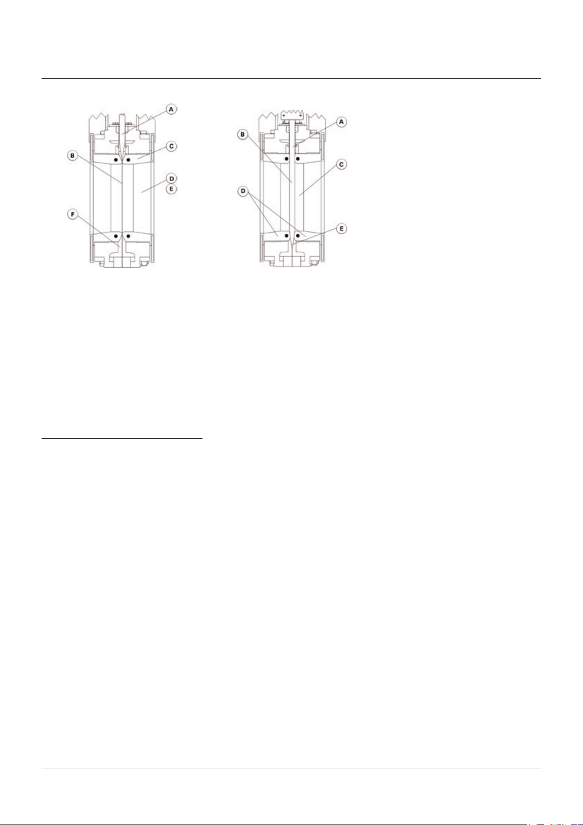
FIGURE 3 - OPEN POSITION FIGURE 4 - CLOSED POSITION
Open position
A) Gate positioned above seals, out of flow.
B) Matching elastomer sleeves seal against
each other under a high compression load.
C) Sleeves act as pressure vessel.
D) No metal parts in contact with slurry.
E) Unobstructed port area eliminates
turbulence, minimizes pressure drop
acrossvalve.
F) No seat cavity where solids can collect
andprevent full gate closure.
4 OPERATION
1. Clarkson slurry knife gate valves are
suitable for on-off service only. They are
notto be used in a throttling application.
2. To close the valve and provide isolation,
the actuator (handwheel, bevel gear,
air/hydraulic cylinder or electric motor
actuator) moves the metal gate in a linear
motion between the elastomeric sleeves
to shut off the flow. To open, reverse the
operation and the gate moves up and out
from between the sleeves, opening the
valveport.
3. Matching elastomer sleeves seal against
each under a high compression load
when the valve is open, creating the valve
pressure vessel. When the valve is closed,
the sleeves seal against the gate face,
isolating upstream from downstream.
SeeFigures 3 and 4.
It is normal for the KGF and KGF-HP
to discharge media during opening and
closing cycles. Some additional discharge
may continue for a time after completion
of the open cycle. This helps prevent
any solids from building up between the
sleeves that would prevent a tight seal
when the valve is fully open or closed.
Dischargecanbecontrolled with the use of
a splash guarddevice (refertosection 14).
Closed position
A) Gate travels through sleeves to provide
blindflange shut-off, allowing opportunity
for media to expel to atmosphere.
B) 100% Isolation-bubble tight shut-off results
in absolutely zero downstream leakage.
C) When properly installed and maintained,
the KGF is designed to provide
man-safeisolation.
D) Double-seated design provides bidirectional
flow and shut-off.
E) Controlled stroke prevents gate from
penetrating too far, minimizing stress
onsleeve.
Depending on the pressure rating, some
models of the KGF and KGF-HP include
a splash guard device as standard. Do
not install valve over walkways, electrical
or other critical equipment without the
use of a splash guard device or similar
considerations.
4. As the gate strokes, a gap is created
between the facing sleeves, allowing any
media that could potentially clog or jam
thevalve to be purged out from between
thesleeves, and potentially expelled
outsidethe valve housing to atmosphere.
5. The KGF and KGF-HP incorporate a
built-in clean-out area at the base of the
housing assembly. The clean-out area
may be enclosed by a removable splash
guard device. Depending on the pressure
rating, some models of the KGF and
KGF-HP include a splash guard device
as standard. This splash guard device
will allow controlled drainage of any
accumulated solids that may prevent full
gate closure. Flush water can be used to
improve the drainage efficiency. With the
splash guard device in place, any solids,
slurry, or flush water ejected from the valve
can be handled in a controlled manner.
See Section14forsplash guard device
installation instructions.
5
CLARKSON SERIES KGF AND KGF-HP SLURRY VALVES
InstallatIon and maIntenance InstructIons
6. All valves should be operated within the
design pressure and temperature ranges.
Under no circumstances should the
valves be operated at conditions outside
theseparameters.
Note: actuated Clarkson valves have a
maximum recommend stroke speed
of1”per second. Exceeding this speed can
shorten sleeve life and may void warranty.
Speed controls provided by factory will
require adjustment in the field to obtain
proper stroke speed against actual
operating conditions. Refer to Section 14
foradditional inormation on discharge.
7. The operator of any valve should have an
understanding of the effects of opening/
closing the valve with regards to its role
in the overall piping system. Operators
of valves under pressure should take
caution to ensure that the valve is in good
operatingcondition prior to operating it
under pressure.
8. Certain processes contain hazardous and/or
otherwise unstable media. Care should be
taken in these circumstances to ensure the
operator is aware of the specific health and
safety risks associated with that medium.
9. When operating the valve stand clear of any
moving parts such as the stem and/or gate
assembly, use of gloves is suggested when
operating manual valves to minimize the
risk of injury.
10. All manually operated valves are designed
for hand input. Do not apply excessive input
torque via pipe wrenches, ‘cheater bars’,
or other devices. If a manual handwheel
actuated valve is difficult to operate due to
torque requirements, it is recommended
that the valve be supplied with or converted
to a bevel gear, air/hydraulic cylinder or
electric motor actuator.
11. Electric motor actuated valves should be
left in their factory set condition, unless
the system operating parameters dictate
a change. If changes are necessary, they
should be performed in small increments
using the lightest/lowest setting possible
to achieve the desired performance and
then the valve/actuator function inspected.
Excess torque and/or thrust in the motor
settings may damage or lockup the valve.
12. Clarkson KGF and KGF-HP valves are
position seated and should never be
torqueseated. Do not use the motor
torquesettings to seat the valve.
13. Care should be taken to ensure that
electrical motors are wired correctly to the
power source. Incorrect phasing of 3-phase
wiring may cause valve/motor damage.
5 LOCKOUTS
Open and closed lockout positions are optional
on the KGF and KGF-HP. Optional lockout pins
may be supplied by Emerson or customer may
use their own suitable pin. (Contact factory
forpin specifications.)
CAUTION
If lockout pins are used on automated valves, the
open & closed lockout brackets are designed to
resist the normal valve operating thrust. In order
to assure complete lockout compliance, any
double acting air cylinder, hydraulic cylinder or
electric motor actuated valve must be placed in
a ZERO ENERGY STATE by isolating all potential
energy sources including electricity, operator air
supply or hydraulic fluids.
In the case of a single acting spring to close
or spring to open cylinder with the spring
compressed, the mechanical energy cannot
be placed in the ZERO ENERGY STATE. When
compressed, the spring will cause unwanted
gate movement if inlet air pressure is not
maintained on the non-spring side of the
actuator. Specific care must be taken to insert
or remove lockout pins. To insert or remove
lockout pins.
- Spring extended (uncompressed): isolate air
supply from cylinder actuator.
- Spring retracted (compressed): maintain
air pressure on the non-spring side of
theactuator.
Take great care when inserting and removing the
lockout pin. If the gate moves during the insertion
or removal process, injury may occur.
FIGURE 5
brackets
FIGURE 6
Lockout
Secondary seal
6
 Loading...