

Page 1
00825-0100-3560, Rev AA
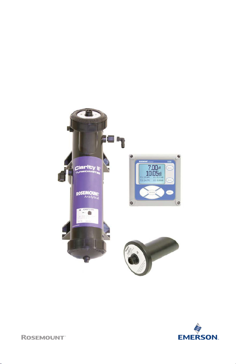
Rosemount™ Clarity II T1056
Turbidmeter
Turbidity Measurement System
Quick Start Guide
April 2020
Page 2

Quick Start Guide April 2020
Essential instructions
Read this page before proceeding!
Your instrument purchase from Emerson is one of the finest available for your particular application.
These instruments have been designed and tested to meet many national and international standards.
Experience indicates that its performance is directly related to the quailty of the installation and
knowledge of the user in operating and maintaining the instrument. To ensure continued operation to
the design specifications, read this Manual thoroughly before proceeding with installation,
commissioning, operation, and maintenance of this instrument.
• Failure to follow the proper instructions may cause any one of the following situations to occur:
loss of life, personal injury, property damage, damage to this instrument, and warranty
invalidation.
• Ensure that you have received the correct model and options from your purchase order. Verify
that this Quick Start Guide covers your model and options. If it does not, call 800 854 8257 or 949
757 8500 to request the correct Quick Start Guide.
• For clarification of instructions, contact your Rosemount representative.
• Follow all warnings, cautions, and instructions marked on and supplied with the product.
• Use only qualified personnel to install, operate, program, and maintain the product.
• Educate your personnel on the proper installation, operation, and maintenance of this product.
• Install equipment as specified in the installation instructions of the appropriate Reference Manual
and per applicable local and national codes. Connect all products to the proper electrical and
pressure sources.
• Use only factory documented components for repair. Tampering or unauthorized substitution of
parts and procedures can affect the performance and cause unsafe operation of your process.
• All equipment doors must be closed, and protective covers must be in place unless qualified
personnel are performing maintenance.
WARNING
Risk of electrical shock
Installation and servicing of this product may expose personnel to dangerous voltages.
Equipment protected throughout by double insulation.
Disconnect main power wired to separate power source before servicing.
Do not operate or energize instrument with case open.
Signal wiring within this box must be rated at least 240 V.
Non-metallic cable strain reliefs do not provide grounding between conduit connections. Use
grounding type bushings and jumper wires.
Unused cable conduit entries must be securely sealed by non-flammable closures to provide
exposure integrity in compliance with personal safety and environmental protection
requirements. Unused conduit openings must be sealed with NEMA 4X or IP65 conduit plugs to
maintain the ingress protection rating (IP65).
Electrical installation must be in accordance with the National Electrical Code (ANSI/NFPA-70)
and/or any other national or local codes.
Operate only with front panel fastened and in place.
Proper use and configuration is the operator's responsibility.
2 Emerson.com/Rosemount
Page 3
April 2020 Quick Start Guide
WARNING
This product is not intended for use in the light industrial, residential, or commercial
environments per the instrument's certification to EN50081-2.
CAUTION
Radio interference
This product generates, uses, and can radiate radio frequency energy and thus can cause radio
communication interference. Improper installation or operation may increase such interference. As
temporarily permitted by regulation, this unit has not been tested for compliance within the limits of
Class A computing devices, pursuant to Subpart J of Part 15 of FCC rules, which are designed to provide
reasonable protection against such interference.
Operation of this equipment in a residential area may cause interference, in which case the
operator, at his own expense, will be required to take whatever measures may be required to
correct the interference.
WARNING
Physical access
Unauthorized personnel may potentially cause significant damage to and/or misconfiguration of end
users’ equipment. This could be intentional or unintentional and needs to be protected against.
Physical security is an important part of any security program and fundamental to protecting your
system. Restrict physical access by unauthorized personnel to protect end users’ assets. This is true for
all systems used within the facility.
Warranty
Seller warrants that the firmware will execute the programming instructiosn provided by Seller, and
that the Goods manufactured or services provided by Seller will be free from defects in materials or
workmanship under normal use and care until the expiration of the applicable warranty period. Goods
are warranted for twelve (12) months from the date of intial installation or eighteen (18) months from
the date of shipment by Seller, whichever period expires first. Consumables, such as glass electrodes,
membranes, liquid junctions, electrolyte, O-rings, catalytic beads, etc. and services are warranted for a
period of 90 days from the date of shipment or provision.
Products purchased by Seller for resale to Buyer ("Resale Products") shall carry only the warranty
extended by the original manufacturer. Buyer agrees that Seller has no liability for Resale Products
beyond making a reasonable commercial effeort to arrange for procurement and shipping of the
Resale Products.
If Buyer discovers any warranty defects and notifies Seller thereof in writing during the applicable
warranty period, Seller shall, at its option, promptly correct any errors that are found by Seller in the
firmware or Services, or repair or replace F.O.B. point of manufacture that portion of Goods or
firmware found by Seller to be defective, or refund the purchase price of the defective portion of the
Goods/Services.
All replacements or repairs necessitated by inadequate maintenance, normal wear and usage,
unsuitable power sources, unsuitable environmental conditions, accident, misuse, improper
installation, modification, repair, storage or handling, or any other cause not the fault of Seller are not
covered by this limited warranty, and shall be at Buyer's expense. Seller shall not be obligated to pay
any costs or charges incurred by Buyer or by any other party except as may be agreed upon in writing in
advance by an authorized Seller representative. All costs of dismantling, reinstallation and freight and
the time and expenses of Seller's personnel for site travel and diagnosis under this warranty clause shall
be borne by Buyer unless accepted in writing by Seller.
Quick Start Guide 3
Page 4

Quick Start Guide April 2020
Goods repaired and parts replaced during the warranty period shall be in warranty for the remainder of
the original warranty period or ninety (90) days, whichever is longer. This limited warranty is the only
warranty made by Seller and can be amended only in a writing signed by an authorized representative
of Seller. Except as otherwise expressly provided in the Agreement, THERE ARE NO REPRESENTATIONS
OR WARRANTIES OF ANY KIND, EXPRESSED OR IMPLIED, AS TO MERCHANTABILITY, FITNESS FOR
PARTICULAR PURPOSE, OR ANY OTHER MATTER WITH RESPECT TO ANY OF THE GOODS OR SERVICES.
Contents
Install........................................................................................................................................... 5
Wire........................................................................................................................................... 16
EU Declaration of Conformity.....................................................................................................26
China RoHS Table....................................................................................................................... 28
4 Emerson.com/Rosemount
Page 5

April 2020 Quick Start Guide
1 Install
1.1 Unpack and inspect
The Rosemount™ Clarity II Turbidmeter is a complete system for the
determination of turbidity in drinking water. The system consists of the
transmitter, sensor(s), cable(s), and flow chamber/debubbler(s). Consult the
table to verify that you have received the parts for the option you ordered.
Table 1-1: Rosemount Clarity II Turbidmeter Parts
Item Model/part number
Single input turbidity transmitter 1056-03-27-38-AN
Dual input turbidity transmitter 1056-03-27-37-AN
Single input turbidity transmitter with
®
HART
Dual input turbidity transmitter with
HART
Sensor - EPA standards 8-0108-0002-EPA
Sensor - ISO standard 8-0108-0003-ISO
Cable - 3 ft. (0.9 m) 2413800
Cable - 20 ft. (6.1 m) 2409700
Cable - 50 ft. (15.2 m) 2409800
Calibration cup 2410100
Molded chamber/debubbler 24170-00
1056-03-27-38-HT
1056-03-27-38-HT
Note
The transmitter model number is printed on a label attached to the side of
the instrument.
1.2
Install
1.2.1 General installation information
1. Although the transmitter is suitable for outdoor use, do not install it
in direct sunlight or in areas of extreme temperatures.
2. Install the transmitter in an area where vibration and
electromagnetic and radio frequency interference are minimized or
absent.
Quick Start Guide 5
Page 6

Quick Start Guide April 2020
3. Keep the transmitter and sensor wiring at least one foot (0.3 m) from
high voltage conductors. Be sure there is easy access to the
transmitter.
4. The transmitter is suitable for panel, pipe, or surface mounting. Refer
to the figures below.
WARNING
Electrical shock
Electrical installation must be in accordance with the National Electrical
Code (ANSI/NFPA-70) and/or any other applicable national or local
codes.
Do not operate or energize instrument with case open.
6 Emerson.com/Rosemount
Page 7
April 2020 Quick Start Guide
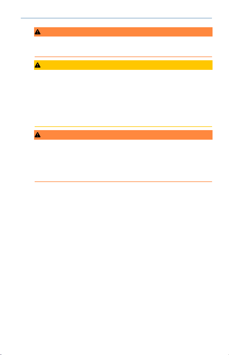
Figure 1-1: Panel Mounting Dimensions
A. Panel supplied by others. Maximum thickness: 3.75 in. (9.52 mm)
B. 4X mounting brackets and screws provided with instrument
Note
Panel mounting seal integrity (4/4X for outdoor applications is your
responsibility.
Quick Start Guide 7
Page 8
Quick Start Guide April 2020
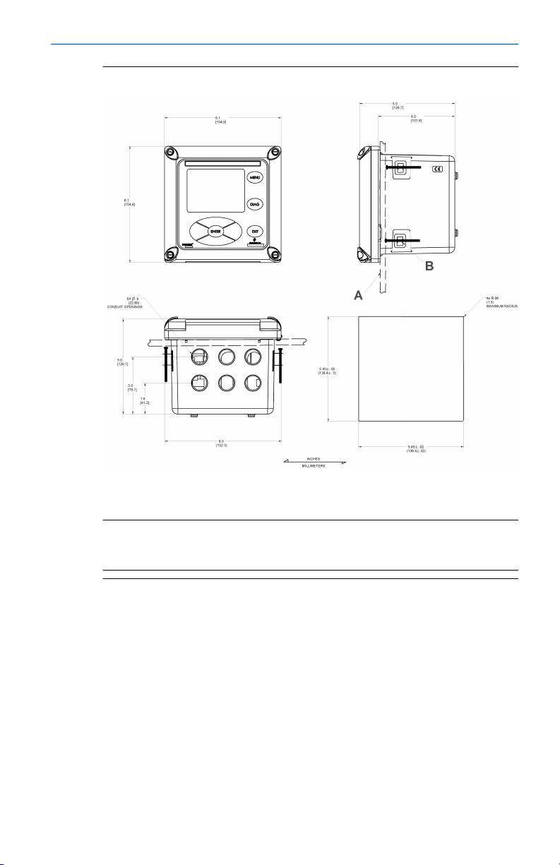
Figure 1-2: Wall Mounting Dimensions
A. 4X cover screw
8 Emerson.com/Rosemount
Page 9
April 2020 Quick Start Guide
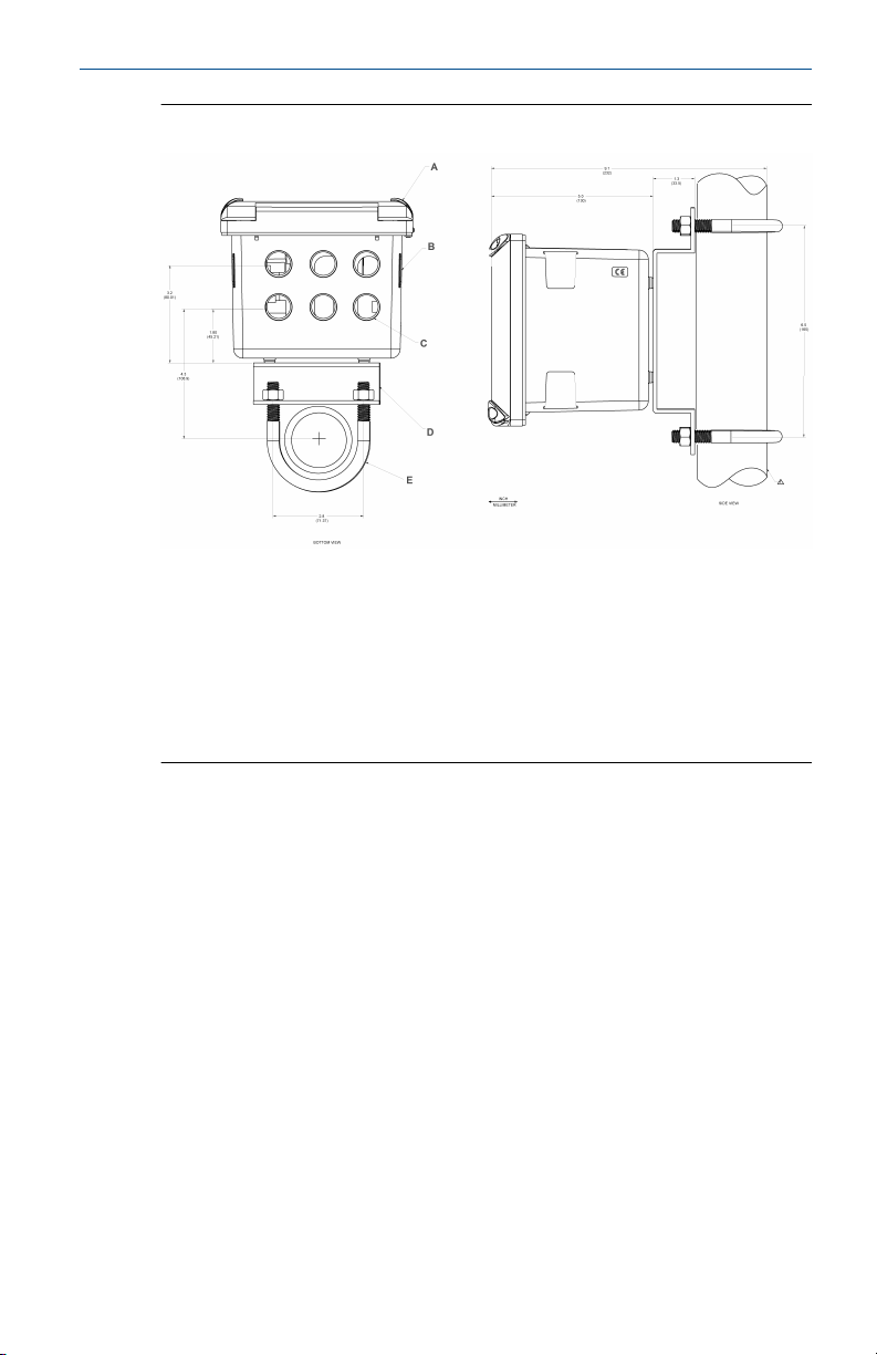
Figure 1-3: Pipe Mounting Dimensions
A. Front panel
B. Panel & pipe mount enclosure
C. 6x Ø conduit openings
D. 2-in. pipe mount bracket
E. 2X set U-bolts for 2-in. pipe in kit PN 23280-00
The front panel is hinged at the bottom. The panel swings down for easy
access to the wiring locations.
1.3
Quick Start Guide 9
Install debubbler assembly
See Figure 1-4 for installation.
Page 10
Quick Start Guide April 2020
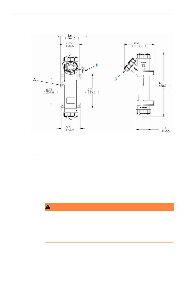
Figure 1-4: Debubbler and Flow Chamber
A. Inlet
B. Outlet
C. Sensor port
Procedure
1. Connect the sample line to the inlet fitting.
The fitting accepts ¼-in. OD tubing. See Sample point for
recommended installation of the sample port.
2. Attach a piece of ⅜-in. ID soft tubing to the drain fitting.
The debubbler must drain to atmosphere.
WARNING
High pressure and temperature
Before removing the sensor, be absolutely certain that the process
pressure is reduced to 0 psig and the process temperature is lowered
to a safe level!
10 Emerson.com/Rosemount
Page 11

April 2020 Quick Start Guide
CAUTION
Reading errors
During operation, the debubbler is under pressure. A 0.040 in. (1
mm) orifice in the outlet provides the pressure. Back pressure helps
prevent outgassing, which can lead to bubbles accumulating on the
sensor face, resulting in erroneous readings.
Do not exceed 30 psig (308 kPa abs) inlet pressure.
The amount of pressure in the debubbler can be estimated from the
flow rate. See Table 1-2.
Table 1-2: Approximate Debubbler Pressure as a Function of Flow
(0.040 Inch Outlet Orifice)
gph psig mL/min kPa abs
2 1 100 110
4 3 200 120
6 8 300 140
8 14 400 160
10 21 500 190
11 26 600 240
12 31 700 280
-- -- 800 340
To control and monitor sample flow, a valved rotameter with fittings
is available (PN 24103-00).
3. Attach the rotameter to the debubbler outlet.
You can also use the rotameter to increase back pressure on the
debubbler if additional pressure is needed to prevent outgassing.
Quick Start Guide 11
Page 12

Quick Start Guide April 2020
1.4 Install sensor
Figure 1-5: Sensor
A. O-ring PN 9550145
B. Light source
C. Detector
Procedure
1. Unscrew the nut on the side of the debubbler.
2. Insert the sensor in the mouth of the measuring chamber.
Be sure the pin on the debubbler lines up with the hole in the sensor.
3. Replace the nut.
4. Remove the protective cap from the sensor.
5. Screw the cable onto the receptacle.
The plug and receptacle are keyed for proper alignment.
The sensor is rated to IP65 when properly connected to the cable.
Postrequisites
To prevent possible water damage to the connector contacts, be sure the
cable receptacle and the connector on the back of the sensor are dry when
connecting or disconnecting the cable.
12 Emerson.com/Rosemount
Page 13

April 2020 Quick Start Guide
1.5 Sample point
Locate the sample tap to minimize pickup of sediment or air.
See Figure 1-6.
Figure 1-6: Sampling for Turbidity
If possible, install a sampling port that extends one or two inches (25 - 50
mm) into the pipe. Use 1/4 in. OD rigid plastic tubing. Avoid soft plastic
tubing if possible. To reduce sample lag time, install the debubbler and flow
chamber as close to the sample tap as possible.
Quick Start Guide 13
Page 14

Quick Start Guide April 2020
Figure 1-7: Non Incendive Field Wiring Installation (CSA) 1056-27/37
A. Sensor cable is shielded. Max cable length is 50 ft. (15.2 m).
B. Sensor cable is shielded. Max cable length is 50 ft. (15.2 m).
C. Metal conduit
D. Metal conduit
E. Ground connection may be made in hazardous area.
F. Metal conduit
WARNING
Flammable
Use with non-flammable process media only.
Note
A. Installation must conform to the CEC.
B. Seal required at each conduit entrance.
C. During installation, leave maximum amount of jacket insulation possible
on N.I. field wiring within instrument enclosure. After termination, wrap
N.I. field wiring within enclosure with mylar tape to ensure adequate
double insulation remains.
Unless otherwise specified.
14 Emerson.com/Rosemount
Page 15

April 2020 Quick Start Guide
Figure 1-8: Non-Incendive Field Wiring Connection for Class 1, Division
1, Group D
Turbidity sensor board
Option -27/-37: turbidity
May only be used with a Clarity II Turbidity Sensor.
Quick Start Guide 15
Page 16

Quick Start Guide April 2020
2 Wire
2.1 General wiring information
The transmitter is easy to wire.
It includes removable connectors and slide-out signal input boards.
2.1.1 Removable connectors and signal input boards
The transmitter uses removable signal input boards and communication
boards for ease of wiring and installation.
You can remove each of the signal boards either partially or completely from
the enclosure for wiring. The transmitter has three slots for placement of up
to two signal input boards and one communication board.
Slot 1 - left Slot 2 - center Slot 3 - right
Communication board Input board 1 Input board 2
2.1.2 Signal input boards
Slots 2 and 3 are for signal input measurement boards.
Procedure
1. Wire the sensor leads to the measurement board following the lead
locations marked on the board.
2. Carefully slide the wired board fully into the enclosure slot and take
up the excess sensor cable through the cable gland.
3. Tighten the cable gland nut to secure the cable and ensure a sealed
enclosure.
2.1.3 Digital communication boards
2.1.4 Alarm relays
Emerson supplies four alarm relays with the switching power supply (85 to
264 Vac, 03 order code) and the 24 Vdc power supply (20 - 30 Vdc, 02 order
code). You can use all relays for process measurement(s) or temperature.
You can also configure any relay as a fault alarm instead of a process alarm.
In addition, you may configure any relay independently and program it to
activate pumps or control valves.
As process alarms, alarm logic (high or low activation or USP*) and
deadband are user-programmable. Customer-defined failsafe operation is
supported as a programmable menu function to allow all relays to be
energized or not energized as a default condition upon powering the
transmitter. You may program the USP* alarm to activate when the
16 Emerson.com/Rosemount
Page 17

April 2020 Quick Start Guide
conductivity is within a user-selectable percentage of the limit. USP*
alarming is available only when a contacting conductivity measurement
board is installed.
2.2 Prepare conduit openings
The transmitter enclosure has six conduit openings. Four conduit openings
are fitted with conduit plugs.
Conduit openings accept ½-in. conduit fittings or PG 13.5 cable glands. To
keep the case watertight, block unused openings with NEMA® 4X or IP65
conduit plugs.
Note
Use watertight fittings and hubs that comply with the requirements of
UL514B. Connect the conduit hub to the conduit before attaching the fitting
to the transmitter (UL508-26 16).
2.3 Prepare sensor cable
The Rosemount T1056 is intended for use with all Rosemount sensors. Refer
to the sensor installation instructions for details on preparing sensor cables.
2.4 Power, output, and sensor connections
2.4.1 Power wiring
Emerson offers two power supplies for the Rosemount T1056
1. 24 Vdc (20-30 V) power supply (02 ordering code)
2. 85-265 Vac switching power supply (03 ordering code)
AC mains (115 or 230 V) leads and 24 Vdc leads are wired to the power
supply board which is mounted vertically on the left side of the main
enclosure cavity. Each lead location is marked clearly on the power supply
board. Wire the power leads to the power supply board using the lead
markings on the board.
Quick Start Guide 17
Page 18

Quick Start Guide April 2020
Figure 2-1: 24 Vdc Power Supply (02 Ordering Code)
2.4.2 Current output wiring
Emerson ships all instruments with two 4-20 mA current outputs. Wiring
locations for the outputs are on the main board which is mounted on the
hinged door of the instrument.
Wire the output leads to the correct position on the main board using the
lead markings (+/positive, -/negative) on the board. Emerson provides male
mating connectors with each unit.
For best EMI/RFI protection use shielded output signal cable enclosed in an
earth-grounded metal conduit. Connect the shield to earth ground. AC
wiring should be 14 gauge or greater. Provide a switch or breaker to
disconnect the analyzer from the main power supply. Install the switch or
breaker near the analyzer and label it as the disconnecting device for the
analyzer.
Keep sensor and output signal wiring separate from power wiring. Do not
run sensor and power wiring in the same conduit or together in a cable tray.
18 Emerson.com/Rosemount
Page 19

April 2020 Quick Start Guide
Figure 2-2: Current Output Wiring
2.4.3 Alarm relay wiring
Emerson supplies four alarm relays with the switching power supply (85 to
265 Vac, 03 order code) and the 24 Vdc power supply (20-30 Vdc, 02 order
code).
Wire the relay leads on each of the independent relays to the correct
position on the power supply board using the printed lead markings (NO/
Normally open, NC/Normally closed, or Com/Common) on the board. See
Figure 2-3.
Figure 2-3: Alarm Relay Wiring for Rosemount 1056 Switching Power
Supply (03 Order Code)
Table 2-1: Performance Specifications
NO1
Relay 1COM1
NC1
Quick Start Guide 19
Page 20

Quick Start Guide April 2020
Table 2-1: Performance Specifications (continued)
NO2
COM2
NC2
NO3
NC3
NO4
NC4
Relay 2
Relay 3COM3
Relay 4COM4
2.4.4 Sensor wiring to signal boards
Plug the pre-terminated sensor cable connector directly into the turbidity
signal board mating connector.
WARNING
Electrical shock
Electrical installation must be in accordance with the National Electrical
Code (ANSI/NFPA-70) and/or any other applicable national or local codes.
2.4.5 Wire sensor cable
The sensor cable is pre-wired to a plug that inserts into a receiving socket on
the signal board.
See Figure 2-4.
20 Emerson.com/Rosemount
Page 21

April 2020 Quick Start Guide
Figure 2-4: Turbidity Signal Board with Plug-in Sensor Connection
The cable also passes through a strain relief fitting. To install the cable:
Procedure
1. Remove the wrenching nut from the strain relief fitting.
2. Insert the plug through the hole in the bottom of the enclosure
nearest the sensor socket. Seat the fitting in the hole.
3. Slide the wrenching nut over the cable plug and screw it onto the
fitting.
4. Loosen the cable nut so the cable slides easily.
5. Insert the plug into the appropriate receptacle. To remove the plug,
squeeze the release clip and pull straight out.
6. Adjust the cable slack in the enclosure and tighten the cable nut.
Be sure to allow sufficient slack to avoid placing stress on the cable
and connections.
7. Plug the cable into the back of the sensor.
The sensor is rated to IP65 when properly connected to the cable. To
prevent possible water damage to the connector contacts, be sure
Quick Start Guide 21
Page 22

Quick Start Guide April 2020
the cable receptacle and the connector on the back of the sensor are
dry when connecting or disconnecting the cable.
8. Place the sensor in either the measuring chamber or the calibration
cup.
Important
The sensor must be in a dark place when power is first applied to
transmitter.
Note
If S1 Warning appears, check sensor cable connection and
confirm sample water flow at debubbler drain outlet.
Important
When using EPA/incandescent sensors (P 8-0108-0002-EPA):
• Do not power up the instrument without the sensor connected.
• Do not disconnect and reconnect a sensor while a transmitter is
powered.
If this is inconvenient or cannot be avoided:
• Cycle power to the instrument after connecting to the sensor or
• Perform a slope calibration or standard calibration routine after
connecting the sensor.
Following these guidelines will extend the life of the incandescent lamp and
avoid premature warnings and faults due to reduced lamp life.
22 Emerson.com/Rosemount
Page 23

April 2020 Quick Start Guide
Figure 2-5: Power Wiring for Rosemount 1056 85-265 Vac Power Supply
(03 Ordering Code)
A. To main board
B. Earth ground
C. Neutral
D. Line
Quick Start Guide 23
Page 24

Quick Start Guide April 2020
Figure 2-6: Power Wiring for Rosemount 1056 254 Vdc Power supply
(02 Ordering Code)
A. To main PCB
24 Emerson.com/Rosemount
Page 25

April 2020 Quick Start Guide
Figure 2-7: Output Wiring for Rosemount 1056 Main PCB
A. To power supply PCB
B. Analog output 1
C. Analog output 2
D. To digital I/O PCB
E. To sensor 1 PCB
F. To sensor 2 PCB
Quick Start Guide 25
Page 26

Quick Start Guide April 2020
A EU Declaration of Conformity
26 Emerson.com/Rosemount
Page 27

April 2020 Quick Start Guide
Quick Start Guide 27
Page 28

Quick Start Guide April 2020
B China RoHS Table
28 Emerson.com/Rosemount
Page 29

April 2020 Quick Start Guide
Quick Start Guide 29
Page 30

Quick Start Guide April 2020
30 Emerson.com/Rosemount
Page 31

April 2020 Quick Start Guide
Quick Start Guide 31
Page 32

GLOBAL HEADQUARTERS
6021 Innovation Blvd.
Shakopee, MN 55379
+1 866 347 3427
+1 952 949 7001
RMTNA.RCCPO@Emerson.com
*00825-0100-3560*
Quick Start Guide
00825-0100-3560, Rev. AA
April 2020
NORTH AMERICA
Emerson Automation Solutions
8200 Market Blvd
Chanhassen, MN 55317
Toll Free +1 800 999 9307
F +1 952 949 7001
RMTNA.RCCPO@Emerson.com
MIDDLE EAST AND AFRICA
Emerson Automation Solutions
Emerson FZE
Jebel Ali Free Zone
Dubai, United Arab Emirates, P.O. Box
17033
+971 4 811 8100
+971 4 886 5465
RMTNA.RCCPO@Emerson.com
LinkedIn.com/company/Emerson-
Automation-Solutions
Twitter.com/rosemount_news
Facebook.com/Rosemount
Youtube.com/RosemountMeasurement
EUROPE
Emerson Automation Solutions
Neuhofstrasse 19a PO Box 1046
CH-6340 Baar
Switzerland
+41 (0) 41 768 6111
+41 (0) 41 768 6300
RMTNA.RCCPO@Emerson.com
ASIA-PACIFIC
Emerson Automation Solutions
1 Pandan Crescent
Singapore 128461
Republic of Singapore
+65 6 777 8211
+65 6 777 0947
RMTNA.RCCPO@Emerson.com
©
2020 Emerson. All rights reserved.
The Emerson logo is a trademark and service
mark of Emerson Electric Co. Rosemount is a
mark of one of the Emerson family of companies.
All other marks are the property of their
respective owners.
 Loading...