

Page 1
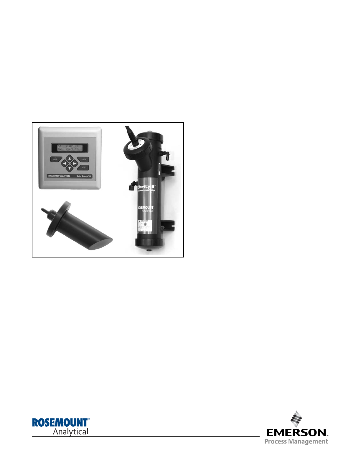
Clarity II™ Turbidimeter
Turbidity Measurement System
Instruction Manual
PN 51-T1055/rev.I
February 2006
Page 2

ESSENTIAL INSTRUCTIONS
READ THIS PAGE BEFORE PROCEEDING!
Your purchase from Rosemount Analytical, Inc. has
resulted in one of the finest instruments available for
your particular application. These instruments have
been designed, and tested to meet many national and
international standards. Experience indicates that its
performance is directly related to the quality of the
installation and knowledge of the user in operating and
maintaining the instrument. To ensure their continued
operation to the design specifications, personnel
should read this manual thoroughly before proceeding
with installation, commissioning, operation, and maintenance of this instrument. If this equipment is used in
a manner not specified by the manufacturer, the protection provided by it against hazards may be impaired.
• Failure to follow the proper instructions may cause
any one of the following situations to occur: Loss of
life; personal injury; property damage; damage to
this instrument; and warranty invalidation.
• Ensure that you have received the correct model
and options from your purchase order. Verify that
this manual covers your model and options. If not,
call 1-800-854-8257 or 949-757-8500 to request
correct manual.
• For clarification of instructions, contact your
Rosemount representative.
• Follow all warnings, cautions, and instructions
marked on and supplied with the product.
• Use only qualified personnel to install, operate,
update, program and maintain the product.
• Educate your personnel in the proper installation,
operation, and maintenance of the product.
• Install equipment as specified in the Installation
section of this manual. Follow appropriate local and
national codes. Only connect the product to electrical and pressure sources specified in this manual.
• Use only factory documented components for repair.
Tampering or unauthorized substitution of parts and
procedures can affect the performance and cause
unsafe operation of your process.
• All equipment doors must be closed and protective
covers must be in place unless qualified personnel
are performing maintenance.
• If this equipment is used in a manner not specified
by the manufacturer, the protection provided by it
against hazards may be impaired.
WARNINGS
RISK OF ELECTRICAL SHOCK
Equipment protected throughout by double insulation.
• Installation of cable connections and servicing of this
product require access to shock hazard voltage levels.
• Main power and relay contacts wired to separate power
source must be disconnected before servicing.
• Do not operate or energize instrument with case open!
• Signal wiring connected in this box must be rated at
least 240 V.
• Non-metallic cable strain reliefs do not provide grounding
between conduit connections! Use grounding type bushings and jumper wires.
• Unused cable conduit entries must be securely sealed by
non-flammable closures to provide enclosure integrity in
compliance with personal safety and environmental protection requirements. Unused conduit openings must be
sealed with NEMA 4X or IP65 conduit plugs to maintain
the ingress protection rating (NEMA 4X).
• Electrical installation must be in accordance with the
National Electrical Code (ANSI/NFPA-70) and/or any
other applicable national or local codes.
• Operate only with front and rear panels fastened and in
place over terminal area.
• Safety and performance require that this instrument be
connected and properly grounded through a three-wire
power source.
• Proper relay use and configuration is the responsibility
of the user.
CAUTION
This product generates, uses, and can radiate radio frequency energy and thus can cause radio communication
interference. Improper installation, or operation, may
increase such interference. As temporarily permitted by regulation, this unit has not been tested for compliance within
the limits of Class A computing devices, pursuant to
Subpart J of Part 15, of FCC Rules, which are designed to
provide reasonable protection against such interference.
Operation of this equipment in a residential area may cause
interference, in which case the user at his own expense, will
be required to take whatever measures may be required to
correct the interference.
WARNING
This product is not intended for use in the light
industrial, residential or commercial environments
per the instrument’s certification to EN50081-2.
Emerson Process Management
Rosemount Analytical Inc.
2400 Barranca Parkway
Irvine, CA 92606 USA
Tel: (949) 757-8500
Fax: (949) 474-7250
http://www.raihome.com
© Rosemount Analytical Inc. 2006
Page 3
C
QUICK START GUIDE
FOR CLARITY II TURBIDIMETER
1. Refer to Section 2.0 for installation instructions.
2. The sensor cable is pre-wired to a plug that inserts into a receiving socket in the analyzer. The cable also passes
through a strain relief fitting. To install the cable…
a. Remove the wrenching nut from the strain relief fitting.
b. Insert the plug through the hole in the bottom of the enclosure nearest the sensor socket. Seat the fitting in the
hole.
c. Slide the wrenching nut over the plug and screw it onto the fitting.
d. Loosen the cable nut so the cable slides easily.
e. Insert the plug into the appropriate receptacle on the circuit board.
f. Adjust the cable slack in the enclosure and tighten the cable nut. For the wall/pipe mount version, be sure to
leave sufficient cable in the enclosure to avoid stress on the cable and connections.
g. Plug the cable into the back of the sensor.
h. Place the sensor in either the measuring chamber or the calibration cup. The sensor must be in a dark place
when power is first applied to the analyzer.
3. Make power, alarm, and output connections as shown in the drawing below.
CONTINUED ON THE FOLLOWING PAGE
Power, Alarm, and Output Connections
Panel Mount version
The release clip on the sensor plug
faces the top of the analyzer enclosure.
Wall/Pipe Mount version
The release clip on the sensor
plug faces the user.
Page 4
D
6. Choose the desired language. Move the cursor to >> and press ENTER to show
more choices.
7. Choose the number of sensors. This screen will be displayed only for dual input
analyzers.
8. Choose Turbidity or TSS (total suspended solids). If you choose TSS you must
enter a calibration curve. Refer to Section 6.5.
9. Choose units for turbidity (NTU, FTU, FNU) or TSS (ppm, mg/L, none).
10. If you have a dual input analyzer the screen at left appears. Repeat steps 8 and
9 for the second sensor.
11. The main display appears. The initial turbidity reading will be 0.000 NTU. Over
the next 60 seconds the reading will gradually reach a final value. The error in
the displayed value may be as great as 20%. For best results, the sensor must
be calibrated. See Section 6.0.
The outputs and alarms are assigned to default values. To change settings,
refer to Section 5.0, Programming the Analyzer. To reinstall factory settings and
return to Quick Start, see Section 5.9.
# of sensors?
One
TTwwoo
Sensor2 is for:
TTuurrbbiiddiittyy
TSS
Sensor1 is for:
TTuurrbbiiddiittyy
TSS
Units?
NNTTUU
FTU FNU
Units?
ppppmm
mg/L none
4. Once connections are secured and verified, apply power to the analyzer.
5. When the analyzer is powered up for the first time Quick Start screens appear. Using Quick Start is easy.
a. A blinking field shows the position of the cursor.
b. Use the or key to move the cursor left or right. Use the or key to increase or decrease the value of a
digit. Use the or key to move the decimal point.
c. Press ENTER to store a setting. Press EXIT to leave without storing changes. Pressing EXIT also returns the
display to the language selection screen.
EEnngglliisshh
Fran ais
Espa ol >>
Page 5
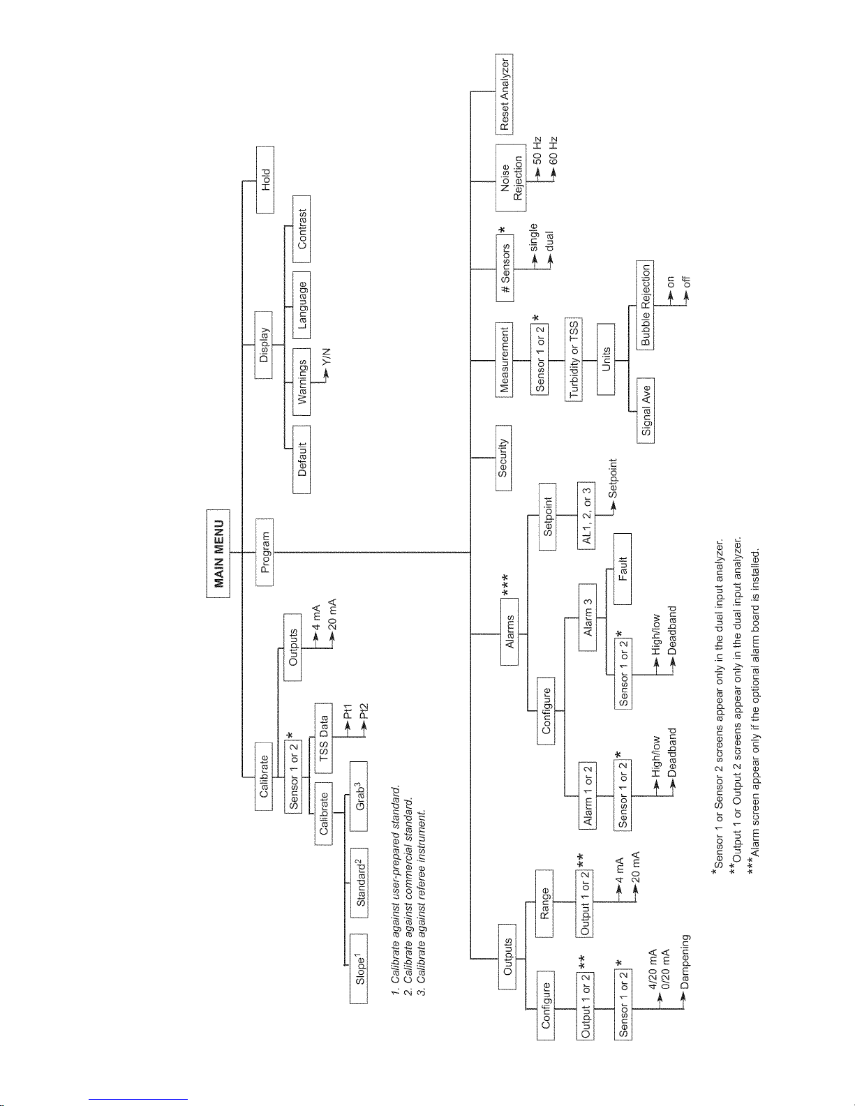
QUICK REFERENCE GUIDE
MENU TREE FOR TURBIDITY/TSS MEASUREMENTS
Page 6

About This Document
This manual contains instructions for installation and operation of the Clarity II Model
T1055 Turbidimeter.
The following list provides notes concerning all revisions of this document.
Rev
. Level
Date Notes
A 5/04 This is the CD-launch version containing only installation
information.
B 6/04 This is the electronic launch version, which added more detail
instructions for programming and troubleshooting.
C 11/04 This is the initial full release of the product manual. The manual
has been reformatted to reflect the Emerson documentation
style and updated to reflect any changes in the product offering.
D 1/05 Updated ordering matrix, added lamp calibration section,
revised information screens section.
E 3/05 Revised panel mount drawing.
F 7/05 Revised text on pp. 32 & 34; revised text & figure on page 46.
G 10/05 Revised text on pp 9 & 47 and drawings on pp. 10 & 48 to
show new molded debubbler; revised debubbler specifications.
Addition of agency-required warnings to pp. 12, 43, 45, & 48.
H 1/06 Revised Analyzer Enclosure Specifications - page 2.
I 2/06 Added FM and CSA Non-Incendive approval ratings to
Specifications - Analyzer, page 2.
Added FM and CSA Non-Incendive installation control drawings
to section 3.0 - Wiring, pp. 12-15.
Page 7

i
MODEL CLARITY II TABLE OF CONTENTS
MODEL CLARITY II TURBIDIMETER
TABLE OF CONTENTS
Section Title Page
1.0 DESCRIPTION AND SPECIFICATIONS .............................................................................. 1
1.1 Features and Applications...................................................................................................... 1
1.2 Specifications ......................................................................................................................... 2
2.0 INSTALLATION...................................................................................................................... 3
2.1 Unpacking and Inspection ...................................................................................................... 3
2.2 Installation — Analyzer........................................................................................................... 3
2.3 Installation — Flow Chamber and Debubbler......................................................................... 7
2.4 Installation — Sensor ............................................................................................................. 9
2.5 Sample Point .......................................................................................................................... 9
3.0 WIRING .................................................................................................................................. 10
3.1 Preparing Conduit Openings .................................................................................................. 10
3.2 Power, Alarm, Output, and Sensor Connections ................................................................... 10
3.3 Non-Incendive Installation Control Drawings ......................................................................... 12
4.0 DISPLAY AND OPERATION ................................................................................................. 16
4.1 Display.................................................................................................................................... 16
4.2 Keypad ................................................................................................................................... 16
4.3 Programming and Calibrating the Solu Comp II - Tutorial...................................................... 17
4.4 Security .................................................................................................................................. 18
4.5 Using Hold.............................................................................................................................. 18
5.0 PROGRAMMING THE ANALYZER....................................................................................... 19
5.1 General................................................................................................................................... 19
5.2 Changing StartUp Settings..................................................................................................... 19
5.3 Configuring and Ranging the Outputs .................................................................................... 22
5.4 Configuring Alarms and Assigning Setpoints.......................................................................... 23
5.5 Choosing Turbidity or Total Suspended Solids ....................................................................... 26
5.6 Choosing Single Sensor or Dual Sensor Input....................................................................... 29
5.7 Setting a Security Code.......................................................................................................... 30
5.8 Noise Rejection ...................................................................................................................... 30
5.9 Resetting Factory Default Settings......................................................................................... 31
5.10 Selecting a Default Screen, Language, and Screen Contrast................................................ 32
6.0 CALIBRATION ....................................................................................................................... 34
6.1 Introduction............................................................................................................................. 34
6.2 Calibrating Against a User-Prepared Standard ...................................................................... 34
6.3 Calibrating Against a Commercial Standard........................................................................... 37
6.4 Calibrating the Turbidity Sensor Against a Grab Sample ....................................................... 39
6.5 Lamp Calibration .................................................................................................................... 41
6.6 Using the Dry Check Standard............................................................................................... 42
6.7 Entering a Turbidity to TSS Conversion Equation.................................................................. 43
6.8 Calibrating Current Outputs.................................................................................................... 45
7.0 MAINTENANCE .................................................................................................................... 46
7.1 SoluComp II Analyzer............................................................................................................. 46
7.2 Sensor .................................................................................................................................... 48
7.3 Debubbler and Measuring Chamber ...................................................................................... 49
7.4 List of Replacement Parts ...................................................................................................... 50
8.0 TROUBLESHOOTING........................................................................................................... 51
8.1 Overview ................................................................................................................................ 51
8.2 Troubleshooting Using Fault Codes ....................................................................................... 51
8.3 Troubleshooting Calibration Problems ................................................................................... 53
8.4 Troubleshooting Other Problems............................................................................................ 54
8.5 Information Screens ............................................................................................................... 56
9.0 RETURN OF MATERIAL ...................................................................................................... 58
Page 8

MODEL CLARITY II TABLE OF CONTENTS
LIST OF FIGURES
Number Title Page
2-1 Panel Mount Installation ........................................................................................... 4
2-2 Pipe Mount Installation ............................................................................................. 5
2-3 Surface Mount Installation........................................................................................ 6
2-4 Opening the Supporting Clamps .............................................................................. 7
2-5 Debubbler and Flow Chamber ................................................................................. 7
2-6 Sensor ...................................................................................................................... 9
2-7 Sampling for Turbidity............................................................................................... 9
3-1 Removing the Knockouts ......................................................................................... 10
3-2 Wiring Diagram for Model T1055-10 analyzer (panel mount version)...................... 10
3-3 Wiring Diagram for Model T1055-11 analyzer (wall/pipe mount version) ................. 10
3-4 Non-Incendive Field Wiring (FM) T1055-10 ............................................................. 12
3-5 Non-Incendive Field Wiring (FM) T1055-11.............................................................. 13
3-6 Non-Incendive Field Wiring (CSA) T1055-10 ........................................................... 14
3-7 Non-Incendive Field Wiring (CSA) T1055-11 ........................................................... 15
4-1 Displays During Normal Operation........................................................................... 16
4-2 Solu Comp II Keypad ............................................................................................... 16
5-1 Assigning Outputs 1 and 2 in a dual input instrument ............................................. 17
5-2 High Alarm Logic ..................................................................................................... 19
5-3 Low Alarm Logic ....................................................................................................... 19
5-4 Turbidity Sensor — General..................................................................................... 22
5-5 Turbidity Sensor — EPA 180.1................................................................................. 22
5-6 Turbidity Sensor — ISO 7027................................................................................... 23
6-1 Calibration Against a User-Prepared Standard ........................................................ 30
6-2 Converting Turbidity to TSS ..................................................................................... 39
6-3 Lowest Turbidity (TSS) ............................................................................................. 39
7-1 Exploded View of Solu Comp II (Panel Mount Version) ........................................... 42
7-2 Exploded View of Solu Comp II (Pipe/Surface Mount Version) ................................ 43
7-3 Replacing the Lamp/LED Board............................................................................... 44
LIST OF TABLES
Number Title Page
5-1 Default Settings ........................................................................................................ 20
7-1 Replacement Parts for Solu Comp II (Panel Mount Version) ................................... 46
7-2 Replacement Parts for Solu Comp II (Pipe/Surface Mount Version) ........................ 47
APPENDIX
APPENDIX .............................................................................................................. 59
ii
Page 9

1
MODEL CLARITY II SECTION 1.0
DESCRIPTION AND SPECIFICATIONS
SECTION 1.0.
DESCRIPTION AND SPECIFICATIONS
• COMPLETE SYSTEM includes single or dual input analyzer, sensor(s), and debubbler assembly
• CHOOSE U.S. EPA METHOD 180.1 or ISO METHOD 7027 compliant sensors
• RANGE 0-200 NTU
• RESOLUTION 0.001 NTU
• FULL FEATURED ANALYZER with fully scalable analog outputs and optional fully
programmable alarms
• INTUITIVE, USER-FRIENDLY MENU in six languages makes setup and calibration
easy
Clarity II is a trademark of Emerson Process Management.
FEATURES AND APPLICATIONS
The Clarity II turbidimeter is intended for the determination of turbidity in water. Low stray light, high stability, efficient bubble rejection, and a display resolution of
0.001 NTU make Clarity II ideal for monitoring the tur-
bidity of filtered drinking water. Because it measures
turbidity as high as 200 NTU, Clarity II is also suitable
for most raw waters. The Clarity II turbidimeter can be
used in applications other than drinking water treatment. Examples are monitoring wastewater discharges, condensate returns, and clarifiers.
Both USEPA 180.1 and ISO 7027-compliant sensors
are available. USEPA 180.1 sensors use a visible light
source. ISO 7027 sensors use a near infrared LED.
For regulatory monitoring in the United States, USEPA
180.1 sensors must be used. Regulatory agencies in
other countries may have different requirements.
The Clarity II turbidimeter consists of an analyzer,
which accepts either one or two sensors, the sensors
themselves, and a debubbler/measuring chamber and
cable for each sensor. The cable plugs into the sensor
and the analyzer, making setup fast and easy. Sensors
can be located as far as 50 ft (15.2 m) away from the
analyzer.
The Clarity II turbidimeter incorporates the popular
and easy to use Solu Comp II analyzer. Menu flows
and prompts are so intuitive that a manual is practically not needed. Analog outputs are fully scalable. An
optional alarm board with three relays is also available. Alarms are fully programmable for high/low logic
and dead band. To simplify programming, the analyzer
automatically detects whether an EPA 180.1 or ISO
7027 sensor is being used.
Clarity II is available in an optional configuration in
which the analyzer, sensor(s), and debubbling flow
cell(s) are mounted on a single back plate. The sensor
cables are pre-wired to the analyzer, so setup is
exceptionally fast and easy. All the user does is mount
the unit on a wall, bring in power and sample, and provide a drain. To order this option, consult the factory.
A dry check is also available to periodically confirm
Clarity II operation.
Page 10
2
MODEL CLARITY II SECTION 1.0
DESCRIPTION AND SPECIFICATIONS
1.2 SPECIFICATIONS — ANALYZER
Enclosure: ABS (panel mount), polycarbonate (pipe/wall
mount); NEMA 4X/CSA 4 (IP65)
Dimensions:
Panel mount version: 6.10 X 6.10 X 3.72 in (155 X 155 X
94.5 mm)
Pipe/ Wall mount version: 6.23 X 6.23 X 3.23 in (158 X 158 X
82 mm)
Conduit openings: Accepts PG 13.5 or ½-in fittings.
Display: Two line, 16-character back lit display. Character
height 4.8 mm. Display can be customized to meet individual requirements.
Security Code: 3-digit code prevents accidental or unautho-
rized changes in instrument settings and
calibration.
Languages: English, German, Spanish, Italian, French,
Portuguese
Units: Turbidity (NTU, FTU, or FNU); total suspended solids
(mg/L, ppm, or no units)
Display resolution-turbidity: 4 digits; decimal point moves
from x.xxx to xxx.x
Display resolution-TSS: 4 digits; decimal point moves from
x.xxx to xxxx
Calibration methods: user-prepared standard, commercially
prepared standard, or grab sample. For total suspended
solids user must provide a linear calibration equation.
Ambient temperature and humidity: 0 to 50°C, (32 to 122°F);
RH 10 to 90% (non-condensing)
Power: 85 to 265 Vac, 47.5 to 65.0 Hz. Maximum current with-
out option -60 alarm board: 1.0 amp, with option -60 alarm
board: 1.3 amp.
Equipment protected by double insulation.
Hazardous Location:
Class I, Div. 2, Groups A, B, C, & D: T3C Tamb 0°-50°C
Suitable for use in Class II and III, Division 2, Groups E, F
and G. Enclosure Type 4/4X
Install in accordance with control drawing
no. 1400311 or 1400312 (FM).
Install in accordance with control drawing
no. 1400313 or 1400314 (CSA).
(Ordinary Location only)
Inputs: Choice of single or dual input
RFI/EMI: EN-61326
LVD: EN-61010-1
Outputs: Single input analyzer has single output. Dual input
analyzer has dual outputs. Outputs are 0-20 mA or 4-20
mA isolated. Maximum load is 600 ohms. Output dampening with 5 sec time constant is user-selectable.
Output Accuracy: 0.05 mA
Alarms: Optional alarm relay board includes three alarms.
Alarm 3 can be configured as a fault alarm in-stead of a
process alarm. Each relay can be configured independently. Alarm logic (low or high) and dead band are user-programmable.
Relays: Form C, single pole, double throw, epoxy sealed.
Alarm Board Ratings:
Field wiring terminals: removable terminal blocks for power,
analog outputs, and sensors
SPECIFICATIONS — SENSOR
Method: EPA 180.1 or ISO 7027 (using 860 nm LED source).
Must be specified when ordering.
Incandescent lamp life: two years
LED life: five years
Wetted materials: Delrin1, glass, EPDM
Accuracy after calibration at 20.0 NTU:
0 - 1 NTU: ±2% of reading or ±0.015 NTU, whichever is
greater.
0 - 20 NTU: ±2% of reading
Cable: 20 ft (6.1 m) or 50 ft (15.2 m). Maximum 50 ft
(15.2 m). Connector is IP65.
Maximum Pressure: 30 psig (308 kPa abs)
Temperature: 40 - 95°F (5 - 35°C)
1
Delrin is a registered trademark of DuPont Performance Elastomers.
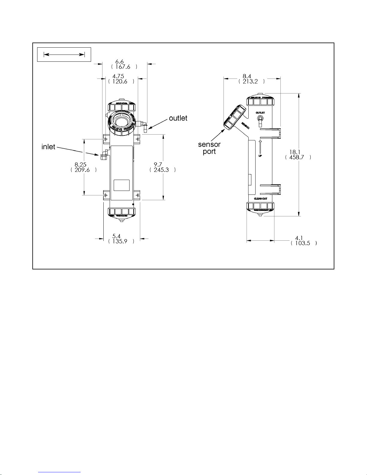
SPECIFICATIONS — DEBUBBLER AND
FLOW CHAMBER
Dimensions: 18.1 in. x 4.1 in. diam. (460 mm x 104 mm diam.)
(approx.)
Wetted materials: ABS, EPDM
Inlet: compression fitting accepts 1/4 in. OD tubing; fitting can
be removed to provide 1/4 in. FNPT
Drain: barbed fitting accepts 3/8 in. ID tubing; fitting can be
removed to provide 1/4 in. FNPT. Must drain to atmosphere.
Sample temperature: 40 - 95°F (5 - 35°C)
Minimum inlet pressure : 3.5 psig (125 kPa abs). 3.5 psig will
provide about 250 mL/min sample flow.
Maximum inlet pressure: 30 psig (308 kPa abs). Do not block
drain tube.
Recommended sample flow: 250 - 750 mL/min
Response Time: The table shows the time in minutes to per-
cent of final value following a step change in turbidity.
SPECIFICATIONS — MISCELLANEOUS
Weight/shipping weight:
Sensor: 1 lb/2 lb (0.5 kg/1.0 kg)
Analyzer: 2 lb/3 lb (1.0 kg/1.5 kg)
Debubbler: 3 lb/4 lb (1.5 kg/2.0 kg)
(rounded to the nearest lb or 0.5 kg)
Specifications subject to change without notice.
Resistive Inductive
115 Vac 5.0 A 3.0 A
230 Vac 5.0 A 1.5 A
reponse time (minutes)
% response following
4 gph 12 gph
step change
(250 mL/min) (750 mL/min)
10 2.0 0.5
50 2.5 1.0
90 4.5 2.5
99 7.0 4.0
Page 11
SECTION 2.0.
INSTALLATION
2.1 UNPACKING AND INSPECTION
The Clarity II Turbidimeter is a complete system for the determination of turbidity in drinking water. The system
consists of the analyzer, sensor(s), cable(s), and flow chamber/debubbler(s). Consult the table to verify that you
have received the parts for the option you ordered.
(1)
The analyzer model number is printed on a label attached to the side of the instrument. For example, if you
ordered a panel mount, dual input analyzer, with alarm board, the label should read: T1055-10-22-60.
2.2 INSTALLATION — ANALYZER
2.2.1 General Information
1. Although the analyzer is suitable for outdoor use, do not install it in direct sunlight or in areas of extreme temperatures.
2. Install the analyzer in an area where vibrations and electromagnetic and radio frequency interference are minimized or absent.
3. Keep the analyzer and sensor wiring at least one foot from high voltage conductors. Be sure there is easy
access to the analyzer.
4. Do not run AC power and relay wiring through the top conduit openings. Keep AC power and relay
wiring separate from other wiring in the analyzer after installation.
5. The analyzer is suitable for panel, pipe, or surface mounting. Refer to the table below.
6. See Section 3.1 for removal of conduit knockouts.
7. To reduce the likelihood of stress on wiring connections, remove the hinged front panel (-11 models) from the
base during wiring installation. Allow sufficient wire length to avoid stress on conductors.
Item Model/part number
(1)
Analyzer-panel mount
(1)
T1055-[10]-[ ]
Analyzer-pipe/wall mount T1055-[11]-[ ]
Analyzer-single input T1055-[ ]-[21]
Analyzer-dual input T1055-[ ]-[22]
Analyzer- alarm board input T1055-[ ]-[ ]-[60]
Sensor-EPA standard 8-0108-0002-EPA
Sensor-ISO standard 8-0108-0003-ISO
Cable-3 ft (0.9 m) 24138-00
Cable-20 ft (6.1 m) 24097-00
Cable-50 ft (15.2 m) 24098-00
Calibration cup 24101-00
Molded chamber/debubbler 24170-00
Type of Mounting Section
Panel 2.2.2
Pipe 2.2.3
Surface 2.2.4
MODEL CLARITY II SECTION 2.0
INSTALLATION
3
Page 12
4
MODEL CLARITY II SECTION 2.0
INSTALLATION
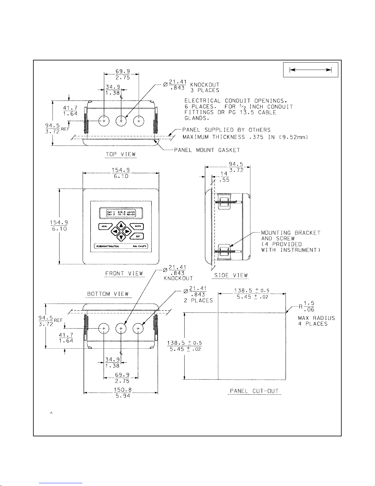
FIGURE 2-1. Panel Mount Installation
Access to the wiring terminals is through the rear cover. Four screws hold the cover in place.
2.2.2 Panel Mounting.
MILLIMETER
INCH
Page 13
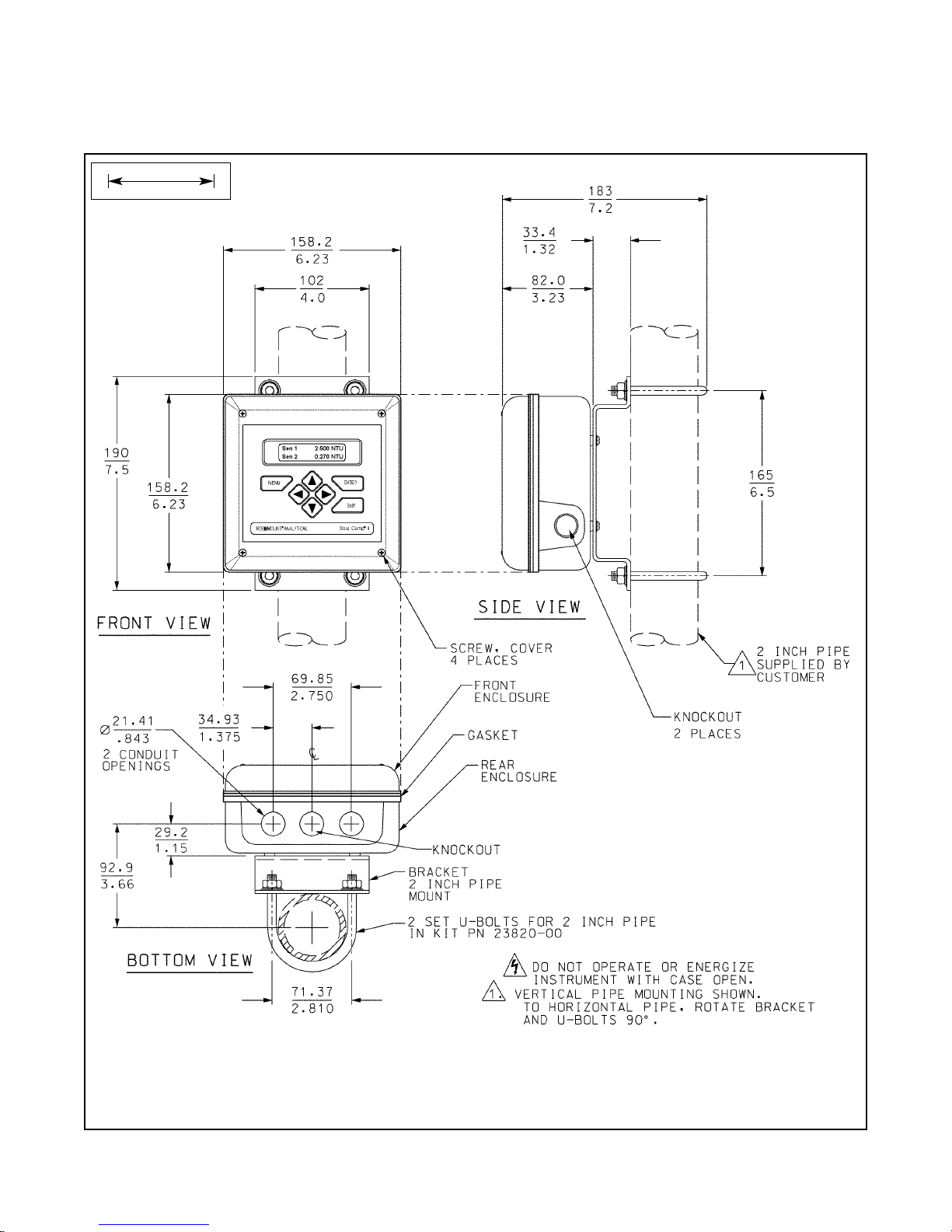
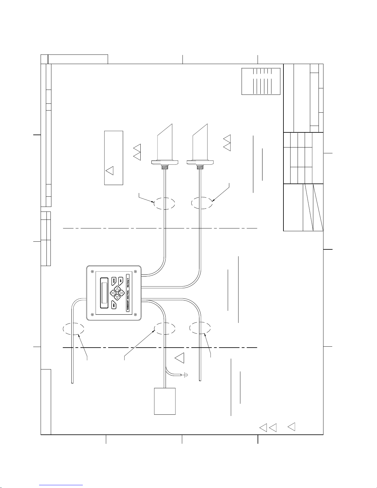
FIGURE 2-2. Pipe Mount Installation
The front panel is hinged at the bottom. The panel swings down for access to the wiring terminals.
2.2.3 Pipe Mounting.
MILLIMETER
INCH
MODEL CLARITY II SECTION 2.0
INSTALLATION
5
Page 14
6
MODEL CLARITY II SECTION 2.0
INSTALLATION
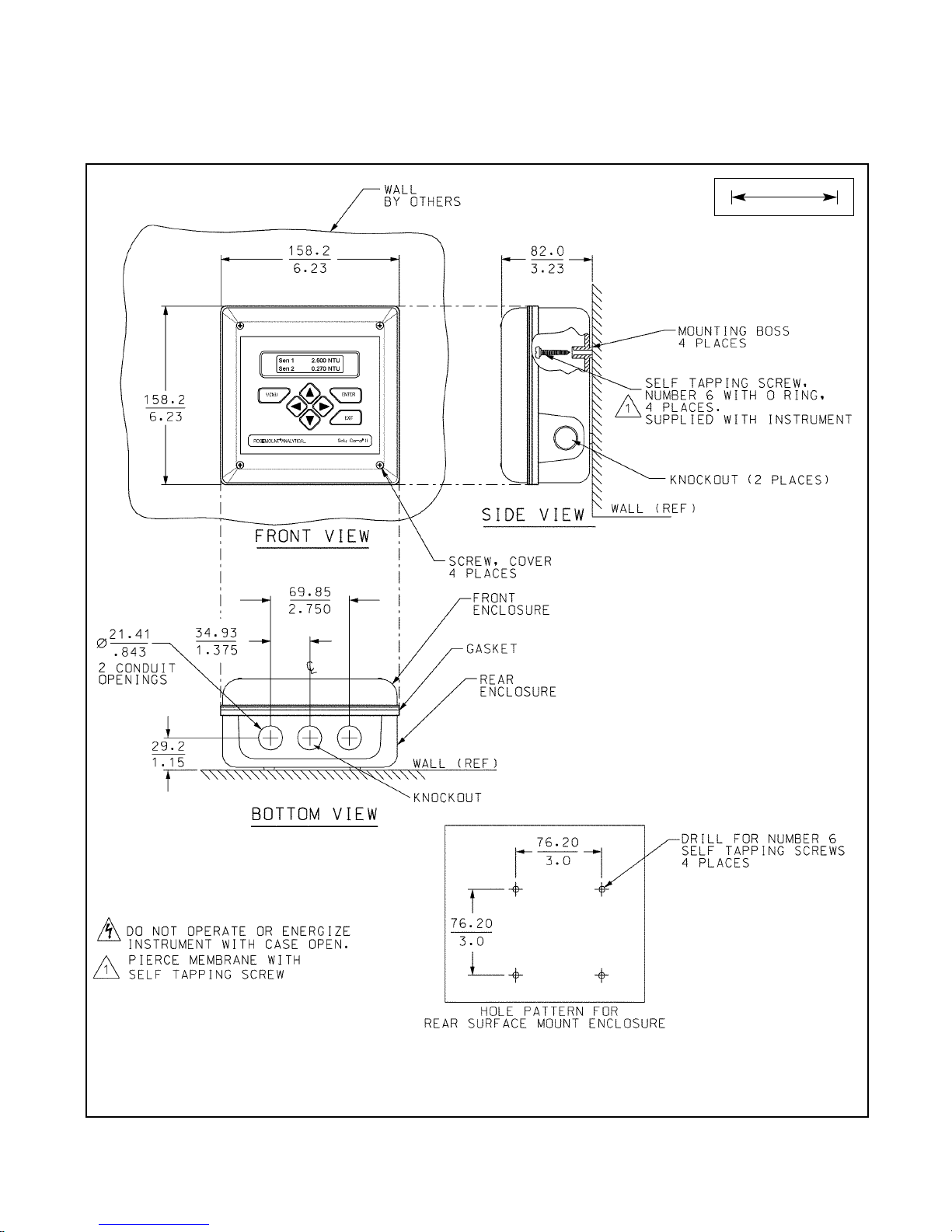
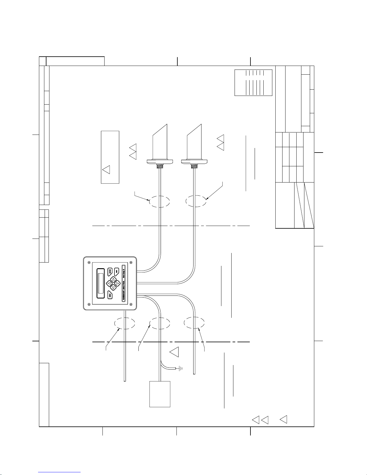
FIGURE 2-3. Surface Mount Installation
The front panel is hinged at the bottom. The panel swings down for access to the wiring terminals.
2.2.4 Surface Mounting.
MILLIMETER
INCH
Page 15
2.3 INSTALLATION — DEBUBBLER ASSEMBLY
See Figure 2-4 for installation.
Connect the sample line to the inlet fitting. The fitting accepts 1/4-inch OD tubing. See Section 2.6 for recommended installation of the sample port.
Attach a piece of 3/8 inch ID soft tubing to the drain fitting. The debubbler must drain to atmosphere.
NOTE
During operation, the debubbler is under pressure. A 0.040 inch (1 mm) orifice in the outlet provides the pressure. Back pressure helps prevent outgassing, which can lead to bubbles accumulating on the sensor face resulting in erroneous readings. DO NOT EXCEED 30 psig (308
kPa abs) inlet pressure.
The amount of pressure in the debubbler can be estimated from the flow rate. See Table 2-1.
To control and monitor sample flow, a valved rotameter with fittings is available (PN 24103-00). Attach the
rotameter to the debubbler outlet. The rotameter can also be used to increase back pressure on the debubbler if
additional pressure is needed to prevent outgassing.
MODEL CLARITY II SECTION 2.0
INSTALLATION
CAUTION
BEFORE REMOVING THE SENSOR, be absolutely
certain the process pressure is reduced to 0 psig
and the process temperature is at a safe level.
TABLE 2-1. Approximate debubbler pressure
as a function of flow (0.040 inch outlet orifice)
gph psig
21
43
68
814
10 21
11 26
12 31
——
mL/min kPa abs
100 110
200 120
300 140
400 160
500 190
600 240
700 280
800 340
7
Page 16
8
FIGURE 2-4. Debubbler and Flow Chamber
INCH
MILLIMETER
MODEL CLARITY II SECTION 2.0
INSTALLATION
Page 17
9
2.4 INSTALLATION — SENSOR
Unscrew the nut on the side of the debubbler. Insert the sensor in the mouth of the measuring chamber. Be sure
the pin on the debubbler lines up with the hole in the sensor. Replace the nut. Remove the protective cap from
the sensor and screw the cable onto the receptacle. The plug and receptacle are keyed for proper alignment.
2.5 SAMPLE POINT
Locate the sample tap to minimize pickup of sediment or air. See Figure 2-6. If possible, install a sampling port
that extends one or two inches (25 - 50 mm) into the pipe. Use ¼ inch OD rigid plastic tubing. Avoid soft plastic
tubing if possible. To reduce sample lag time, install the debubbler and flow chamber as close to the sample tap
as possible.
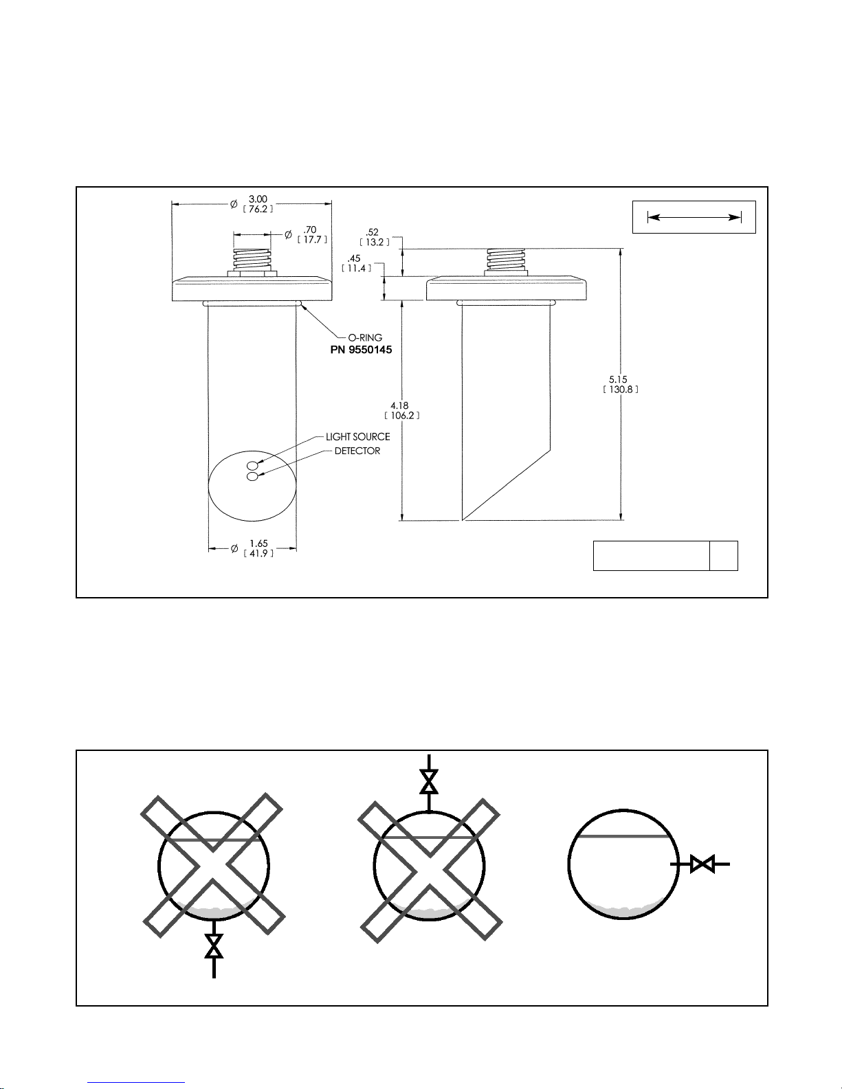
FIGURE 2-6. Sampling for Turbidity
FIGURE 2-5. Sensor
INCH
MILLIMETER
DWG. NO. REV.
40T105501 A
MODEL CLARITY II SECTION 2.0
INSTALLATION
Page 18
1010
MODEL CLARITY II SECTION 3.0
WIRING
SECTION 3.0.
WIRING
3.1 PREPARING CONDUIT OPENINGS
The analyzer enclosure has five conduit openings. Two are
open and three are knockouts.
Conduit openings accept 1/2-inch conduit fittings or PG 13.5
cable glands. To keep the case watertight, block unused
openings with NEMA 4X or IP65 conduit plugs.
NOTE
Use watertight fittings and hubs that comply with the
requirements of UL514B. Connect the conduit hub to the
conduit before attaching the fitting to the analyzer
(UL508-26.16).
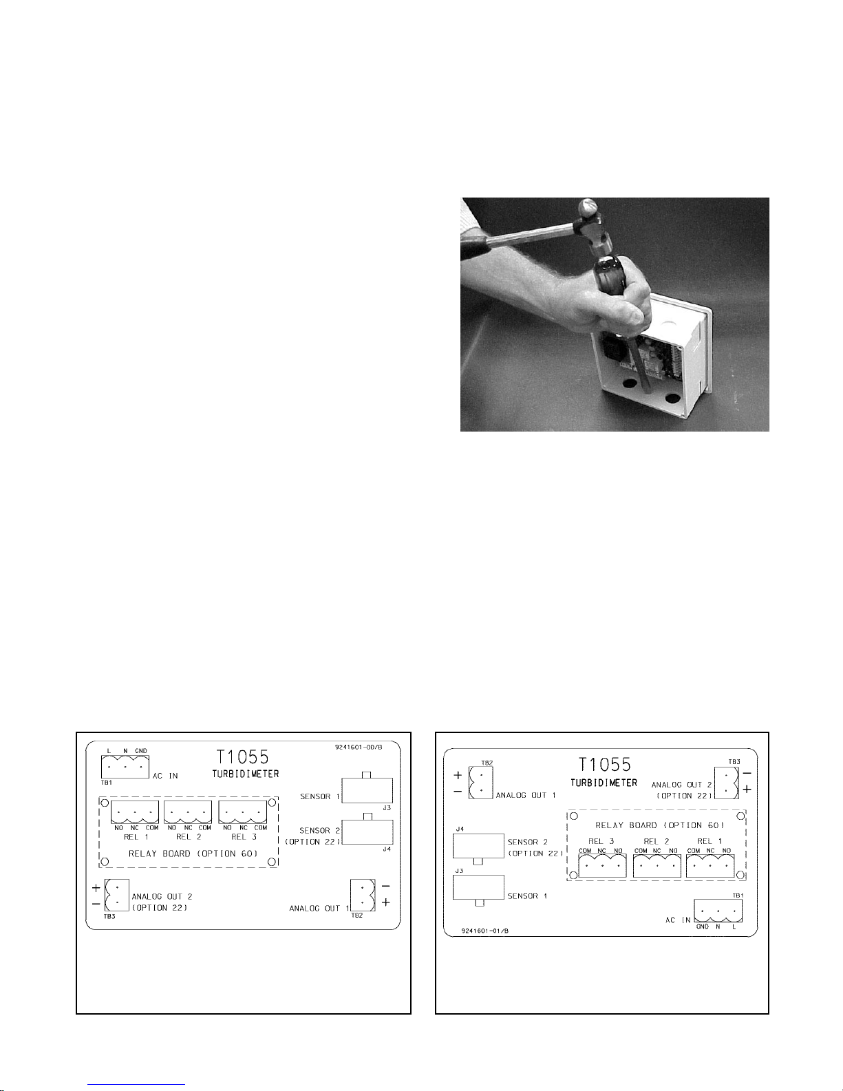
Figure 3-1 shows how to remove the knockouts. The knockout grooves are on the outside of the case. Place the screwdriver blade on the inside of the case and align it approximately along the groove. Rap the screwdriver sharply with a
hammer until the groove cracks. Move the screwdriver to an uncracked portion of the groove and continue the
process until the knockout falls out. Use a small knife blade to remove the flash from the inside of the hole.
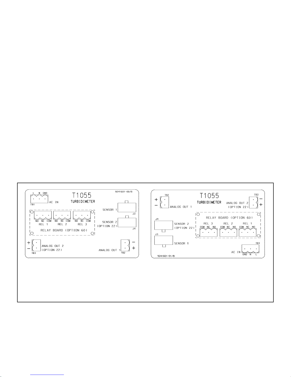
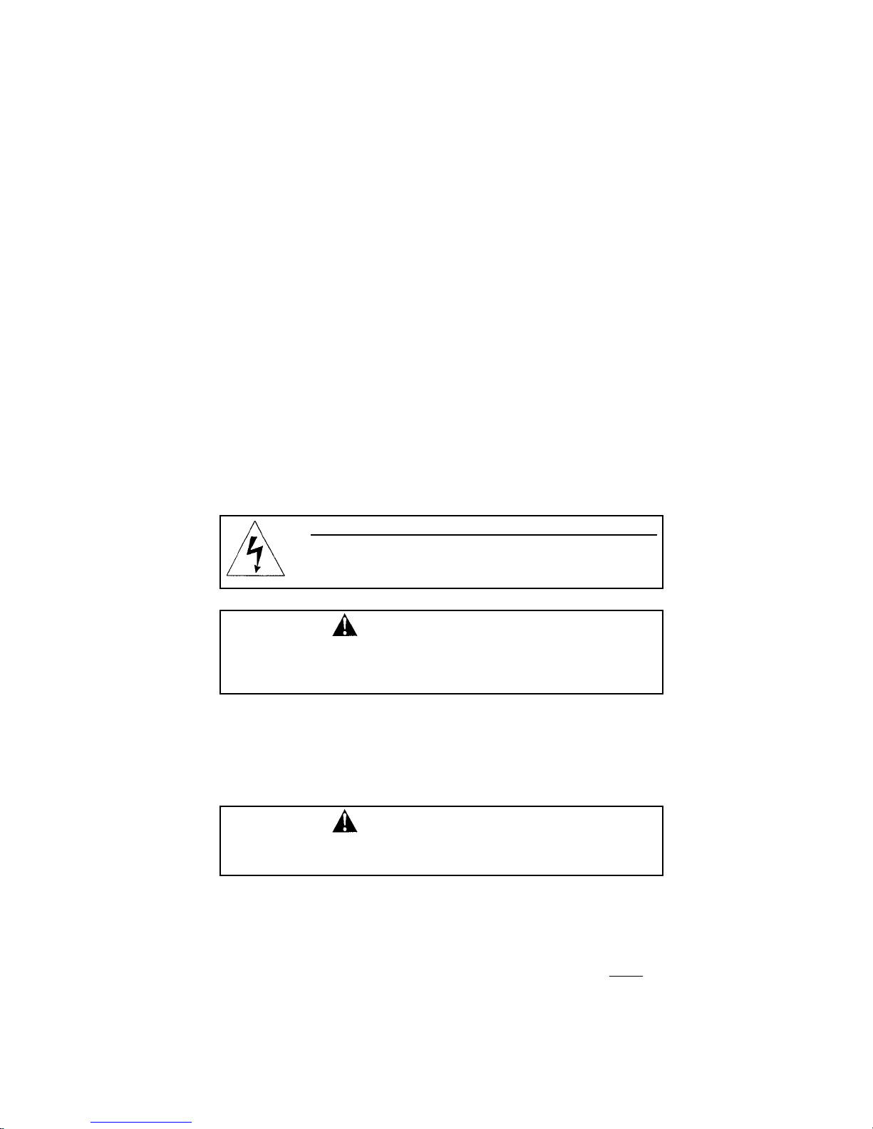
3.2 POWER, ALARM, OUTPUT, AND SENSOR CONNECTIONS
3.2.1 General Information
The analyzer is available in two mounting configurations.The positions of the power, alarm, output, and sensor terminal blocks are different in each. See Figure 3-2 (panel mount) or Figure 3-3 (pipe/wall mount).
To reduce the likelihood of stress on wiring connections, keep the hinged front panel (-11 option only) attached to
the back cover while installing wiring. Be sure there is sufficient cable within the analyzer enclosure to avoid stress
on conductors and connections.
For ease of wiring, connections for power, outputs, and alarms are removable.
FIGURE 3-1. Removing the Knockouts
FIGURE 3-2. Wiring Diagram for Model T1055-10
analyzer (panel mount version)
The release clip on the sensor plug faces
the top of the analyzer enclosure.
FIGURE 3-3. Wiring Diagram for Model T1055-11
analyzer (wall/pipe mount version)
The release clip on the sensor plug faces the user.
Page 19
3.2.2 Sensor
The sensor cable is pre-wired to a plug that inserts into a receiving socket in the analyzer. See Figures 3-2 and
3-3 for the locations of the sockets. If you are using a single input analyzer, be sure to plug the sensor into the
SENSOR 1 receptacle. The cable also passes through a strain relief fitting. To install the cable…
1. Remove the wrenching nut from the strain relief fitting.
2. Insert the plug through the hole in the bottom of the enclosure nearest the sensor socket. Seat the fitting in the
hole.
3. Slide the wrenching nut over the cable plug and screw it onto the fitting.
4. Loosen the cable nut so the cable slides easily.
5. Insert the plug into the appropriate receptacle. To remove the plug, squeeze the release clip and pull straight
out.
6. Adjust the cable slack in the enclosure and tighten the cable nut. Be sure to allow sufficient slack to avoid placing stress on the cable and connections.
7. Plug the cable into the back of the sensor.
8. Place the sensor in either the measuring chamber or the calibration cup. The sensor must be in a dark place
when power is first appled to the analyzer.
3.2.3 Power, Alarm, and Ouput
AC wiring should be 14 gauge or greater. Provide a switch or breaker to disconnect the analyzer from the main
power supply. Install the switch or breaker near the analyzer and label it as the disconnecting device for the
analyzer.
Keep sensor and output signal wiring separate from power wiring. Do not run sensor and power wiring in the same
conduit or close together in a cable tray.
For best EMI/RFI protection use shielded output signal cable enclosed in an earth-grounded metal conduit.
Connect the shield to earth ground.
Do not apply power to the analyzer until all connections are secured and verified.
3.2.4
The sensor cable is rated as Non-Incendive field wiring by FM and CSA.
The AC power wiring, analog output wiring, and alarm wiring (optional configuration) is not
rated as Non-Incendive
and must be installed in metal conduit. Refer to the FM and CSA control drawings herein, Figures 3-4 through 3-7, for
proper installation in hazardous areas.
WARNING: RISK OF ELECTRICAL SHOCK
AC connections and grounding must be in compliance with UL
508 or local electrical code. DO NOT apply power to the analyzer until all electrical connections are verified and secure.
MODEL CLARITY II SECTION 3.0
WIRING
WARNING!
Explosion hazard. Do not disconnect equipment when a flammable or
combustible atmosphere is present.
WARNING!
Exposure to some chemicals may degrade the sealing properties of
materials used in the following device: PN AZ8-1CH-6DSEA (Zettler
Inc.)
11
Page 20
12
MODEL CLARITY II SECTION 3.0
WIRING
FIGURE 3-4. Non-Incendive Field Wiring (FM) T1055-10
1400311
C
CHECKED/APPROVED
DATE
1
BY
REVISION
WARNING
!
2
LTR ECO DESCRIPTION
PROCESS MEDIA ONLY
FOR USE W IT H NON-FLAMMABLE
C
TURBIDITY
CLARITY II
SENSOR #2
(OPTIONAL)
6
5
TURBIDITY
CLARITY II
B
REV
REV
REV
REV
REV
REV
FM C
THIS DOCUMENT IS
CERTIFIED BY
SENSOR #1
6
5
AREA
SENSOR CABLE
IS SHIELDED
SENSOR CABLE
IS SHIE LDED
UNCLASSIFIED
A
C
REV
ANALYTICAL
ROSEMOUNT
W/O AGENCY APPROVAL
REVISIONS NOT PERMITTED
T1055-10
SHEET 1 OF 1
12
1400311
NON INCENDIVE FIELD
Emerson
PROCESS MAN A GE M EN T
TITLE
DATE
1/5/05
12/7/04
B. JOHNSON
J. FLOCK
APPROVALS
DRAWN
CHECKED
NONE
DWG NO
WIRING INSTALLATION (FM)
SIZE
SCALE: WEIGHT:
C
1/5/05
J. FLOCK
THIS FILE CREATED USING
SOLID EDGE
ENG APVD
C9160
REV
ECO NORELEASE DATE
AUG 1, 2005
WIRING (VAC)
(OPTIONAL)
T1055-10
CLAS S II, III, DIV 2, G PS E-G
HAZARDOU S AREA
CLASS I, DIV. 2, GPS A-D, 0 - 50 C
3
ALARM
ANGLES – 1/2.
.XX – .03 .XXX – .010
DIMENSIONS ARE IN INCHES
NOMINAL SURFACE FINISH: 125
MACHINE FILLET RADII .020 MAX
REMOVE BURRS & SHARP EDGES
FINISH
MATERIAL
3
NEC (ANSI-NFPA 70 )
3
ANALOG OUTPUT
4
METAL CONDUIT
METAL CONDUIT
VAC
115/230
POWER SUPPLY
METAL CO N DUIT
AREA
4
UNCLASSIFIED
Rosemount Analytical, and is not to be made available
to those who may compete with Rosemount Analytical.
This document contains information proprietary to
D
C
3 GROUND CONNECT ION MA Y BE MAD E IN HAZARDOUS A REA.
2. SEAL REQUIRED AT EACH C ONDUIT ENTRANCE.
6 NON INCENDIVE FIELD WIRING IS ALLOWED.
5 MAX CABLE LENGT H IS 50 FEET.
4. NO REVISION TO DRAWING WITHOUT FM APPROVAL.
B
A
1. INSTALLATION MUST CONFORM TO THE
NOTES: UNLESS OTHERWISE SPECIFIED
Page 21
MODEL CLARITY II SECTION 3.0
WIRING
13
FIGURE 3-5. Non-Incendive Field Wiring (FM) T1055-11
1400312
C
CHECKED/APPROVED
DATE
1
BY
REVISION
C
TURBIDITY
CLARITY II
SENSOR #2
(OPTIONAL)
6
5
TURBIDITY
CLARITY II
B
C
REV
REV
REV
REV
REV
REV
FM
THIS DOCUMENT IS
CERTIFIED BY
SENSOR #1
6
5
WARNING
!
2
PROCESS MEDIA ONLY
FOR USE W IT H NON-FLAMMABLE
SENSOR CABLE
IS SHIE LDED
SENSOR CABLE
IS SHIELDED
AREA
UNCLASSIFIED
A
REV
C
ANALYTICAL
ROSEMOUNT
W/O AGENCY APPROVAL
REVISIONS NOT PERMITTED
T1055-11
SHEET 1 OF 1
12
1400312
NON INCENDIVE FIELD
Emerson
PROCESS MAN A GE M EN T
TITLE
DATE
1/5/05
12/8/04
B. JOHNSON
J. FLOCK
APPROVALS
DRAWN
CHECKED
NONE
DWG NO
WIRING INSTALLATION (FM)
SIZE
SCALE: WEIGHT:
C
1/5/05
J. FLOCK
THIS FILE CREATED USING
SOLID EDGE
ENG APVD
LTR ECO DESCRIPTION
ANGLES – 1/2.
.XX – .03 .XXX – .010
DIMENSIONS ARE IN INCHES
NOMINAL SURFACE FINISH: 125
MACHINE FILLET RADII .020 MAX
REMOVE BURRS & SHARP EDGES
FINISH
MATERIAL
ECO NORELEASE DATE
C9160
REV
AUG 1, 2005
3
WIRING (VAC)
(OPTIONAL)
T1055-11
CLAS S II, III, DIV 2, G PS E-G
HAZARDOU S AREA
CLASS I, DIV. 2, GPS A-D, 0 - 50 C
NEC (ANSI-NFPA 70 )
3
ALARM
3
ANALOG OUTPUT
METAL CONDUIT
4
Rosemount Analytical, and is not to be made available
to those who may compete with Rosemount Analytical.
This document contains information proprietary to
D
METAL CONDUIT
VAC
115/230
POWER SUPPLY
C
METAL CO N DUIT
AREA
4
UNCLASSIFIED
3 GROUND CONNECT ION MA Y BE MAD E IN HAZARDOUS A REA.
2. SEAL REQUIRED AT EACH C ONDUIT ENTRANCE.
6 NON INCENDIVE FIELD WIRING IS ALLOWED.
5 MAX CABLE LENGT H IS 50 FEET.
4. NO REVISION TO DRAWING WITHOUT FM APPROVAL.
B
A
1. INSTALLATION MUST CONFORM TO THE
NOTES: UNLESS OTHERWISE SPECIFIED
Page 22

14
MODEL CLARITY II SECTION 3.0
WIRING
3
FIGURE 3-6. Non-Incendive Field Wiring (CSA) T1055-10
1400313
C
CHECKED/APPROVED
DATE
1
BY
C
B
REV
REV
REV
REV
REV
REV
CSA C
THIS DOCUMENT IS
CERTIFIED BY
TURBIDITY
CLARITY II
SENSOR #2
(OPTIONAL)
TURBIDITY
CLARITY II
SENSOR #1
A
C
REV
ANALYTICAL
ROSEMOUNT
W/O AGENCY APPROVAL
REVISIONS NOT PERMITTED
T1055-10
SHEET 1 OF 1
12
1400313
NON IN CENDIVE FIELD
Emerson
PROCESS MAN A GE M EN T
TITLE
NONE
DWG NO
WIRING INSTALLATION (CSA)
SIZE
SCALE: WEIGHT:
C
REVISION
WARNING
!
2
LTR ECO DESCRIPTION
C9160
REV
ECO NORELEASE DATE
AUG 1, 2005
PROCESS MEDIA ONLY
FOR USE W IT H NON-FLAMMABLE
5
NON INCENDIVE
FIELD WIRING
ALLOWED
4
3
ALARM
WIRING (VAC)
5
NON INCENDIVE
T1055-10
(OPTIONAL)
FIELD WIRING
HAZARDOU S AREA
AREA
ALLOWED
UNCLASSIFIED
CLAS S II, III, DIV 2, G PS E-G
CLASS I, DIV. 2, GPS A-D, 0 - 50 C
DATE
APPROVALS
DIMENSIONS ARE IN INCHES
REMOVE BURRS & SHARP EDGES
1/5/05
1/5/05
12/8/04
B. JOHNSON
J. FLOCK
J. FLOCK
THIS FILE CREATED USING
DRAWN
ANGLES – 1/2.
NOMINAL SUR FACE FINISH: 125
MACHINE FILLET RADII .020 MAX
SOLID EDGE
ENG APVD
CHECKED
.XX – .03 .XXX – .010
FINISH
MATERIAL
METAL CONDUIT
4
Rosemount Analytical, and is not to be made available
to those who may compete with Rosemount Analytical.
This document contains information proprietary to
ANALOG OUTPUT
D
3
METAL CO NDUIT
VAC
115/230
POWER SUPPLY
C
METAL CO NDUIT
AREA
4
UNCLASSIFIED
5 MAX CABLE LENGTH IS 50 FEET.
4 DURING INSTALLATION, LEAVE MAXIMUM AMOUNT OF JACKET INSULATION POSSIBLE ON N.I. FIELD
B
3 GROUND CONNECTIO N MA Y BE MADE IN HAZARDOUS AREA.
2. SEAL REQUIRED AT EACH CONDUIT ENTRANCE.
WIRING WITHIN INSTRUMENT ENCLO SURE. AFTER TERMINATION, WRAP N.I. FIELD WIRING WITHIN
ENCLOSURE WITH MYLAR TAPE, TO ENSURE ADEQUATE DOUBLE INSULATION REMAINS.
1. INSTALLATION MUST CONFORM TO THE C EC .
NOTES: UNLESS OTHERWISE SPECIFIED
A
Page 23

MODEL CLARITY II SECTION 3.0
WIRING
1
2
3
4
3
15
FIGURE 3-7. Non-Incendive Field Wiring (CSA) T1055-11
1400314
C
CHECKED/APPROVED
DATE
BY
C
B
C
REV
REV
REV
REV
REV
REV
CSA
THIS DOCUMENT IS
CERTIFIED BY
TURBIDITY
CLARITY II
SENSOR #2
(OPTIONAL)
TURBIDITY
CLARITY II
SENSOR #1
REVISION
5
WARNING
!
PROCESS MEDIA ONLY
FOR USE W IT H NON-FLAMMABLE
NON INCENDIVE
FIELD WIRING
ALLOWED
LTR ECO DESCRIPTION
ECO NORELEASE DATE
C9160
REV
4
5
AREA
NON INCENDIVE
FIELD WIRING
ALLOWED
UNCLASSIFIED
A
C
REV
ANALYTICAL
ROSEMOUNT
W/O AGENCY APPROVAL
REVISIONS NOT PERMITTED
T1055-11
SHEET 1 OF 1
12
1400314
NON IN CENDIVE FIELD
Emerson
PROCESS MAN A GE M EN T
TITLE
DATE
1/5/05
12/8/04
B. JOHNSON
J. FLOCK
APPROVALS
DRAWN
CHECKED
ANGLES – 1/2.
.XX – .03 .XXX – .010
DIMENSIONS ARE IN INCHES
NOMINAL SUR FACE FINISH: 125
MACHINE FILLET RADII .020 MAX
REMOVE BURRS & SHARP EDGES
NONE
DWG NO
WIRING INSTALLATION (CSA)
SIZE
SCALE: WEIGHT:
C
1/5/05
J. FLOCK
THIS FILE CREATED USING
SOLID EDGE
ENG APVD
FINISH
MATERIAL
AUG 1, 2005
T1055-11
CLAS S II, III, DIV 2, G PS E-G
ALARM
WIRING (VAC)
(OPTIONAL)
3
ANALOG OUTPUT
METAL CONDUIT
METAL CONDUIT
VAC
115/230
POWER SUPPLY
METAL CO NDUIT
Rosemount Analytical, and is not to be made available
to those who may compete with Rosemount Analytical.
This document contains information proprietary to
D
C
HAZARDOU S AREA
CLASS I, DIV. 2, GPS A-D, 0 - 50 C
AREA
4
UNCLASSIFIED
5 MAX CABLE LENGTH IS 50 FEET.
4 DURING INSTALLATION, LEAVE MAXIMUM AMOUNT OF JACKET INSULATION POSSIBLE ON N.I. FIELD
B
3 GROUND CONNECTIO N MA Y BE MADE IN HAZARDOUS AREA.
2. SEAL REQUIRED AT EACH CONDUIT ENTRANCE.
WIRING WITHIN INSTRUMENT ENCLO SURE. AFTER TERMINATION, WRAP N.I. FIELD WIRING WITHIN
ENCLOSURE WITH MYLAR TAPE, TO ENSURE ADEQUATE DOUBLE INSULATION REMAINS.
1. INSTALLATION MUST CONFORM TO THE C EC .
NOTES: UNLESS OTHERWISE SPECIFIED
A
Page 24

16
SECTION 4.0
DISPLAY AND OPERATION
4.1. DISPLAY
The Solu Comp II analyzer provided with
the Clarity II has a two-line display. The
display can be customized to meet user
requirements (see Section 5.11). Figure
4-1 shows some of the displays available during normal operation. View A is
the default screen for a single sensor.
View B is the default screen for dual
sensors.
The Solu Comp II has information
screens that supplement the data in the
main display. Press or to view the
information screens. The last informa-
tion screen is the software version.
During calibration and programming,
key presses cause different displays to
appear. The displays are self-explanatory and guide the user step-by-step
through the procedure.
4.2 KEYPAD
Figure 4-2 shows the Solu Comp II keypad.
FIGURE 4-1. Displays During Normal Operation
Screen A shows the turbidity and current output for sensor 1. If the analyzer had been configured to measure total suspended solids (TSS), the
units displayed would be ppm or mg/L. TSS units are user-selectable.
Screen B shows the turbidity measured by sensor 1 (S1) in the first line
and the turbidity measured by sensor 2 (S2) in the second line. Although
screens A and B are probably the most useful, other displays are available.
For example, Screen C shows the TSS value on the first line and the
measured turbidity from which it was calculated on the second line.
FIGURE 4-2. Solu Comp II Keypad
Four arrow keys move the cursor around the screen. A blinking word or
numeral show the position of the cursor. The arrow keys are also used to
change the value of a numeral. Pressing ENTER stores numbers and settings and moves the display to the next screen. Pressing EXIT returns to
the previous screen without storing changes. Pressing MENU always
causes the main menu screen to appear. Pressing MENU followed by
EXIT causes the main display to appear.
MODEL CLARITY II SECTION 4.0
DISPLAY AND OPERATION
Page 25

4.3 PROGRAMMING AND CALIBRATING THE SOLU COMP II
— TUTORIAL
Setting up and calibrating the Solu Comp II analyzer is easy. The following
tutorial describes how to move around in the programming menus. For practice, the tutorial also describes how to assign turbidity values to the 4 and
20 mA outputs for sensor 1.
1. If the MENU screen (shown at the left) is not already showing, press
MENU. Calibrate is blinking, which means the cursor is on Calibrate.
2. To assign tubidity values to current outputs, the Program sub-menu must
be open. Press . The cursor moves to Program (Program blinking).
Press ENTER. Pressing ENTER opens the Program sub-menu.
3. The Program sub-menu permits the user to set outputs, alarms (option -
60 only), and a security code, as well as choose between turbidity or TSS.
When the sub-menu opens, Outputs is blinking, which means the cursor
is on Outputs. Press or (or any arrow key) to move the cursor around
the display. Move the cursor to >> and press ENTER to cause a second
screen with more program items to appear. There are three screens in the
Program menu. Pressing >> and ENTER in the third screen causes the
display to return to the first screen (Outputs, Alarms, Measurement).
4. For practice, assign turbidity values to the 4 and 20 mA outputs for sen-
sor 1. Move the cursor to Outputs and press ENTER.
5. The screen shown at left appears. The cursor is on Output Range (blink-
ing). Output range is used to assign values to the low and high current
outputs. Press ENTER.
6. For a dual input analyzer, the screen shown at left appears. The dual input
analyzer has two outputs, one for each sensor. Move the cursor to the
desired output and press ENTER. For this example, choose Output 1.
For a single input analyzer, this screen does not appear. Instead, the
screen in step 7 appears.
7. The screen shown at left appears. Out1 S1 in the top line means output
1 (Out1) is assigned to sensor 1 (S1). For a dual input analyzer, either
output can be assigned to either sensor (sensor and output assignments
are made under the Output Configure menu shown in step 5). Use the
Out1 S1 Range? screen to assign a turbidity value to the 4 mA output.
a. Use the arrow keys to change the pH to the desired value. Press
or to move the cursor from digit to digit. Press or to increase
or decrease the value of the digit. Holding or down causes the
numeral to continuously scroll up or down.
b. To move the decimal point, press or until the cursor is on the
decimal point. Press to move the decimal point to the right. Press
to move the decimal point to the left.
c. Press ENTER to store the setting.
8. The screen shown at left appears. Use this screen to assign a full scale
pH value to the 20 mA output. Use the arrow keys to change the turbidity to the desired value. Press ENTER to store the setting.
9. The screen shown at left appears. To assign turbidity values to the low
and high currents for output 2, select Output 2 and follow the prompts.
10. To return to the main menu, press MENU. To return to the main display
press MENU then EXIT, or press EXIT repeatedly until the main display
appears. To return to the previous display press EXIT.
NOTE
To store values or settings, press ENTER before pressing EXIT.
CCaalliibbrraattee
Hold
Program Display
Calibrate Hold
PPrrooggrraamm
Display
OOuuttppuuttss
Measurement >>
OOuuttppuuttss
Alarms
Measurement >>
OOuuttppuutt RRaannggee
Output Configure
Output Range?
OOuuttppuutt11
Output2
Out1 S1 Range?
4mA
00
.000NTU
Out1 S1 Range?
20mA
00
.300NTU
Output Range?
OOuuttppuutt11
Output2
OR
option -60 only
MODEL CLARITY II SECTION 4.0
DISPLAY AND OPERATION
17
Page 26

18
MODEL CLARITY II SECTION 4.0
DISPLAY AND OPERATION
1. If a security code has been programmed, pressing MENU causes the
security screen to appear.
2. Enter the three-digit security code.
3. If the entry is correct, the main menu screen appears. If the entry is incor-
rect, the Invalid Code screen appears. The Enter Security Code screen
reappears after 2 seconds.
Enter Security
Code
000000
Invalid Code
Calibrate
HHoolldd
Program Display
Hold Outputs and
Alarms?
YYeess
No
4.4 SECURITY
4.4.1 How the Security Code Works
Use the security code to prevent accidental or unwanted changes to program settings, displays, and calibration.
4.4.2 Bypassing the Security Code
Enter 555. The main menu will open.
4.4.3 Setting a Security Code
See Section 5.7.
4.5 USING HOLD
4.5.1 Purpose
The analyzer output is always proportional to measured turbidity. To prevent unwanted alarms and improper operation of control systems, place the analyzer in hold before removing the sensor for calibration and maintenance.
Be sure to remove the analyzer from hold once calibration is complete. During hold, both outputs remain at the last
value. Once in hold, the analyzer remains there indefinitely until the user
disables hold or the power to the analyzer is turned off then on again.
While in hold, the screen shown to the left appears periodically.
HHoolldd
4.5.2 Using the Hold Function
To choose a menu item, move the cursor to the item and press ENTER.
To store a number or setting, press ENTER.
1. Press MENU. The main menu screen appears. Choose Hold.
2. The Hold Outputs and Alarms ? screen appears. Choose Yes to place
the analyzer in hold. Choose No to take the analyzer out of hold.
3. The main display screen will appear.
Page 27

SECTION 5.0
PROGRAMMING THE ANALYZER
5.1 GENERAL
This section describes how to do the following:
1. configure and assign values to the current outputs
2. configure and assign setpoints to the alarm relays
3. choose turbidity or total suspended solids (TSS)
4. set a security code
5. tell the analyzer the frequency of the ac power (needed for optimum noise rejection)
6. tell the analyzer the number of sensors being used
7. reset the analyzer to factory calibration and default settings
8. select a default display screen
Default settings are shown in Table 5-1 on the following page. To change a default setting, refer to the section listed in the table. To reset default settings, see Section 5.9.
5.2 CHANGING STARTUP SETTINGS
When the Solu Comp II is powered up for the first time, startup screens appear. The screens prompt the user to
identify the number of sensors being used, the measurement (turbidity or TSS), and the units. If incorrect settings
were entered at startup, enter the correct settings now. To change the number of sensors refer to Section 5.6. To
change the measurement, refer to Section 5.5.
FOR BEST RESULTS, ENTER THE NUMBER OF SENSORS BEING USED
(SECTION 5.6) AND WHETHER TURBIDITY OR TSS IS BEING MEASURED
(SECTION 5.5) BEFORE MAKING OTHER PROGRAM SETTINGS.
MODEL CLARITY II SECTION 5.0
PROGRAMMING THE ANALYZER
19
Page 28

20
MODEL CLARITY II SECTION 5.0
PROGRAMMING THE ANALYZER
TABLE 5-1. DEFAULT SETTINGS
1. OUTPUT CONFIGURATION
5. MISCELLANEOUS SETTINGS
section
language English 5.10
hold off 4.5
security code 000 (none) 5.7
noise rejection 60 Hz 5.8
disable warnings no 5.10
4. MEASUREMENT RELATED SETTINGS
section
measurement turbidity 5.5
turbidity units NTU 5.5
TSS units ppm 5.5
signal averaging 20 sec 5.5
bubble rejection on 5.5
measurement range and units section
turbidity 0 - 2 NTU 5.3
TSS 0 - 100 ppm 5.3
2. OUTPUT RANGES
assigned to dampening mA range section
output 1 sensor 1 off 4 - 20 5.3
output 2* sensor 2 off 4 - 20 5.3
3. ALARM CONFIGURATION AND SETPOINTS
alarm
1 2 3 section
assigned to sensor 1 sensor 2* fault 5.4
high or low high high -- 5.4
deadband 0 0 -- 5.4
setpoint (turbidity)** high 2.0; low 0.0 high 2.0; low 0.0 -- 5.4
setpoint (TSS)** high 100; low 0 high 100; low 0 -- 5.4
*For a single input configuration, alarm 2 is assigned to sensor 1.
**Number assigned to setpoint is unaffected by units selected.
*Output 2 is available only with the dual input option.
Page 29

21
5.3 CONFIGURING AND RANGING THE OUTPUTS.
5.3.1 Purpose
The analyzer is available in single or dual input versions. The single input analyzer has one current output. The
dual input analyzer has two current outputs. This section describes how to configure and range the outputs.
CONFIGURE THE OUTPUTS FIRST.
1. Configuring an output means
a. Selecting either a 4-20 mA or 0-20 mA output,
b. Assigning a sensor and a measurement (turbidity or TSS) to output 1 and output 2,
c. Turning on or turning off output current dampening.
2. Ranging the outputs means assigning values to the low (0 or 4 mA) and high (20 mA) outputs.
5.3.2 Definitions
1. CURRENT OUTPUTS. The analyzer provides either a continuous 4-20 mA or 0-20 mA output current directly
proportional to turbidity or TSS.
2. ASSIGNING OUTPUTS. Figure 5-1 shows the ways in which the outputs can be assigned in a dual input analyzer. The single input analyzer has only one output.
3. DAMPEN. Output dampening smooths out noisy readings. It also increases the response time of the output.
With output dampening the time to reach 63% of final reading following a step change is 5 sec. Output dampening does not affect the response time of the display.
FIGURE 5-1. Assigning Outputs 1 and 2 in a dual input instrument
MODEL CLARITY II SECTION 5.0
PROGRAMMING THE ANALYZER
21
Page 30

22
MODEL CLARITY II SECTION 5.0
PROGRAMMING THE ANALYZER
5.3.3. Procedure: Configure Outputs.
To choose a menu item, move the cursor to the item and press ENTER.
To store a number or setting, press ENTER.
1. Press MENU. The main menu screen appears. Choose Program.
2. Choose Outputs.
3. Choose Output Configure.
4. Choose Output1 or Output2. This screen appears only in instruments
having dual input.
5. Choose Sensor1 or Sensor2. Either sensor can be assigned to either
output.
6.
Make the appropriate settings:
a. Choose 4-20 mA or 0-20 mA.
b. Choose Yes or No for output dampening.
7. The display returns to the screen in step 3. Select the other output or
press EXIT to return to the previous screen. To return to the main display,
press MENU followed by EXIT.
5.3.4. Procedure: Assigning Values to the Low and High Current Outputs (Output Ranging)
To choose a menu item, move the cursor to the item and press ENTER.
To store a number or setting, press ENTER.
1. Press MENU. The main menu screen appears. Choose Program.
2. Choose Outputs.
3. Choose Output Range.
4. Choose Output1 or Output2. This screen appears only in instruments
having dual input.
5. Make the appropriate settings.
a. Assign a value to the low current (0 mA or 4 mA) output.
b. Assign a value to the high current (20 mA) output.
6. The display returns to the screen in step 4. Select the other output or
press EXIT to return to the previous screen. To return to the main display,
press MENU followed by EXIT.
Calibrate Hold
PPrrooggrraamm
Display
Output Config?
OOuuttppuutt11
Output2
OutM is for?
SSeennssoorr11
Sensor2
Output Range
OOuuttppuutt CCoonnffiigguurree
OOuuttppuuttss
Alarms
Measurement >>
Calibrate Hold
PPrrooggrraamm
Display
OOuuttppuutt RRaannggee
Output Configure
OOuuttppuuttss
Alarms
Measurement >>
Output Range
OOuuttppuutt11
Output2
Page 31

23
Alarm relays are single pole-double throw (SPDT). When an alarm is activated, the coil is energized.
When an alarm activates, AL1, AL2, or AL3 (as appropriate) appears periodically in the display.
5.4 CONFIGURING ALARMS AND ASSIGNING SETPOINTS
5.4.1 Purpose
This section describes how to do the following:
1. disable all alarms,
2. assign an alarm relay to a sensor,
3. set the alarm logic to high or low,
4. assign values to the alarm setpoints,
5. set the alarm deadbands.
ALARM RELAYS MUST BE CONFIGURED BEFORE ASSIGNING SETPOINTS.
5.4.2 Definitions
1. The Solu Comp II analyzer provided with the Model T1055 can be ordered with an optional alarm relay board.
If the alarm board is installed, the analyzer leaves the factory with default setpoints, which may bring in nuisance alarms when the analyzer is put in service. Users who do not intend to use the alarms and do not want
to be troubled changing alarm setpoints can disable alarms in a single step.
2. ASSIGNING ALARMS. There are three alarms (AL1, AL2, and AL3). Alarms 1 and 2 can be assigned to any
sensor. For example, AL1 and AL2 can be assigned to sensor 1 with, perhaps, one alarm configured as a high
alarm and the other as a low alarm, and AL3 can be assigned to sensor 2. Alarm 3 can be assigned to either
sensor or used as a fault alarm. The fault alarm activates when a fault exists in a sensor or the analyzer.
3. FAULT ALARM. A fault condition exists when the Solu Comp II detects a problem with a sensor or with the analyzer that is likely to cause seriously erroneous readings. If Alarm 3 was programmed as a fault alarm, the
alarm 3 relay will activate. The word Fault will appear alternately in the display with the reading.
4. ALARM LOGIC, SETPOINTS, AND DEADBANDS. See Figures 5-2 and 5-3.
FIGURE 5-2. High Alarm Logic
The alarm activates when the turbidity exceeds the
high setpoint. The alarm remains activated until the
reading drops below the value determined by the
deadband.
FIGURE 5-3. Low Alarm Logic
The alarm activates when the turbidity drops below the
low setpoint. The alarm remains activated until the
reading increases above the value determined by the
deadband.
MODEL CLARITY II SECTION 5.0
PROGRAMMING THE ANALYZER
Page 32

24
MODEL CLARITY II SECTION 5.0
PROGRAMMING THE ANALYZER
5.4.3 Procedure: Configuring Alarms
To choose a menu item, move the cursor to the item and press ENTER.
To store a number or setting, press ENTER.
1. Press MENU. The main menu screen appears. Choose Program.
2. Choose Alarms.
3. Choose Alarm Configure.
4. To disable all alarms, choose Y (yes). The display returns to the screen
shown in step 2. If you want to use the alarm relays, choose N. Go to step 5.
5. Choose Alarm 1 (AL1), Alarm 2 (AL2), or Alarm 3 (AL3).
6. For AL1 or AL2
a. Choose Sensor 1 or Sensor 2. For a single input configuration, the
Sensor 1 Sensor 2 screen does not appear.
b. Choose High or Low.
c. Set the alarm Deadband.
7. The display returns to the Alarm Configure? screen. Select another
alarm or press EXIT to return to the previous screen. To return to the main
display, press MENU followed by EXIT.
8. For AL3
a. Choose Sensor1, Sensor2, or Fault.
b. For Sensor1, select High or Low and set the deadband.
c. Choosing Fault means AL3 will activate when a sensor or analyzer
fault exists. There is no user setting to make.
9. The display returns to the Alarm Configure? screen. Select another
alarm or press EXIT to return to the previous screen. To return to the main
display, press MENU followed by EXIT.
Calibrate Hold
PPrrooggrraamm
Display
Alarm Setpoints
AAllaarrmm CCoonnffiigguurree
Alarm Config?
AALL11
AL2 AL3
AL1 is for?
SSeennssoorr11
Sensor2
Outputs
AAllaarrmmss
Measurement >>
AL3 is for?
FFaauulltt
Sensor1 Sensor2
Disable all
Alarms? Y
NN
Page 33

25
5.4.4 Procedure: Programming Alarm Setpoints
To choose a menu item, move the cursor to the item and press ENTER.
To store a number or setting, press ENTER.
1. Press MENU. The main menu screen appears. Choose Program.
2. Choose Alarms.
3. Choose Alarm Setpoints.
4. Choose Alarm 1 (AL1), Alarm 2 (AL2), or Alarm 3 (AL3).
5. The display shows the alarm selected (AL1) and the configuration. The
alarm is for Sensor 1 (S1), and the logic is high. Use the arrow keys to
change the alarm setpoint.
6. The display returns to the Select Alarm? screen. Select another alarm or
press EXIT to return to the previous screen. To return to the main display,
press MENU followed by EXIT.
Calibrate Hold
PPrrooggrraamm
Display
AAllaarrmm SSeettppooiinnttss
Alarm Configure
Select Alarm?
AALL11
AL2 AL3
AL1 S1 Setpoint?
High
00
.300NTU
Outputs
AAllaarrmmss
Measurement >>
MODEL CLARITY II SECTION 5.0
PROGRAMMING THE ANALYZER
Page 34

26
MODEL CLARITY II SECTION 5.0
PROGRAMMING THE ANALYZER
5.5 CHOOSING TURBIDITY OR TOTAL SUSPENDED SOLIDS
5.5.1 Purpose
This section describes how to do the following:
1. Configure the analyzer to display results as turbidity or total suspended solids (TSS).
2. Choose units in which results are to be displayed.
3. Select a time period for signal averaging.
4. Enable or disable bubble rejection software.
5.5.2 Definitions
1. TURBIDITY. Turbidity is a measure of the
amount of light scattered by particles in a sample. Figure 5-4 illustrates how turbidity is measured. A beam of light passes through a sample
containing suspended particles. The particles
interact with the light and scatter it in all directions. Although the drawing implies scattering
is equal in all directions, this is generally not the
case. For particles bigger than about 1/10 of
the wavelength of light, scattering is highly
directional. A detector measures the intensity of
scattered light.
Measured turbidity is dependent on instrumental conditions. In an attempt to allow turbidities
measured by different instruments to be compared, two standards for turbidity instruments
have evolved. USEPA established Method
180.1, and the International Standards
Organization established ISO 7027. EPA
Method 180.1 must be used for reporting purposes in the United States. Figure 5-5 shows
an EPA 180.1 turbidimeter. Figure 5-6 shows
an ISO 7027 turbidimeter.
EPA Method 180.1 requires that:
A. The light source be a tungsten lamp operated with a filament temperature between 2200 and 2700 K.
B. The detector have optimum response between 400 and 600 nm (approximates the human eye).
C. The scattered light be measured at 90º±30º with respect to the incident beam.
D. The total path length of the light through the sample be less than 10 cm.
Requirements A and B essentially restrict the measurement to visible light. Although the most of the energy
radiated by an incandescent lamp is in the near infrared, keeping the filament temperature between 2200 and
2700 K, ensures that at least some energy is available in the visible range. Further specifying that the detector and filter combination have maximum sensitivity between 400 nm (violet light) and 600 nm (orange light),
cements the measurement in the visible range. Wavelength is important because particles scatter light most
efficiently if their size is approximately equal to the wavelength of light used for the measurement. The longer
the wavelength, the more sensitive the measurement is to larger diameter particles and the less sensitive it is
to smaller diameter particles.
continued on following page
FIGURE 5-5. Turbidity Sensor — EPA 180.1
FIGURE 5-4. Turbidity Sensor — General
Page 35

Requirement C is arbitrary. The light scattered by a particle depends on the shape and size of the particle, the
wavelength used for the measurement, and the angle of observation. Choosing 90º avoids the difficulties of
having to integrate the scattered light over all the scattering angles. An arbitrary observation angle works so
long as the sample turbidity is referred to the turbidity of a standard solution measured at the same angle. A
turbidimeter that measures scattered light at 90º is called a nephelometer.
Requirement D has a lot to do with the linearity of the
sensor. As Figures 5-5 and 5-6 show, particles lying
between the measurement zone and the detector can
scatter the scattered radiation. This secondary scattering reduces the amount of light striking the detector. The
result is a decrease in the expected turbidity value and
a decrease in linearity. The greater the amount of secondary scattering, the greater the non-linearity. Particles
in the area between the source and measurement zone
also reduce linearity.
ISO 7027 requirements are somewhat different from
EPA requirements. ISO 7027 requires that:
A. The wavelength of the interrogating light be 860±60nm, or for colorless samples, 550±30nm.
B. The measuring angle be 90±2.5º.
ISO 7027 does not restrict the maximum light path length through the sample. ISO 7027 calls out beam geometry and aperture requirements that EPA 180.1 does not address.
Although ISO 7027 allows a laser, light emitting diode, or tunsten filament lamp fitted with an interference filter as the light source, most instruments, including the Clarity II, use an 860 nm LED. Because ISO 7027 turbidimeters use a longer wavelength for the measurement, they tend to be more sensitive to larger particles
than EPA 180.1 turbidimeters. Turbidities measured using the EPA and ISO methods will be different.
2. TOTAL SUSPENDED SOLIDS. Total suspended solids (TSS) is a measure of the total mass of particles in a
sample. It is determined by filtering a volume of sample and weighing the mass of dried residue retained on
the filter. Because turbidity arises from suspended particles in water, turbidity can be used as an alternative
way of measuring total suspended solids (TSS). The relation between turbidity and TSS is wholly empirical and
must be determined by the user.
3. TURBIDITY UNITS. Turbidity is measured in units of NTU (nephelometric turbidity units), FTU (formazin turbidity units), or FNU (formazin nephelometric units). Nephelometry means the scattered light is measured at
90º to the interrogating beam. Formazin refers to the polymer suspension typically used to calibrate turbidity
sensors. The units — NTU, FTU, and FNU — are equivalent.
4. TSS UNITS. The TSS value calculated from the turbidity measurement can be displayed in units of ppm or
mg/L. The user can also choose to have no units displayed.
5. SIGNAL AVERAGING. Signal averaging is a way of filtering noisy signals. Signal averaging reduces random
fluctuation in the signal but increases the response time to step changes. Recommended signal averaging is
20 sec. The reading will take 20 seconds to reach 63% of its final value following a step change greater than
the filter threshold.
6. BUBBLE REJECTION. When a bubble passes through the light beam, it reflects light onto the measuring photodiode, causing a spike in the measured turbidity. The Solu Comp II analyzer has proprietary software that
rejects the turbidity spikes caused by bubbles.
FIGURE 5-6. Turbidity Sensor — ISO 7027
MODEL CLARITY II SECTION 5.0
PROGRAMMING THE ANALYZER
27
Page 36

28
MODEL CLARITY II SECTION 5.0
PROGRAMMING THE ANALYZER
5.5.3 Procedure: Selecting Turbidity or TSS
To choose a menu item, move the cursor to the item and press ENTER.
To store a number or setting, press ENTER.
1. Press MENU. The main menu screen appears. Choose Program.
2. Choose Measurement.
3. Choose Sensor 1 or Sensor 2. For a single input configuration, the
Sensor 1 Sensor 2 screen does not appear.
4. Choose Turbidity or TSS.
5. Choose the desired units:
a. For turbidity choose NTU, FTU, or FNU.
b. For TSS choose ppm, mg/L, or none.
6. Choose Signal Averaging.
7. Choose the desired signal averaging. For most applications, 20 sec is
suitable.
8. The display returns to the screen in step 6. Choose Bubble Rejection.
9. Choose On to enable bubble rejection software. Choose Off to disable.
10. Press EXIT to return to the previous screen. To return to the main display,
press MENU followed by EXIT.
Calibrate Hold
PPrrooggrraamm
Display
SensorN is for:?
TTuurrbbiiddiittyy
TSS
Units?
NNTTUU
FTU FNU
Units?
ppppmm
mg/L none
Signal Averaging?
2200
sec
SSiiggnnaall AAvveerraaggiinngg
Bubble Rejection
Signal Averaging
BBuubbbbllee rreejjeeccttiioonn
Bubble Rejection?
OOnn
Off
Configure?
SSeennssoorr11
Sensor2
Outputs Alarms
MMeeaassuurreemmeenntt
>>
Page 37

29
5.6 CHOOSING SINGLE SENSOR OR DUAL SENSOR INPUT
5.6.1 Purpose
The Solu Comp II accepts input from a single sensor or from two sensors. The screens in this section appear
only if you purchased a dual input analyzer. This section gives you the opportunity to configure a dual sen-
sor analyzer to accept a single sensor input. Because changing from a dual input to a single input configuration
might cause some previously made settings to change, COMPLETE THIS SECTION BEFORE DOING OTHER
PROGRAMMING.
5.6.2 Procedure.
To choose a menu item, move the cursor to the item and press ENTER.
To store a number or setting, press ENTER.
1. Press MENU. The main menu screen appears. Choose Program.
2. Choose >>.
3. Choose #Sensors.
4. Choose One or Two . Changing from Tw o to One will cause some settings to change.
NOTE
If One sensor is selected, only
S1 will be available.
5. The display returns to the screen in step 3. To return to the main menu,
press MENU. To return to the main display, press MENU followed by
EXIT.
# of sensors?
One
TTwwoo
OOuuttppuuttss
Alarms
Measurement >>
#
SSeennssoorrss
Security >>
Calibrate Hold
PPrrooggrraamm
Display
MODEL CLARITY II SECTION 5.0
PROGRAMMING THE ANALYZER
Page 38

MODEL CLARITY II SECTION 5.0
PROGRAMMING THE ANALYZER
5.8 NOISE REJECTION
5.8.1 Purpose.
For maximum noise rejection, the frequency of the ac power must be entered in the analyzer.
5.8.2. Procedure.
To choose a menu item, move the cursor to the item and press ENTER.
To store a number or setting, press ENTER.
1. Press MENU. The main menu screen appears. Choose Program.
2. Choose >>.
3. Choose >>.
4. Choose Noise Rejection.
5. Enter the mains frequency, 50 Hz or 60 Hz.
6. The display returns to the Noise Rejection screen. To return to the main
menu, press EXIT. To return to the main display, press MENU followed by
EXIT.
Calibrate Hold
PPrrooggrraamm
Display
NNooiissee RReejjeeccttiioonn
ResetAnalyzer >>
OOuuttppuuttss
Alarms
Measurement >>
#
SSeennssoorrss
Security >>
5.7 SETTING A SECURITY CODE
5.7.1 Purpose.
This section describes how to set a security code. The security code prevents program and calibration settings
from accidentally being changed. Refer to Section 4.4 for additional information.
5.7.2 Procedure.
To choose a menu item, move the cursor to the item and press ENTER.
To store a number or setting, press ENTER.
1. Press MENU. The main menu screen appears. Choose Program.
2. Choose >>, then Security.
3. Enter a three digit security code. The security code takes effect two minutes after the last key stroke.
4. The display returns to the security menu screen. Press EXIT to return to
the previous screen. To return to the main display, press MENU followed
by EXIT.
Calibrate Hold
PPrrooggrraamm
Display
#
SSeennssoorrss
Security >>
Outputs Alarms
Measurement
>>>>
30
Page 39

31
5.9 RESETTING FACTORY DEFAULT SETTINGS
5.9.1 Purpose.
This section describes how to re-install factory default values. The process also clears all fault messages and
returns the display to the first quick start screen.
5.9.2. Procedure.
To choose a menu item, move the cursor to the item and press ENTER.
To store a number or setting, press ENTER.
1. Press MENU. The main menu screen appears. Choose Program.
2. Choose >>.
3. Choose >>.
4. Choose ResetAnalyzer.
5.
Choose Yes or No. If Yes is selected, previous settings are cleared and
the Quick Start Menu appears.
NNooiissee RReejjeeccttiioonn
ResetAnalyzer >>
Load factory
settings?
YYeess
No
OOuuttppuuttss
Alarms
Measurement >>
#
SSeennssoorrss
Security >>
Calibrate Hold
PPrrooggrraamm
Display
MODEL CLARITY II SECTION 5.0
PROGRAMMING THE ANALYZER
Page 40

32
MODEL CLARITY II SECTION 5.0
PROGRAMMING THE ANALYZER
5.10.2 Procedure: Selecting a Display Screen
To choose a menu item, move the cursor to the item and press ENTER.
To store a number or setting, press ENTER.
1. Press MENU. The main menu screen appears. Choose Display.
2. Choose Default Display.
3. Press or until the desired display appears. Press ENTER. For an
explanation of abbreviations, see Section 5.10.1.
4. The display returns to the screen in step 2. To return to the main menu,
press MENU. To return to the main display, press MENU followed by
EXIT.
Calibrate Hold
Program
DDiissppllaayy
DDeeffaauulltt DDiissppllaayy
Disable Warn >>
5.10.3 Procedure: Disabling Warning Messages
1. Press MENU. The main menu screen appears. Choose Display.
2. Choose Disable Warn.
3. To disable warning messages, choose Y. To permit warning messages to
be displayed, choose N.
4. The display returns to the screen in step 2. To return to the main menu,
press MENU. To return to the main display, press MENU followed by
EXIT.
Calibrate Hold
Program
DDiissppllaayy
Default Display
DDiissaabbllee WWaarrnn
>>
Disable Warning
Messages? Y
NN
5.10 SELECTING A DEFAULT SCREEN, LANGUAGE, AND SCREEN CONTRAST
5.10.1 Purpose
This section describes how to do the following:
1. set a default display screen
The default display screen is the screen shown during normal operation. The Solu Comp II allows the user to
customize the default display. Which screens are available depends on how the analyzer was configured. In
some instances, for example, a single input analyzer measuring turbidity, only one screen is available. A few
abbreviations are used in the main display. S1 is sensor 1, and S2 is sensor 2. If neither S1 nor S2 appears,
the analyzer has been configured for a single sensor input.
2. disable warning messages
The analyzer displays fault and warning messages. Faults are conditions requiring immediate attention from
the user. Measurements made while a fault warning is showing should be regarded as being seriously in error.
Warnings are conditions requiring attention. However, the instrument remains usable until the problem can be
corrected.
Fault messages will always be shown. Fault messages cannot be disabled.
3. select a language
4. change the screen contrast
Page 41

33
5.10.5 Procedure: Changing Screen Contrast
1. Press MENU. The main menu screen appears. Choose Display.
2. Choose >>.
3. Choose Contrast.
4. Press or to increase or decrease the screen contrast. As contrast
increases, the number increases. When the contrast reaches 90, pressing again will cause the display to disappear. Continue pressing and
the display will reappear.
5. The display returns to the screen shown in step 2. To return to the main
menu, press MENU. To return to the main display, press MENU followed
by EXIT.
Calibrate Hold
Program
DDiissppllaayy
Language
CCoonnttrraasstt
>>
Screen Contrast:
5500
5.10.4 Procedure: Choosing a Language
1. Press MENU. The main menu screen appears. Choose Display.
2. Choose >>.
3. Choose Language.
4. Choose English, Français, Español, Deutsch, Italiano, or Portugues.
5. The display returns to the screen in step 2. To return to the main menu,
press MENU. To return to the main display, press MENU followed by
EXIT.
Calibrate Hold
Program
DDiissppllaayy
Default Display
Disable Warn
>>>>
Default Display
Disable Warn
>>>>
EEnngglliisshh
Fran ais
Espa ol >>
LLaanngguuaaggee
Contrast >>
MODEL CLARITY II SECTION 5.0
PROGRAMMING THE ANALYZER
Page 42

34
SECTION 6.0
CALIBRATION
6.1 INTRODUCTION
The calibrate menu allows the user to calibrate the turbidity sensor, to enter the equation the analyzer will use to
convert turbidity to a TSS reading, and to calibrate the outputs.
The turbidity sensor can be calibrated in one of three ways:
1. against a user-prepared solution
2. against a standard solution obtained from a commercial source
3. against the results of a turbidity measurement made with a referee instrument.
6.2 CALIBRATING AGAINST A USER-PREPARED STANDARD
6.2.1 Definitions
This section describes how to calibrate the turbidity sensor against a
user-prepared standard. The calibration requires two steps. First,
immerse the sensor in filtered water having very low turbidity and measure the sensor output. Next, increase the turbidity of the filtered water by
a known amount, typically 20 NTU, and measure the sensor output
again. The analyzer takes the two measurements, applies a linearization
correction (if necessary), and calculates the sensitivity. Sensitivity is the
sensor output (in mV) divided by turbidity. A typical new sensor has a
sensitivity of about 10 mV/NTU. As the sensor ages, the sensitivity
decreases. Figure 6-1 illustrates how the calibration works.
Before beginning the calibration, the analyzer does a dark current measurement. Dark current is the signal generated by the detector when no
light is falling on it. The analyzer subtracts the dark current from the raw
scattered light signal and converts the result to turbidity. In highly filtered
samples, which scatter little light, the dark current can be a substantial
amount of the signal generated by the detector.
6.2.2 Procedure
1. Obtain a quantity of filtered deionized water. Filtered deionized water can be prepared by using pressure or
vacuum to force deionized water through a 0.2 µm membrane filter. Collect the filtrate in a clean glass container that has been rinsed at least three times with the filtrate. The turbidity of the water should be less than
0.5 NTU. Store the water in a clean container and keep it tightly capped when not in use. A freshly opened bottle of commercially available distilled or deionized water is usually suitable for calibration.
2. Prepare a 20.0 NTU standard by diluting 4000 NTU of formazin suspension (PN 905-761854) with the filtered
water obtained in step 1.
NOTE
The standard does not actually have a turbidity of 20.0 NTU. Its turbidity is 20.0 NTU
greater than the turbidity of the filtered water from which it was prepared.
continued on following page
FIGURE 6-1. Calibration against
a user-prepared standard.
MODEL CLARITY II SECTION 6.0
CALIBRATION
Page 43

35
CCaalliibbrraattee
Hold
Program Display
CCaalliibbrraattee
Enter TSS Data >>
SSllooppee
Grab
Standard
Sensor in pure
H2O? Press ENTER
Calibrate?
SSeennssoorr
Output
Calibrate?
SSeenn11
Sen2 Output
Refer to the table to select the appropriate size volumetric flask and pipet. A single calibration requires about
300 mL of standard. Be sure to thoroughly mix the 4000 NTU standard before withdrawing liquid from the
bottle. DO NOT SHAKE VIGOROUSLY.
For example, to prepare 1.00 L of a 20.0 NTU standard, pipet 5.00 mL of 4000 NTU standard into a 1.00 L volumetric flask and dilute to volume with the filtered deionized water obtained in step 1. Gently invert the flask
several times to mix. DO NOT SHAKE VIGOROUSLY. Use the 20.0 NTU standard within four hours after
preparing it. Before removing a portion of standard, mix well by gently inverting the flask repeatedly for at least
one minute.
NOTE
Turbidity standards other than 20.0 NTU can be used to calibrate the sensor.
However, for greatest accuracy, particularly when measuring water having low turbidity, 20.0 NTU standard is recommended. If the measured turbidity is at the
upper end of the scale (>100 NTU), calibrate at 200 NTU.
For users who do not have the appropriate volumetric glassware, a kit containing 4000 NTU standard, a volumetric flask, and a pipet is available (PN 060-761855).
3. Rinse the calibration cup several times with filtered deionized water. Fill the calibration cup with filtered deionized water to the level of the groove cut inside the cup.
4. Remove the sensor from the flow chamber. If the sensor is dirty, clean it by wiping with a soft, damp cloth.
Rinse the sensor with filtered deionized water and place it in the calibration cup. Swirl the sensor to remove
air bubbles. It is not necessary to completely screw the gray coupling nut onto the calibration cup.
4000 NTU stnd Final volume
5.00 mL 1.00 L
10.00 mL 2.00 L
procedure continued on following page
5. Press MENU. The main menu screen appears. Choose Calibrate.
6. If the sensor has dual input, choose Sen1 (sensor 1) or Sen2 (sensor 2).
If the analyzer has single input, choose Sensor.
7. Choose Calibrate.
8. Choose Slope. If Lamp appears in this screen, refer to Section 6.5.
9. The analyzer prompts the user to put the sensor in filtered water. Press
ENTER.
MODEL CLARITY II SECTION 6.0
CALIBRATION
CAUTION
BEFORE REMOVING THE SENSOR, be absolutely
certain the process pressure is reduced to 0 psig
and the process temperature is at a safe level.
Page 44

36
MODEL CLARITY II SECTION 6.0
CALIBRATION
10. The screen at left appears showing that the sensor dark current is being
measured. This step takes 30 seconds. If the reading does not stabilize
after about 2 minutes, press ENTER. The analyzer will use the current dark
reading.
If the dark current is too high, the screen at left appears. Be sure the sensor is squarely and securely seated in the calibration cup. Press EXIT and
repeat the calibration. If the dark current measurement is acceptable, the
screen in step 11 appears.
11. The turbidity value in the first line is the turbidity of the water based on the
previous calibration. Stabilizing flashes until the reading is stable.
12. This screen appears if the turbidity of the water is too high (>0.5 NTU). To
continue with the calibration, choose Yes. To start over again, choose No.
If you choose to repeat the step, obtain a fresh portion of filtered deionized
water. Rinse the calibration cup and sensor thoroughly with the filtered
water.
13. Once the reading in filtered water is stable, the screen at left appears.
Remove the sensor from the calibration cup and place it in a clean area.
Discard the filtered water. Rinse the calibration cup several times with
small amounts of 20.0 NTU standard. Fill the calibration cup with standard
to the level of the groove cut inside the cup. Place the sensor in the cup.
Swirl the sensor to remove air bubbles. Press ENTER.
14. The screen at left appears. The turbidity value in the first line is the turbidity of the 20.0 NTU standard based on the previous calibration. Stabilizing
flashes until the reading is stable.
15. Once the reading is stable, the screen at left appears. The turbidity value
in the first line is the apparent turbidity based on the previous calibration.
The turbidity value in the second line is the measured turbidity at the time
the reading became stable. Use the arrow keys to change the turbidity to
match the amount by which you increased the turbidity of the filtered water.
For example, if you added sufficient formazin to increase the turbidity by
20.0 NTU, enter 20.00. See Section 6.2.1. Press ENTER.
16. The screen at left shows the calibration was successful. Press ENTER. The
display returns to one of the screens in step 6. To return to the main display, press MENU then EXIT.
17. If a calibration error occurred, one of the screens at left appears.
Calibration error means that zero was entered in step 16 — the analyzer
attempted to divide by zero. Slope too high or slope too low implies the
standard was improperly prepared or the wrong value was entered in step
15. For additional troubleshooting information, see Section 8.3.1.
If calibration error is showing, the analyzer retains the existing calibration.
To attempt a recalibration, press ENTER. The display returns to step 8. If
Slope too high or Slope too low is showing, choose Yes to update the calibration or choose No to repeat the calibration.
SN
Live 0.012NTU
Stablilizing
Sensor in Std?
Press ENTER
Bad Dark cal.
SN
Live 20.18NTU
Stablilizing
H2O > 0.5NTU
Continue? Yes No
Live 20.18NTU
SN
Cal
22
0.10NTU
SN
Live 20.02NTU
Cal Complete
Calibration
Error
Slope too high
Continue? Yes No
Slope too low
Continue? Yes No
Dark cal in
progress...
Page 45

37
3. Press MENU. The main menu screen appears. Choose Calibrate.
4. If the sensor has dual input, choose Sen1 (sensor 1) or Sen2 (sensor 2).
If the analyzer has single input, choose Sensor.
5. Choose Calibrate.
6. Choose Standard. If Lamp appears in this screen, refer to Section 6.5.
7. The analyzer prompts the user to put the sensor in the standard solution.
Press ENTER.
8. The screen at left appears showing that the sensor dark current is being
measured. This step takes 30 seconds. If the reading is not stable after
about 60 seconds, press ENTER. The analyzer will use the current reading.
procedure continued on following page
CCaalliibbrraattee
Hold
Program Display
CCaalliibbrraattee
Enter TSS Data >>
Slope Grab
SSttaannddaarrdd
Sensor in Std?
Press ENTER
6.3 CALIBRATING AGAINST A COMMERCIAL STANDARD
6.3.1 Purpose
The turbidity sensor can also be calibrated against a commercial standard. Stable 20.0 NTU standards are available from a number of sources. Calibration using a commercial standard is simple. Filtered deionized water is not
required.
Before beginning the calibration, the analyzer does a dark current measurement. Dark current is the signal generated by the detector even when no light is falling on it. The analyzer subtracts the dark current from the raw scattered light signal and converts the result to turbidity. In highly filtered samples, which scatter little light, the dark
current can be a substantial amount of the signal generated by the sensor.
6.3.2 Procedure
1. Rinse the calibration cup several times with clean water, then several times with 20.0 NTU standard. Fill the
calibration cup to the level of the groove cut inside the cup.
NOTE
Turbidity standards other 20.0 NTU can be used to calibrate the sensor. However, for greatest
accuracy, particularly when measuring water having low turbidity, 20.0 NTU standard is recommended.
2. Remove the sensor from the flow chamber. If the sensor is dirty, clean it with a soft, damp cloth. Rinse the sensor with several portions of 20.0 NTU standard and place it in the calibration cup. Swirl the sensor to remove
air bubbles. It is not necessary to completely screw the gray coupling nut onto the calibration cup.
Calibrate?
SSeennssoorr
Output
Calibrate?
SSeenn11
Sen2 Output
MODEL CLARITY II SECTION 6.0
CALIBRATION
CAUTION
BEFORE REMOVING THE SENSOR, be absolutely
certain the process pressure is reduced to 0 psig
and the process temperature is at a safe level.
Dark cal in
progress...
Page 46

38
MODEL CLARITY II SECTION 6.0
CALIBRATION
If the dark current is too high, the screen at left appears. Be sure the sensor is squarely and securely seated in the calibration cup. Press EXIT and
repeat the calibration. If the dark current measurement is acceptable, the
screen in step 9 appears.
9. The turbidity value in the first line is turbidity of the 20.0 NTU standard
based on the previous calibration. Stabilizing flashes until the reading is
stable.
10. Once the reading is stable, the screen at left appears. The turbidity value
in the first line is the apparent turbidity based on the previous calibration.
The turbidity value in the second line is the measured turbidity at the time
the reading became stable. Use the arrow keys to change the value to
match the turbidity of the standard being used. Press ENTER.
11. The screen at left shows the calibration was successful. Press ENTER.
The display returns to one of the screens in step 4. To return to the main
display, press MENU then EXIT.
12. If a calibration error occurred, one of the screens at left appears.
Calibration error means that zero was entered in step 10 — the analyzer attempted to divide by zero. Slope too high or Slope too low implies
the wrong value was entered in step 10 or the standard solution has deteriorated and does not have the expected value. For additional troubleshooting information, see Section 8.3.2.
If Calibration error is showing, the analyzer retains the existing calibration.
To attempt a recalibration, press ENTER. The display returns to step 6. If
Slope too high or Slope too low is showing, choose Yes to update the
calibration or choose No to repeat the calibration.
Live 20.18NTU
SN
Cal
22
0.10NTU
SN
Live 20.00NTU
Cal Complete
Calibration
Error
SN
Live 20.18NTU
Stablilizing
Slope too high
Continue? Yes No
Slope too low
Continue? Yes No
Bad Dark cal.
Page 47

39
6.4 CALIBRATING THE TURBIDITY SENSOR AGAINST A GRAB SAMPLE
6.4.1 Purpose
If desired, the turbidity sensor can be calibrated against the turbidity reading from another instrument. The analyzer treats the value entered by the user as though it were the true turbidity of the sample. Therefore, grab sample calibration changes the sensitivity, it does not apply an offset to the reading.
6.4.2 Procedure
1. Place the sensor in the flow chamber and allow the turbidity reading to stabilize.
CCaalliibbrraattee
Hold
Program Display
Slope
GGrraabb
Standard
Wait for stable
reading
Live 20.60NTU
SN
Grab
22
0.00NTU
Stable? 20.60 NTU
Press ENTER
Take sample;
Press ENTER
2. Press the MENU key. The main menu appears. Choose Calibrate.
3. If the analyzer has dual input choose Sen1 (sensor 1) or Sen2 (sensor 2).
If the analyzer has single input, choose Sensor.
4. Choose Calibrate.
5. Choose Grab. If Lamp appears in this screen, refer to Section 6.5.
6. The screen at left appears for two seconds.
7. The first line shows the sample turbidity based on the current calibration.
If the reading is stable, press ENTER.
8. Take a grab sample of the liquid and press ENTER. The analyzer saves
the sensor reading. Measure the turbidity using the referee instrument. If
the grab sample test results are more than about 20% different from the
displayed value, consult Section 8.3.3.
9. The screen at left appears. The value in the top line is the current turbidity reading based on the previous calibration. The reading may be different from the value at the time the grab sample was taken. The analyzer
will calculate the correction factor based on the turbidity reading when
you pressed ENTER in step 8. Use the arrow keys to change the turbidity reading in the second line to the value measured by the referee instrument.
procedure continued on following page
Calibrate?
SSeennssoorr
Output
Calibrate?
SSeenn11
Sen2 Output
CCaalliibbrraattee
Enter TSS Data >>
MODEL CLARITY II SECTION 6.0
CALIBRATION
Page 48

40
MODEL CLARITY II SECTION 6.0
CALIBRATION
Calibration
Complete
10. If a calibration error occurred, one of the screens at left appears.
Calibration error means that zero was entered in step 9 — the analyzer attempted to divide by zero. Slope too high or Slope too low implies
the turbidity measured using the referee instrument (entered in step 9) is
substantially different from the turbidity measured by the Clarity II. For
additional troubleshooting information, see Section 8.3.3.
If Calibration error is showing, the analyzer retains the existing calibration.
To attempt a recalibration, press ENTER. The display returns to step 5. If
Slope too high or Slope too low is showing, choose Yes to update the
calibration or choose No to repeat the calibration.
11. This screen appears when the calibration is complete. Press ENTER.
The display returns to one of the screens in step 3. To return to the main
display, press MENU then EXIT.
Calibration
Error
Slope too high
Continue? Yes No
Slope too low
Continue? Yes No
Page 49

41
MODEL CLARITY II SECTION 6.0
CALIBRATION
6.5 LAMP CALIBRATION
6.5.1 Purpose
Turbidity is a measure of the amount of light scattered by small particles suspended in a liquid. Turbidity depends
on both the quantity of particles in the sample and the intensity of the light used to make the measurement. In
USEPA-compliant turbidity sensors the light source is a tungsten filament lamp. As the lamp ages, the intensity
gradually drops. This means that the measured turbidity will decrease even though the amount of suspended particles remained constant. To correct for source drift, a photodiode in the sensor continuously monitors the intensity of the light source. However, if the lamp intensity gets too low, the correction is no longer valid. When this happens, the analyzer displays a NeedCal warning message. Calibrating at this point will cause the analyzer to
increase the current supplied to the lamp, thus bringing the intensity into the range where the correction is valid.
For best results and to ensure the measurement meets specifications, the sensor should be calibrated using either
slope or standard calibration. However, if turbidity standards are not available and if an error as much as 5% can
be tolerated, the sensor can be calibrated using lamp calibration.
Lamp calibration is not available and is not needed with ISO-compliant sensors.
6.5.2 Procedure
1. Place the sensor in either the measuring chamber or calibration cup.
CCaalliibbrraattee
Hold
Program Display
Slope Grab
Standard
LLaammpp
Calibrating
Please wait...
Lamp Calibration
Done
Calibration
Error
2. Press the MENU key. The main menu appears. Choose Calibrate.
3. If the analyzer has dual input choose Sen1 (sensor 1) or Sen2 (sensor 2).
If the analyzer has single input, choose Sensor.
4. Choose Calibrate.
5. Choose Lamp.
6. This screen appears while the analyzer adjusts the lamp current.
7. If the calibration is successful, the screen at left appears.
8. If the analyzer is unable to adjust the lamp current sufficiently to bring the
lamp intensity into the normal range, the Calibration Error screen
appears. The lamp should be replaced as soon as possible.
9. To return to the main display, press MENU then EXIT.
Calibrate?
SSeennssoorr
Output
Calibrate?
SSeenn11
Sen2 Output
CCaalliibbrraattee
Enter TSS Data >>
Page 50

42
MODEL CLARITY II SECTION 6.0
CALIBRATION
6.6 USING THE DRY CHECK CUP
A dry check cup is available for checking the operation of the Clarity II turbidimeter. To use the dry check…
1. Calibrate the turbidimeter using one of the methods described in Section 6.2, 6.3, or 6.4. For regulatory reporting purposes, the turbidimeter must be calibrated against user-prepared formazin standard or against a commercial standard acceptable to the regulatory agency.
2. After the calibration is complete, remove the sensor from the calibration solution, rinse it with water, and dry
thoroughly with a soft cloth.
3. Place the sensor in the dry check cup. Line up the pin on the check cup with the hole in the sensor and firmly seat the sensor in the cup. Record the turbidity reading.
NOTE
Different sensors in the same dry check will give slightly different readings.
Similarly, a single sensor tested in different dry checks will give slightly different
readings. If you are using different sensors and different dry checks, be sure to
keep track of which sensor was tested in which dry standard.
4. Periodically, check the operation by putting the sensor — be sure it is completely dry — in the dry check cup.
If the reading is acceptably close to the value when the sensor was last calibrated, the sensor does not need
recalibration. If the reading has drifted too far from the calibration value, recalibrate the sensor using formazin
or an acceptable alternative standard.
NOTE
Do not use the dry check for recalibrating the sensor. The dry check is intended
ONLY for checking the operation of the loop.
5. After recalibrating the sensor, record the new turbidity reading in the dry check.
6. Keep the dry check covered and stored in a safe place when not in use.
Page 51

43
FIGURE 6-2. Converting Turbidity to TSS
FIGURE 6-3. Lowest Turbidity (TSS)
6.7 ENTERING A TURBIDITY TO TSS CONVERSION EQUATION
6.7.1 Purpose
The analyzer can be programmed to convert turbidity to a total suspended solids (TSS) reading. There is no fundamental relationship between turbidity and TSS. Every process stream is unique. The user must determine the
relationship between turbidity and TSS for his process. The analyzer accepts only a linear calibration curve.
Figure 6-2 shows how the turbidity to TSS conversion works. The user enters two points P1 and P2, and the analyzer calculates the equation of a straight line between the points. The analyzer then converts all subsequent turbidity measurements to TSS using the equation. It is important to note that if the cause or the source of the turbidity changes, new points P1 and P2 will need to be determined and the calibration repeated.
The accuracy of the measurement depends on how linear the actual relationship between TSS and turbidity is. At
a minimum, the user should confirm linearity by diluting the most turbid sample (P2) and verifying that the new turbidity and TSS point lies reasonably close to the line. Ideally, the dilution should be done with filtered sample, not
deionized water. Deionized water can change the index of refraction of the liquid and can increase or decrease the
solubility of the particles. Therefore, the diluted sample will not be representative of the process liquid. For a more
rigorous procedure for checking linearity and developing values to enter for points P1 and P2, refer to the
Appendix.
After the analyzer has calculated the turbidity to TSS conversion equation, it also calculates the x-intercept (NTU).
See Figure 6-3. If the x-intercept is greater than zero, the analyzer will display that value as the lowest turbidity
reading it will accept. A lower turbidity reading will produce a negative TSS value. If the x-intercept in less than
zero, the screen does not appear.
MODEL CLARITY II SECTION 6.0
CALIBRATION
Page 52

44
MODEL CLARITY II SECTION 6.0
CALIBRATION
6.7.2 Procedure
1. First, calibrate the sensor. See Section Section 6.2, 6.3, or 6.4.
CCaalliibbrraattee
Hold
Program Display
Calibrate?
SSeenn11
Sen2 Output
2. Press the MENU key. The main menu appears. Choose Calibrate.
3. If the analyzer has dual input choose Sen1 (sensor 1) or Sen2 (sensor 2).
If the analyzer has single input, choose Sensor.
4. Choose Enter TSS Data.
5. The display prompts the user to enter TSS for point 1 (Pt1). The units
shown in the second line will be the units selected in Section 5.5.3. Press
ENTER.
6. The display prompts the user to enter the turbidity for point 1. Press
ENTER.
7. The display prompts the user to enter TSS for point 2 (Pt2). Press
ENTER.
8. The display prompts the user to enter the turbidity for point 2. Press
ENTER.
9. The screen at left appears if the calibration was successful. Press
ENTER.
10. If the calibration was unsuccessful, the screen at left appears. Repeat
steps 6 through 9, checking for data entry errors.
11. If the intercept on the NTU axis is negative, the analyzer will display the
low turbidity limit. See Section 6.6.1 for more information.
12. To return to the main display, press MENU then EXIT.
SN
TSS Pt1?
XX
XXppm
SN
Pt2? XXXppm
Turbid?
XX
X.XNTU
SN
Pt1? XXXppm
Turbid?
XX
X.XNTU
SN
TSS Pt2?
XX
XXppm
Calibrate?
SSeennssoorr
Output
Calibrate
Enter TSS Data >>
SN
Calculation
Complete
Calibration
Error
Low Turbidity
Limit x.xxxNTU
Page 53

45
6.8 CALIBRATING CURRENT OUTPUTS
6.8.1 Purpose
Although the analyzer outputs are calibrated at the factory, they can be trimmed in the field to match the reading
from a standard current meter. Both the low (0 or 4 mA) and the high (20 mA) outputs can be trimmed.
6.8.2 Procedure
1. Press the MENU key. The main menu appears. Choose Calibrate.
2. Choose Output.
3. Choose Output1 or Output2. For a single input analyzer, this screen
does not appear.
4. Connect a calibrated milliammeter across the out put terminals. Use the
arrow keys to change the reading in the second line to match the current
measured by the ammeter.
5. Connect a calibrated milli-ammeter across the out put terminals. Use the
arrow keys to change the reading in the second line to match the current
measured by the ammeter.
6. The display returns to the screen in step 2. To return to the main display,
press MENU then EXIT.
CCaalliibbrraattee
Hold
Program Display
Calibrate?
Sen1 Sen2
OOuuttppuutt
Calibrate?
Sensor
OOuuttppuutt
Calibrate?
OOuuttppuutt11
Output2
4mA OutputNCal
Meter:
00
4.00mA
4mA OutputNCal
Meter:
22
0.00mA
MODEL CLARITY II SECTION 6.0
CALIBRATION
Page 54

46
FIGURE 7-1. Exploded View of Solu Comp II (Panel Mount Version)
Location in Shipping
Figure 7-1 PN Description Weight
not shown 23823-00 Panel mounting kit, includes four brackets and 2 lb/1.0 kg
four set screws
1 33654-00 Gasket, front, for panel mount version 2 lb/1.0 kg
2 33658-00 Gasket, rear cover, for panel mount version 2 lb/1.0 kg
3 note Self-tapping screws, four, #6 x 1.25 in. —
TABLE 7-1. Replacement Parts for Solu Comp II (Panel Mount Version)
Note: Information about the size of screws is for information only. Screws cannot be purchased from Rosemount Analytical.
Shipping weights are rounded up to the nearest whole lb or 0.5 kg.
SECTION 7.0
MAINTENANCE
7.1 SOLU COMP II ANALYZER
The Solu Comp II analyzer used in the Clarity II turbidimeter needs little routine maintenance.
Clean the analyzer case and front panel by wiping it with a clean soft cloth dampened with water ONLY. Do not
use solvents, like alcohol, that might cause a buildup of static charge.
A few of the components of the analyzer are replaceable. See Tables 7-1 and 7-2.
WARNING!
Explosion hazard. Do not disconnect equipment when a flammable or
combustible atmosphere is present.
MODEL CLARITY II SECTION 7.0
MAINTENANCE
Page 55

47
Location in Shipping
Figure 7-2 PN Description Weight
1 note Screw, 6-32 x 1.38 in. —
2 note O-ring 2-007 —
3 33655-00 Gasket for pipe/surface mount version 2 lb/1.0 kg
not shown 23833-00 Surface mount kit; consists of four self-tapping 1 lb/0.5 kg
screws #6 x 1.75 in. and four O-rings
TABLE 7-2. Replacement Parts for Solu Comp II (Pipe/Surface Mount Version)
FIGURE 7-2. Exploded View of Solu Comp II (Pipe/Surface Mount Version)
Note: Information about the size of screws and O-rings is for information only. Screws and O-rings cannot be purchased from
Rosemount Analytical.
Shipping weights are rounded up to the nearest whole lb or 0.5 kg.
MODEL CLARITY II SECTION 7.0
MAINTENANCE
Page 56

48
MODEL CLARITY II SECTION 7.0
MAINTENANCE
7.2 SENSOR
7.2.1 Cleaning the sensor
Clean the sensor by rinsing it with water followed by wiping with a soft tissue. If water is inadequate, wash with a
mild detergent solution followed by thorough rinsing with water. Do not scratch the lamp or photodiode win-
dows.
If mineral scale is present, use a dilute acid solution applied with a cotton swab to clean away the deposit. Rinse
thoroughly with water.
Do not use abrasive cleaners or solvents.
7.2.2 Replacing the lamp/LED board
The USEPA-compliant sensor uses a tungsten filament lamp (PN 1-0901-0004-EPA) as the light source. The
lamp has an expected life of about one year. The ISO-compliant version uses an infrared LED (PN 1-09010005-ISO). Its expected life is five years. The Solu Comp II analyzer continuously monitors the source intensity and corrects for changes in source intensity caused by age. When the source intensity becomes too low,
the analyzer warns the user. The user should replace the lamp as soon as possible.
To replace the lamp/LED board…
1. Turn off power to the analyzer.
2. Remove the sensor from the measuring chamber
and disconnect the cable.
NOTE
If you have a dual input analyzer, you can reapply
power at this point. The initial reading from the
other sensor will be momentarily zero. After about
60 seconds the reading will reach its final value.
3. Using a small Phillips screwdriver, remove the two
screws holding the top flange of the sensor to the
body.
4. Using a slight back and forth twisting motion careful-
ly pull the flange from the sensor body. You are
pulling against a single O-ring seal. Don’t pull too
hard.
5. Using your thumb and forefinger, remove the
lamp/LED circuit board from the sensor.
6. Insert the replacement board in the sensor and push
the socket on the replacement board into the mating
pins in the sensor.
7. Place the desiccant package in the sensor body.
8. Orient the flange so that the screw holes line up with
the holes in the sensor body. Push the flange back
on the sensor body and replace the screws. Don’t let
wires push on lamp board. It may be necessary to
turn the flange a small amount until the holes line up.
FIGURE 7-3. Replacing the Lamp/LED Board
step 4
step 5
step 6
CAUTION
BEFORE REMOVING THE SENSOR, be
absolutely certain the process pressure is
reduced to 0 psig and the process temperature is at a safe level.
WARNING!
Explosion hazard. Do not disconnect equipment when a
flammable or combustible atmosphere is present.
Page 57

49
7.3 DEBUBBLER AND MEASURING CHAMBER
7.3.1 Cleaning the debubbler and measuring chamber
1. Turn off the sample supply to the debubbler.
2. Remove the sensor and put it in a safe place. The calibration cup is a good place to store the sensor.
3. Loosen the small drain plug in the base plug and allow the sample in the debubbler to drain out. See Figure
7-4. Replace the drain plug.
4. Unscrew the upper and lower caps. Be careful not to lose the O-rings.
5. Use a stream of water, a brush, or a rag to flush and clean out the inside of the debubbler and measuring
chamber.
6. Inspect the O-rings for signs of damage and replace if necessary. The part number for the O-ring (one each)
is 9550316.
7. Replace the upper and lower caps.
8. Replace the sensor.
7.3.2 Cleaning the orifice
1. Turn off the sample to the debubbler.
2. Disconnect the drain line. Unscrew the drain fitting from the orifice; then unscrew the orifice from the debubbler body. See Figure 7-4.
3. Use a stream of water to flush out any residue accumulated in the orifice. Direct the stream of water counter
to the normal flow through the orifice.
4. If the material plugging the orifice cannot be removed with flushing, use a toothpick or a stiff wire to push out
the obstruction. Push counter to the normal flow through the orifice.
5. Reinstall the orifice and reconnect the drain line. Turn on the sample flow.
6. If the blockage cannot be removed or the orifice is damaged during cleaning, replace the orifice (PN 33947-00).
CAUTION
BEFORE DISCONNECTING THE SAMPLE AND DRAIN LINES OR
REMOVING THE SENSOR, be absolutely certain the process pressure is
reduced to 0 psig and the process temperature is at a safe level.
9. Place the sensor in the calibration cup and reconnect the cable.
10. Calibrate the sensor using either slope or standard calibration (Section 6.2 or 6.3). Do not use grab calibration. Failure to calibrate the sensor may reduce the life of the sensor. See Sections 8.2.5 and 8.2.6.
MODEL CLARITY II SECTION 7.0
MAINTENANCE
Page 58

50
MODEL CLARITY II SECTION 7.0
MAINTENANCE
LOCATION IN
DESCRIPTION
PART
FIGURE 7-4 NUMBER
— Replacement lamp board assembly, USEPA-compliant sensor 1-0901-004-EPA
— Replacement lamp board assembly, ISO-compliant sensor 1-0901-005-ISO
— Replacement sensor, USEPA-compliant 8-0108-0002-EPA
— Replacement sensor, ISO-compliant 8-0108-0003-ISO
1 Debubbler housing 34015-00
2 Upper cap for debubbler 34014-00
3 Lower cap for debubbler 34014-01
4 Sensor nut 34014-02
5 Pipe plug, 1/4 inch MNPT ( 2 places) 3000854
6 Orifice assembly 33947-00
7 Sample inlet elbow, 1/4 in compression fitting x 1/4 in MNPT 9321010
8 Sample drain elbow, 3/8 in barb x 1/4 in MNPT 9322036
9 O-ring, one each, for upper and lower caps 9550316
not shown O-ring, one each, for sensor 9550145
FIGURE 7-4. Molded Debubbler Assembly
7.4 LIST OF REPLACEMENT PARTS
Page 59

51
MODEL CLARITY II SECTION 8.0
TROUBLESHOOTING
SECTION 8.0
TROUBLESHOOTING
8.1 OVERVIEW
The Solu Comp II analyzer used in the Clarity II turbidimeter continuously monitors itself and the sensor for problems. When the analyzer detects a problem, the word fault or warning followed by ssappears in the display alternately with the measurement. If alarm 3 was configured as a fault alarm and a fault has occurred, the relay will
energize. The outputs do not change during a fault or warning condition. They continue to reflect the measured
turbidity or TSS value.
To read fault and warning messages, go to the main display and press ss. The analyzer will
automatically scroll through the messages and will continue to scroll through the messages for two minutes. After two minutes the display will return to the default screen.
To stop the automatic scrolling and return to the main display, press MENU then EXIT.
Error messages are prefaced by the word fault or warning.
Faults are conditions requiring immediate attention from the user. Measurements made by the analyzer should
be regarded as being in error.
Warnings are less serious than faults. A warning signifies the existence of a condition requiring attention. The
instrument remains usable.
8.2 TROUBLESHOOTING USING FAULT CODES
SN identifies the sensor affected. S1 is sensor 1; S2 is sensor 2.
8.2.1 Lamp/LED Failure
The light source in a Clarity II turbidity sensor can be either a tungsten filament lamp or an LED. USEPA-compliant sensors use a tungsten lamp. ISO-compliant sensors use an LED. A photodiode inside the sensor continuously
monitors the intensity of the light source. The source intensity measurement is used to correct for source drift,
which allows the sensor to operate for longer periods without calibration. If the signal from the photodiode drops
below a certain value, the analyzer assumes the light source has either failed completely or the intensity is too low
to be useful. At this point the analyzer displays the Lamp Failure message.
Replace the lamp or LED board. See Section 7.2.2.
After replacing the lamp board, be sure to recalibrate the sensor using either slope or standard calibration. See
Section 6.2 or 6.3. Recalibration is necessary to reset the lamp power supply. Grab calibration will not reset the
power supply and may result in significantly reduced lamp life.
Fault message Explanation Section
SN Lamp/LED Failure Lamp or LED is burned out 8.2.1
SN Sensor Fail Photodiode circuit measuring scattered light has failed 8.2.2
EEPROM Failure Cannot save data to non-volatile memory 8.2.3
Factory Failure Needs factory calibration 8.2.4
Warning message Explanation Section
SN Need Cal Lamp intensity is weak but can be improved by 8.2.5
calibrating
SN Weak Lamp Weak lamp, replace as soon as possible 8.2.6
WARNING!
Explosion hazard. Do not disconnect equipment when a flammable or
combustible atmosphere is present.
Page 60

52
MODEL CLARITY II SECTION 8.0
TROUBLESHOOTING
8.2.2 Sensor Fail
Sensor Fail means the photodiode measuring the scattered light from the sample has probably failed. The analyzer calculates turbidity from the difference between the scattered light signal and the dark current. Dark current
is the signal generated by the photodiode when no light is falling on it. If the difference between the scattered light
signal and the dark current is equivalent to less than 0.005 NTU, the analyzer displays the Sensor Fail fault. The
0.005 NTU limit was selected because the intrinsic turbidity of perfectly filtered water is 0.010 - 0.015 NTU.
A. Are the lamp and detector windows clean? A dirty lamp or detector window can reduce the intensity of light
reaching the sample photodiode leading to low results. Clean the sensor (see Section 7.2.1) and check the
turbidity.
B. Repeat sensor calibration. See Sections 6.2, 6.3, or 6.4.
C. If after cleaning and recalibrating, the Sensor Fail fault persists, replace the sensor.
8.2.3 EEPROM Failure
EEPROM failure means the analyzer is unable to store data in the non-volatile memory. Thus, if power is lost then
restored, all configurations and calibrations will be lost. Call the factory for assistance. The analyzer will probably
need to be replaced.
8.2.4 Factory Failure
Factory failure means the factory calibrations have been corrupted. Call the factory for assistance. The analyzer
will probably need to be replaced.
8.2.5 Need Cal
The Clarity II sensor contains two photodiodes. One measures the intensity of the light scattered by the sample.
The other measures the intensity of the lamp. Because turbidity is proportional to the intensity of light falling on the
sample photodiode, any reduction of the lamp intensity will be measured as a decrease in turbidity even though
the true turbidity remained constant. The analyzer uses the lamp intensity measurement to correct for changes in
apparent turbidity caused by reduction of lamp intensity. However, if the lamp intensity gets too low, the correction
may not be valid. At this point the analyzer displays the Need Cal warning. Calibrating will cause the analyzer to
increase the current supplied to the lamp, thus increasing the lamp intensity.
A. Calibrate the sensor using slope (Section 6.2), standard (Section 6.3), or lamp calibration (Section 6.5). Using
slope or standard calibration is strongly recommended. Use lamp calibration ONLY if a turbidity standard is not
available.
B. If a replacement lamp board is not available, order one as soon as possible.
8.2.6 Weak Lamp
The Weak Lamp warning appears when lamp intensity is low and the current being supplied to the lamp (see
Section 8.2.5) has been increased above a level likely to significantly reduce lamp life.
Replace the lamp board as soon as possible. After you replace the lamp, recalibrate the sensor using either slope
or standard calibration. See Section 6.2 or 6.3. Recalibration is necessary to reset the lamp power supply. Grab
calibration will not resent the power supply. Failure to recalibrate using slope or standard calibration may significantly reduce lamp life.
Page 61

53
MODEL CLARITY II SECTION 8.0
TROUBLESHOOTING
8.3 TROUBLESHOOTING CALIBRATION PROBLEMS
Once the user has completed the calibration sequence, the analyzer verifies that the calibration meets certain
requirements. If the calibration is valid, the analyzer displays the calibration complete screen and updates the calibration. If the calibration does not meet requirements, the calibration error screen appears. The analyzer retains
the original calibration.
8.3.1 Calibration Error-User-Prepared Standard (Section 6.2)
A. For best results calibrate using freshly prepared 20.0 NTU standard. Use the procedure in Section 6.3.2.
B. Has the stock 4000 NTU standard exceeded its expiration date?
C. Is the turbidity of the dilution water less than 0.5 NTU? If you are using bottled distilled or deionized water,
open a fresh bottle and repeat the calibration.
D. Are the lamp and detector windows clean? See Section 7.2.1.
E. Is the sensor securely seated in calibration cup with no light leaking in? Putting a dark cloth over the sensor
and calibration cup and removing it should have no effect on the reading. Are both the lamp and photodiode
windows completely submerged in the standard?
F. Was the correct turbidity value entered in the analyzer?
8.3.2 Calibration Error-Commercial Standard (Section 6.3)
A. For best results calibrate using 20.0 NTU standard.
B. Has the calibration standard exceeded its expiration date?
C. Are the lamp and detector windows clean? See Section 7.2.1.
D. Is the sensor is securely seated in calibration cup with no light leaking in? Putting a dark cloth over the sen-
sor and calibration cup and removing it should have no effect on the reading. Are both the lamp and photodiode windows completely submerged in the standard?
E. Was the correct turbidity value entered in the analyzer?
8.3.3 Calibration Error-Grab Sample (Section 6.4)
A. Was the referee instrument used to measure the grab sample properly calibrated?
B. Was the process turbidity reading stable when the grab sample was taken? Do not attempt a grab sample cal-
ibration when turbidity readings are rapidly changing.
C. Is the sensor securely seated in the measuring chamber with no light leaking in? Putting a dark cloth over the
sensor and measuring chamber and removing it should have no effect on the reading.
D. Is the sensor clean? See Section 7.2.1.
E. Was the correct turbidity value entered in the analyzer?
Calibration method Section
User-prepared standard (Section 6.2) 8.3.1
Commercial standard (Section 6.3) 8.3.2
Grab sample (Section 6.4) 8.3.3
Page 62

54
MODEL CLARITY II SECTION 8.0
TROUBLESHOOTING
8.4 TROUBLESHOOTING OTHER PROBLEMS
8.4.1 Readings are erratic
Erratic readings are usually caused by air bubbles drifting through the measurement zone of the sensor. Air bubbles reflect light onto the detector and cause spikes in the turbidity reading. A debubbling chamber helps remove
large bubbles. An orifice in the outlet of the debubbler helps eliminate outgassing by putting back pressure on the
debubbler. Outgassing can occur when the pressure of the sample is reduced or when a cold sample warms up.
A bubble rejection filter in the analyzer software also helps reduce the effect of bubbles.
A. Be sure the bubble rejection filter is on and increase the signal averaging time. See Section 5.5.
B. If the inlet pressure is high enough, increase the back pressure on the debubbler using a valve or a valved
rotameter (PN 24103-00) installed in the outlet of the debubbler. Do not exceed 30 psig (308 kPa abs).
Increasing the back pressure reduces the sample flow and increases the system response time. If the inlet
pressure is too low, increasing the back pressure might not be feasible.
C. If bubbles persist, increase the back pressure and use a sample pump to increase the inlet pressure.
8.4.2 Readings drift
Gradual downward drift in readings is caused by dirt accumulating on the lamp or detector windows. The dirt
reduces the amount of light entering the measuring zone in the sample and blocks scattered light from reaching
the detector. Upward drift is usually caused by bubbles adhering to the lamp or detector windows. The bubbles,
which act like lenses, direct light onto the detector and increase the apparent turbidity reading. Once the bubbles
get large enough, they break away from the surface of the detector and the turbidity reading drops.
A. If downward drift is occurring, inspect the sensor windows for cleanliness. See Section 7.2.1 for cleaning
instructions.
B. If upward drift is occurring, remove the sensor completely from the debubbler and then replace it. If readings
drop back to normal or expected values, then the upward drift was probably caused by bubbles accumulating
on the sensor. (Removing the sensor from the debubbler causes the air bubbles to break.) To reduce bubble
accumulation, increase the back pressure on the debubbler using a valve or valved rotameter (PN 24103-00)
installed in the outlet of the debubbler. Do not exceed 30 psig (308 kPa abs). Increasing the back pressure
reduces the sample flow and increases the system response time. If the inlet pressure is too low, increasing
the back pressure might not be feasible.
C. If bubbles persist, increase the back pressure and use a sample pump to increase the inlet pressure.
Problem Section
Readings are erratic 8.4.1
Readings drift 8.4.2
Analyzer responds too slowly to changes in turbidity 8.4.3
Flow is too low 8.4.4
Readings are lower or higher than expected 8.4.5
Current output is too low 8.4.6
Alarm relays do not operate when setpoint is exceeded 8.4.7
Display is unreadable-too faint or all pixels dark 8.4.8
Page 63

55
MODEL CLARITY II SECTION 8.0
TROUBLESHOOTING
8.4.3 Analyzer responds too slowly to changes in turbidity
Response time is primarily a function of sample flow rate, distance between the sample point and analyzer, and
the diameter of the sample tubing. Because the debubbler has a flow restrictor on the outlet to increase back pressure, sample flow rate is primarily determined by the inlet pressure.
A. If possible, increase the inlet pressure.
B. If increasing the inlet pressure is not feasible, move the sensor closer to the sample point.
8.4.4 Flow is too low
The debubbler is fitted with a 0.040 inch (1 mm) diameter orifice in the outlet. The orifice puts back pressure on
the debubbler, which helps reduce outgassing. If the inlet pressure is about 3.5 psig (125 kPa abs), the flow
through the debubbler will be about 250 mL/min. The response time to a step change at 250 mL/min is about sss
minutes. If the flow is too low, the response time may become excessive. The only way to improve the response
time is to reduce the back pressure or to increase the inlet pressure.
A. To eliminate back pressure, remove the orifice from the debubbler. See Section 7.3.
B. If removing the orifice causes outgassing — the symptom of outgassing is an upward drift in apparent turbid-
ity — increase the back pressure by a small amount. Use a valve or a valved rotameter (PN 24103-00) in the
debubbler outlet. Do not exceed 30 psig (308 kPa abs).
C. If outgassing continues to persist, increase the back pressure. To maintain flow, use a pump to increase the
inlet pressure.
8.4.5 Readings are lower or higher than expected
A. Is the instrument to which readings are being compared properly calibrated?
B. Are samples being tested immediately after sampling? If samples are allowed to sit too long before testing, the
turbidity may change.
C. Are the measurement chamber and debubbler clean?. Sample flow may be stirring up solids that have previ-
ously settled out in the debubbler and measurement chamber, increasing the apparent turbidity. See Section
7.3.1 for cleaning procedure.
8.4.6 Analog current is too low
Load resistance is too high. Maximum load is 600 Ω.
8.4.7 Alarm relays do not operate when setpoint is exceeded
A. Is the alarm board is in place and properly seated?
B. Is the alarm logic (high/low) and dead band correct?
C. Has the setpoint has been properly entered?
8.4.8 Display is unreadable — too faint or all pixels dark.
While holding down the MENU key, press ssor ttuntil the display has the correct contrast.
Page 64

56
MODEL CLARITY II SECTION 8.0
TROUBLESHOOTING
8.5 INFORMATION SCREENS
8.5.1 Overview
Information screens provide data that can be helpful in diagnosing measurement problems. To read the information screens, go to the main display and press . Each press will display a new information screen. Once all
the information screens have been displayed, the analyzer will show warning and fault screens. In the information
screens, S1 means sensor 1 and S2 means sensor 2.
8.5.2 Explanation of information screens
1. The first line shows the sensor dark current. The dark current is the sensor output in mV when the lamp or LED is turned off. For a more detailed
explanation of the importance of dark current, see Section 8.2.7. Typical
dark current signal is less than 20 mV.
The second line is the sensor slope. Slp means the sensor was calibrated
with a user-prepared standard (Section 6.2). Stnd means the sensor was
calibrated using a commercial standard (Section 6.3). Grab means the
sensor was calibrated against turbidity measured using a referee instrument (Section 6.4). Typical sensor slope is about 10mV/NTU. As the sensor ages the slope will decrease.
2. For USEPA-compliant sensors the screen at left appears. The first line is
the output from the detector monitoring the intensity of the tungsten lamp.
As the lamp ages, the detector output drops.
The second line has two pieces of data: lamp current and detector temperature.
a. The lamp current is typically either 228 mA or 257 mA. Older lamps
(rev A) operate at 228 mA. Newer lamps (rev B) operate at 257 mA.
As a lamp ages and intensity becomes too low for the lamp drift correction to work properly, recalibrating the sensor causes the lamp current to increase. The maximum current is 360 mA.
b. The detector temperature is the internal temperature of the sensor.
The internal temperature is NOT the process temperature.
3. For ISO-compliant sensors the screen at left appears. The first line is the
output from the detector monitoring the intensity of the LED. As the LED
ages, the detector output will drop.
The second line is the internal temperature of the sensor. The internal
temperature is NOT the process temperature.
4. This screen appears only if the analyzer was configured to convert the
turbidity reading to TSS. The first line is the calculated TSS of the sample.
See Section 6.6 for more information.
The second line is the turbidity of the sample.
continued on the following page
S1 Lamp XXX.XmV
XXXmA
XX.X C
S1 LED XXX.XmV
Detector
XX.X C
SN TSS XXXppm
SN
X.XXXNTU
SN Dark XXX.XmV
Slp XXX.XmV/NTU
Page 65

MODEL CLARITY II SECTION 8.0
TROUBLESHOOTING
5. This screen appears only if the analyzer was configured to convert the
turbidity reading to TSS. The first line is the slope of the calibration curve.
The second line is the lower limit for the turbidity measurement. A measured turbidity below this value will return a negative TSS value.
6. This screen shows the value of the analog output corresponding to the
displayed value and the scaling programmed in Section 5.3.4.
7. This screen shows the software version.
SN XXXppm/NTU
Low lim
XXX.XNTU
Out1
SN
14.67mA
Out2
SN
14.67mA
Solu Comp II
Version 3.13
Page 66

58
MODEL CLARITY II SECTION 9.0
RETURN OF MATERIAL
SECTION 9.0
RETURN OF MATERIAL
9.1 GENERAL.
To expedite the repair and return of instruments, proper communication between the customer and the factory is
important. Before returning a product for repair, call 1-949-757-8500 for a Return Materials Authorization (RMA)
number.
9.2 WARRANTY REPAIR.
The following is the procedure for returning instruments still under warranty:
1. Call Rosemount Analytical for authorization.
2. To verify warranty, supply the factory sales order number or the original purchase order number. In the case
of individual parts or sub-assemblies, the serial number on the unit must be supplied.
3. Carefully package the materials and enclose your “Letter of Transmittal” (see Warranty). If possible, pack the
materials in the same manner as they were received.
4. Send the package prepaid to:
Emerson Process Management
Liquid Division
2400 Barranca Parkway
Irvine, CA 92606
Attn: Factory Repair
RMA No. ____________
Mark the package: Returned for Repair
Model No. ____
9.3 NON-WARRANTY REPAIR.
The following is the procedure for returning for repair instruments that are no longer under warranty:
1. Call Rosemount Analytical for authorization.
2. Supply the purchase order number, and make sure to provide the name and telephone number of the individual to be contacted should additional information be needed.
3. Do Steps 3 and 4 of Section 9.2.
NOTE
Consult the factory for additional information regarding service or repair.
Page 67

59
MODEL CLARITY II APPENDIX
APPENDIX
This procedure describes how to verify linearity between turbidity and TSS.
1. Collect a sample of the process liquid-you may need 10 L or more if you use the Clarity II for measuring turbidity. If you use a laboratory turbidimeter, you will need less volume. The Clarity II requires about 500 mL
for the measurement; laboratory turbidimeters require 50 mL or less. Verify that the turbidity of the sample is
less than 200 NTU. Store the in a clean bottle.
2. Filter a portion of the sample to obtain at least 5 L of dilution liquid. The filtrate is needed to dilute the sample in subsequent steps. Verify that the turbidity of the dilution water is low. If filtering the sample is impractical, use deionized water for dilution.
3. Measure the total suspended solids (TSS) in the sample obtained in step 1. Thoroughly mix the sample
before withdrawing liquid. A magnetic stirrer is best, but inverting the sample repeatedly for about a minute
works, too. Avoid violent shaking or mixing. Refer to any standard reference work on water and wastewater
testing for the procedure for determining TSS.
4. Dilute the sample from step 1, by a factor of 0.9, 0.7, 0.5, 0.3, and 0.1. See the table for recommended volumes. Measure TSS and turbidity for each dilution. For lower TSS values, use a larger volume of sample.
5. Plot the data obtained in step 4, with turbidity on the y-axis and TSS on the x-axis. Fit the best straight line
to the data.
6. Locate two points (P1 and P2) on the line separated as much as possible. Read the ppm and NTU value for
each point and enter these into the analyzer. See Section 6.5.2.
Dilution Volume of Final Volume for Volume for
factor stock, mL volume, mL Clarity II, mL TSS, mL
1.00 -- -- 500 50 - 250
0.9 900 1000 500 50 - 250
0.7 700 1000 500 50 - 250
0.5 500 1000 500 50 - 250
0.3 300 1000 500 50 - 250
0.1 100 1000 500 50 - 250
Page 68

WARRANTY
Seller warrants that the firmware will execute the programming instructions provided by Seller, and that the Goods manufactured
or Services provided by Seller will be free from defects in materials or workmanship under normal use and care until the expiration of the applicable warranty period. Goods are warranted for twelve (12) months from the date of initial installation or eighteen
(18) months from the date of shipment by Seller, whichever period expires first. Consumables, such as glass electrodes, mem-
branes, liquid junctions, electrolyte, o-rings, catalytic beads, etc., and Services are warranted for a period of 90 days
from the date of shipment or provision.
Products purchased by Seller from a third party for resale to Buyer ("Resale Products") shall carry only the warranty extended by
the original manufacturer. Buyer agrees that Seller has no liability for Resale Products beyond making a reasonable commercial
effort to arrange for procurement and shipping of the Resale Products.
If Buyer discovers any warranty defects and notifies Seller thereof in writing during the applicable warranty period, Seller shall, at
its option, promptly correct any errors that are found by Seller in the firmware or Services, or repair or replace F.O.B. point of manufacture that portion of the Goods or firmware found by Seller to be defective, or refund the purchase price of the defective portion of the Goods/Services.
All replacements or repairs necessitated by inadequate maintenance, normal wear and usage, unsuitable power sources, unsuitable environmental conditions, accident, misuse, improper installation, modification, repair, storage or handling, or any other
cause not the fault of Seller are not covered by this limited warranty, and shall be at Buyer's expense. Seller shall not be obligated to pay any costs or charges incurred by Buyer or any other party except as may be agreed upon in writing in advance by
an authorized Seller representative. All costs of dismantling, reinstallation and freight and the time and expenses of Seller's personnel for site travel and diagnosis under this warranty clause shall be borne by Buyer unless accepted in writing by Seller.
Goods repaired and parts replaced during the warranty period shall be in warranty for the remainder of the original warranty period or ninety (90) days, whichever is longer. This limited warranty is the only warranty made by Seller and can be amended only
in a writing signed by an authorized representative of Seller. Except as otherwise expressly provided in the Agreement, THERE
ARE NO REPRESENTATIONS OR WARRANTIES OF ANY KIND, EXPRESS OR IMPLIED, AS TO MERCHANTABILITY, FITNESS FOR PARTICULAR PURPOSE, OR ANY OTHER MATTER WITH RESPECT TO ANY OF THE GOODS OR SERVICES.
RETURN OF MATERIAL
Material returned for repair, whether in or out of warranty, should be shipped prepaid to:
Emerson Process Management
Liquid Division
2400 Barranca Parkway
Irvine, CA 92606
The shipping container should be marked:
Return for Repair
Model
_______________________________
The returned material should be accompanied by a letter of transmittal which should include the following information (make a
copy of the "Return of Materials Request" found on the last page of the Manual and provide the following thereon):
1. Location type of service, and length of time of service of the device.
2. Description of the faulty operation of the device and the circumstances of the failure.
3. Name and telephone number of the person to contact if there are questions about the returned material.
4. Statement as to whether warranty or non-warranty service is requested.
5. Complete shipping instructions for return of the material.
Adherence to these procedures will expedite handling of the returned material and will prevent unnecessary additional charges
for inspection and testing to determine the problem with the device.
If the material is returned for out-of-warranty repairs, a purchase order for repairs should be enclosed.
Page 69

Credit Cards for U.S. Purchases Only.
The right people,
the right answers,
right now.
ON-LINE ORDERING NOW AVAILABLE ON OUR WEB SITE
http://www.raihome.com
Specifications subject to change without notice.
Emerson Process Management
Liquid Division
2400 Barranca Parkway
Irvine, CA 92606 USA
Tel: (949) 757-8500
Fax: (949) 474-7250
http://www.raihome.com
© Rosemount Analytical Inc. 2006
 Loading...