

Emerson CF995BS00, CF995VNB00 Owner's Manual
Part No. F40BP74790000 Form No. BP7479
Revision: 131101 ETL Model No.: CF995
READ AND SAVE THESE INSTRUCTIONS
LACLEDE
™
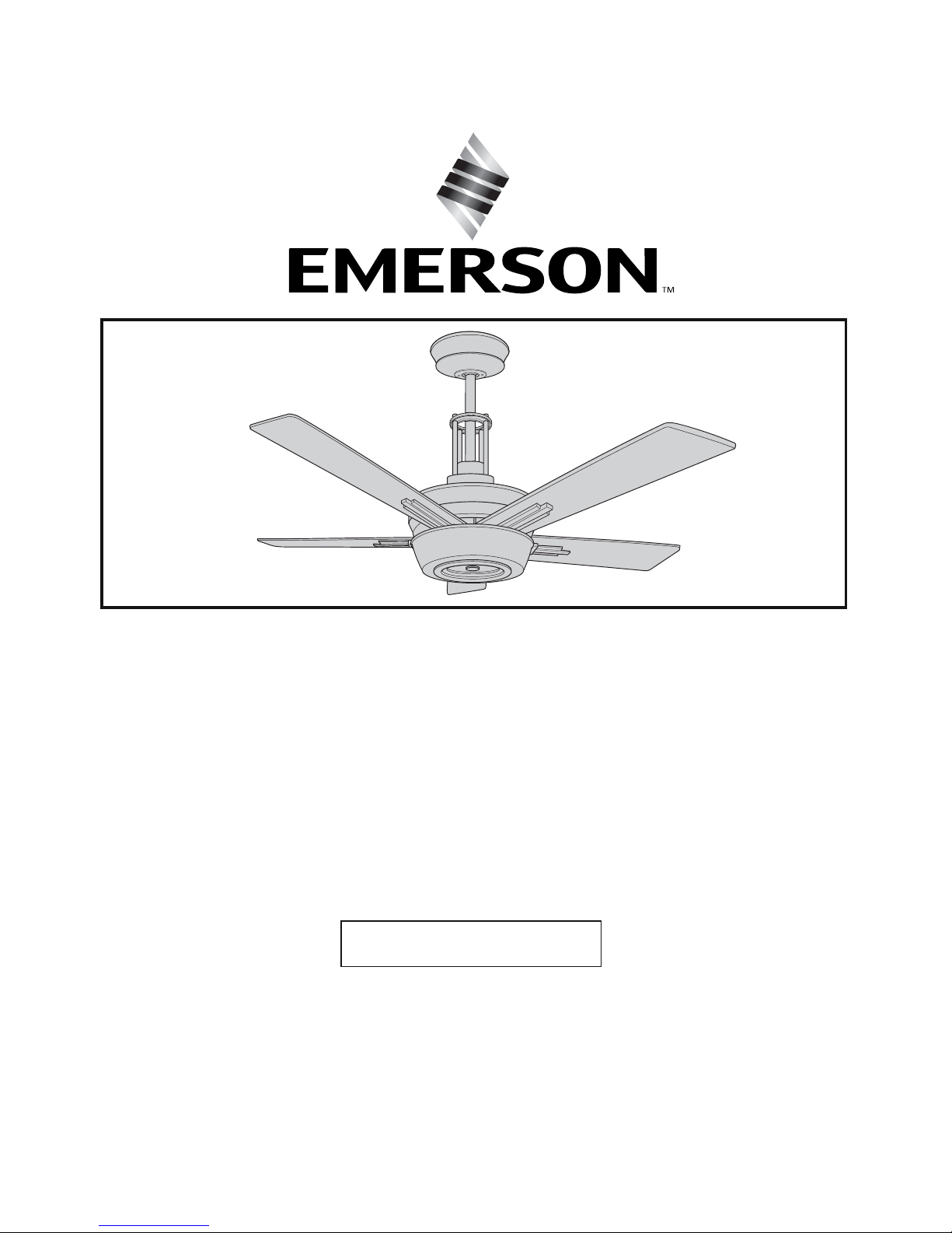
62” Ceiling Fan Owner's Manual
CF995BS00 - Brushed Steel
CF995VNB00 - Vintage Steel
Model Numbers
Net Weight: 34.6 Lbs.
Questions, problems, missing parts: Before returning to the store call
Emerson Electric Customer Service
8 a.m. - 6 p.m., Eastern, Monday-Friday
1-800-654-3545
www.emersonfans.com
2
Safety Instructions
TO REDUCE THE RISK OF FIRE, ELECTRICAL SHOCK,
OR INJURY TO PERSONS, OBSERVE THE
FOLLOWING:
a. Use this unit only in a manner intended by the
manufacturer. If you have questions, contact the
manufacturer.
b. Before servicing or cleaning unit, switch power off
at service panel and lock service panel
disconnecting means to prevent power from being
switched on accidentally. When the service
disconnecting means cannot be locked, securely
fasten a warning device, such as a tag, to the
service panel.
WARNING
!
Additional Safety Instructions for Installation
1. To avoid possible shock, be sure electricity is turned
off at the fuse box before wiring, and do not operate
fan without blades.
2. All wiring must be in accordance with the National
Electrical Code “ANSI/NFPA 70-2014” and Local
Electrical Codes. Use the National Electrical Code if
Local Codes do not exist. The ceiling fan must be
grounded as a precaution against possible electrical
shock. Electrical installation should be made or
approved by a licensed electrician.
3. The outlet box and joist must be securely mounted
and capable of reliably supporting at least 50 pounds.
Use only U.L. outlet boxes listed as “Acceptable for
Fan Support of 22.7 kg. (50 lbs.) or less”, and use the
mounting screws provided with the outlet box.
Most outlet boxes commonly used for support of light
fixtures are not acceptable for fan support and may
need to be replaced. Consult a qualified electrician if
in doubt.
4. The fan must be mounted with the fan blades at least
7 feet from the floor to prevent accidental contact with
the fan blades.
5. Follow the recommended instructions for the proper
method of wiring your ceiling fan. If you do not know
enough about electrical wiring, have your fan installed
by a licensed electrician.
WARNING: To reduce the risk of electrical shock, this
fan must be installed with an isolating wall control/
switch.
NOTE: This fan is suitable for use with solid-state speed
controls.
WARNING: This product is designed to use only those
parts supplied with this product and/or any accessories
designated specifically for use this product by Emerson
Electric Co. Substitution of parts or accessories not
designated for use with this product by Emerson could
result in personal injury or property damage.
WARNING: To reduce the risk of personal injury, do not
bend the blade flange when installing the blade flanges,
balancing the blades or cleaning the fan. Do not insert
foreign objects in between rotating fan blades.
WARNING: To avoid fire, shock or injury, do not use an
Emerson or any other brand of control not specifically
approved for this fan.
NOTE: All setscrews must be checked and re-tightened
where necessary before installation.
NOTE: This fan is suitable for use in wet locations when
installed in a GFCI protected branch circuit.
CAUTION: To Reduce The Risk Of Injury To Persons,
Install Fan So That The Blade Is At Least 2.1 Meters
(7 Feet) Above The Floor.
1. Read your owner’s manual carefully and keep it for
future reference.
2. Be careful with the fan and blades when cleaning,
painting, or working near the fan. Always turn off the
power to the ceiling fan before servicing.
3. Do not put anything into the fan blades while they are
turning.
DATE CODE:
The date code of this fan may be found on the box, stamped in ink on a white label. You should record
this data above and keep it in a safe place for future use.
ETL Model No.: CF995
READ AND SAVE THESE INSTRUCTIONS
Table of Contents
Section Page
Safety Instructions . . . . . . . . . . . . . . . . . . . . . . . . . . . . . . . .2
1. Unpacking Instructions . . . . . . . . . . . . . . . . . . . . . . . . .3-4
2. Electrical Requirements . . . . . . . . . . . . . . . . . . . . . . . . . .4
3. Ceiling Fan Assembly . . . . . . . . . . . . . . . . . . . . . . . . .5-10
4. How to Hang Your Ceiling Fan . . . . . . . . . . . . . . . . . . .11
5. How to Wire Your Ceiling Fan . . . . . . . . . . . . . . . . . . . . .12
6. Installation of Light Bulbs . . . . . . . . . . . . . . . . . . . . . . . .13
7. Transmitter and Receiver Instructions . . . . . . . . . . . . . .14
8. Programming the Receiver Operating Frequency
& High Speed Conditioning of Fan Control . . . . . . . . . .15
Section Page
9. Remote Control Procedures . . . . . . . . . . . . . . . . . . . . . .15
10. Instruction to the User . . . . . . . . . . . . . . . . . . . . . . .16-17
11. Repair Parts . . . . . . . . . . . . . . . . . . . . . . . . . . . . . . .16-17
12. Maintenance . . . . . . . . . . . . . . . . . . . . . . . . . . . . . . . . .17
13. Accessories . . . . . . . . . . . . . . . . . . . . . . . . . . . . . . . . . .18
14. Trouble Shooting . . . . . . . . . . . . . . . . . . . . . . . . . . . . . .18
Ceiling Fan Limited Warranty . . . . . . . . . . . . . . . . . . . . . . .19
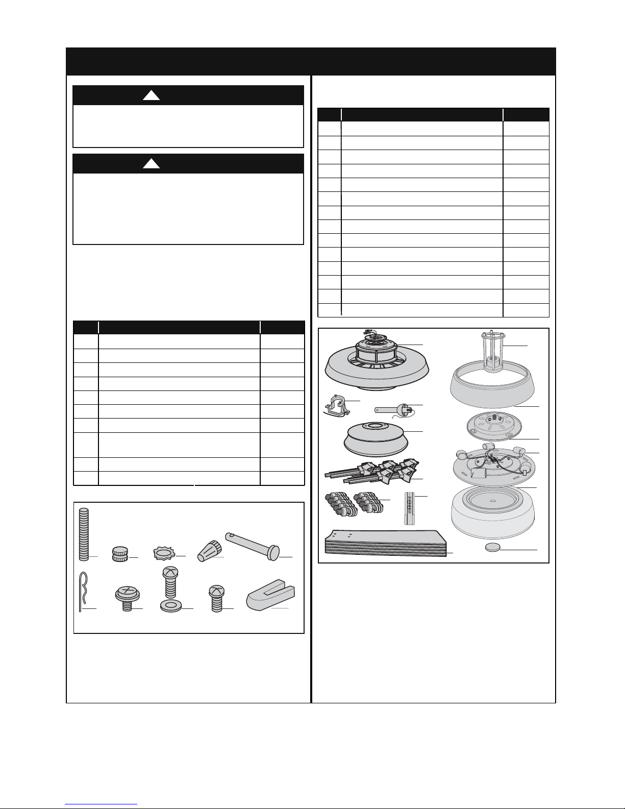
Part Description Quantity
1 Threaded Studs, #8-32 x 1-1/4” 2
2 Knurled Knobs, #8-32 2
3 Lockwashers, External Tooth #8 2
4 Wire Connectors 3
5 Clevis Pin 1
6 Hairpin Clip 1
7 #10-32 x 1/4” Washer Head Blade Screws 21
8 1/4-20 x 3/8” Pan Head Screws
with Lockwashers 11
9 #8-32 x 5/16” Pan Head Blade Screw (Spare) 1
10 Blade Balance Kit 1
1. Unpacking Instructions
3
emersonfans.com
Please contact 1-800-654-3545 for further assistance
ETL Model No.: CF995
This product is designed to use only those parts
supplied with this product and/or any accessories
designated specifically for use with this product by
Emerson Electric Co. Substitution of parts or
accessories not designated for use with this product
by Emerson Electric Co. could result in personal injury
or property damage.
WARNING
!
Do not install or use fan if any part is damaged or
missing. Call Toll-Free for replacement parts:
1-800-654-3545
WARNING
!
1.1
Check to see that you have received the following parts:
NOTE: If you are uncertain of part description, refer
to exploded view illustration below.
NOTE: Place the parts from the loose parts bags in
a small container to keep them from being lost. If
any parts are missing, call 1-800-654-3545 for
replacement parts before proceeding.
1.2
Remove the fan motor assembly from the protective
plastic bag. Place the fan assembly into the lower foam
pad with the bottom of the motor facing up.
The upper foam pad serves as a holder for the fan
during the first stages of assembly.
PACKAGE CONTENTS
Part Description Quantity
A Fan Motor Assembly 1
B Hanger Bracket 1
C Hanger Ball/Downrod Assembly 1
D Ceiling Canopy 1
E Motor Coupler Cover Assembly 1
F Blade Flanges 5
G Fan Blades 5
H Upper Glass Shade 1
I Lower Light Cover 1
J Lower Light Fixture 1
K Lower Glass Shade 1
L Finial Nut 1
M 13W E26 Medium Base CFL 9
N Transmitter w/Storage Bracket 1
HARDWARE BAG CONTENTS
B
M
A
C
D
F
N
E
H
I
J
K
1
6
2
7
3
8
4
9
5
10
G
L
Before assembling your ceiling fan, refer to section on
proper method of wiring your fan (page 12). If you feel
you do not have enough wiring knowledge or
experience, have your fan installed by a licensed
electrician.
WARNING
!
This Manual Is Designed to Make it as Easy as Possible for You to Assemble,
Install, Operate and Maintain Your Ceiling Fan
Tools Needed for Assembly
One Phillips head screwdriver One stepladder
One 1/4” blade screwdriver One wire stripper
Materials
Wiring outlet box and box connectors must be of type
required by the local code. The minimum wire would be
a 3-conductor (2-wire with ground) of following size:
Installed Wire Length
Wire Size A.W.G.
Up to 50 ft. 14
50-100 ft. 12
4
ETL Model No.: CF995
2. Electrical Requirements
Your new ceiling fan will require a grounded electrical
supply line of 120 volts AC, 60 Hz, 15 amp circuit.
To reduce the risk of fire, electric shock, or personal
injury, mount fan to outlet box marked “Acceptable for
Fan Support of 22.7 kg. (50 lbs.) or less”, and use
screws supplied with outlet box. Most outlet boxes
commonly used for support of light fixtures are not
acceptable for fan support and may need to be
replaced. Consult a qualified electrician if in doubt.
WARNING
!
Turning off wall switch is not sufficient. To avoid
possible electrical shock, be sure electricity is turned
off at the main fuse box before wiring. All wiring must
be in accordance with National and Local codes and
the ceiling fan must be properly grounded as a
precaution against possible electrical shock.
WARNING
!
To avoid fire or shock, follow all wiring instructions
carefully.
Any electrical work not described in these
instructions should be done or approved by a licensed
electrician.
WARNING
!
The outlet box must be securely anchored and capable
of withstanding a load of at least 50 pounds.
If your fan is to replace an existing ceiling light fixture,
turn electricity off at the main fuse box at this time and
remove the existing light fixture.
1. Unpacking Instructions (continued)
3. Ceiling Fan Assembly
5
emersonfans.com
Please contact 1-800-654-3545 for further assistance
ETL Model No.: CF995
#10 - 32 x 1/4" WASHER HEAD
Figure 1
Please call Emerson technical support at
1-800-654-3545 if you have any questions about
installation and operation of this ceiling fan.
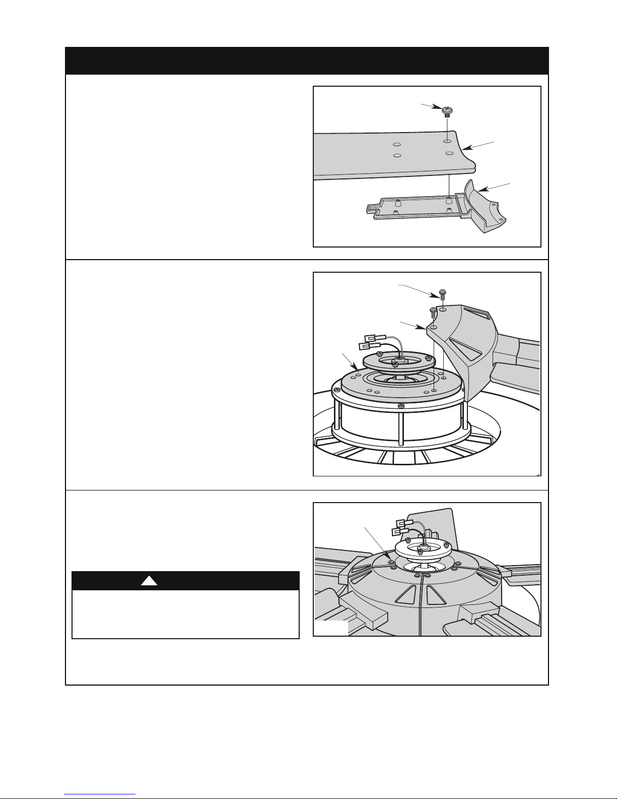
3.1
Mount blade flanges to fan blades using four #10 - 32 x
1/4” washer head blade screws (supplied with fan)
(Figure 1).
Figure 2
Figure 3
3.2
Loosely attach one blade/flange assembly to the motor
hub by securing the two 1/4 - 20 x 3/8” pan head screws
with captive lockwasher. Make sure the screws are
loosely tightened for this step (Figure 2). Repeat this
procedure for other four blade assemblies.
To reduce the risk of personal injury, do not bend the
blade flange when installing the blade flanges,
balancing the blades or cleaning the fan. Do not insert
foreign objects in between rotating fan blades.
WARNING
!
3.3
Once all five blade/flange assemblies are secured to
the motor hub, completely tighten all the 1/4 - 20 x 3/8”
pan head screws with lockwashers at this time
(Figure 3).
SCREWS (4 per blade)
1/4 - 20 x 3/8" PAN HEAD
SCREWS WITH CAPTIVE
LOCKWASHER
(2 per blade/flange assembly)
BLADE/FLANGE ASSEMBLY
MOTOR
HUB
FAN BLADE
BLADE
FLANGE
1/4 - 20 x 3/8" PAN
HEAD SCREW WITH
LOCKWASHER
6
ETL Model No.: CF995
3. Ceiling Fan Assembly (continued)
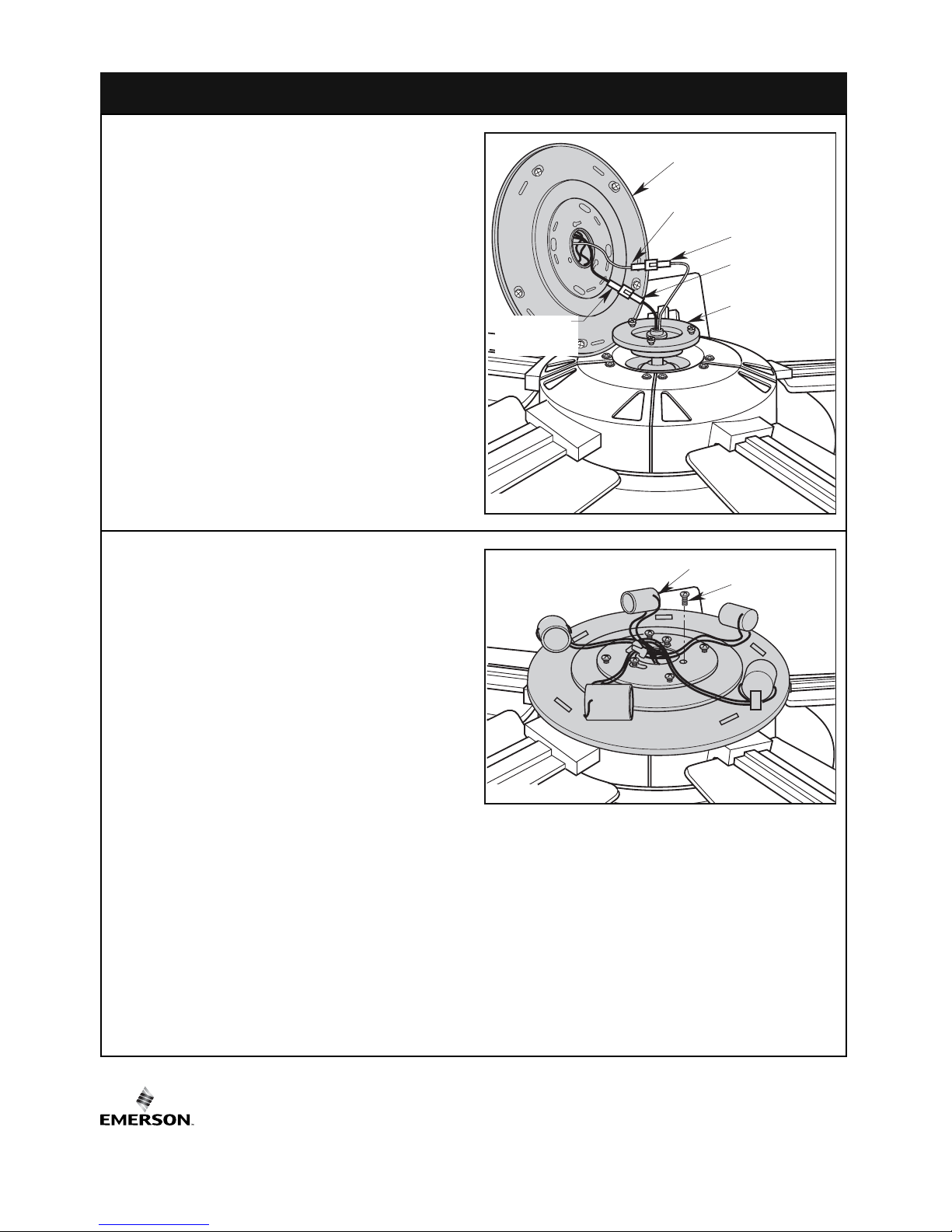
Figure 5
3.5
Remove one #8 - 32 x 5/16” pan head screw from the
lower light adapter (reserve for later use). Loosen the
other two screws to assemble the lower light fixture to
the adapter (Figure 5).
3.6
Position the light fixture above the adapter and carefully
tuck the wires and connectors into the space provided
between the fixture and adapter as the fixture is lowered
onto the adapter. Align the two loosened screw heads
into the key hole slots. Rotate the lower light fixture
clockwise to engage both screws.Tighten both screws
and reinstall the previously removed screw to secure
the fixture (Figure 5).
NOTE: Be careful not to pinch any wires or
connectors between the lower light fixture and the
lower light adapter plate.
Figure 4
3.4
Engage the black connector of the lower light fixture
with the black motor connector. Engage the white
connector of the lower light fixture with the white motor
connector. Make sure each connector latches properly
(Figure 4).
LOWER LIGHT
FIXTURE BLACK
CONNECTOR
LOWER LIGHT FIXTURE
LOWER LIGHT FIXTURE
WHITE CONNECTOR
MOTOR WHITE
CONNECTOR
MOTOR BLACK
CONNECTOR
LOWER LGHT
ADAPTER
LOWER LIGHT FIXTURE
#8 - 32 x 5/16" PAN
HEAD SCREW (3)
 Loading...