

Emerson CF930BS02, CF930ORB02, CF930WW02 Owner's Manual
Part No. F40BP73320002 Form No. BP7332-2
UL Model No.: CF930
READ AND SAVE THESE INSTRUCTIONS
Net Weight: 18.0 Lbs.
ATOMICAL
™
52” Damp Location
Ceiling Fan Owner's Manual
CF930BS02
CF930ORB02
CF930WW02
Model No.
WARNING: To avoid fire, shock, and serious personal injury, follow these
instructions.
Safety Instructions
1. Read your owner’s manual carefully and keep it for future reference.
2. Before servicing or cleaning unit, switch power off at service panel and lock service
panel disconnecting means to prevent power from being switched on accidentally.
When the service disconnecting means cannot be locked, securely fasten a
warning device, such as a tag, to the service panel.
3. Be careful of the fan and blades when cleaning, painting, or working near the fan.
Always turn off the power to the ceiling fan before servicing.
4. Do not put anything into the fan blades while they are turning.
5. Do not operate reversing switch until fan blades have come to a complete stop.
Additional Safety Instructions for Installation
1. To avoid possible shock, be sure electricity is turned off at the fuse box before
wiring, and do not operate fan without blades.
2. The installation is to be in accordance with the National Electrical Code, ANSI/NFPA
70-2008 and Local Codes. Use the National Electrical Code if Local Codes do not
exist. The ceiling fan must be grounded as a precaution against possible electrical
shock. Electrical installation should be made or approved by a licensed electrician.
3. The outlet box and joist must be securely mounted and capable of reliably
supporting at least 50 pounds. Use only U.L. outlet boxes listed as “Acceptable for
Fan Support”, and use the mounting screws provided with the outlet box. Most
outlet boxes commonly used for support of light fixtures are not
acceptable for fan support and may need to be replaced. Consult a qualified
electrician if in doubt.
4. The downrod furnished with the fan provides the minimum recommended floor to
fan blade clearance for an 8 foot ceiling.
5. The fan must be mounted with the fan blades at least 7 feet from the floor to prevent
accidental contact with the fan blades.
6. Follow the recommended instructions for the proper method of wiring your ceiling
fan. If you do not know enough about electrical wiring, have your fan installed by a
licensed electrician.
NOTE: This fan is suitable for use with solid-state speed controls.
WARNING: To reduce the risk of fire or electric shock, this fan should only be used
with fan speed control Model No. UC7067RAL, manufactured by Rhine Electric Co.,
Ltd.
WARNING: This product is designed to use only those parts supplied with this
product and/or any accessories designated specifically for use with this product by
Emerson Electric Co. Substitution of parts or accessories not designated for use with
this product by Emerson Electric Co. could result in personal injury or
property damage.
WARNING: To reduce the risk of personal injury, do not bend the blade flange when
installing the blade flanges, balancing the blades or cleaning the fan. Do not insert
foreign objects in between rotating fan blades.
WARNING: To reduce the risk of electric shock, this fan must be installed with an
isolating wall control/switch.
!
WARNING
DATE CODE:
The date code of this fan may be found on the box, stamped in ink on a white label.
You should record this data above and keep it in a safe place for future use.
2
UL Model No.: CF930
3
THIS FAN IS SUITABLE FOR DAMP LOCATIONS
SUCH AS COVERED PORCHES, COVERED PATIOS, AND COVERED
DECKS...ANYWHERE THERE IS A ROOF OVERHEAD.
This Manual is Designed to Make it as Easy as Possible for You to
Assemble, Install, Operate and Maintain Your Ceiling Fan
Do not install or use fan if any part is
damaged or missing. Call Toll-Free:
1-800-654-3545
!
WARNING
This product is designed to use only
those parts supplied with this product
and/or any accessories designated
specifically for use with this product by
Emerson Electric Co. Substitution of
parts or accessories not designated for
use with this product by Emerson Electric
Co. could result in personal injury or
property damage.
!
WARNING
Tools Needed for Assembly
One Phillips head screwdriver
One wire stripper
One stepladder
Materials
Wiring, outlet box and box connectors
must be of type required by the local code.
The minimum wire would be a 3-conductor
(2-wire with ground) of the following sizes:
Installed Wire Length Wire Size A.W.G.
Up to 50 ft. 14
50-100 ft. 12
Before assembling your ceiling fan, refer
to section on proper method of wiring
your fan (Page 9). If you feel you do not
have enough wiring knowledge or
experience, have your fan installed by a
licensed electrician.
!
WARNING
Unpacking Instructions
For your convenience, check-off boxes are provided next to each step. As each
step is completed, place a check mark in the box. This will insure that all steps
have been completed and will be helpful in finding your place should you be
interrupted.
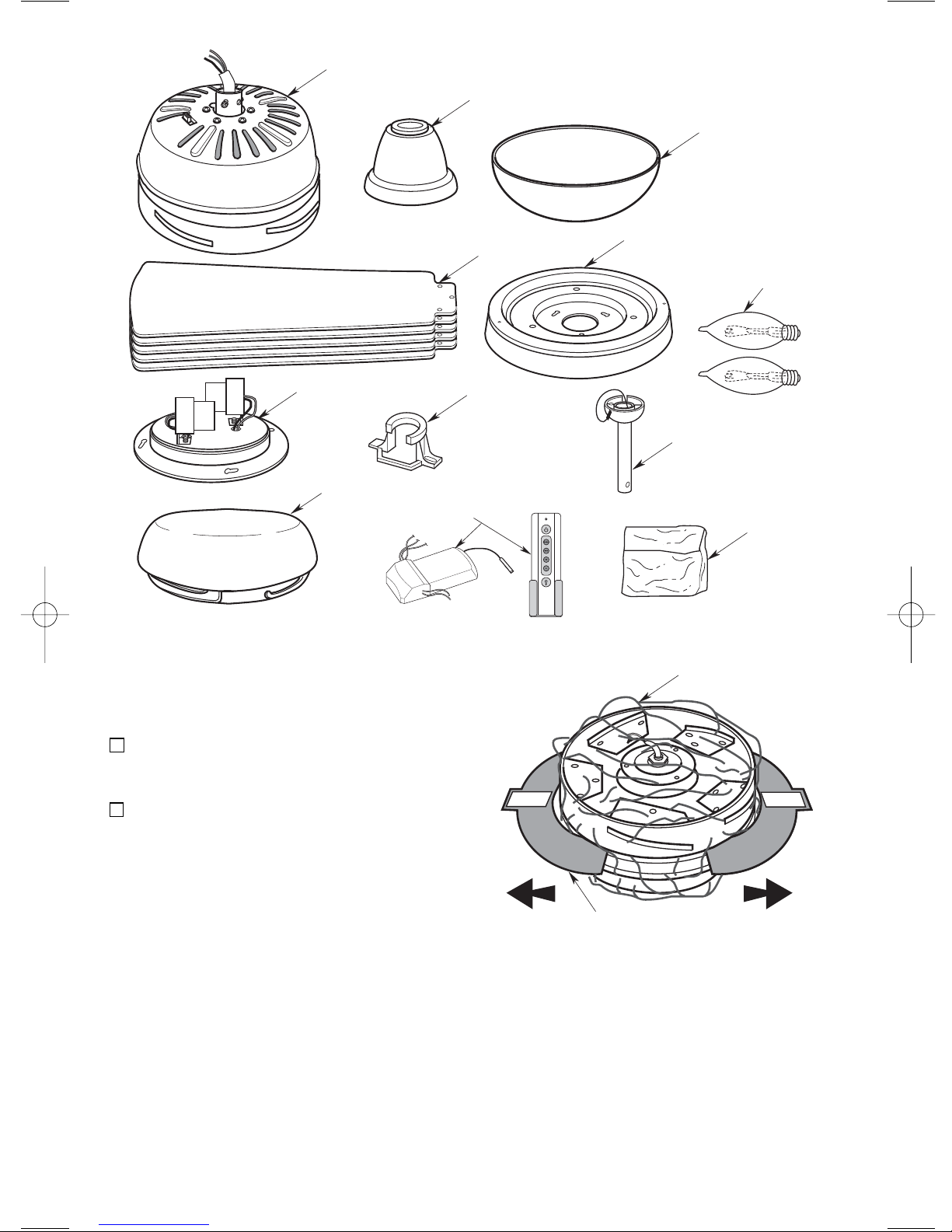
NOTE: If you are uncertain of part
description, refer to exploded view
illustration.
a. Fan motor assembly
b. One coupling cover
c. One ceiling cover
d. Five fan blades
e. One lower housing
f. One light kit assembly
g. One hanger bracket
h. One hanger ball/4.5” downrod assembly
i. One lower glass
j. One fan/light remote control
(transmitter and receiver)
k. Two 60-watt (maximum) candelabra
base bulbs
l. One loose parts bag containing:
1. One clevis pin
2. One hairpin clip
3. Three 12 ga. wire connectors
4. Six 18 ga. wire connectors
5. Two #8-32 x 1-1/4” threaded studs
6. Two #8 external tooth lockwashers
7. Two #8-32 knurled knobs
8. Sixteen M5 x 12mm washer head
screws
9. Seven M4 x 10mm serrated head
screws
10. One balancing kit
1. Open carton containing fan. Remove
top half of styrofoam unit. Remove
parts and check to see that you have
received the following parts:
UL Model No.: CF930
4
2. Remove and discard the two cardboard
shipping retainers securing the motor
hub in the motor housing assembly.
3. Remove the fan motor assembly from
the protective plastic bag. Place all
carton contents on a protective surface.
A. FAN MOTOR ASSEMBLY
NOTE: Place the parts from the loose
parts bags in a small container to keep
them from being lost.
UL Model No.: CF930
B. COUPLING COVER
C. CEILING COVER
F. LIGHT KIT ASSEMBLY
I. LOWER GLASS
J. FAN/LIGHT
REMOTE CONTROL
D. FAN BLADES
G. HANGER BRACKET
E. LOWER
HOUSING
K. 60-WATT
CANDELABRA
BULBS
H. HANGER BALL/
4.5" DOWNROD
ASSEMBLY
L. LOOSE
PARTS BAG
PROTECTIVE
PLASTIC BAG
IMPORTANT
IMPORTANT
CARDBOARD
SHIPPING RETAINER (2)
5
Your new ceiling fan will require a
grounded electrical supply line of 120 volts
AC, 60 Hz, 15 amp circuit.
The outlet box must be securely anchored
and capable of withstanding a load of at
least 50 pounds.
General
Your Emerson ceiling fan comes supplied
with a Fan/Light Remote Control which
consists of a remote control (transmitter)
and a remote control receiver mounted
under the ceiling cover. This system
allows you to regulate your ceiling fan
speed and light intensity.
NOTE: An optional Emerson Electric
SW406 Wall Control may also be used
to control your ceiling fan.
To reduce the risk of fire, electric shock,
or personal injury, mount fan to outlet box
marked “Acceptable for Fan Support”,
and use screws supplied with outlet box.
Most outlet boxes commonly used for
support of light fixtures are not
acceptable for fan support and may need
to be replaced. Consult a qualified
electrician if in doubt.
!
WARNING
If your fan is to replace an existing ceiling
light fixture, turn electricity off at the main
fuse or circuit breaker box at this time and
remove the existing light fixture.
IMPORTANT: Your ceiling fan will not
function properly, and may be
damaged, if used with any wall dimmer
switch or control other than the
Emerson Electric Fan/Light Wall
Control supplied with the fan, or an
optional Emerson Electric SR100
Remote Control.
Electrical Requirements Ceiling Fan Procedures
How to Assemble Your
Ceiling Fan
Turning off wall switch is not sufficient.
To avoid possible electrical shock, be
sure electricity is turned off at the main
fuse or circuit breaker box before wiring.
All wiring must be in accordance with
National and Local codes and the ceiling
fan must be properly grounded as a
precaution against possible electrical
shock.
!
WARNING
UL Model No.: CF930
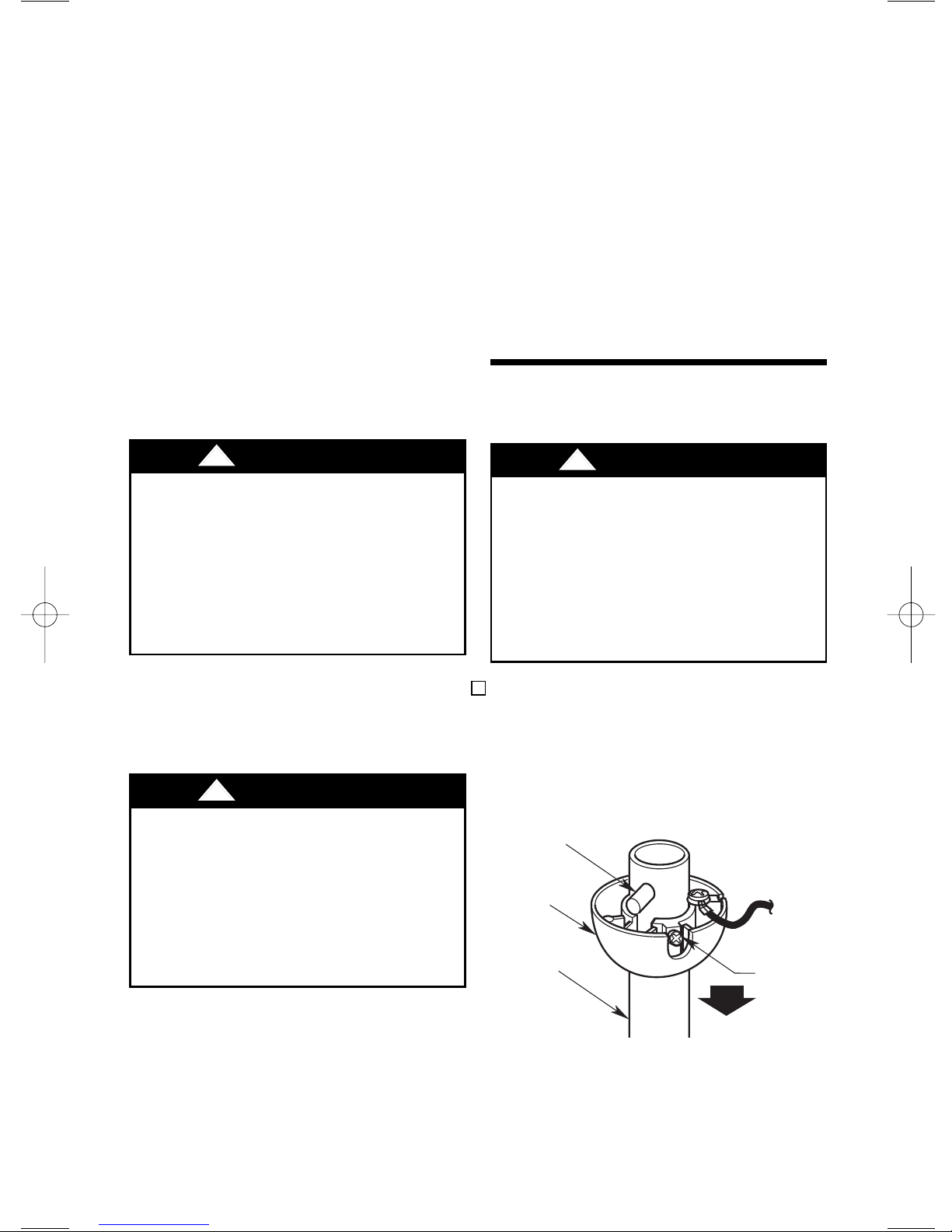
1. Remove the hanger ball by loosening
the setscrew in the hanger ball until the
ball falls freely down the downrod
(Figure 1). Remove the clevis pin from
the downrod, then remove the hanger
ball. Retain the pin and hanger ball for
reinstallation in Step 5.
Figure 1
PIN
HANGER
BALL
DOWNROD
SETSCREW
6
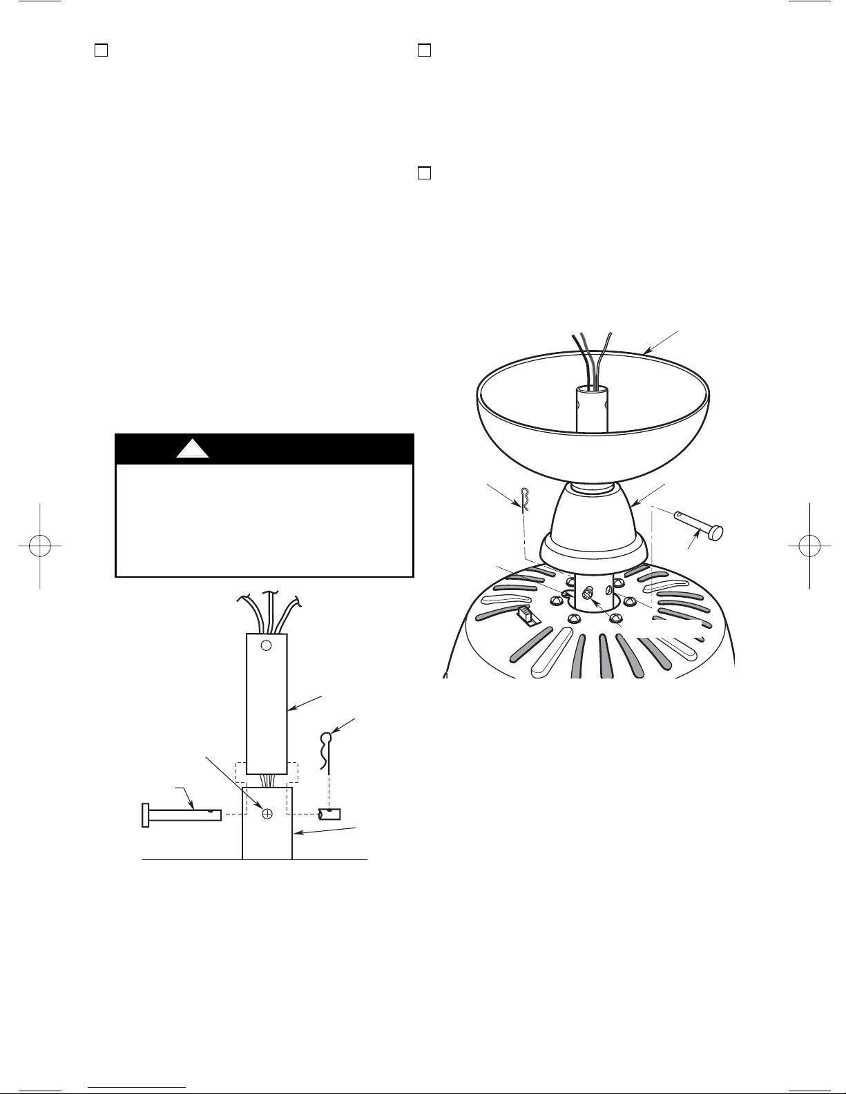
2. Loosen setscrew in motor coupling if
necessary. Separate, untwist and
unkink the three 80” motor leads. Route
the motor lead wires through the
downrod. Align the clevis pin holes in
the downrod with the holes in the motor
coupling. Install the clevis pin and
secure with the hairpin clip (Figure 2).
The clevis pin must go through the
holes in the motor coupling and the
holes in the downrod. Be sure to push
the straight leg of the hairpin clip
through the hole near the end of the
clevis pin until the curved portion of the
hairpin clip snaps around the clevis pin.
The hairpin clip must be properly
installed to prevent the clevis pin from
working loose. Pull on the downrod to
make sure the clevis pin is properly
installed.
Figure 2
Figure 3
It is critical that the clevis pin in the motor
coupling is properly installed and the
setscrew securely tightened. Failure to
verify that the pin and setscrew are
properly installed (as shown in Figure 2)
could result in the fan falling.
!
WARNING
3. While pulling up on the downrod,
securely tighten the two setscrews in
the motor coupling (Figure 3).
NOTE: The setscrews must be properly
installed as described above, or fan
wobble could result.
4. Make sure the grommet is properly
installed in the coupling cover then
slide the coupler cover on the downrod
until it rests on the motor housing.
Place the ceiling cover over the
downrod. Be sure both the ceiling cover
and the coupler cover are oriented
correctly (Figure 3).
UL Model No.: CF930
CEILING
CANOPY
SETSCREW (2)
SETSCREW
CLEVIS PIN
CLEVIS PIN
DOWNROD
DOWNROD
HAIRPIN
HAIRPIN CLIP
CLIP
MOTOR
COUPLING
MOTOR
COUPLING
HAIRPIN
CLIP
MOTOR
COUPLING
COUPLER
COVER
CLEVIS PIN
SETSCREW (2)
 Loading...