

Emerson CF805SWW01, CF805SAB01, CF805SAW01, CF804SBS01, CF804SORB01 Owner's Manual
...
Part No. F40BP71920008 Form No. BP7192-8
Revision: 131101 U.L. Model No.: 52-CL
READ AND SAVE THESE INSTRUCTIONS
Ceiling Fan Owner's Manual
52” Model Numbers
42” Model Numbers
CF805SAB01 - Antique Brass
CF805SAW01 - Summer White
CF805SBS01 - Brushed Steel
CF805SORB01 - Oil Rubbed
Bronze
CF805SWW01 - Appliance
White
Net Weight: 13.9 Lbs.
CF804SBS01 - Brushed Steel
CF804SORB01 - Oil Rubbed
Bronze
CF804SWW01 - Appliance
White
Net Weight: 11.2 Lbs.
1-800-654-3545
www.emersonfans.com
Questions, problems, missing parts: Before returning to the store call
Emerson Electric Customer Service 8 a.m. - 6 p.m., Eastern, Monday-Friday
CONTEMPORARY SNUGGER
™
Safety Instructions
TO REDUCE THE RISK OF FIRE, ELECTRICAL SHOCK,
OR INJURY TO PERSONS, OBSERVE THE
FOLLOWING:
a. Use this unit only in a manner intended by the
manufacturer. If you have questions, contact the
manufacturer.
b. Before servicing or cleaning unit, switch power off
at service panel and lock service panel
disconnecting means to prevent power from being
switched on accidentally. When the service
disconnecting means cannot be locked, securely
fasten a warning device, such as a tag, to the
service panel.
WARNING
!
Additional Safety Instructions for Installation
1. To avoid possible shock, be sure electricity is turned
off at the fuse box before wiring, and do not operate
fan without blades.
2. All wiring must be in accordance with the National
Electrical Code “ANSI/NFPA 70-2014” and Local
Electrical Codes. Use the National Electrical Code if
Local Codes do not exist. The ceiling fan must be
grounded as a precaution against possible electrical
shock. Electrical installation should be made or
approved by a licensed electrician.
3. The outlet box and joist must be securely mounted
and capable of reliably supporting at least 50 pounds.
Use only U.L. outlet boxes listed as “Acceptable for
Fan Support of 22.7kg. (50 lbs.) or less”, and use the
mounting screws provided with the outlet box. Most
outlet boxes commonly used for support of light
fixtures are not acceptable for fan support and may
need to be replaced. Consult a qualified electrician if
in doubt.
4. The downrod furnished with the fan provides the
minimum recommended floor to fan blade clearance
for an 8 foot ceiling.
5. The fan must be mounted with the fan blades at least
7 feet from the floor to prevent accidental contact with
the fan blades.
6. Follow the recommended instructions for the proper
method of wiring your ceiling fan. If you do not know
enough about electrical wiring, have your fan installed
by a licensed electrician.
WARNING: To reduce the risk of electrical shock, this
fan must be installed with an isolating wall
control/switch.
NOTE: This fan is suitable for use with solid-state speed
controls.
WARNING: This product is designed to use only those
parts supplied with this product and/or any accessories
designated specifically for use this product by Emerson
Electric Co. Substitution of parts or accessories not
designated for use with this product by Emerson could
result in personal injury or property damage.
WARNING: To reduce the risk of personal injury, do not
bend the blade flange when installing the blade flanges,
balancing the blades or cleaning the fan. Do not insert
foreign objects in between rotating fan blades.
NOTE: All setscrews must be checked and re-tightened
where necessary before installation.
1. Read your owner’s manual carefully and keep it for
future reference.
2. Be careful of the fan and blades when cleaning,
painting, or working near the fan. Always turn off the
power to the ceiling fan before servicing.
3. Do not put anything into the fan blades while they are
turning.
4. Do not operate reversing switch until fan blades have
come to a complete stop.
DATE CODE:
The date code of this fan may be found on the box, stamped in ink on a white label. You should record
this data above and keep it in a safe place for future use.
READ AND SAVE THESE INSTRUCTIONS
2
U.L. Model No.: 52-CL
This Manual Is Designed to Make it as Easy as Possible for You to
Assemble, Install, Operate and Maintain Your Ceiling Fan
Tools Needed for Assembly
One Phillips head screwdriver
One 1/4" blade screwdriver
One stepladder
One wire stripper
Three wire connectors (supplied)
Materials
Wiring electrical box and box connectors must be of
type required by local code. The minimum wire would
be a 3-conductor (2-wire with ground) of size shown at
right.
Installed Wire Length Wire Size A.W.G.
Up to 50 ft. 14
50 - 100 ft. 12
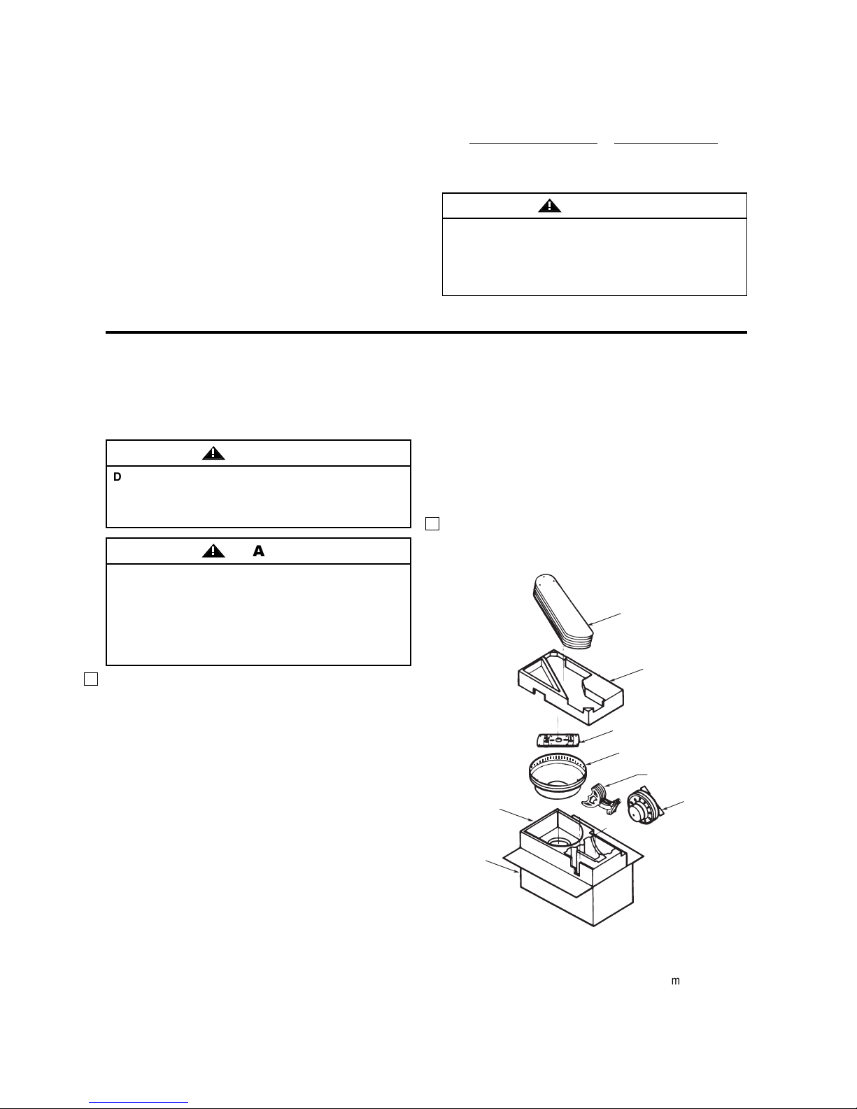
1.Check to see that you have received the following
parts:
NOTE: If you are uncertain of part description,
refer to exploded view illustration.
a. Fan housing
b. Mounting plate
c. Fan motor assembly
d. Five fan blades
e. Five blade flanges with captive screws
f. One loose parts bag containing:
1. Sixteen M5 x 6mm Phillips washer
head screws
2. CF804S Only: M5 x 13mm Phillips pan head
screw with lockwasher
CF805S Only: M6 x 14mm Phillips pan head
screw with lockwasher
3. Five M5 x 10mm Phillips pan head screws
with internal tooth washers
4. Four 1/4” hex locknuts
5. One wood pendant
6. One chain coupling
7. Three wire connectors
NOTE: Place the parts from the loose parts bag in
a small container to keep them from being lost. If
any parts are missing, contact your local retailer
or catalog outlet for replacement before
proceeding.
2. Remove the fan assembly from the protective
plastic bag. Place the fan assembly into the upper
foam pad with the lead wires up.
Unpacking Instructions
For your convenience, check-off boxes are provide next to each step. As each step is completed, place a
check mark in the box. This will insure that all steps have been completed and will be helpful in finding
your place should you be interrupted.
Before assembling your ceiling fan, refer to section on
proper method of wiring your fan (page 5). If you feel
you do not have enough wiring knowledge or
experience, have your fan installed by a licensed
electrician.
WARNING
!
Do not install or use fan if any part is damaged or
missing. Call Toll-Free:
1-800-654-3545
This product is designed to use only those parts
supplied with this product and/or any accessories
designated specifically for use with this product by
Emerson Company. Substitution of parts or
accessories not designated for use with this product
by Emerson Company could result in personal injury
or property damage.
WARNING
!
WARNING
!
3
emersonfans.com
Please contact 1-800-654-3545 for further assistance
U.L. Model No.: 52-CL
LOWER
FOAM PAD
CARTON
FAN
BLADES
UPPER
FOAM PAD
MOUNTING
PLATE
FAN
HOUSING
BLADE FLANGES WITH
CAPTIVE SCREWS
FAN
MOTOR
ASSEMBLY
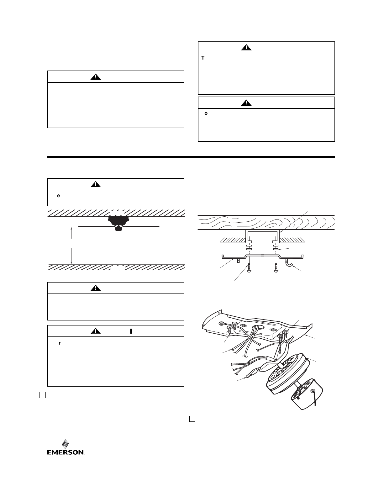
1. Securely attach the mounting plate to the outlet box
(Figure 2) using two screws (supplied with outlet
box). Pull the black, white and ground wires out of
the outlet box through the hole in the mounting
plate and lay them to the side as shown in Figure 3.
NOTE: For better fan performance make sure the
mounting plate is level. Additional washers (not
included) may be needed to insert between the
electrical box and mounting plate (Figure 2).
2. Carefully lift the fan motor assembly and engage
the slot in the motor bracket with the hook on the
mounting plate so that it is securely suspended
(Figure 3). Then connect wiring to your fan
according to section "HOW TO WIRE YOUR
CEILING FAN".
Electrical Requirements
Your new ceiling fan will require a grounded electrical
supply line of 120 volts AC, 60 Hz, 15 amp circuit.
The outlet box must be securely anchored and
capable of withstanding a load of at least 50 pounds.
If your fan is to replace an existing ceiling light fixture,
turn electricity off at the main fuse box at this time and
remove the existing light fixture.
How to Hang Your Ceiling Fan
Figure 1
Figure 2
Figure 3
To reduce the risk of fire, electric shock, or personal
injury, mount fan to outlet box marked “Acceptable
for Fan Support of 22.7kg. (50 lbs.) or less”, and use
screws supplied with outlet box. Most outlet boxes
commonly used for support of light fixtures are not
acceptable for fan support and may need to be
replaced. Consult a qualified electrician if in doubt.
WARNING
!
Turning off wall switch is not sufficient. To avoid
possible electrical shock, be sure electricity is
turned off at the main fuse box before wiring. All
wiring must be in accordance with National and
Local Codes and the ceiling fan must be properly
grounded as a precaution against possible
electrical shock.
WARNING
!
To avoid fire or shock, follow all wiring instructions
carefully.
Any electrical work not described in these
instructions should be done or approved by a
licensed electrician.
WARNING
!
The fan must be hung with at least 7' of clearance
from floor to blades (Figure 1).
WARNING
!
To reduce the risk of fire, electric shock, or personal
injury, mount fan to outlet box marked “Acceptable
for Fan Support of 22.7kg. (50 lbs.) or less”, and use
screws supplied with outlet box. Most outlet boxes
commonly used for support of light fixtures are not
acceptable for fan support and may need to be
replaced. Consult a qualified electrician if in doubt.
The outlet box and joist must be securely mounted
and capable of supporting at least 50 lbs. Use only a
U.L. outlet box listed as “Acceptable for Fan Support
of 22.7kg. (50 lbs.) or less”.
WARNING
!
WARNING
!
4
U.L. Model No.: 52-CL
AT LEAST
7'
CEILING
OUTLET BOX
LEVELING WASHERS
(IF REQUIRED)
FLOOR
MOUNTING
PLATE
MOUNTING SCREW
(SUPPLIED WITH
OUTLET BOX)
THREADED
STUDS
SUPPLY
WIRE LEADS
MOTOR
BRACKET
HOOK
RUBBER WASHER
MOUNTING
PLATE
FAN
MOTOR
ASSEMBLY
 Loading...