

Emerson CF788ORB00, CF788AP00, CF788CK00, CF788GBZ00 Owner's Manual
Part No. F40BP74270002 Form No. BP7427-2
ETL Model No.: CF788
READ AND SAVE THESE INSTRUCTIONS
Damp Location
Ceiling Fan Owner's Manual
CF788AP00 - Antique Pewter
CF788CK00 - Chalk
CF788GBZ00 - Gilded Bronze
CF788ORB00 - Oil Rubbed Bronze
Model Numbers
CARRERA GRANDE ECO
™
54”, 60” or 72” Fan Blades
Not Included
Net Weight: 17.2 Lbs.
WARNING: To avoid fire, shock, and serious personal injury, follow these instructions.
Safety Instructions
1. Read your owner’s manual carefully and keep it for future reference.
2. Before servicing or cleaning unit, switch power off at service panel and lock service panel
disconnecting means to prevent power from being switched on accidentally. When the service
disconnecting means cannot be locked, securely fasten a warning device, such as a tag, to the
service panel.
3. Be careful of the fan and blades when cleaning, painting, or working near the fan. Always turn off
the power to the ceiling fan before servicing.
4. Do not put anything into the fan blades while they are turning.
5. Do not operate reversing switch until fan blades have come to a complete stop.
Additional Safety Instructions for Installation
1. To avoid possible shock, be sure electricity is turned off at the fuse box before wiring, and do not
operate fan without blades.
2. All wiring must be in accordance with the National Electrical Codes “ANSI/NFPA 70-2008” and
Local Electrical Codes. Use the National Electrical Code if Local Codes do not exist. The ceiling
fan must be grounded as a precaution against possible electrical shock. Electrical installation
should be made or approved by a licensed electrician.
3. The outlet box and joist must be securely mounted and capable of reliably supporting at least
50 pounds. Use only U.L. outlet boxes listed as “Acceptable for Fan Support of 22.7 kg. (50 lbs.)
or less”, and use the mounting screws provided with the outlet box. Most outlet boxes commonly
used for support of light fixtures are not acceptable for fan support and may need to be replaced.
Consult a qualified electrician if in doubt.
4. The downrod furnished with the fan provides the minimum recommended floor to fan blade
clearance for an 8 foot ceiling.
5. The fan must be mounted with the fan blades at least 7 feet from the floor to prevent accidental
contact with the fan blades.
6. Follow the recommended instructions for the proper method of wiring your ceiling fan. If you do
not know enough about electrical wiring, have your fan installed by a licensed electrician.
NOTE: This fan is suitable for use with solid-state speed controls.
WARNING: To reduce the risk of fire or electric shock, this fan should only be used with fan speed
control, Model No. FR-7861LMB manufactured by Rhine Electric Co., Ltd.
WARNING: To avoid fire, shock or injury, do not use an Emerson or any other brand of control not
specifically approved for this fan.
WARNING: This product is designed to use only those parts supplied with this product and/or any
accessories designated specifically for use with this product by Emerson Electric Co. Substitution
of parts or accessories not designated for use with this product by Emerson Electric Co. could
result in personal injury or property damage.
WARNING: To reduce the risk of personal injury, do not bend the blade flange when installing the
blade flanges, balancing the blades or cleaning the fan. Do not insert foreign objects in between
rotating fan blades.
WARNING: To reduce the risk of electrical shock, this fan must be installed with an isolating wall
control/switch.
WARNING
2
!
DATE CODE:
The date code of this fan may be found on the box, stamped in ink on a white label.
You should record this data above and keep it in a safe place for future use.
ETL Model No.: CF788
3
ETL Model No.: CF788
EMERSON QUICK START GUIDE
The Quick Start Guide covers the installation
instructions common for ceiling fan operations. If
additional assistance with wiring, alternate hanging
systems, or lighting options, proceed to the complete
instructions of this Owner’s Manual.
The Quick Start Guide sections include page numbers
to correspond with the appropriate sections of the
Owner’s Manual for detailed instructions.
* See Unpacking Instructions for a complete list of
parts for installation.
How to Put Your Ceiling Fan Together (page 6)
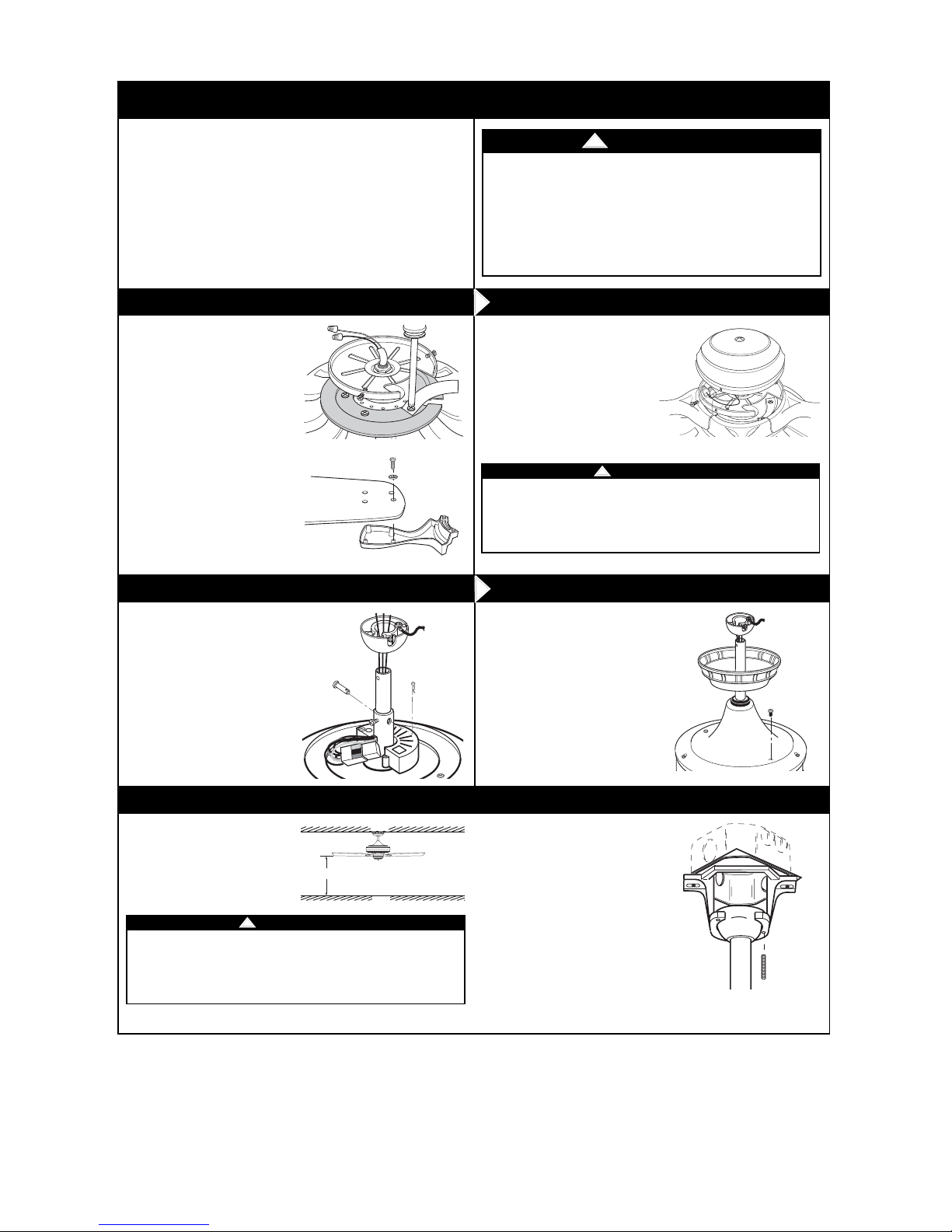
1. Unscrew and discard each
shipping retainer screw and
retainer.
1. Disconnect electrical power to
the branch circuit at the
circuit breaker or fuse box
before attempting to install
the ceiling fan hanger bracket
on the outlet box.
2. The fan must be hung with at
least 7’ of clearance from
floor to blades.
3. Attach the hanger bracket to
the outlet box.
4. Seat the hanger ball/downrod
assembly on the hanger
bracket.
Hanging Your Ceiling Fan (page 10)
To reduce the risk of fire, electric shock, or personal
injury, mount fan to outlet box marked “Acceptable for Fan
Support of 22.7 kg. (50 lbs.) or less”, and use screws
supplied with outlet box. Most outlet boxes commonly used
for support of light fixtures are not acceptable for fan
support and may need to be replaced. Consult a qualified
electrician if in doubt.
!
WARNING
2. Attach the blade flanges to
the fan blades.
3. Attach the blade/flange
assembly to the motor hub.
Installation of Downrod (page 8)
1. Remove the hanger ball from
the downrod.
2. Install the downrod to the
motor coupling using the
clevis pin and hairpin clip.
3. Tighten the setscrews.
Installation of Ceiling Fan (pages 8 and 9)
1. Install the coupler cover and
ceiling cover onto the
downrod.
2. Reinstall the hanger ball onto
the downrod, place the pin
into the hanger ball and
tighten the setscrew.
Installation of Switch Housing (page 7)
1. Tuck blue and white wires
carefeully under the switch
housing cover and attach
witht he three switch housing
mounting screws.
Turning off wall switch is not sufficient. To avoid possible electrical
shock, be sure electricity is turned off at the main fuse or circuit
breaker box before wiring. All wiring must be in accordance with
National and Local codes and the ceiling fan must be properly
grounded as a precaution against possible electrical shock.
!
WARNING
O
N
D
r
e
b
b
u
R
e
la
v
l
p
a
t
o
s
S
n
o
I
s
e
o
r
m
L
o
o
L
f
r
r
e
a
r
i
a
e
T
t
R
i
B
Y
u
!
e
d
Q
E
r
J
!
a
T
a
l
c
A
a
s
T
i
b
O
m
N
E
r
o
CEILING
AT LEAST
7'
FLOOR
4
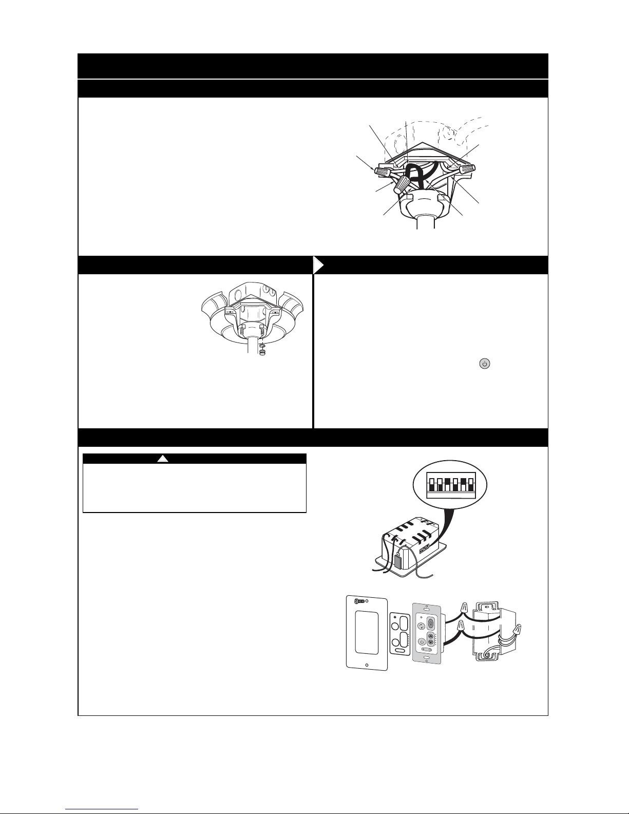
1. Connect the green grounding lead from the hanger ball and the
green grounding lead from the hanger bracket to the grounding
conductor of supply (this may be a bare wire or wire with green
colored insulation). Securely connect wires with wire
connectors supplied.
NOTE: If you are using an Emerson Light Fixture with your fan,
see Light Fixture Owner’s Manual for wiring.
2. Securely connect the fan motor white wire to the supply white
(neutral) wire using wire connector supplied. Securely connect
the fan motor black wire to the supply black (hot) wire using
wire connector supplied. After connections have been made,
turn leads upward and carefully push leads into
the outlet box, with the white and green leads on one side of the
outlet box and the black leads on the other side of
the outlet box.
Wiring Ceiling Fan (page 11)
1. Remove faceplate and screws from existing wall control. Pull
control out from the wall box. Determine the “hot” wire and the
“load” wire and disconnect these wires from control. Do not
attempt to disconnect any wires not already connected to
existing control.
2. Before installing wall control, place wall control in “OFF” mode
by pushing “ON/OFF” switch to the “OFF” position.
3. Connect one black wire of wall control to the “hot” wire.
Securely connect wires with wire connectors supplied.
4. Connect one black wire of wall switch to the “load” (black) wire
in wall box. Securely connect wires with wire connector
supplied.
5. Screw wall control into wall box using the supplied screws.
Leave wall control in “OFF” mode until fan installation is
completed.
6. The wall control is supplied with a white, ivory, and almond
color switch covers. Choose the finish that best suits your
needs and snap the cover onto the wall control.
7. Install decorator wall plate using the two screws provided with
wall plate. Leave wall control in “OFF” mode until fan installation
is completed.
Installation of Wall Control (pages 12, 13 & 14)
1. Separate the grounded white
neutral and green wires on
one side of the outlet box
from the ungrounded black
and blue wires on the other
side of the outlet box
2. Insert the grounded green
and white wires into one side
of the outlet box, and the
ungrounded black and blue
wires into the other side of
the outlet box.
3. Screw the two threaded studs
into the tapped holes in the
hanger bracket.
Installation of Ceiling Cover (page 11)
Your wall control has code switches which must be set in one of
32 possible code combinations. The five levers (numbered 1, 2, 3,
4, and 5) on the switches are factory-set in the ON (up) position.
Change the switch settings as follows:
1. Slide the five switch levers in the wall control to your choice of
ON (up) or down positions. Use a ball-point pen or small
screwdriver and slide the levers firmly up or down.
2. When power is restored after installation of the wall control,
push and hold the fan OFF button ( ) for 3 to 5
seconds to set the code in the receiver.
3. The sixth switch marked ON and I is for dimming control of
lights: Set switch to ON to allow for dimming of the lights. Set
switch to I for no dimming of the lights such as for fluorescent
bulbs.
Programming Receiver (page 12)
EMERSON QUICK START GUIDE
4. Install the ceiling cover onto
the hanger bracket. using the
studs, lock washers and
knurled nuts supplied.
Turning off wall switch is not sufficient. To avoid possible electrical
shock, be sure electricity is turned off at the main fuse or circuit
breaker box before wiring. All wiring must be in accordance with
National and Local codes and the ceiling fan must be properly
grounded as a precaution against possible electrical shock.
!
WARNING
ETL Model No.: CF788
* For additional installation review full instructions on pages
13 and 14.
GROUND
WIRE
LISTED
WIRE
CONNECTOR (3)
GREEN WIRE
(GROUND) FROM
HANGER BRACKET
GREEN WIRE
(GROUND) FROM
HANGER BALL
BLACK
FAN WIRE
WHITE SUPPLY
(NEUTRAL)
WHITE FAN
WIRE
BLACK SUPPLY
(HOT)
NOTE: CEILING COVER OMITTED FOR CLARITY.
ON
1
23
4
5I
BLK
HOT
T
O
1
2
0
E
V
A
C
C
S
R
O
U
T
O
L
O
D
A
D
N
BLACK
U
O
R
G
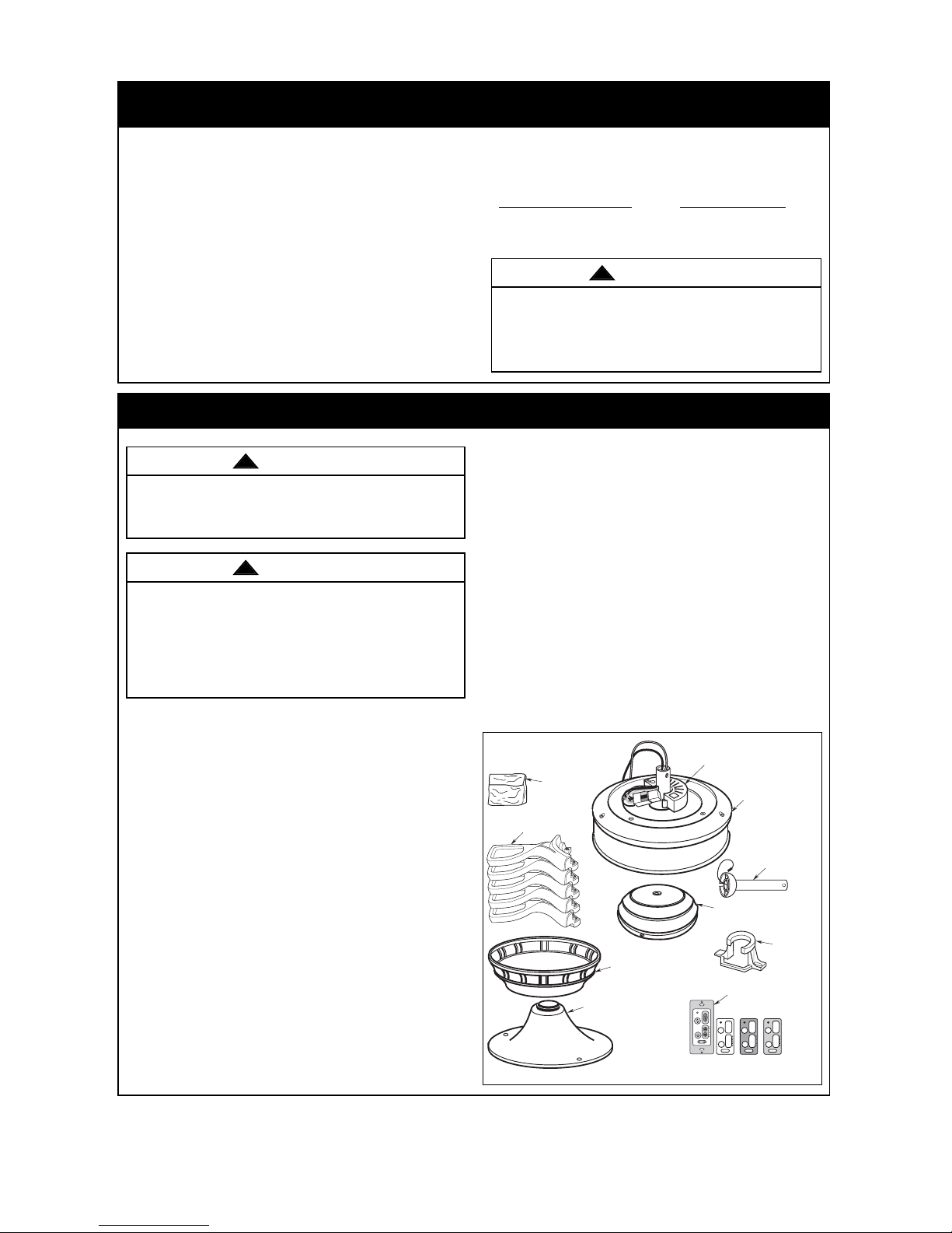
Unpacking Instructions
THESE FAN MODELS ARE SUITABLE FOR DAMP LOCATIONS SUCH AS COVERED PORCHES,
COVERED PATIOS, AND COVERED DECKS... ANYWHERE THERE IS A ROOF OVERHEAD.
1. Check to see that you have received the following
parts:
NOTE: If you are uncertain of part description,
refer to exploded view illustration.
a. Fan motor assembly
b. One switch housing
c. One ceiling cover
d. Five blade flanges
e. One hanger ball/4.5” downrod assembly
f. One hanger bracket
g. One motor coupling cover
h. One transmitter control with
switch covers
i. One receiver control
j. One loose parts bag containing:
1. Twenty-one #10-24 x 12mm washer head
blade screws
2. Twenty-one 16mm flat washers OD
3. One #8-32 X 12mm flat head screw
4. One 1/4-20 x 14mm pan head screw
5. One 6mm lockwasher
This Manual Is Designed to Make it as Easy as Possible for You to Assemble,
Install, Operate and Maintain Your Ceiling Fan
Tools Needed for Assembly
One Phillips head screwdriver One stepladder
One wire stripper
MATERIALS
Wiring outlet box and box connectors must be of
type required by the local code. The minimum wire
would be a 3-conductor (2-wire with ground) of the
following size:
5
Installed Wire Length Wire Size A.W.G.
Up to 50 ft. 14
50-100 ft. 12
Before assembly your ceiling fan, refer to section
on proper method of wiring your fan (page 10).
If you feel you do not have enough wiring
knowledge or experience, have your fan installed
by a licensed electrician.
Do not install or use fan if any part is damaged or
missing. Call Toll-Free:
1-800-654-3545
This product is designed to use only those parts
supplied with this product and/or any accessories
designated specifically for use with this product by
Emerson Electric Co. Substitution of parts or
accessories not designated for use with this product
by Emerson Electric Co. could result in personal
injury or property damage.
WARNING
!
WARNING
!
WARNING
!
6. Three wire connectors
7. Two #8-32 x 1-1/4” threaded studs
8. Two #8-32 knurled knobs
9. Two #8 external tooth lockwashers
10. One clevis pin
11. One hairpin clip
12. One balance kit
NOTE: Place the parts from the loose parts bags
in a small container to keep them from being lost.
If any parts are missing, contact your local
retailer or catalog outlet for replacement before
proceeding.
2. Remove the fan assembly from the protective
plastic bag. Place the fan assembly into the upper
foam pad with the bottom of the motor facing up.
The upper foam pad serves as a holder for the fan
during the first stages of assembly.
ETL Model No.: CF788
J. LOOSE
PARTS BAG
D. BLADE
FLANGES
C. CEILING
COVER
G. MOTOR
COUPLING COVER
I. RECEIVER CONTROL
A. FAN MOTOR
ASSEMBLY
E. HANGER BALL/
DOWNROD
ASSEMBLY
B. SWITCH HOUSING
H. WALL
CONTROL
F. HANGER
BRACKET
Electrical Requirements
How to Put Your Ceiling Fan Together
6
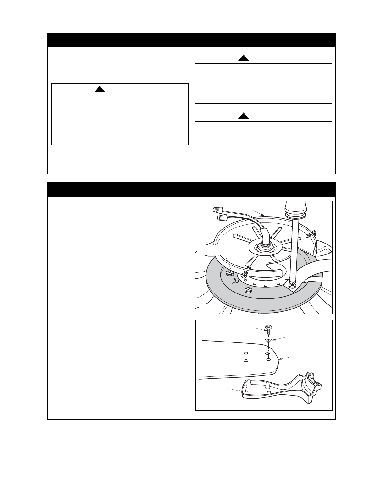
Figure 2
Figure 1
If your fan is to replace an existing ceiling light fixture,
turn electricity off at the main fuse box at this time and
remove the existing light fixture.
Your new ceiling fan will require a grounded electrical
supply line of 120 volts AC, 60 Hz, 15 amp circuit.
The outlet box must be securely anchored and
capable of withstanding a load of at least 50 pounds.
To avoid fire or shock, follow all wiring instructions
carefully. Any electrical work not described in these
instructions should be done or approved by a
licensed electrician.
Turning off wall switch is not sufficient. To avoid
possible electrical shock, be sure electricity is
turned off at the main fuse box before wiring. All
wiring must be in accordance with National and
Local codes and the ceiling fan must be properly
grounded as a precaution against possible electrical
shock.
WARNING
!
WARNING
!
To reduce the risk of fire, electric shock, or
personal injury, mount fan to outlet box marked
“Acceptable for Fan Support of 22.7 kg. (50 lbs.)
or less”, and use screws supplied with outlet box.
Most outlet boxes commonly used for support of
light fixtures are not acceptable for fan support
and may need to be replaced. Consult a qualified
electrician if in doubt.
WARNING
!
ETL Model No.: CF788
2. Mount blade flanges (supplied with fan) to fan
blades (sold separately) using four #10-24 x 12mm
washer head blade screws and four 16mm flat
washers (supplied with fan) (Figure 2).
NOTE: Some accessory blades available are
supplied with shorter screws. These shorter
screws MUST be used to assemble the blades to
flanges.
1. Rotate the motor hub to align the hub notch area
over each of the five screws which is holding the
shipping retainer to the motor assembly. One by
one unscrew each screw and discard screw and
shipping retainer (Figure 1).
MOTOR
HUB
REMOVE SHIPPING RETAINER
BY REMOVING 5 SCREWS
r
e
b
b
u
l
a
R
t
s
e
n
v
I
S
o
e
s
r
m
o
o
e
f
L
R
e
r
a
!
r
a
B
i
t
E
i
T
d
u
T
r
Y
a
Q
O
e
c
!
N
J
s
A
i
a
T
D
l
a
O
b
N
m
E
d
n
A
s
t
n
u
o
M
g
n
i
k
a
r
a
c
P
a
a
.
P
o
i
t
a
l
o
p
o
o
L
r
n
m
o
i
c
o
a
.
l
a
G
t
n
s
e
n
I
D
a
L
s
e
e
t
D
r
s
e
t
n
A
s
#10-24 x 12mm WASHER
HEAD BLADE SCREW
(4 per blade/flange)
BLADE FLANGE
FLAT WASHER 16 mm OD
(4 per blade/flange)
FAN BLADE
 Loading...