

Emerson CF787CK01, CF787AW01, CF787AP01, CF787BS01, CF787GBZ01 Owner's Manual
...
Part No. F40BP73770005 Form No. BP7377-5
U.L. Model No.: CF787
READ AND SAVE THESE INSTRUCTIONS
Damp Location
Ceiling Fan Owner's Manual
CF787AW01 - Summer White
CF787AP01 - Antique Pewter
CF787BS01 - Brushed Steel
CF787CK01 - Chalk
CF787GBZ01 - Gilded Bronze
CF787GES01 - Golden Espresso
CF787ORB01 - Oil Rubbed Bronze
CF787VNB01 - Venetian Bronze
Model Numbers
CARRERA GRANDE
™
54”, 60” or 72” Fan Blades
Not Included
Net Weight: 25.3 Lbs.
WARNING: To avoid fire, shock, and serious personal injury, follow these instructions.
Safety Instructions
1. Read your owner’s manual carefully and keep it for future reference.
2. Before servicing or cleaning unit, switch power off at service panel and lock service panel
disconnecting means to prevent power from being switched on accidentally. When the service
disconnecting means cannot be locked, securely fasten a warning device, such as a tag, to the
service panel.
3. Be careful of the fan and blades when cleaning, painting, or working near the fan. Always turn off
the power to the ceiling fan before servicing.
4. Do not put anything into the fan blades while they are turning.
5. Do not operate reversing switch until fan blades have come to a complete stop.
Additional Safety Instructions for Installation
1. To avoid possible shock, be sure electricity is turned off at the fuse box before wiring, and do not
operate fan without blades.
2. All wiring must be in accordance with the National Electrical Codes “ANSI/NFPA 70-2008” and
Local Electrical Codes. Use the National Electrical Code if Local Codes do not exist. The ceiling
fan must be grounded as a precaution against possible electrical shock. Electrical installation
should be made or approved by a licensed electrician.
3. The outlet box and joist must be securely mounted and capable of reliably supporting at least 50
pounds. Use only U.L. outlet boxes listed as “Acceptable for Fan Support of 50 lbs or less”, and
use the mounting screws provided with the outlet box. Most outlet boxes commonly used for
support of light fixtures are not acceptable for fan support and may need to be replaced. Consult
a qualified electrician if in doubt.
4. The downrod furnished with the fan provides the minimum recommended floor to fan blade
clearance for an 8 foot ceiling.
5. The fan must be mounted with the fan blades at least 7 feet from the floor to prevent accidental
contact with the fan blades.
6. Follow the recommended instructions for the proper method of wiring your ceiling fan. If you do
not know enough about electrical wiring, have your fan installed by a licensed electrician.
NOTE: This fan is suitable for use with solid-state speed controls.
WARNING: To reduce the risk of fire or electric shock, this fan should only be used with fan speed
control, Model No. SW46/UL Model No. UDC9020 manufactured by Rhine Electric Co., Ltd.
WARNING: To avoid fire, shock or injury, do not use an Emerson or any other brand of control not
specifically approved for this fan.
WARNING: This product is designed to use only those parts supplied with this product and/or any
accessories designated specifically for use with this product by Emerson Electric Co. Substitution
of parts or accessories not designated for use with this product by Emerson Electric Co. could
result in personal injury or property damage.
WARNING: To reduce the risk of personal injury, do not bend the blade flange when installing the
blade flanges, balancing the blades or cleaning the fan. Do not insert foreign objects in between
rotating fan blades.
WARNING: To reduce the risk of electrical shock, this fan must be installed with an isolating wall
control/switch.
WARNING
2
!
DATE CODE:
The date code of this fan may be found on the box, stamped in ink on a white label.
You should record this data above and keep it in a safe place for future use.
U.L. Model No.: CF787
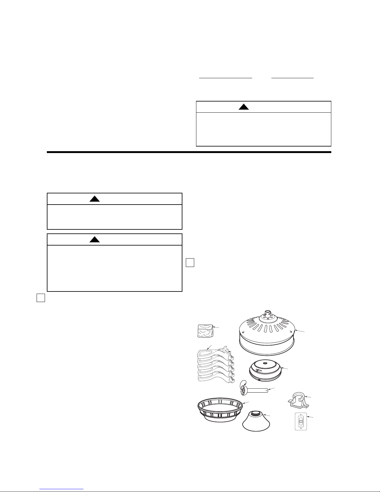
1. Check to see that you have received the following
parts:
NOTE: If you are uncertain of part description,
refer to exploded view illustration.
a. Fan motor assembly
b. One switch housing assembly
c. One ceiling cover
d. Five blade flanges
e. One hanger ball/4.5” downrod assembly
f. One hanger bracket
g. One coupling cover
h. One 4-speed slide wall control
i. One loose parts bag containing:
1. Twenty-one M5 x 12mm washer head
blade screws
2. Twenty-one 16mm OD flat washer
3. One M4 x 12mm flat head screw
4. One M6 x 14mm pan head screw with
lockwasher
5. Four wire connectors
6. Two threaded studs
7. Two knurled knobs
This Manual Is Designed to Make it as Easy as Possible for You to Assemble,
Install, Operate and Maintain Your Ceiling Fan
Tools Needed for Assembly
One Phillips head screwdriver One stepladder
One wire stripper
MATERIALS
Wiring outlet box and box connectors must be of type
required by the local code. The minimum wire would
be a 3-conductor (2-wire with ground) of the following
size:
3
Installed Wire Length Wire Size A.W.G.
Up to 50 ft. 14
50-100 ft. 12
Unpacking Instructions
For your convenience, check-off boxes are provided next to each step. As each step is completed, place a
check mark in the box. This will insure that all steps have been completed and will be helpful in finding
your place should you be interrupted.
Before assembly your ceiling fan, refer to section on
proper method of wiring your fan (page 8). If you feel
you do not have enough wiring knowledge or
experience, have your fan installed by a licensed
electrician.
Do not install or use fan if any part is damaged or
missing. Call Toll-Free:
1-800-654-3545
This product is designed to use only those parts
supplied with this product and/or any accessories
designated specifically for use with this product by
Emerson Electric Co. Substitution of parts or
accessories not designated for use with this product
by Emerson Electric Co. could result in personal
injury or property damage.
WARNING
!
WARNING
!
WARNING
!
U.L. Model No.: CF787
THESE FAN MODELS ARE SUITABLE FOR DAMP LOCATIONS SUCH AS COVERED PORCHES,
COVERED PATIOS, AND COVERED DECKS... ANYWHERE THERE IS A ROOF OVERHEAD.
8. Two lockwashers
9. One clevis pin
10. One hairpin clip
11. One balance kit
NOTE: Place the parts from the loose parts bags
in a small container to keep them from being lost.
If any parts are missing, contact your local
retailer or catalog outlet for replacement before
proceeding.
2. Remove the fan assembly from the protective
plastic bag. Place the fan assembly into the upper
foam pad with the bottom of the motor facing up.
The upper foam pad serves as a holder for the fan
during the first stages of assembly.
I. LOOSE
PARTS BAG
D. BLADE
FLANGES
C. CEILING
COVER
E. HANGER BALL/
DOWNROD ASSEMBLY
G. COUPLING
COVER
A. FAN MOTOR
ASSEMBLY
B. SWITCH HOUSING
ASSEMBLY
4
3
2
1
0
F. HANGER
BRACKET
H. WALL
CONTROL
4
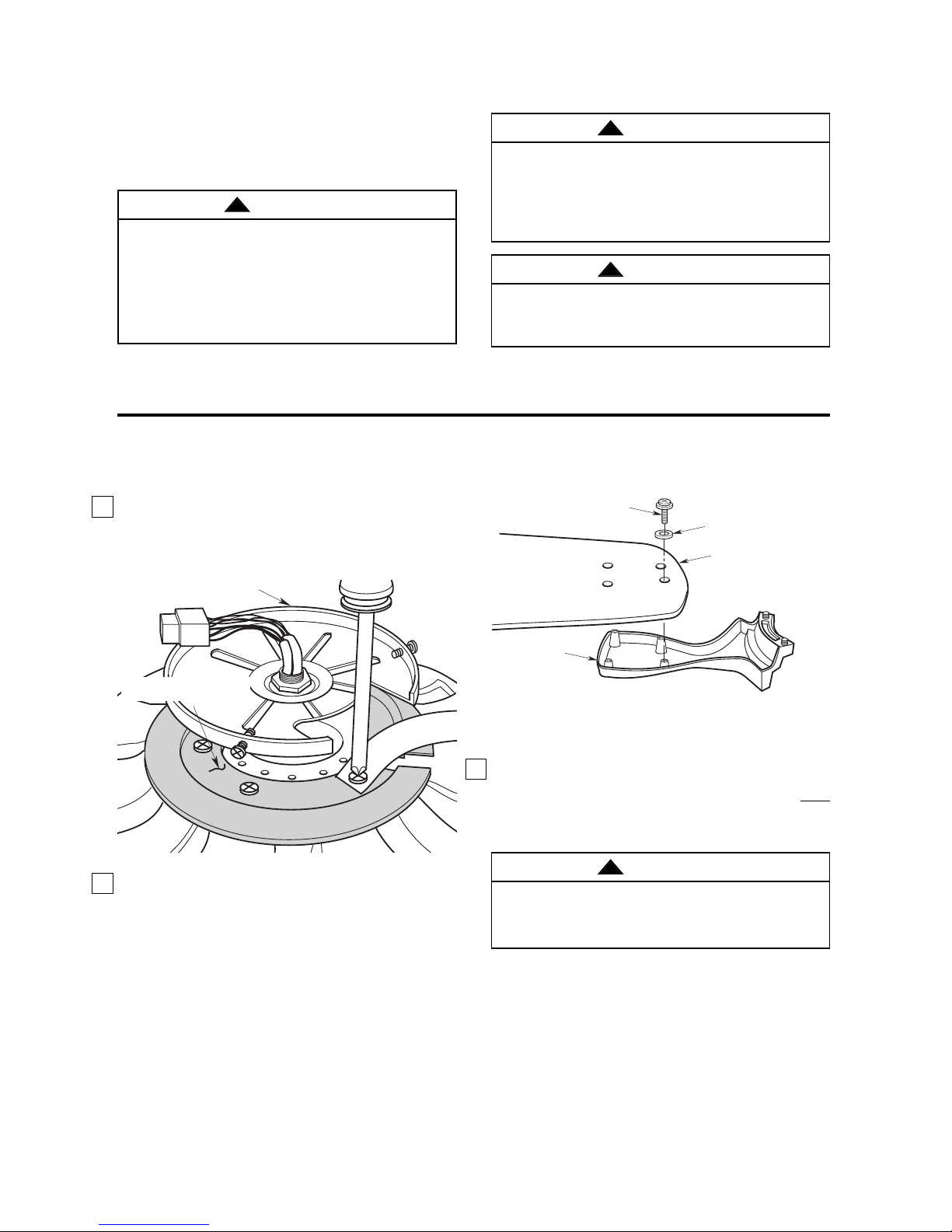
1. Rotate the motor hub to align the hub notch area
over each of the five screws which is holding the
shipping retainer to the motor assembly. One by
one unscrew each screw and discard screw and
shipping retainer (Figure 1).
To reduce the risk of personal injury, do not bend the
blade flange when installing the blade flanges,
balancing the blades or cleaning the fan. Do not
insert foreign objects in between rotating fan blades.
WARNING
!
Figure 2
Figure 1
2. Mount blade flanges (supplied with fan) to fan
blades (sold separately) using four M5 x 12mm
washer head blade screws and four 16mm flat
washers (supplied with fan) (Figure 2).
NOTE: Some accessory blades available are
supplied with shorter screws. These shorter
screws MUST be used to assemble the blades to
flanges.
3. Loosely attach one blade/flange assembly to the
motor hub by securing the two M6 x 14mm captive
pan head screws. Make sure the screws are NOT
tightened (Figure 3). Repeat this procedure for
other four blade assemblies.
How to Put Your Ceiling Fan Together
Electrical Requirements
If your fan is to replace an existing ceiling light fixture,
turn electricity off at the main fuse box at this time and
remove the existing light fixture.
Your new ceiling fan will require a grounded electrical
supply line of 120 volts AC, 60 Hz, 15 amp circuit.
The outlet box must be securely anchored and
capable of withstanding a load of at least 50 pounds.
To avoid fire or shock, follow all wiring instructions
carefully. Any electrical work not described in these
instructions should be done or approved by a
licensed electrician.
Turning off wall switch is not sufficient. To avoid
possible electrical shock, be sure electricity is
turned off at the main fuse box before wiring. All
wiring must be in accordance with National and
Local codes and the ceiling fan must be properly
grounded as a precaution against possible electrical
shock.
WARNING
!
WARNING
!
To reduce the risk of fire, electrical shock, or
personal injury, mount fan to outlet box marked
“Acceptable for Fan Support of 50 lbs or less”, and
use screws supplied with outlet box. Most outlet
boxes commonly used for support of light fixtures
are not acceptable for fan support and may need to
be replaced. Consult a qualified electrician if
in doubt.
WARNING
!
U.L. Model No.: CF787
NOTE: Take care not to scratch fan housing when
installing blades.
MOTOR HUB
M5 x 12mm WASHER
HEAD BLADE SCREW
(4 per blade/flange)
BLADE FLANGE
FLAT WASHER 16 mm OD
(4 per blade/flange)
FAN BLADE
REMOVE SHIPPING RETAINER
BY REMOVING 5 SCREWS
a
P
r
e
b
i
t
b
a
l
u
l
a
R
t
s
e
p
n
o
v
I
S
o
e
s
r
m
o
o
o
e
L
f
L
r
R
e
r
a
!
r
a
B
i
t
E
i
T
d
u
T
r
Y
a
Q
O
e
c
!
N
J
s
A
i
a
T
D
l
a
O
b
N
m
E
d
n
A
s
t
n
u
o
M
g
n
i
k
a
r
a
c
P
a
.
n
m
o
i
c
o
a
.
l
a
G
t
n
s
e
n
o
I
D
a
L
s
e
e
t
D
r
s
o
e
t
n
A
s
5
Figure 4
4. The blade flanges have an interlocking feature that
must be fully engaged before tightening the screw.
Make sure all the flanges are properly engaged
and then tighten the flange screws. If one of the
flanges does not seat properly on the motor hub,
loosen the adjacent flange screws, re-engage and
reseat the flanges, then tighten the screws again.
Figure 3
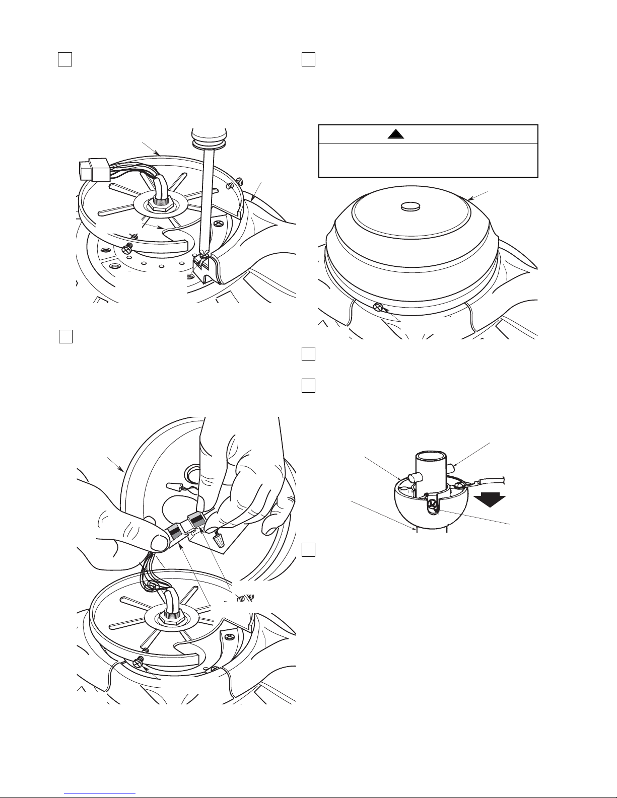
5. Remove and retain the three switch housing
mounting screws (Figure 4) from the switch
housing plate. Engage the connector of the switch
housing assembly with the motor connector
(Figure 4). The two connectors are keyed and
color-coded and must be mated correctly (color-tocolor) before they can be engaged. Make sure the
connector latch closes properly.
8. Remove the hanger ball by loosening the setscrew
in the hanger ball until the ball falls freely down the
downrod (Figure 6). Remove the pin from the
downrod, then remove the hanger ball. Retain the
pin and hanger ball for reinstallation in Step 9.
9. Separate, untwist and unkink the three 80” motor
leads. Route the motor lead wires through the
downrod. Remove the upper setscrew from the
motor coupling. Align the clevis pin holes in the
downrod with the holes in the motor coupling.
Install the clevis pin and secure with the hairpin clip
(Figure 7). The clevis pin must go through the
holes in the motor coupling and the holes in the
downrod. Be sure to push the straight leg of the
hairpin clip through the hole near the end of the
clevis pin until the curved portion of the hairpin clip
snaps around the clevis pin. The hairpin clip must
be properly installed to prevent the clevis pin from
working loose. Pull on the downrod to make sure
the clevis pin is properly installed. Reinstall the
upper setscrew in the motor coupling. Check that
the lower setscrew is tightened securely (Figure 7).
Figure 5
To avoid possible fire or shock, do not pinch wires
between the switch cup assembly and the switch
cup plate.
WARNING
!
Figure 6
6. Position the switch housing assembly on the
switch housing plate and align the holes in the
switch housing assembly with the holes in the
plate. Secure the switch housing assembly by
installing the three M4 x 12mm flat head screws
(supplied) (Figure 5).
7. Carefully turn partially assembled fan upside down
and place in styrofoam form carton, in preparation
for final installation.
U.L. Model No.: CF787
MOTOR HUB
MOTOR HUB
NOTCHED AREA
M6 x 14mm CAPTIVE PAN
HEAD SCREW (2 per
blade/flange assembly)
BLADE/FLANGE
ASSEMBLY
M4 x 12mm FLAT HEAD
SCREW (3)
SWITCH HOUSING
ASSEMBLY
SWITCH HOUSING
ASSEMBLY
SWITCH HOUSING
CONNECTOR
MOTOR CONNECTOR
SWITCH HOUSING
MOUNTING SCREW (3)
HANGER
BALL
DOWNROD
PIN
SETSCREW
 Loading...