

Emerson CF712AB02, CF712ORB02, CF712AW02, CF712WORB02, CF712BS02 Owner's Manual
...
Questions, problems, missing parts: Before returning to the store call
Emerson Electric Customer Service - 8 a.m. - 6 p.m., Eastern, Monday-Friday
Part No. F40BP73000007 Form No. BP7300-7
Revision: 150226 U.L. Model No.: 52-ANT
www.emersonfans.com
CF712AB02
Antique Brass
CF712AW02
Summer White
CF712BS02
Brushed Steel
Net Weight: 19.0 Lbs.
READ AND SAVE THESE INSTRUCTIONS
1-800-654-3545
PRO SERIES™
50” Ceiling Fan Owner's Manual
CF712ORB02
Oil Rubbed Bronze
with Amber Scavo Glass
CF712WORB02
Oil Rubbed Bronze with Opal
Matte Glass
CF712WW02
Appliance White
Model Numbers
• Español - página 29
• Français - page 57
2
U.L. Model No.: 52-ANT
Safety Instructions
TO REDUCE THE RISK OF FIRE, ELECTRICAL SHOCK,
OR INJURY TO PER S O N S , O B S ERVE THE
FOLLOWING:
a. Use this unit only in a manne r intended by t he
manufacturer. If you have questions, contact the
manufacturer.
b. Before servicing or cleaning unit, switch power off
at service pa n e l a n d l o c k se rvice panel
disconnecting means to prevent power from being
switche d o n a c c i d entally . W h e n t h e service
disconnecting means cannot be locked, securely
fa sten a wa rning devi ce, s uch a s a t ag, t o th e
service panel.
WARNING
!
Additional Safety Instructions for Installation
1. To avoid possible shock, be sure electricity is turned
off at the fuse box before wiring, and do not operate
fan without blades.
2. All wiring must be in accordance with the National
El e ctrical Code “AN S I/NFPA 70- 2 014” a n d Loca l
Electrical Codes. Use the National Electrical Code if
Local Codes do not exist. The ceiling fan must be
grounded as a precaution against possible electrical
sh ock. E lectri c al in stalla tion s hould be made or
approved by a licensed electrician.
3. The outlet box and joist must be securely mounted
and capable of reliably supporting at least 50 pounds.
Use only U.L. outlet boxes listed as “Acceptable for
Fan Support of 22.7 kg. (50 lbs.) or less”, and use the
mounting scr e w s provide d wi t h th e ou t l e t box.
Most outlet boxes commonly used for support of light
fixtures are not acceptable for fan support and may
need to be replaced. Consult a qualified electrician if
in doubt.
4. The down rod fu rnished w ith th e fan provides the
minimum recommended floor to fan blade clearance
for an 8 foot ceiling.
5. The fan must be mounted with the fan blades at least
7 feet from the floor to prevent accidental contact with
the fan blades.
6. Follow the recommended instructions for the proper
method of wiring your ceiling fan. If you do not know
enough about electrical wiring, have your fan installed
by a licensed electrician.
WARNING: To reduce the risk of electrical shock, this
fan mu s t be installe d with an iso l a t i n g wa l l
control/switch.
WARNING: To avoid fire, shock or injury, do not use an
Emerson or any other brand of control not specifically
approved for this fan.
WARNING: This product is designed to use only those
parts supplied with this product and/or any accessories
designated specifically for use this product by Emerson
Electric Co. Substitution of parts or accessories not
designated for use with this product by Emerson could
result in personal injury or property damage.
WARNING: To reduce the risk of personal injury, do not
bend the blade flange when installing the blade flanges,
balancing the blades or cleaning the fan. Do not insert
foreign objects in between rotating fan blades.
NOTE: All setscrews must be checked and re-tightened
where necessary before installation.
1. Read your owner’s manual carefully and keep it for
future reference.
2. Be car eful of the fan and bla des w h en cl eaning ,
painting, or working near the fan. Always turn off the
power to the ceiling fan before servicing.
3. Do not put anything into the fan blades while they are
turning.
4. Do not operate reversing switch until fan blades have
come to a complete stop.
DATE CODE:
The date code of this fan may be found on the box, stamped in ink on a white label. You should
record this data above and keep it in a safe place for future use.
READ AND SAVE THESE INSTRUCTIONS
Table of Contents
Section Page
Safety Instructions . . . . . . . . . . . . . . . . . . . . . . . . . . . . . . . .2
1. Unpacking Instructions . . . . . . . . . . . . . . . . . . . . . . . . .3-4
2. Electrical Requirements . . . . . . . . . . . . . . . . . . . . . . . . . .4
3. Removal of the Hanger Bracket . . . . . . . . . . . . . . . . . . . .5
4. Installing the Hanger Ball/Downrod Assembly
(Standard) 6-7
5. Installing the Ceiling Cover on the Fan Motor Housing
(Close-to-Ceiling)
. . . . . . . . . . . . . . . . . . . . . . . . . . . .8-9
6. How to Hang Your Ceiling Fan . . . . . . . . . . . . . . . . .10-11
7. Hanging the Ceiling Fan (Standard) . . . . . . . . . . . . . . . .11
8. Hanging the Ceiling Fan
(Close-to-Ceiling) . . . . . . . . . . . .12
9. How to Wire Your Ceiling Fan . . . . . . . . . . . . . . . . . .13-14
10. Installing the Ceiling Cover . . . . . . . . . . . . . . . . . . . . . .15
Section Page
11. Installing the Fan Blades . . . . . . . . . . . . . . . . . . . . . . . .16
12. Installing the Light Fitter . . . . . . . . . . . . . . . . . . . . . .17-20
13. Using Your Ceiling Fan . . . . . . . . . . . . . . . . . . . . . . . . .21
14. Maintenance . . . . . . . . . . . . . . . . . . . . . . . . . . . . . . . . .22
15. Accessories . . . . . . . . . . . . . . . . . . . . . . . . . . . . . . . . . .22
16. Instruction to the User . . . . . . . . . . . . . . . . . . . . . . . . . .22
1
7. Trouble Shooting . . . . . . . . . . . . . . . . . . . . . . . . . . . . . .23
18. Repair Parts . . . . . . . . . . . . . . . . . . . . . . . . . . . . . . .24-25
Ceiling Fan Limited Warranty . . . . . . . . . . . . . . . . . . . . . . .27
Spanish . . . . . . . . . . . . . . . . . . . . . . . . . . . . . . . . . . . . . . . .29
French . . . . . . . . . . . . . . . . . . . . . . . . . . . . . . . . . . . . . . . . .57
1. Unpacking Instructions
3
emersonfans.com
Please contact 1-800-654-3545 for further assistance
U.L. Model No.: 52-ANT
This pro duc t is de signed to use o nly tho se parts
supplied with this product and/or any accessories
designated specifically for use with this product by
Emerson E l e c t ric Co. S u b s t itution o f p a r ts or
accessories not designated for use with this product
by Emerson Electric Co. could result in personal injury
or property damage.
WARNING
!
Do not install or use fan if any part is damaged or
missing. Call Toll-Free:
1-800-654-3545
WARNING
!
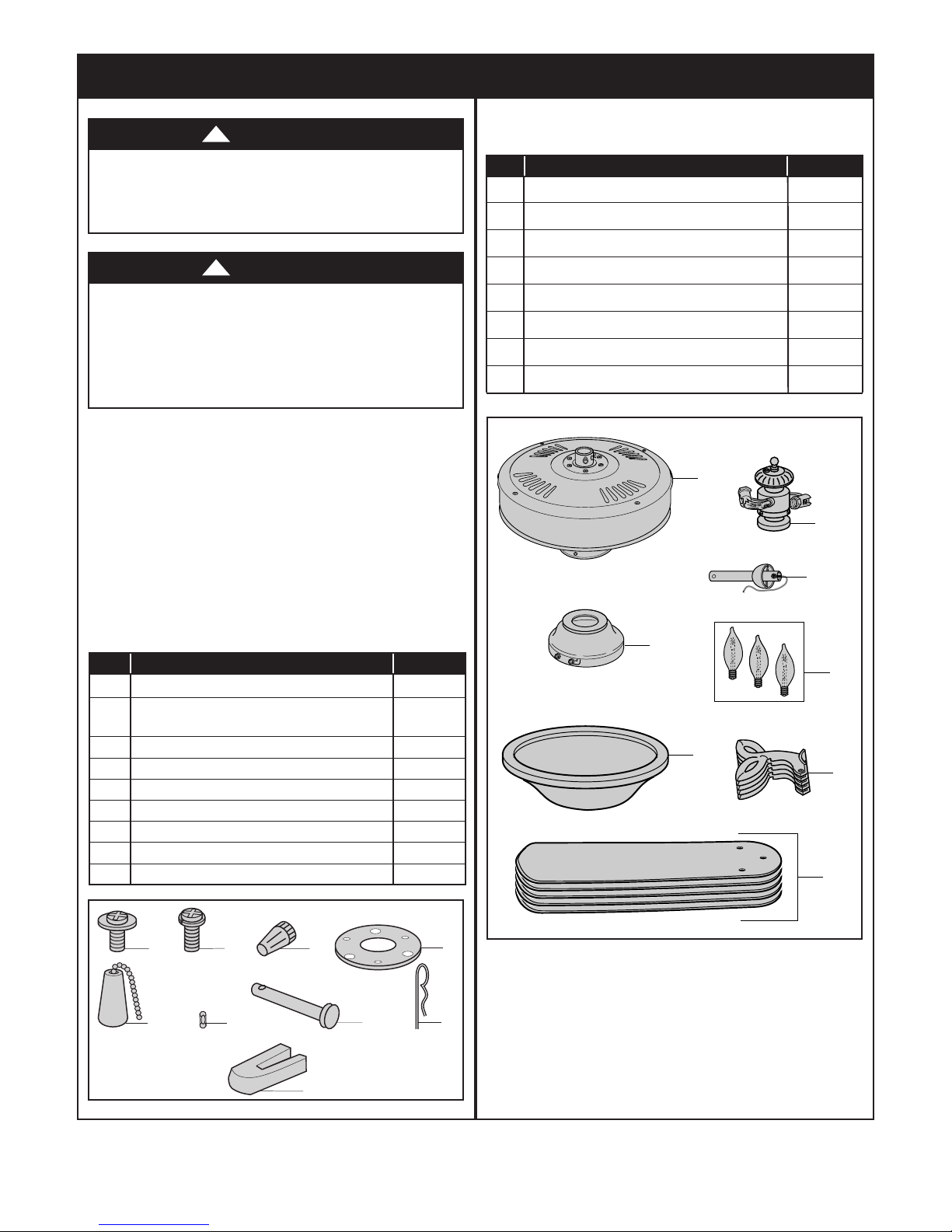
1.1
Open car t o n contai n i ng fan. R e m ove top h a l f of
styrofoam unit. Remove parts and check to see that you
have received the following parts:
NOTE: If you are uncertain of part description, refer
to exploded view illustration.
NOTE: Place the parts from the loose parts bags in
a small container to keep them from being lost.
If a n y par t s ar e mis s ing, c all 1 -800 - 654- 3 545
for replacement parts before proceeding.
A
B
C
D
E
F
G
H
PACKAGE CONTENTS
1
2
3
7
8
4
5
6
9
HARDWARE CONTENTS
Part Description Quantity
1 M5 x 16mm Washer Head Blade Screws 16
2 Phillips Round Head Flange Screw
with Lockwasher 1
3 Wire Connectors, 12 ga. 3
4 Rubber Gasket 1
5 Wood Pendants 2
6 Couplings 2
7 Clevis Pin 1
8 Hairpin Clip 1
9 Blade Balance Kit 1
1.2
Remove the fan housing assembly from the protective
plastic bag. Turn the upper styrofoam pad over and
carefully place the fan motor assembly into the recess
in the pad with the top of the motor facing up.
Part Description Quantity
A Fan Motor Assembly 1
B Ceiling Cover with Hanger Bracket 1
C Glass Bowl 1
D Light Fitter 1
E Hanger Ball / 4.5” Downrod Assembly 1
F 60-Watt (max.) Candelabra Base Bulbs 3
G Blade Flanges 5
H Fan Blades 5
4
U.L. Model No.: 52-ANT
The outlet box must be securely anchored and capable
of withstanding a load of at least 50 pounds.
If your fan is to replace an existing ceiling light fixture,
turn electricity off at the main fuse box at this time and
remove the existing light fixture.
B
efore assembling your ceiling fan, refer to section on
proper method of wiring your fan (page 13). If you feel
you do not h a v e e n o ugh wiring k n o w l edge or
experience, have your f an installed b y a licensed
electrician.
WARNING
!
This Manual Is Designed to Make it as Easy as Possible for You to Assemble,
Install, Operate and Maintain Your Ceiling Fan
Tools Needed for Assembly
One Phillips head screwdriver One stepladder
One 1/4” blade screwdriver One wire stripper
Three wire connectors (supplied).
Materials
Wiring outlet box and box connectors must be of type
required by the local code. The minimum wire would be
a 3-conductor (2-wire with ground) of following size:
Installed Wire Length Wire Size A.W.G.
Up to 50 ft. 14
50-100 ft. 12
2. Electrical Requirements
Your new ceiling fan will require a grounded electrical
supply line of 120 volts AC, 60 Hz, 15 amp circuit.
To reduce the risk of fire, electric shock, or personal
injury, mount fan to outlet box marked “Acceptable for
Fan Support of 22.7 kg. (50 lbs.) or less”, and use
screws supplied with outlet box. Most outlet boxes
commonly used for support of light fixtures are not
acceptab l e fo r fan sup p o r t and may need to b e
replaced. Consult a qualified electrician if in doubt.
WARNING
!
Turning off wall switch is not sufficient. To avoid
possible electrical shock, be sure electricity is turned
off at the main fuse box before wiring. All wiring must
be in accordance with National and Local codes and
the c e i l i n g fan must b e properly grounded as a
precaution against possible electrical shock.
WARNING
!
To avoid fire or shock, follow all wiring instructions
carefully.
Any e l e c t r ical w o r k no t de s cribed i n th e s e
instructions should be done or approved by a licensed
electrician.
WARNING
!
1. Unpacking Instructions (Continued)
Plea s e ca ll Emer s o n techn i cal sup p o rt at
1-800-654-3545 if you have any questions about
installation and operation of this ceiling fan.
Controls Sold Separately
SW46 Wall Control and SW90 Wall Control (both sold
separately) may be used with this 50” PRO Series
Ceiling Fan. Controls are recommended for indoor use
only.
5
emersonfans.com
Please contact 1-800-654-3545 for further assistance
U.L. Model No.: 52-ANT
IMPORTANT
Your ce i l ing fan is de s igne d to be in s tall e d e i ther in th e s t a ndar d m a nner , o r in th e
close-to-the-ceiling manner. Using the standard method, the hanger ball/downrod assembly will suspend
the fan several inches below the ceiling cover. Using the close-to-the-ceiling method, the ceiling cover
i
nstalls directly on the fan motor housing, thus mounting the fan 3-1/2 inches closer to the ceiling than the
standard method. In no case should the fan blades be lower than seven feet above the floor. Depending
on your desired mounting method, proceed to “INSTALLING HANGER BALL/DOWNROD ASSEMBLY” for
standard mounting, or to “INSTALLING CEILING COVER ON FAN MOTOR HOUSING” for close-to-theceiling mounting.
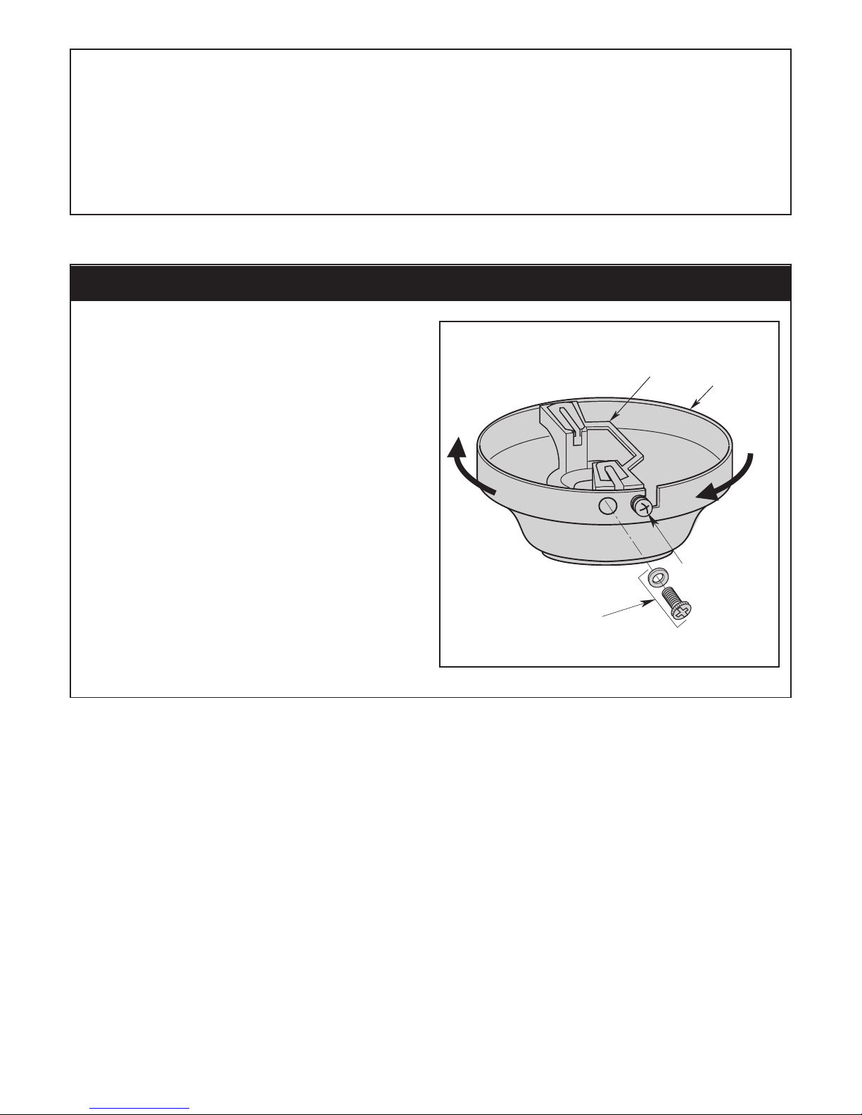
3. Removal of the Hanger Bracket
REMOVE AND RETAIN
TWO SCREWS AND
LOCKWASHERS
LOOSEN THE TWO
SCREWS IN THE
KEYHOLE SLOTS
CEILING
COVER
HANGER
BRACKET
ROTATE CEILING COVER
COUNTER-CLOCKWISE
TO REMOVE THE
HANGER BRACKET
3.1
Loosen the two screws in the keyholes slots of the
ceiling cover.
Remo v e and ret a in th e oth e r two scr e w s an d
lockwashers (Figure 1).
Turn the ceiling cover and remove the hanger bracket.
Figure 1
6
U.L. Model No.: 52-ANT
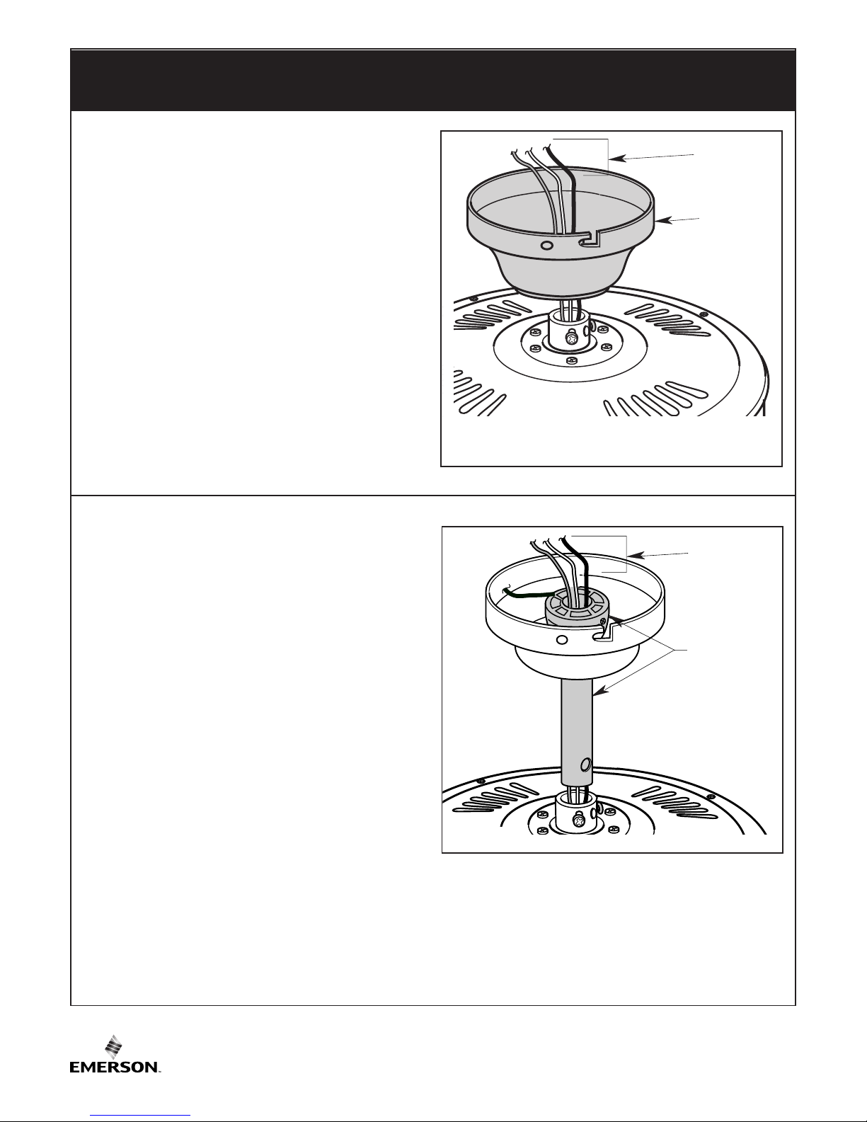
4. Installing the Hanger Ball/Downrod Assembly
(For Standard Mounting)
4.2
Separate, untwist and unkink the three motor leads.
Route the motor leads through the hanger ball/downrod
assembly (Figure 3).
HANGER
BALL/4.5"
DOWNROD
ASSEMBLY
THREE 42"
MOTOR LEADS
Figure 3
THREE 42"
MOTOR LEADS
CEILING
COVER
4.1
Pass the 42" motor leads through the opening in the
c
eiling cover.
Be sure the cover is oriented correctly (Figure 2).
Figure 2
7
emersonfans.com
Please contact 1-800-654-3545 for further assistance
U.L. Model No.: 52-ANT
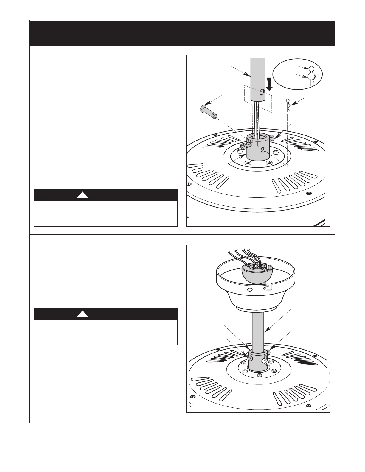
DOWNROD
CLEVIS
PIN
HAIRPIN
CLIP
MOTOR
COUPLING
H
AIRPIN
C
LIP
CLEVIS
P
IN
LOOSEN
S
ETSCREWS (2)
Figure 4
4.3
Loosen the two setscrews in the motor coupling.
Place the hanger ball/downrod assembly into the motor
coupling, aligning the clevis pin holes in the downrod
w
ith the holes in the motor coupling (Figure 4).
The clevis pin must go through the holes in the motor
coupling and the holes in the downrod.
Be sure to push the straight leg of the hairpin clip
through the hole near the end of the clevis pin until the
curved portion of the hairpin clip snaps around the
clevis pin.
The hairpin clip must be properly installed to prevent
the clevis pin from working loose.
Pull on the hanger ball to make sure the clevis pin is
properly installed.
4. Installing the Hanger Ball/Downrod Assembly
(For Standard Mounting) (Continued)
MOTOR
COUPLING
HANGER BALL/
DOWNROD
ASSEMBLY
RETIGHTEN
SETSCREW
RETIGHTEN
SETSCREW
4.4
While pulling up on the hanger ball, retighten the two
setscrews (previously loosened) in the motor coupling
to secure the hanger ball/downrod assembly into place
(Figure 5).
NOTE: The setscrews must be properly installed as
described above, or fan wobble could result.
Figure 5
NOTE : For h a ngin g inst r ucti o n s us i n g
Ha n ger Ball/Dow n rod Assembly , See Page 11,
Se c t i o n 6. Hanging the Cei l i n g Fan (Standard
Method Using Hanger Ball/Downrod).
It is critical that the clevis pin in the motor coupling is
properly installed. Failure to verify that the pin is
properly installed could result in the fan falling.
WARNING
!
It is critical that the setscrews are securely tightened.
Fa i lure t o verif y that the setscr e ws are pro perly
installed could result in the fan falling.
WARNING
!
8
U.L. Model No.: 52-ANT
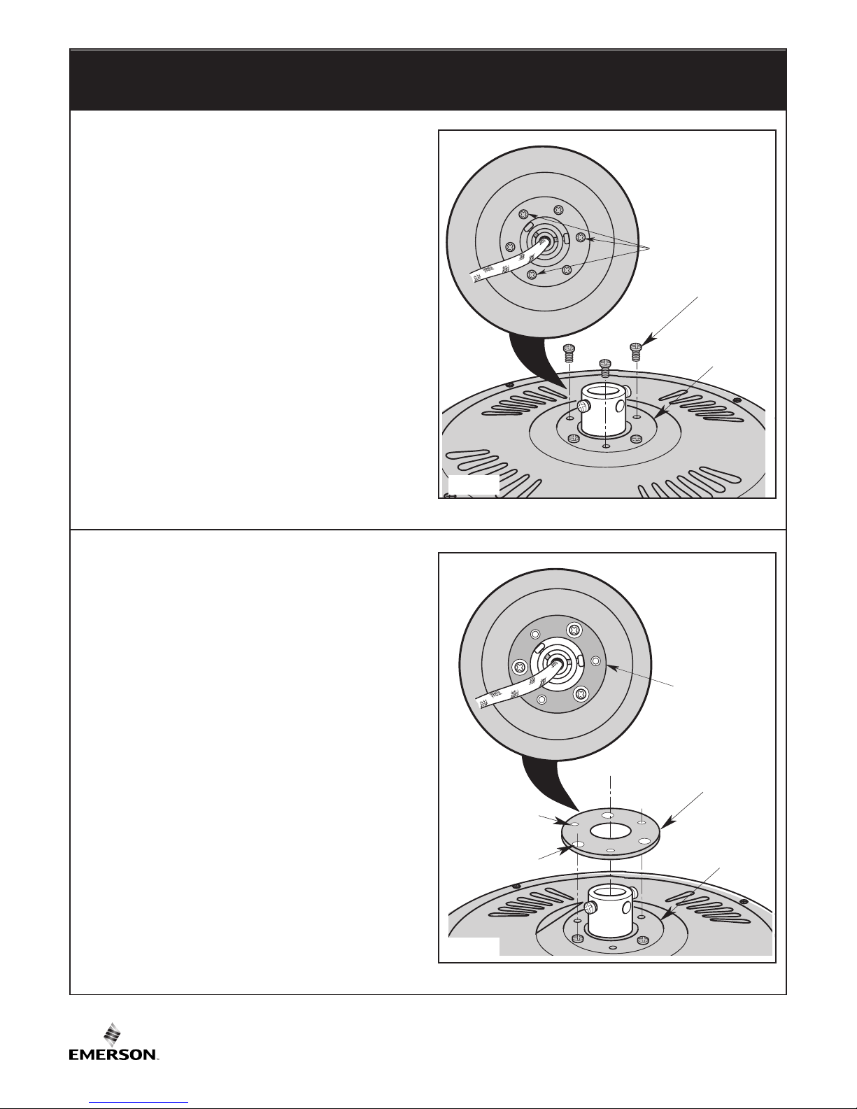
5. Installing the Ceiling Cover on the Fan Motor
Housing (For Close-to-the-Ceiling Mounting)
M
OTOR
HOUSING
SCREWS (3)
MOTOR
HOUSING
REMOVE SCREWS (3)
5.1
Remove three motor housing screws (every other
screw as illustrated) from the top of the motor housing
(
Figure 6).
Retain the three motor housing screws for future use.
Figure 6
RUBBER
GASKET
MOTOR
HOUSING
RUBBER GASKET
LARGE HOLES (3)
RUBBER GASKET
SMALL HOLES (3)
INSTALL
RUBBER
GASKET
5.2
Position the rubber gasket (supplied in parts bag) on
the motor housing.
The three small holes in the gasket should center over
the holes in the motor housing where the three screws
were previously removed (Figure 7).
The three large holes in the gasket should center over
the three screws still installed in the motor housing.
Figure 7
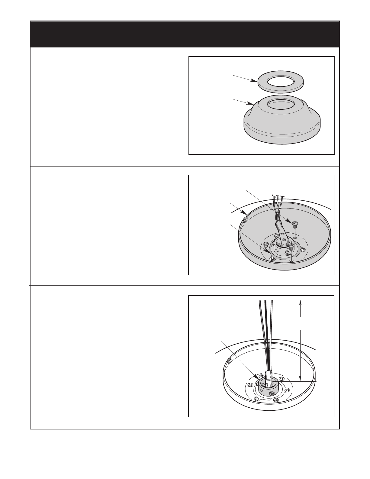
D
ECORATIVE CAP
CEILING COVER
9
emersonfans.com
Please contact 1-800-654-3545 for further assistance
U.L. Model No.: 52-ANT
Figure 8
5. Installing the Ceiling Cover on the Fan Motor
Housing (For Close-to-the-Ceiling Mounting) (Continued)
6 TO 9
INCHES
MOTOR
COUPLING
5.5
The fan comes with blue, black and white leads that are
42” long.
Measure up approximately 6 to 9-inches above the
motor coupling (Figure 10).
Cut off excess leads and strip back insulation 1/2-inch
from ends of leads.
Figure 10
5.3
Gently pry the decorative cap from the ceiling cover
(
Figure 8).
RUBBER GASKET
SCREWS (3)
(Previously Removed)
CEILING COVER
5.4
Align the holes in the ceiling cover with the holes in the
motor housing and secure using the three screws
previously removed in Step 5.1 (Figure 9).
Figure 9
NOTE: For hanging instructions using the Close-tothe- C eili n g Meth o d, See P age 12 , Sect i on 8.
Ha n ging the Ceili n g Fan (Close- t o -the-Ceiling
Method with Ceiling Cover Installed on the Motor
Housing).
 Loading...