

Emerson CF370BS00, CF370BQ00, CF370GRT00, CF370ORB00, CF370SW00 Owner's Manual
READ AND SAVE THESE INSTRUCTIONS
....
MODERN
GEODE
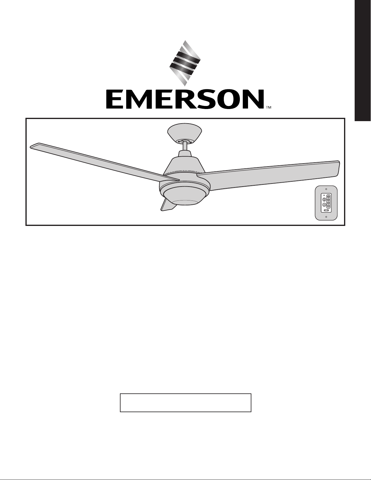
52” Ceiling Fan Owner’s Manual
Model Numbers
CF370BS00
Brushed Steel
CF370BQ00
Barbeque Black
CF370SW00
Satin White
Net Weight: 14.8 Lbs.
CF370GRT00
Graphite
CF370ORB00
Oil Rubbed Bronze
Questions, problems, missing parts: Before returning to the store call
Emerson Electric Customer Service - 8 a.m. - 6 p.m., Eastern, Monday-Friday
• Español - página 33
1-800-654-3545
Part No. F40BP75430000 Form No. BP7543
Revision: 181009 ETL Model No.: CF370
www.emersonfans.com
• Français - page 65
Table of Contents
Section Page
Safety Instructions ................................ 2
1. Unpacking Instructions ..........................3-4
2. Electrical Requirements .......................... 4
3. Ceiling Fan Assembly ...........................5-9
4. How to Hang Your Ceiling Fan ..................10-11
5. How to Wire Your Ceiling Fan ..................12-16
6. Final Assembly ..............................17-19
7. Wall Control Procedures ......................... 20
8. Wall Control Installation ........................21-24
9. Programming the Receiver Operating Frequency ...... 25
READ AND SAVE THESE INSTRUCTIONS
Safety Instructions
WARNING
TO REDUCE THE RISK OF FIRE, ELECTRICAL
SHOCK, OR INJURY TO PERSONS, OBSERVE THE
FOLLOWING:
a. Use this unit only in a manner intended by the
manufacturer. If you have questions, contact the
manufacturer.
b. Before servicing or cleaning unit, switch power
off at service panel and lock service panel
disconnecting means to prevent power from
being switched on accidentally. When the service
disconnecting means cannot be locked, securely
fasten a warning device, such as a tag, to the
service panel.
1. Read your owner’s manual carefully and keep it for
future reference.
2. Be careful of the fan and blades when cleaning,
painting, or working near the fan. Always turn off the
power to the ceiling fan before servicing.
3. Do not put anything into the fan blades while they are
turning.
4. Do not operate reversing switch until fan blades have
come to a complete stop.
Additional Safety Instructions for Installation
1. To avoid possible shock, be sure electricity is turned
off at the fuse box before wiring, and do not operate
fan without blades.
2. All wiring must be in accordance with the National
Electrical Code “ANSI/NFPA 70-2017” and Local
Electrical Codes. Use the National Electrical Code
if Local Codes do not exist. The ceiling fan must be
grounded as a precaution against possible electrical
shock. Electrical installation should be made or
approved by a licensed electrician.
!
Section Page
10. Using Your Ceiling Fan . . . . . . . . . . . . . . . . . . . . . . .25-26
11. Maintenance ................................. 26
12. Accessories ................................. 26
13. Troubleshooting .............................. 27
14. Repair Parts ...............................28-29
15. Energy Efficient Use of Ceiling Fan ............... 30
16. Instructions to the User . . . . . . . . . . . . . . . . . . . . . . . . . 30
Ceiling Fan Limited Warranty ....................... 31
Spanish . . . . . . . . . . . . . . . . . . . . . . . . . . . . . . . . . . . . . . . . 33
French ........................................65
3. The outlet box and joist must be securely mounted
and capable of reliably supporting at least 50 pounds.
Use only U.L. outlet boxes listed as “Acceptable for
Fan Support of 22.7 kg. (50 lbs.) or less”, and use
the mounting screws provided with the outlet box.
Most outlet boxes commonly used for support of light
fixtures are not acceptable for fan support and may
need to be replaced. Consult a qualified electrician if
in doubt.
4. The downrod furnished with the fan provides the
minimum recommended floor to fan blade clearance
for an 8 foot ceiling.
5. The fan must be mounted with the fan blades at least
7 feet from the floor to prevent accidental contact with
the fan blades.
6. Follow the recommended instructions for the proper
method of wiring your ceiling fan. If you do not know
enough about electrical wiring, have your fan installed
by a licensed electrician.
NOTE: This fan is suitable for use with solid-state speed
controls.
NOTE: All set screws must be checked and re-tightened
where necessary before installation.
WARNING
To reduce the risk of electrical shock, this fan must be
installed with an isolating wall control/switch.
To reduce the risk of fire or electrical shock, this fan
should only be used with fan speed control, Model No.
UC7067RA, manufactured by Rhine Electric Co., Ltd.
To avoid fire, shock or injury, do not use an Emerson
or any other brand of control not specifically approved
for this fan.
This product is designed to use only those parts
supplied with this product and/or any accessories
designated specifically for use this product by
Emerson Electric Co. Substitution of parts or
accessories not designated for use with this product
by Emerson could result in personal injury or property
damage.
To reduce the risk of personal injury, do not bend
the blades during installation, balancing the blades
or cleaning the fan. Do not insert foreign objects in
between rotating fan blades.
!
ETL Model No.: CF370
2
1. Unpacking Instructions
6
5
10
8
7
9
4
3
2
1
WARNING
Do not install or use fan if any part is damaged or
missing. Call Toll-Free:
!
1-800-654-3545
WARNING
This product is designed to use only those parts
supplied with this product and/or any accessories
designated specifically for use with this product
by Emerson Electric Co. Substitution of parts or
accessories not designated for use with this product
by Emerson Electric Co. could result in personal injury
or property damage.
!
1.1
Open Carton containing the Fan. Remove top half of
styrofoam unit. Remove Parts and check to see that
you have received the following Hardware and Parts:
NOTE: If you are uncertain of part description, refer
to exploded view illustration.
NOTE: Place the parts from the loose parts bags in
a small container to keep them from being lost. If
any parts are missing, contact your local retailer or
catalog outlet for replacement before proceeding.
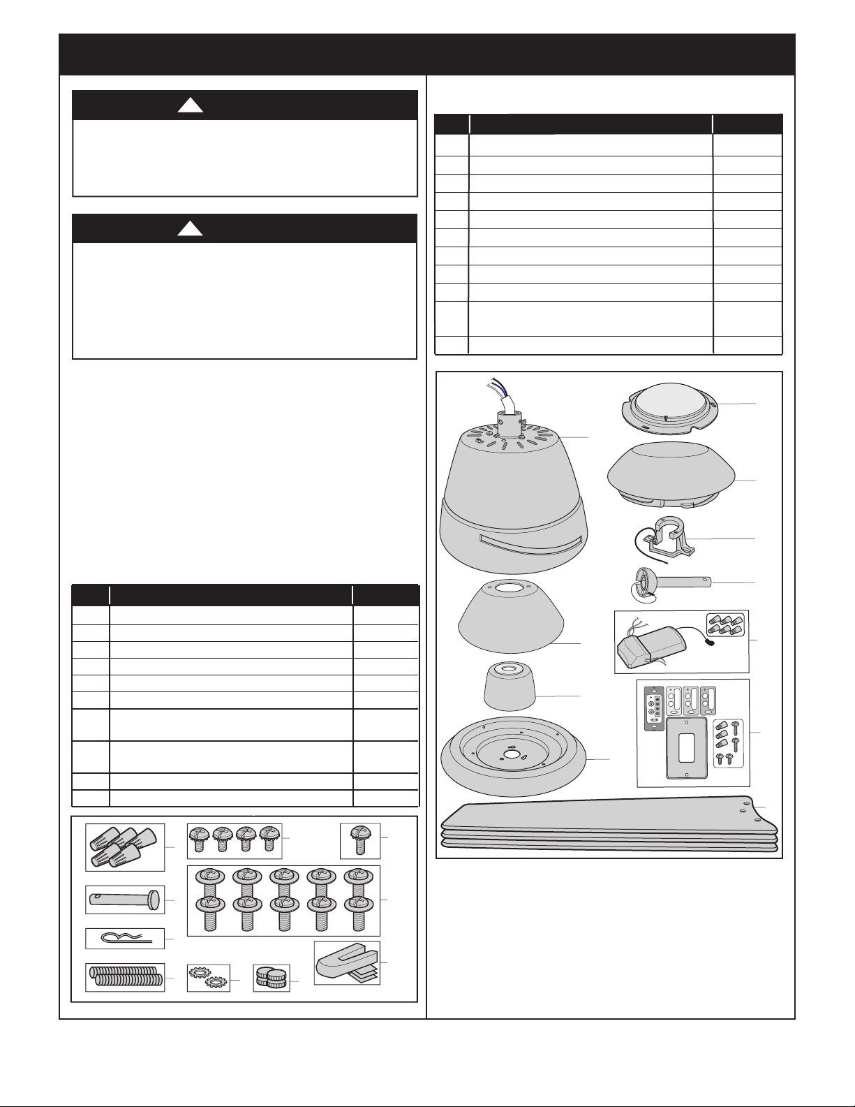
PACKAGE CONTENTS
Part Description Quantity
A Fan Motor Assembly 1
B Ceiling Cover 1
C Coupler Cover 1
D Lower Housing 1
E LED Light Fixture Assembly 1
F Shade 1
G Hanger Bracket 1
H Hanger Ball / 4.5” Downrod Assembly 1
I Receiver with Hardware 1
J 4 Speed Wall Control Transmitter
with Hardware 1
K Fan Blades 3
E
A
F
G
HARDWARE CONTENTS
Part Description Quantity
1 Wire Connectors, 12 ga. 5
2 Clevis Pin 1
3 Hairpin Clip 1
4 Threaded Stud, #8-32 x 1-1/4” 2
5 Lockwashers, External Tooth #8 2
6 Knurled Knobs, #8-32 2
7 #6-32 x 1/4” Truss Head Screws with
Lock Washers 4
8 #6-32 x 3/8” Truss Head Screw with
Lock Washer (spare) 1
9 #10-24 x 11 mm Washer Head Blade Screws 10
10 Blade Balance Kit 1
H
B
C
D
OFF ON
....
OFF ON
I
J
K
1.2
Remove the Fan Motor Assembly from the protective
plastic bag. Place the Fan Motor Assembly onto the
upper foam pad with the bottom of the Fan Motor
Assembly facing up.
The upper foam pad serves as a holder for the Fan
during the first stages of assembly.
3
Please contact 1-800-654-3545 for further assistance
emersonfans.com
ETL Model No.: CF370
1. Unpacking Instructions (Continued)
This Manual Is Designed to Make it as Easy as Possible for You
to Assemble, Install, Operate and Maintain Your Ceiling Fan
Tools Needed for Assembly
One Phillips Head Screwdriver One Stepladder
One 1/4” Blade Screwdriver One Wire Stripper
Materials
Wiring outlet box and box connectors must be of type
required by the local code. The minimum wire would be
a 3-conductor (2-wire with ground) of following size:
Installed Wire Length Wire Size A.W.G.
Up to 50 ft. 14
50-100 ft. 12
2. Electrical Requirements
IMPORTANT: Your ceiling fan will not function
properly, and may be damaged, if used with any
wall dimmer switch or control other than the
Emerson Electric Fan/Light Wall Control supplied
with the fan.
Your New Ceiling Fan will require a Grounded Electrical
Supply Line of 120 volts AC, 60 Hz, 15 amp circuit.
The Outlet Box must be securely anchored and capable
of withstanding a load of at least 50 Pounds.
WARNING
Before assembling your ceiling fan, refer to section
on proper method of wiring your fan (page 12).
If you feel you do not have enough wiring knowledge
or experience, have your fan installed by a licensed
electrician.
!
Controls Sold Separately
SR401 Remote Control (sold separately) may be used
with this 52” Geode Ceiling Fan.
If your Fan is to replace an Existing Ceiling Light
Fixture, turn Electricity Off at the Main Fuse Box at this
time and remove the Existing Light Fixture.
WARNING
Turning off wall switch is not sufficient. To avoid
possible electrical shock, be sure electricity is turned
off at the main fuse box before wiring. All wiring
must be in accordance with National and Local codes
and the ceiling fan must be properly grounded as a
precaution against possible electrical shock.
!
WARNING
To reduce the risk of fire, electric shock, or personal
injury, mount fan to outlet box marked “Acceptable
for Fan Support of 22.7 kg. (50 lbs.) or less”, and
use screws supplied with outlet box. Most outlet
boxes commonly used for support of light fixtures
are not acceptable for fan support and may need to be
replaced. Consult a qualified electrician if in doubt.
ETL Model No.: CF370
!
WARNING
To avoid fire or shock, follow all wiring instructions
carefully.
Any electrical work not described in these
instructions should be done or approved by a licensed
electrician.
Please call Emerson Technical Support at
1-800-654-3545 if you have any questions about
installation and operation of this Ceiling Fan.
4
!
3. Ceiling Fan Assembly
3.1
Slide a Blade through the Fan Motor Assembly Center
Blade Slot.
Mount the Blade to Fan Motor Assembly using Three
#10-24 x 11mm Washer Head Blade Screws (supplied)
(Figure 1).
NOTE: Take care not to scratch Fan Motor
Assembly when installing Blades.
Complete the installation of the remaining Two Blades
per the above instructions.
A spare #10-24 x 11mm Washer Head Blade Screw is
supplied in the parts bag, if needed.
WARNING
To reduce the risk of personal injury, do not bend
the blades during installation, balancing the blades
or cleaning the fan. Do not insert foreign objects in
between rotating fan blades.
!
Figure 1
#10-24 x 11 mm WASHER HEAD
BLADE SCREWS (3 per blade)
FAN BLADES (3)
FAN MOTOR ASSEMBLY
CENTER SLOTS (3)
3.2
Remove and retain One of the Three #6-32 x 3/8” Truss
Head Screws in the Fan Motor Assembly Hub.
Loosen the remaining Two #6-32 x 3/8” Truss Head
Screws (Figure 2).
REMOVE ONE #6-32 x 3/8"
TRUSS HEAD SCREW
FAN MOTOR HUB
LOOSEN TWO #6-32 x 3/8"
TRUSS HEAD SCREWS
Figure 2
emersonfans.com
Please contact 1-800-654-3545 for further assistance
5
ETL Model No.: CF370
3. Ceiling Fan Assembly (Continued)
3.3
Position the Lower Housing onto the Fan Motor
Assembly Hub.
Rotate the Lower Housing Clockwise to engage the
Two loosened #6-32 x 3/8” Truss Head Screws with the
Lower Housing Key Slots (Figure 3).
3.4
Reinstall the #6-32 x 3/8” Truss Head Screw that was
previously removed (Figure 4).
Secure the Lower Housing by tightening the Three
#6-32 x 3/8” Truss Head Screws (Figure 4).
LOWER HOUSING
ENGAGE THE TWO LOOSENED
#6-32 x 3/8" TRUSS HEAD
SCREWS
Figure 3
REINSTALL & TIGHTEN THE
#6-32 x 3/8" TRUSS HEAD SCREW
TIGHTEN THE #6-32 x 3/8"
TRUSS HEAD SCREWS
ROTATE CLOCKWISE
A spare #6-32 x 3/8” Truss Head Screw is supplied in
the parts bag, if needed.
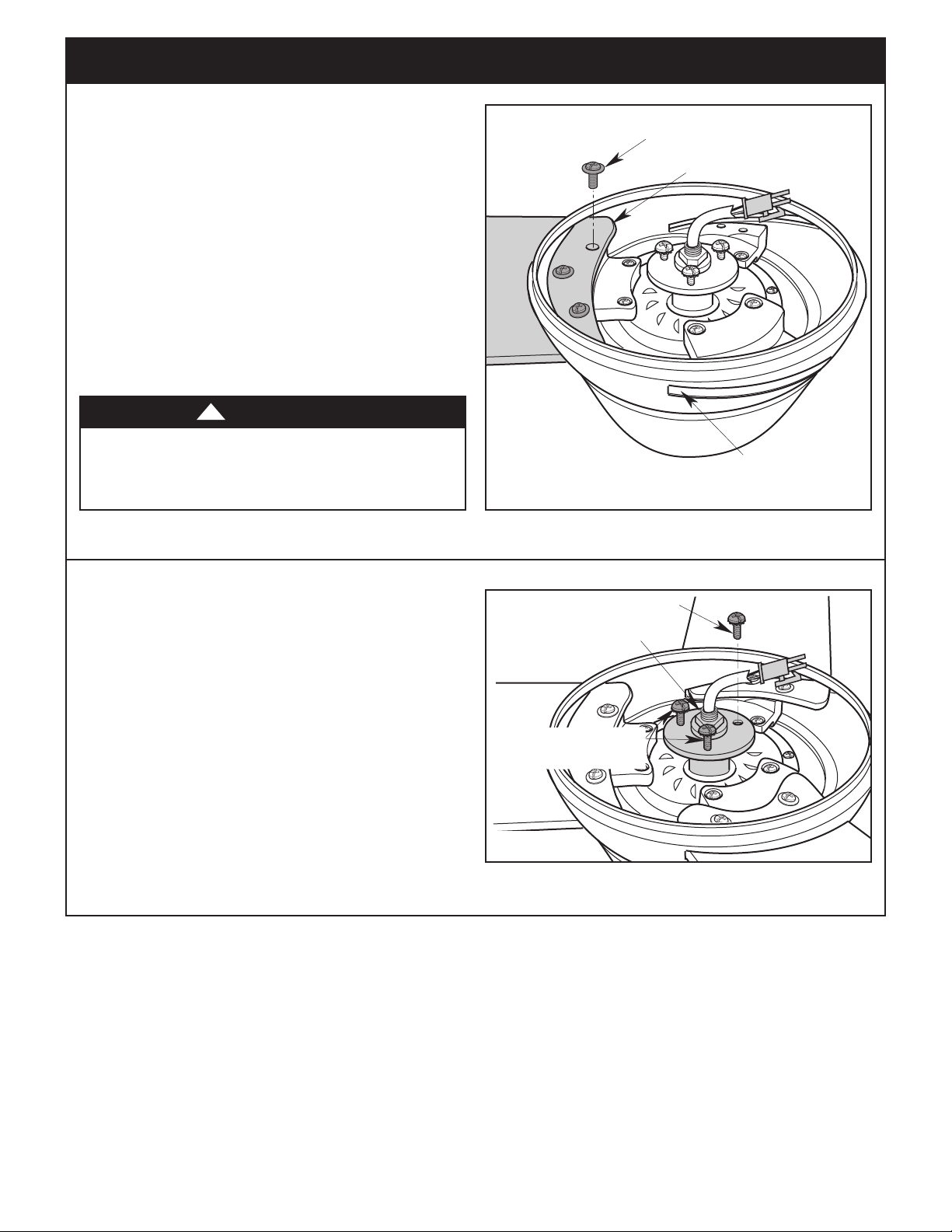
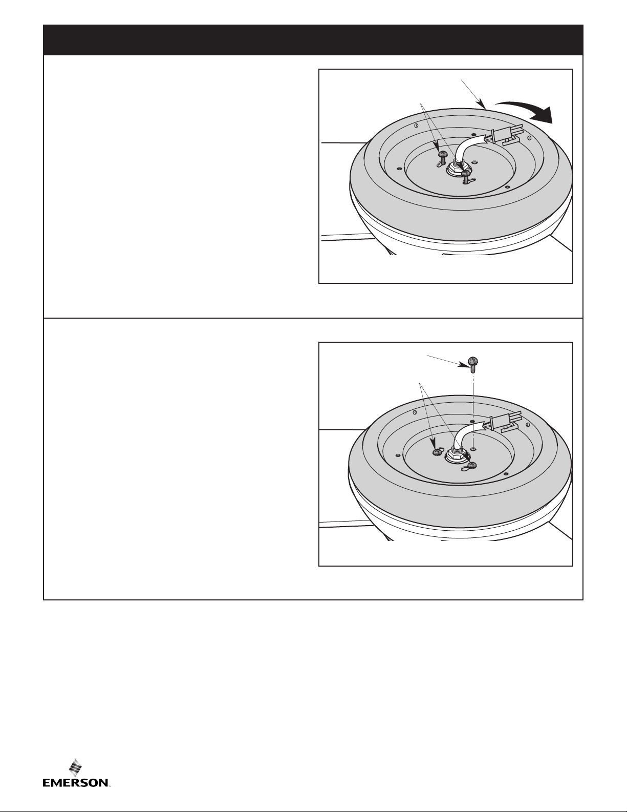
NOTE: The LED Light Fixture Assembly will be
installed during the Final Assembly, after the
Ceiling Fan is Hung and Wired.
Figure 4
ETL Model No.: CF370
6
3. Ceiling Fan Assembly (Continued)
MOTOR
COUPLER
DOWNROD
LOOSEN SET
SCREWS (2)
3.5
Carefully turn the partially assembled Ceiling Fan right
side up and place the Fan securely into the packing
styrofoam. Careful not to bend the Blades.
Remove the Hanger Ball by loosening the Phillips Head
Set Screw in the Hanger Ball until the Ball falls freely
down the 4.5” Downrod (Figure 5).
Remove the Pin from the 4.5” Downrod, then remove
the Hanger Ball (Figure 5).
Retain the Pin and Hanger Ball for reinstallation in
Step 3.12.
Note: Do not loosen the Screw that attaches the
Green Ground Wire to the Hanger Ball.
3.6
Separate, untwist and unkink the Three 80” Motor
Wires.
Route the Three 80” Black, Blue, and White Motor
Wires through the 4.5” Downrod (Figure 6).
Figure 5
GREEN GROUND WIRE
PIN
4.5" DOWNROD
HANGER BALL
PHILLIPS HEAD SET SCREW (LOOSENED)
THREE 80" MOTOR
WIRES (UNTWISTED)
3.7
Loosen the Two Phillips Head Set Screws in the Motor
Coupler for installation of the 4.5” Downrod (Figure 7).
Seat the 4.5” Downrod in the Motor Coupler (Figure 7).
Rotate and align the Two Downrod Clevis Pin Holes
with the Two Motor Coupler Clevis Pin Holes (Figure 7).
Figure 7
7
4.5" DOWNROD
Figure 6
emersonfans.com
Please contact 1-800-654-3545 for further assistance
ETL Model No.: CF370
3. Ceiling Fan Assembly (Continued)
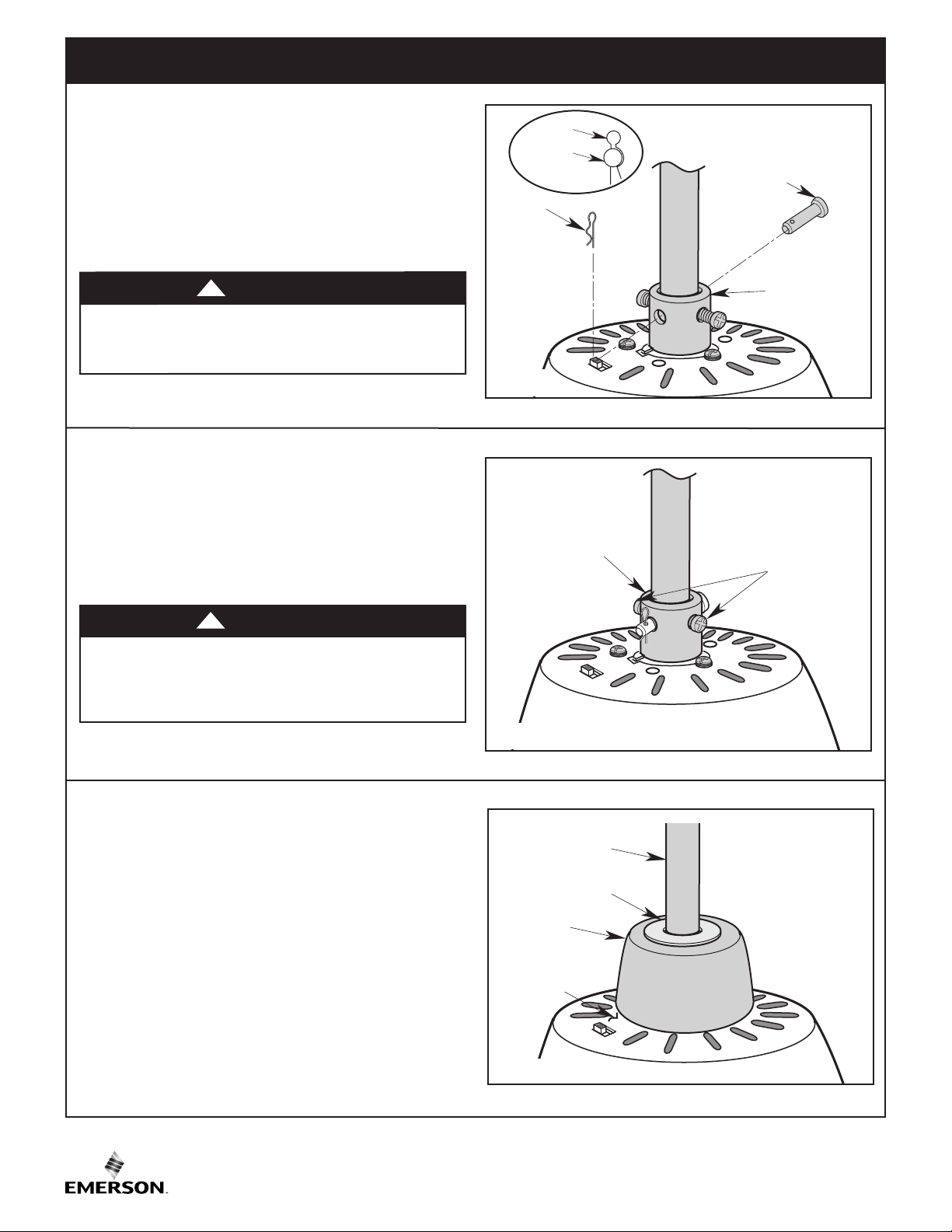
3.8
Install the Clevis Pin and secure with the Hairpin Clip
(Figure 8).
The Clevis Pin must go through the Holes in the Motor
Coupler and Downrod. It is critical that the Clevis Pin
in the Motor Coupler is properly installed and securely
tightened.
!
It is critical that the clevis pin in the motor coupler
is properly installed. Failure to verify that the pin is
properly installed could result in the fan falling.
3.9
While pulling up on the 4.5” Downrod, retighten the Two
Phillips Head Set Screws to secure the 4.5” Downrod in
the Motor Coupler (Figure 9).
NOTE: The Set Screws must be properly installed
as described above, or fan wobble could result.
WARNING
WARNING
!
HAIRPIN
CLIP
CLEVIS
PIN
HAIRPIN
CLIP
Figure 8
MOTOR COUPLER
CLEVIS PIN
MOTOR
COUPLER
RETIGHTEN TWO
PHILLIPS HEAD
SET SCREWS
It is critical that the set screws in the motor coupler are
properly installed and securely tightened. Failure to
verify that the set screws are properly installed could
result in the fan falling.
3.10
Make sure the Grommet is properly installed in the
Coupler Cover, then slide the Coupler Cover on the 4.5”
Downrod until it rests on the Motor Housing (Figure 10).
Figure 9
4.5" DOWNROD
GROMMET
COUPLER
COVER
MOTOR
HOUSING
Figure 10
ETL Model No.: CF370
8
3. Ceiling Fan Assembly (Continued)
3.11
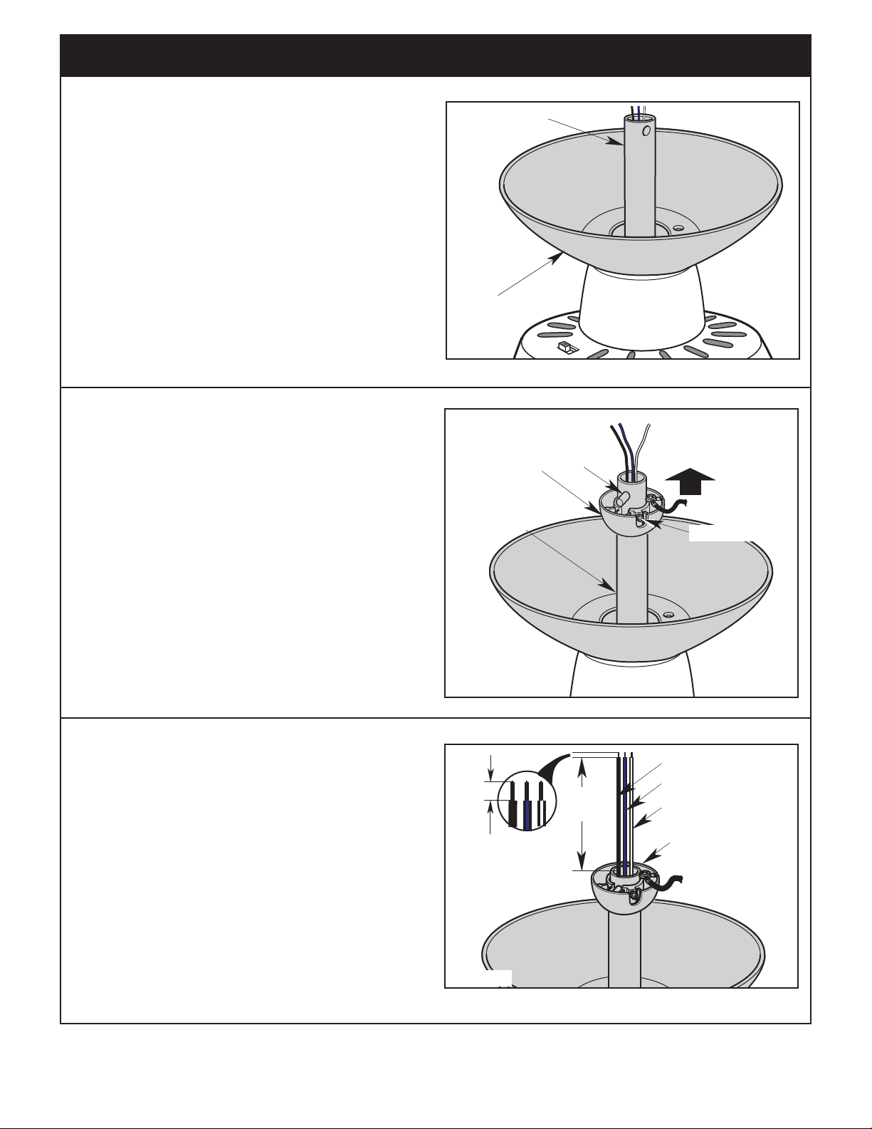
Place the Ceiling Cover over the 4.5” Downrod
(Figure 11).
Be sure that the Ceiling Cover and the Coupler Cover
are both oriented correctly (Figure 11).
3.12
Route the Three Motor Wires through the Hanger Ball
(Figure 12).
Reinstall the Hanger Ball on the 4.5” Downrod as
follows:
Position the Pin through the Two Holes in the 4.5”
Downrod and align the Hanger Ball so the Pin is
captured in the Groove in the top of the Hanger Ball
(Figure 12).
4.5" DOWNROD
CEILING
COVER
Figure 11
HANGER BALL
4.5"
DOWNROD
PIN
SET SCREW
Pull the Hanger Ball up tight against the Pin and
securely retighten the Phillips Head Set Screw in the
Hanger Ball (Figure 12).
A loose Phillips Head Set Screw could create fan
wobble.
3.13
The Fan comes with Black, Blue and White Wires that
are 80-inches long.
Before installing the Fan, measure up approximately
6 to 9-inches above top of Hanger Ball/Downrod
Assembly (Figure 13).
Cut off excess Wires and strip back insulation 1/2-inch
from end of Wires.
Figure 12
1/2
INCH
Figure 13
6 TO 9
INCHES
BLACK WIRE
BLUE WIRE
WHITE WIRE
HANGER
BALL
emersonfans.com
Please contact 1-800-654-3545 for further assistance
9
ETL Model No.: CF370
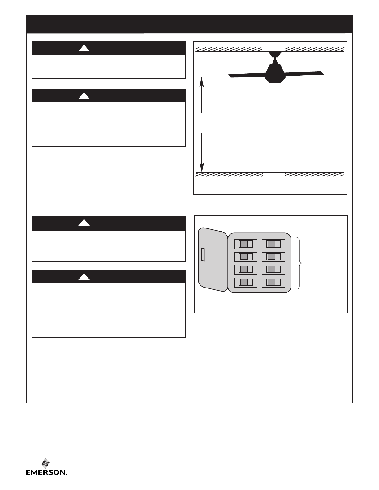
4. How to Hang Your Ceiling Fan
WARNING
The fan must be hung with at least 7’ of clearance from
floor to blades (Figure 14).
WARNING
Turning off wall switch is not sufficient. To avoid
possible electrical shock, be sure electricity is turned
off at the main fuse box before wiring. All wiring
must be in accordance with National and Local codes
and the ceiling fan must be properly grounded as a
precaution against possible electrical shock.
WARNING
!
!
!
CEILING
AT
LEAST
7'
FLOOR
Figure 14
The outlet box and joist must be securely mounted and
capable of supporting at least 50 lbs. Use only a U.L.
outlet box listed as “Acceptable for Fan Support of
22.7 kg. (50 lbs.) or less”.
WARNING
To reduce the risk of fire, electric shock, or personal
injury, mount fan to outlet box marked “Acceptable
for Fan Support of 22.7 kg. (50 lbs.) or less”, and
use screws supplied with outlet box. Most outlet
boxes commonly used for support of light fixtures
are not acceptable for fan support and may need to be
replaced. Consult a qualified electrician if in doubt.
!
4.1
Disconnect Electrical Power to the Branch Circuit at
the Circuit Breaker or Fuse Box before attempting to
install the Ceiling Fan Hanger Bracket on the Outlet Box
(Figure 15).
MAIN FUSE BOX
Figure 15
ETL Model No.: CF370
10
 Loading...