

Emerson CF144GRT00, CF152GRT00, CF152BS00, CF144ORB00, CF152ORB00 Owner's Manual
...
READ AND SAVE THESE INSTRUCTIONS
CONTEMPORARY
CURVA SKY
™
44” & 52” Damp & Wet Location
Snugger Ceiling Fan Owner's Manual
44” Model Numbers
for Damp Locations
CF144BS00
Brushed Steel
44” Model Numbers
for Wet Locations
CF144GRT00
Graphite
CF144ORB00
Oil Rubbed Bronze
52” Model Numbers
for Damp Locations
CF152BS00
Brushed Steel
52” Model Numbers
for Wet Locations
CF152GRT00
Graphite
CF152ORB00
Oil Rubbed Bronze
CF144WW00
Appliance White
Net Weight: 18.5 Lbs.
Questions, problems, missing parts: Before returning to the store call
Part No. F40BP74070004 Form No. BP7407-4
Revision: 170115 U.L. Model No.: CF144 & CF152
CF152WW00
Appliance White
Net Weight: 19.4 Lbs.
Emerson Electric Customer Service
8 a.m. - 6 p.m., Eastern, Monday-Friday
1-800-654-3545
www.emersonfans.com
• Español - página 25
• Français - page 49
Table of Contents
Section Page
Safety Instructions . . . . . . . . . . . . . . . . . . . . . . . . . . . . . . . . . . . . 2
1. Unpacking Instructions . . . . . . . . . . . . . . . . . . . . . . . . . . . . . 3-4
2. Electrical Requirements . . . . . . . . . . . . . . . . . . . . . . . . . . . . . . 4
3. Ceiling Fan Assembly . . . . . . . . . . . . . . . . . . . . . . . . . . . . . .5-6
. How to Hang Your Ceiling Fan . . . . . . . . . . . . . . . . . . . . . . .6-7
4
5. How to Wire Your Ceiling Fan . . . . . . . . . . . . . . . . . . . . . . 8-11
6. How to Assemble Your Light Kit Glass Shade . . . . . . . . . . . 12
7. How to Assemble Your No Light Cover Plate . . . . . . . . . . . . 13
8. Remote Control Procedures . . . . . . . . . . . . . . . . . . . . . . . 14-16
9. Maintenance . . . . . . . . . . . . . . . . . . . . . . . . . . . . . . . . . . . . .17
READ AND SAVE THESE INSTRUCTIONS
Safety Instructions
E
T
O PER
u
urer.
rer.
an
pr
a
lly
e
lo
H
E
n
it
el
an
event
.
Whe
c
k
, to
!
R
I
SK
SON
o
n
ly
If
you
g
o
r clean
d
lo
power
n
t
e
d
,
s
e
th
e service p
OF
S, OB
in
have
ck
he
c
u
F
I
R
E,
SER
a
man
in
g
u
service
fr
om
s
e
rv
ic
re
ly
fa
an
EL
EC
VE T
n
er
quest
n
it, switch
p
an
bei
e
dis
s
t
e
n
el.
T
H
E F
in
ions,
el
ng
c
onne
a
wa
R
ten
d
I
C
OL
p
isco
swi
c
rn
A
L
L
d
ed
cont
o
wer o
tched
t
ing
in
SH
OWIN
b
ac
n
n
ectin
m
g
d
e
OC
y
t
e
G:
th
t
ff at
a
v
ic
K
e
he
g
on
ns
e
WARNING
T
O
R
ED
U
IN
JU
R
U
se
th
m
anuf
man
u
factu
efo
re servicin
service
means
a
c
c
ide
c
a
n
n
o
su
ch
as a tag
a
nt
t
C
Y T
is
ct
p
to
b
OR
a.
b
.
B
1. Read your owner’s manual carefully and keep it for future
reference.
2. Be careful of the fan and blades when cleaning, painting,
or working near the fan. Always turn off the power to the
ceiling fan before servicing.
3. Do not put anything into the fan blades while they are
turning.
4. Do not operate reversing switch until fan blades have
come to a complete stop.
Additional Safety Instructions for Installation
1. To avoid possible shock, be sure electricity is turned off
at the fuse box before wiring, and do not operate fan
without blades.
2. All wiring must be in accordance with the National
Electrical Code “ANSI/NFPA 70-2014” and Local
Electrical Codes. Use the National Electrical Code if
Local Codes do not exist. The ceiling fan must be
grounded as a precaution against possible electrical
shock. Electrical installation should be made or
approved by a licensed electrician.
Section Page
10. Accessories . . . . . . . . . . . . . . . . . . . . . . . . . . . . . . . . . . . . . 17
11. Light Kit Circuit Breaker . . . . . . . . . . . . . . . . . . . . . . . . . . . 17
12. Troubleshooting . . . . . . . . . . . . . . . . . . . . . . . . . . . . . . . . . . 18
13. Remote Control Troubleshooting . . . . . . . . . . . . . . . . . . . . 19
4. Energy Efficient Use of Ceiling Fans . . . . . . . . . . . . . . . . . . 19
1
15. Repair Parts . . . . . . . . . . . . . . . . . . . . . . . . . . . . . . . . . . 20-21
Ceiling Fan Limited Warranty . . . . . . . . . . . . . . . . . . . . . . . . . . .23
Spanish . . . . . . . . . . . . . . . . . . . . . . . . . . . . . . . . . . . . . . . . . . . . 25
French . . . . . . . . . . . . . . . . . . . . . . . . . . . . . . . . . . . . . . . . . . . . .49
3. The outlet box and joist must be securely mounted and
capable of reliably supporting at least 50 pounds. Use
,
,
only U.L. outlet boxes listed as “Acceptable for Fan
Support of 22.7 kg. (50 lbs.) or less”, and use the
mounting screws provided with the outlet box. Most
outlet boxes commonly used for support of light fixtures
are not acceptable for fan support and may need to be
replaced. Consult a qualified electrician if in doubt.
4. The downrod furnished with the fan provides the
minimum recommended floor to fan blade clearance for
an 8 foot ceiling.
5. The fan must be mounted with the fan blades at least
7 feet from the floor to prevent accidental contact with
the fan blades.
6. Follow the recommended instructions for the proper
method of wiring your ceiling fan. If you do not know
enough about electrical wiring, have your fan installed by
a licensed electrician.
NOTE: This fan is suitable for use with solid-state speed
controls.
NOTE: All setscrews must be checked and re-tightened
where necessary before installation.
WARNING
To reduce the risk of electrical shock, this fan must be
installed with an isolating wall control/switch.
To reduce the risk of fire or electrical shock, this fan
should only be used with fan speed control, Model No.
UC8013R, manufactured by Rhine Electric Co., Ltd.
To avoid fire, shock or injury, do not use an Emerson or
any other brand of control not specifically approved for
this fan.
This product is designed to use only those parts supplied
with this product and/or any accessories designated
specifically for use this product by Emerson Electric Co.
Substitution of parts or accessories not designated for
use with this product by Emerson could result in
personal injury or property damage.
To reduce the risk of personal injury, do not bend the
blade flange when installing the blade flanges, balancing
the blades or cleaning the fan. Do not insert foreign
objects in between rotating fan blades.
!
U.L. Model No.: CF144 & CF152
2
1. Unpacking Instructions
C
A
B
D
K
J
I
H
G
F
E
4
5
2
1
3
PROTECTIVE
PLASTIC BAG
Do
m
i
T
h
w
i
sp
C
o
fo
r
resu
1.1
O
p
e
unit.
re
ce
N
O
T
e
x
p
N
O
T
s
m
a
p
ar
c
a
ta
n
o
ssi
n
i
s
p
t
h
t
eci
fi
.
S
u
u
se
l
t
n
ca
Rem
i
ve
E:
l
o
d
E: Pl
ll
c
ts ar
l
o
g
t
g
.
r
o
d
hi
s
cal
b
sti
w
i
n
rt
d
t
I
f
e
d
onta
o
i
n
s
t
C
al
u
ct
pr
l
y
fo
tu
i
th
p
er
so
o
n
ov
h
e
f
y
o
u
v
i
e
a
c
e
ine
e mi
u
tl
e
a
l
l
o
r
l
T
o
l
l
-F
1-
i
s
d
esi
oduc
t
r
u
se
ti
o
n
o
th
i
s
p
n
al
i
co
n
t
a
i
e parts
o
ll
o
w
in
a
r
e
u
w
i
l
l
u
th
e
p
r
to
ssi
n
t
fo
r
r
!
WA
u
s
e
r
ee:
800-
!
WA
g
n
ed
a
nd/
w
i
th
f
p
arts
ro
d
u
ct
n
j
u
r
y
n
i
n
g
f
and
g
p
a
n
c
e
r
s
tr
a
ti
a
r
ts
fr
k
e
e
g
,
co
e
p
l
a
c
f
a
n
654-
to
u
or
a
th
i
s
o
r
b
y
o
r
p
ro
a
n
.
R
c
rt
s:
ta
i
n
o
n
.
o
m
p the
n
tact yo
e
m
e
R
N
i
f
a
n
R
N
se
o
n
ny
a
c
p
r
o
d
u
accesso
E
m
erso
p
er
ty
e
mo
hec
k
o
f
p
a
th
e
m
fr
n
t
b
IN
G
y
p
a
rt
3545
IN
G
l
y
th
o
c
e
s
s
or
ct
b
y
ri
es
n
E
d
am
ve
t
o
p
to
s
ee that
r
t
d
e
s
l
o
o
s
e
om
be
u
r
l
o
e
fo
r
e
p
se
E
l
ag
c
p
i
s
p
i
e
m
n
ectr
e.
h
a
r
i
a
ing
cal
r
o
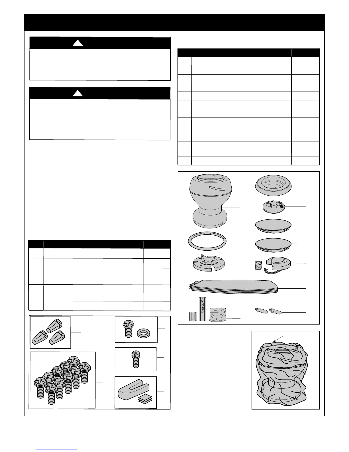
PACKAGE CONTENTS
d
a
ma
g
e
d
ar
ts
su
p
p
l
i
n
y
n
s
st
i
E
o
ou
,
a
t.
i
n
gna
l
ectri
g
n
.
co
yro
r
e
g
l
g
ated
f
hav
fe
s
i
If
er
.
ed
t
e
u
o
r
n
a
s
de
er
so
o
t
d
esi
i
c
C
l
f
o
f
p
ti
o
r
ts
b
los
r
etai
c
e
e
d
Part Description Quantity
o
r
A Fan Motor Assembly 1
B Ceiling Trim Ring 1
C Ceiling Mounting Plate 1
D Fan Blades 3
E Lower Housing 1
F Light Kit Plate 1
d
G Glass Shade 1
c
H No-Light Cover Plate 1
l
d
I 6-Speed Electronic Receiver Control
with Parts Bag 1
J 6-Speed Handheld Transmitter
with Wall Bracket 1
K 50-Watt Halogen Mini Candelabra Bulbs 2
a
m
e
to
a
ny
o
r
HARDW
Part
1
W
ir
2
M5
3
M5
Sc
4
M4
L
5
Blade Balance Kit
ARE
e
C
x
1
x
1
r
e
x
1
o
w
e
6
0
w
0
o
n
mm
mm
mm
r
n
w
H
CONT
D
escri
e
c
t
o
r
s
,
Fla
n
g
Pa
n
H
it
h
W
a
s
Pa
n
H
o
u
s
in
g
a
E
NT
S
pt
i
on
Q
uant
i
t
y
1
2
g
a
.
3
e
H
e
a
d
Bla
d
e
Sc
r
e
w
s
1
0
e
a
d
C
e
ilin
g
C
o
v
e
r
h
e
r
(
s
p
a
r
e
)
1
e
a
d
Sc
re
w
f
o
r
n
d
L
ig
h
t
Kit
(s
p
a
r
e
)
1
1
1.2
Re move the fan motor
as sembly fr om the
protective plastic bag.
Place all carton contents on
a protective surface.
emersonfans.com
3
Please contact 1-800-654-3545 for further assistance
U.L. Model No.: CF144 & CF152
1. Unpacking Instructions (Continued)
THE FAN MODELS CF144BS & CF152BS ARE SUITABLE FOR
DAMP LOCATIONS SUCH AS COVERED PORCHES, COVERED PATIOS,
AND COVERED DECKS...ANYWHERE THERE IS A ROOF OVERHEAD.
THE FAN MODELS CF144GRT, CF144ORB, CF144WW, CF152GRT, CF152ORB,
& CF152WW ARE SUITABLE FOR WET LOCATIONS
SUCH AS PORCHES, PATIOS, AND DECKS.
This Manual Is Designed to Make it as Easy as Possible for You to Assemble,
Install, Operate and Maintain Your Ceiling Fan
Tools Needed for Assembly
One Phillips head screwdriver One stepladder
One wire stripper One wire cutter
Materials
Wiring outlet box and box connectors must be of type
required by the local code. The minimum wire would be a
3-conductor (2-wire with ground) of following size:
Installed Wire Length Wire Size A.W.G.
Up to 50 ft. 14
50-100 ft. 12
2. Electrical Requirements
IMPORTANT: Your ceiling fan will not function
properly, and may be damaged, if used with any wall
dimmer switch or control other than the Emerson
Electric Fan/Light Remote Control supplied with the
fan.
Your new ceiling fan will require a grounded electrical
supply line of 120 volts AC, 60 Hz, 15 amp circuit.
The outlet box must be securely anchored and capable of
withstanding a load of at least 50 pounds.
Your Emerson ceiling fan comes supplied with a Fan/Light
Remote Control which consists of a receiver mounted
inside the ceiling cover of the fan motor housing. This
system allows you to regulate your ceiling fan speed and
light ON/OFF.
WARNING
Before assembling your ceiling fan, refer to section on
proper method of wiring your fan (page 8). If you feel you
do not have enough wiring knowledge or experience,
have your fan installed by a licensed electrician.
If your fan is to replace an existing ceiling light fixture, turn
electricity off at the main fuse box at this time and remove
the existing light fixture.
WARNING
Turning off wall switch is not sufficient. To avoid possible
electrical shock, be sure electricity is turned off at the
main fuse box before wiring. All wiring must be in
accordance with National and Local codes and the ceiling
fan must be properly grounded as a precaution against
possible electrical shock.
!
!
WARNING
To reduce the risk of fire, electric shock, or personal
injury, mount fan to outlet box marked “Acceptable for
Fan Support of 22.7 kg. (50 lbs.) or less”, and use screws
supplied with outlet box. Most outlet boxes commonly
used for support of light fixtures are not acceptable for
fan support and may need to be replaced. Consult a
qualified electrician if in doubt.
U.L. Model No.: CF144 & CF152
!
WARNING
To avoid fire or shock, follow all wiring instructions
carefully.
Any electrical work not described in these
instructions should be done or approved by a licensed
electrician.
Pl ease ca ll Emer son tec hnical support at
1- 800-654- 3545 i f you have any questi ons ab out
installation and operation of this ceiling fan.
4
!
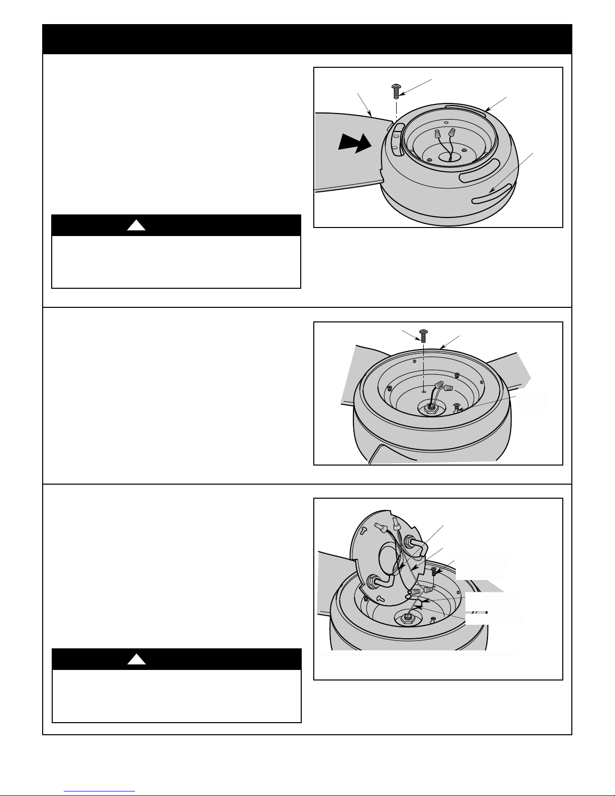
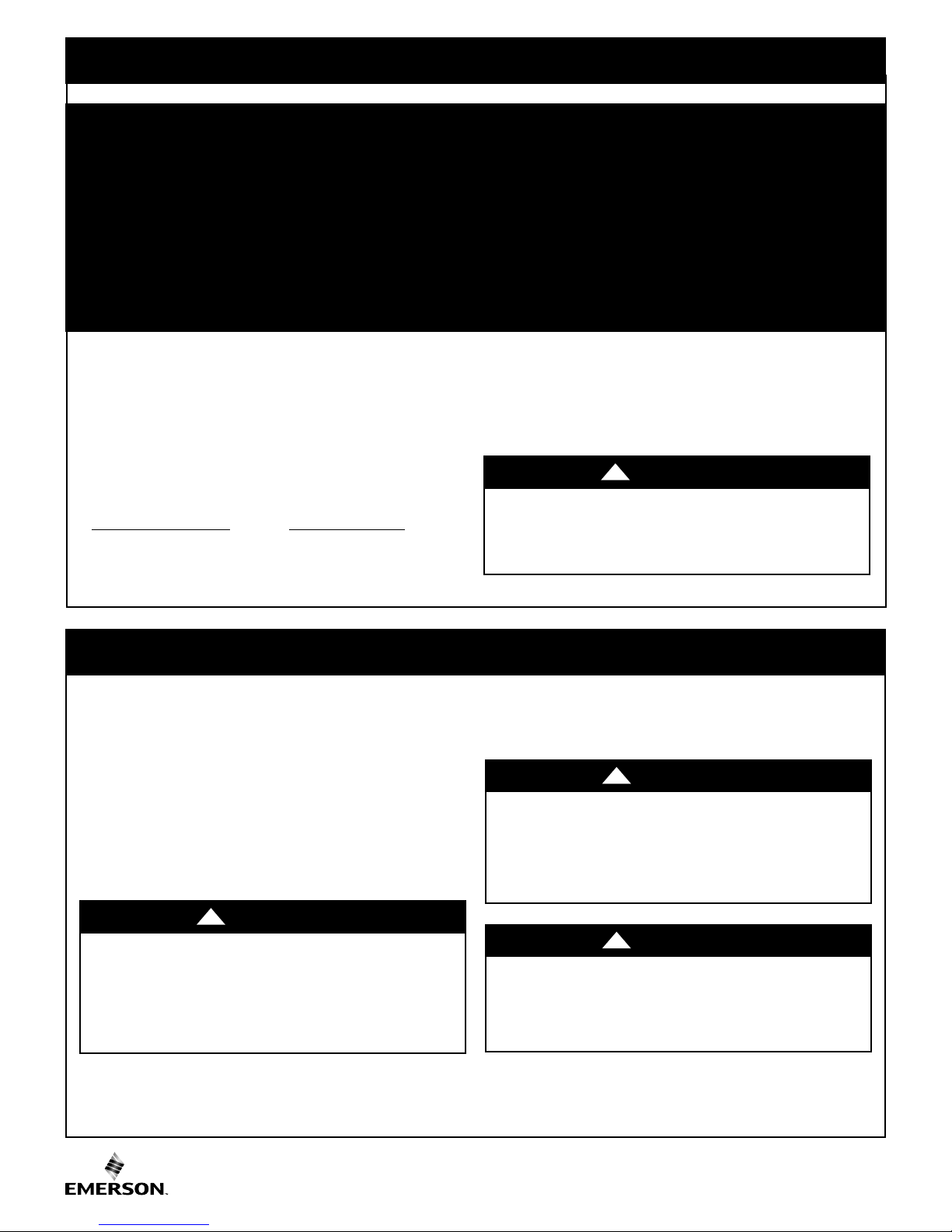
3. Ceiling Fan Assembly
M5 x 16mm FLANGE HEAD
BLADE SCREWS (3 per blade)
SLIDE FAN BLADE
INTO BLADE
CENTER SLOT
F
AN BLADE
BLADE
SLOT
FAN HOUSING
REMOVE M4 x 10mm
PAN HEAD SCREW
LOWER HOUSING
KEY HOLE
SLOT (2)
LIGHT KIT BLACK WIRE
LIGHT KIT WHITE WIRE
FAN MOTOR BLUE
WIRE
REMOVE ONE M4 x 10 mm
PAN HEAD LOWER
HOUSING SCREW
FAN MOTOR WHITE WIRE
1
3.
w
o
d
e
d
si
p
u
y
l
b
m
ss e
a
r
o
t
o
m
n
a
f
e
h
t
n
o
i
t
si
o
P
.
s
e
d
a
l
b
n
fa
e
re
th
e
th
g
n
ti
n
u
r mo
fo
n
o
ti
ra
a
p
re
p
em
s
s
a
g
n
i
us
o
h
n
a
f
n
i
t
o
l
s
de
a
l
b
ugh
o
r
h
t
de
a
l
b
de
i
l
S
fl
mm
6
1
x
M5
e
re
th
g
n
i
s
u
g
n
i
s
u
o
h
n
fa
to
e
d
a
l
b
t
n
u
Mo
).
1
re
u
g
i
(F
s
w
re
c
s
e
d
a
l
b
d
a
e
h
e
s
s
a
g
in
s
u
o
h
n
fa
h
tc
a
r
c
s
t to
o
n
e
r
a
c
e
k
a
E: T
OT
N
.
s
e
d
la
b
g
llin
ta
s
in
n
e
wh
per
ion
allat
t
ins
blades
wo
!
sse
y sl
o
u
o
a
p
re
se
si
mb
o
n
t w
a
e
t h
n
n
t
M4
e
a
g
a
h
y a
l
as
l
o
scre
d
sse
s p
a
e
x 1
n
s
s o
e
re
d
0
l
d
em
f th
w
mb
o
vi
scre
n
a
mm p
th
n
se
o
o
he
t
o
t
bly
w
o
l
e
re
u
g
s (Fi
g
y ti
y b
l
mo
y re
sl
u
supplied in par
w
scre
d
a
e
h
n
i
n
i
ma
re
e
ot
m
an
f
g
n
si
u
o
r h
e
).
2
th
g
n
i
n
te
h
.
d
ve
s bag,
t
aining
em
r
he
t
e
plet
Com
.
s
n
o
ti
c
tru
s
n
i
e
v
o
b
a
WARNING
To reduce the risk of personal injury, do not bend the
blade flange when installing the blade flanges,
balancing the blades or cleaning the fan. Do not insert
foreign objects in between rotating fan blades.
3.2
th
e
f th
o
e
n
o
ve
mo
e
R
a
g
n
si
u
o
r h
to
mo
e
th
).
2
re
u
g
s (Fi
w
scre
housing
lower
he
t
h
ac
t
At
ke
o
tw
e
th
g
n
i
n
g
i
l
a
o
l
g
n
si
u
o
r h
to
mo
e
th
r h
e
w
o
l
e
th
re
cu
e
S
s.
w
scre
th
w
scre
e
th
l
l
sta
n
i
e
R
mm
0
x 1
e M4
A spar
needed.
if
e
m
g
or
a
w
o
n
b
n
s i
tw
tw
n
i
.
y
l
e
g
ly
b
he
t
Figure 1
n
o
by
to
n
o
Figure 2
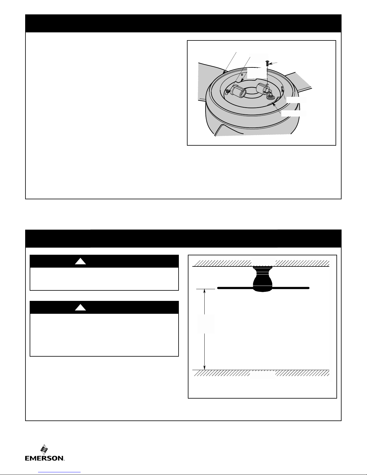
3.3
cto
e
n
n
co
re
i
w
e
th
n
i
ta
re
d
n
a
ve
mo
e
R
s.
re
i
w
e
u
l
b
ire from the ceiling fan to the white
onnect the w
C
wire of the light k
from the
Use wire co
connec
Remov
tions
e one of the three M4 x
the lower housing and loosen the remaining two screws
(Figure 3).
WARNING
To avoid possible fire or shock, the connectors should
not be removed unless immediately installing the light kit.
Power should be turned off prior to connector removal
and light kit installation.
hite w
it plate (Figure 3). Connect the blue wire
wire of
eiling fan
c
the blac
to
k
nnectors (previously removed) to make
.
10 mm pan head screws in
!
fro
rs
e
th
m
light kit plate.
the
d
n
a
te
i
h
w
Figure 3
emersonfans.com
Please contact 1-800-654-3545 for further assistance
5
U.L. Model No.: CF144 & CF152
3. Ceiling Fan Assembly (Continued)
M4 x 10mm PAN HEAD
S
CREW
KEY HOLE SLOT (2)
L
OWER HOUSING
LIGHT KIT PLATE
DIMPLES
CUT OUT
NOTCHES
CEILING
FLOOR
AT
LEAST
7'
3.4
uck the wires and connectors into the fan housing.
T
Position the light kit plate into the fan housing by placing
the cut out notches over the fa n hou sing dimple s
(Figure 4).
OTE: Make sure all wires and connectors are tucked
N
under the light kit plate and not pinched between light
kit plate and fan housing.
Attach the light kit plate assembly to the lower housing by
aligning the two key slot holes of the light kit plate onto the
lower housing loosened screws (Figure 4).
Secure the light kit plate assembly by tightening the two
screws.
Reinstall the M4 x 10 mm pan head screw that was
previously removed.
A spare M4 x 10 mm pan head screw supplied in parts bag,
if needed.
Figure 4
4. How to Hang Your Ceiling Fan
WARNING
The fan must be hung with at least 7' of clearance from
floor to blades (Figure 5).
WARNING
Turning off wall switch is not sufficient. To avoid possible
electrical shock, be sure electricity is turned off at the
main fuse box before wiring. All wiring must be in
accordance with National and Local codes and the ceiling
fan must be properly grounded as a precaution against
possible electrical shock.
!
!
Figure 5
U.L. Model No.: CF144 & CF152
6
OUTLET BOX SCREWS (2)
CEILING MOUNTING
PLATE HOOK
CEILING MOUNTING
PLATE
OUTLET BOX
4.
CEILING
TRIM RING
FAN MOTOR
ASSEMBLY
FAN MOTOR
ASSEMBLY
HOOK
CEILING
MOUNTING PLATE
How
to
Hang
Your
Cei
ng
i
l
Fan
)
ed
u
in
t
n
o
C
(
WARNING
The outlet box and joist must be securely mounted and
capable of supporting at least 50 lbs. Use only a U.L.
outlet box listed as “Acceptable for Fan Support of
22.7 kg. (50 lbs.) or less”.
WARNING
To reduce the risk of fire, electric shock, or personal
injury, mount fan to outlet box marked “Acceptable for
an Support of 22.7 kg. (50 lbs.) or less”, and use screws
F
supplied with outlet box. Most outlet boxes commonly
used for support of light fixtures are not acceptable for
fan support and may need to be replaced. Consult a
qualified electrician if in doubt.
!
!
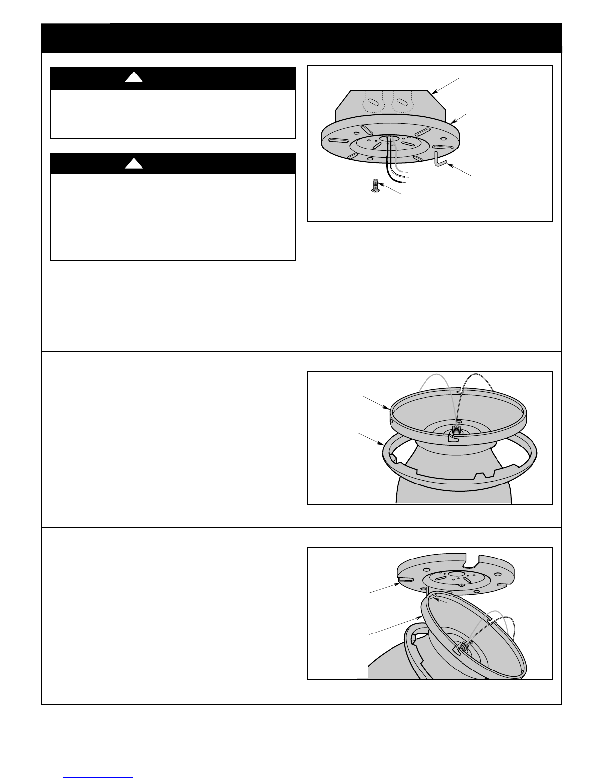
4.1
Disconnect electrical power to the branch circuit at the
circuit breaker or fuse box before attempting to install the
ceiling fan mounting plate on the outlet box.
Figure 6
4.2
Pull the electrical supply black, white and ground wires
through the center opening of the ceiling mounting plate
before securing the plate to the outlet box (Figure 6).
Position the ceiling mounting plate onto the outlet box and
secure using the two outlet box screws, supplied with
outlet box (Figure 6).
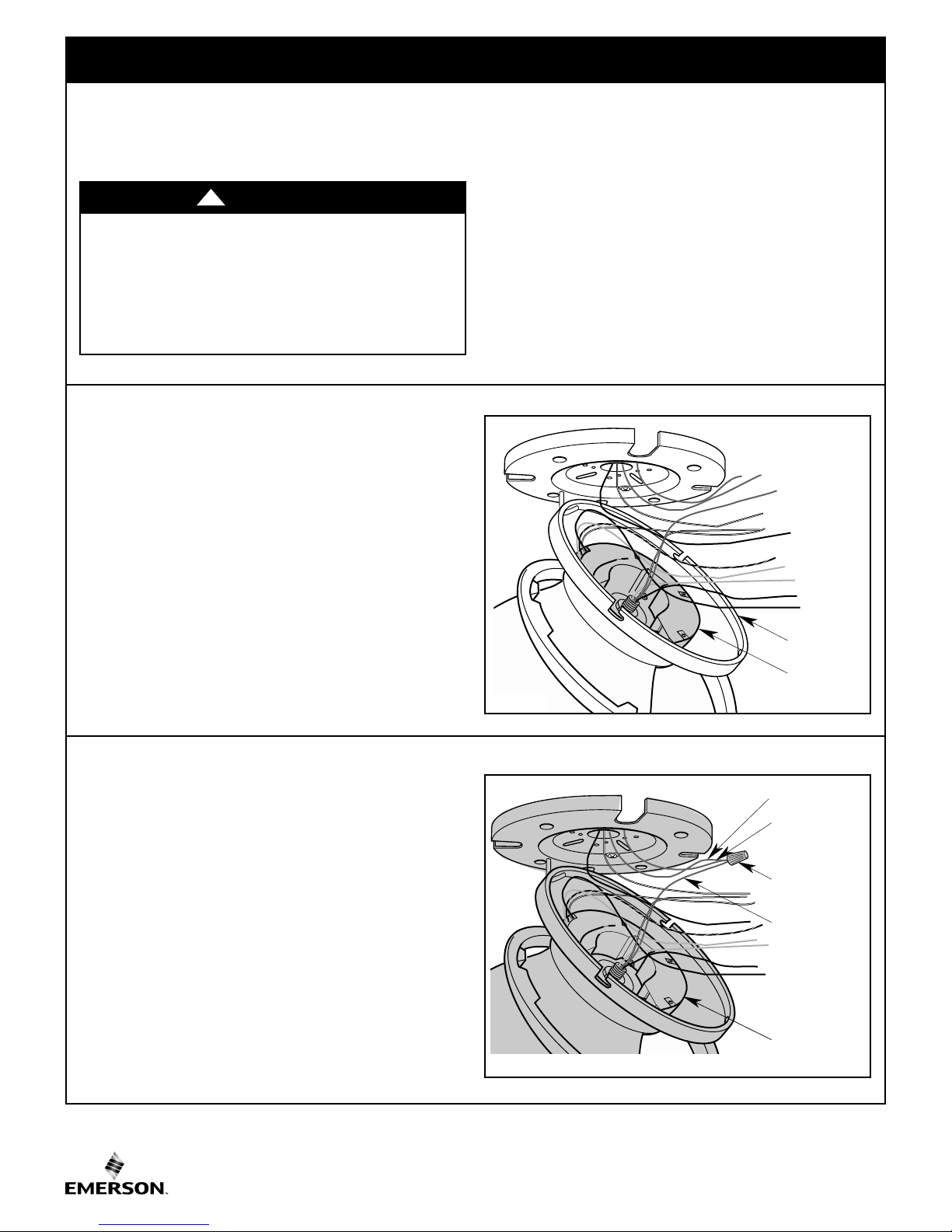
4.3
Slide the ceiling trim ring over the fan motor assembly and
let it rest on the motor assembly (Figure 7).
4.4
Place the motor assembly onto the ceiling mounting plate
hook during wiring fan motor assembly to outlet box
(Figure 8).
Figure 7
Figure 8
emersonfans.com
Please contact 1-800-654-3545 for further assistance
7
U.L. Model No.: CF144 & CF152
5. How to Wire Your Ceiling Fan
RECEIVER
FAN MOTOR
HOUSING
RECEIVER
SUPPLY GREEN
WIRE
FAN ASSEMBLY
GREEN WIRE
WIRE
CONNECTOR
CEILING
MOUNTING
PLATE GREEN
WIRE
If you feel that you do not have enough electrical
wiring knowledge or experience, have your fan
installed by a licensed electrician.
WARNING
Turning off wall switch is not sufficient. To avoid
possible electrical shock, be sure electricity is
turned off at the main fuse box before wiring. All
wiring must be in accordance with National and
Local codes and the ceiling fan must be properly
grounded as a precaution against possible
electrical shock.
!
5.1
Position the receiver into the fan motor housing as shown
in Figure 9.
Refer to Figures 9 and 15 to connect the receiver wires to
the supply wires and the fan motor wires using the wire
connectors supplied with the fan as follows:
CAUTION: To reduce the risk of electrical shock,
disconnect the electrical supply circuit before
installing the fan, light kit or receiver.
NOTE: Make all wiring connections using wire
connectors (supplied). Make sure that all connections
are tight, including ground, and that no bare wire is
visible at the wire connectors, except for the ground
wire.
5.2
Securely connect the ceiling mounting plate green wire
and the supply green grounding wire (this may be a bare
wire or a wire with green insulation) to the fan assembly
green wire using a wire connector (Figure 10).
Figure 9
Figure 10
U.L. Model No.: CF144 & CF152
8
 Loading...