

Page 1
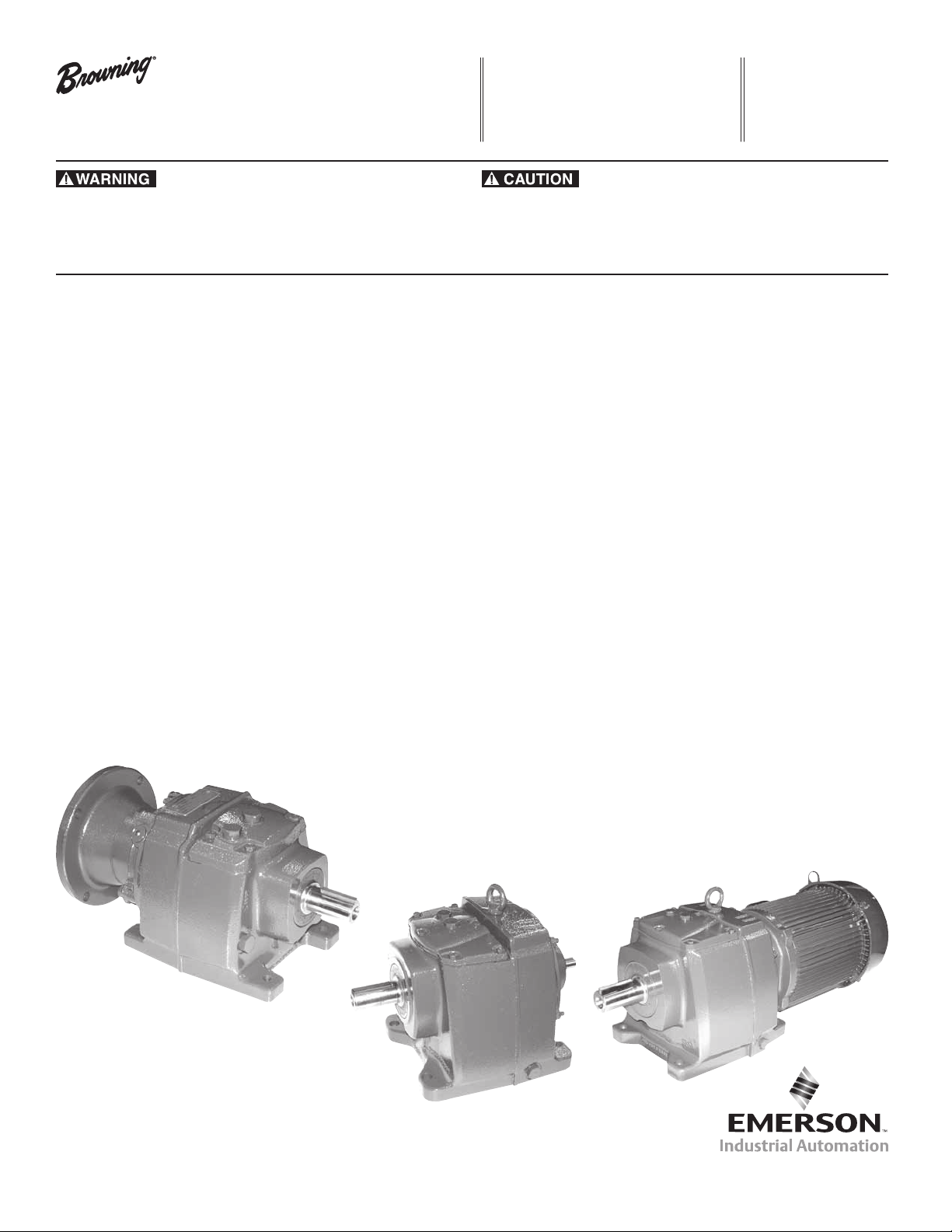
Installation and Maintenance Manual
CbN Series 3000
Gearmotors and Reducers
Emerson Industrial Automation
7120 New Bufngton Road
Florence, KY 41042
Application Engineering: 800 626 2093
www.emerson-ept.com
F O R M
8772E
Revised
May 2012
• Read and follow all instructions carefully.
• Disconnect and lock-out power before installation and maintenance.
Working on or near energized equipment can result in severe injury or death.
• Do not operate equipment without guards in place. Exposed equipment can
result in severe injury or death.
Safety First
High voltage and rotating parts can cause serious or fatal injury. Safe installation,
operation and maintenance must be performed by qualied personnel. Familiarization with and adherence to NEMA MG2, the National Electric Code and local codes
is recommended. It is important to observe safety precautions to protect personnel
from possible injury. Personnel should be instructed to:
1. Avoid contact with energized circuits or rotating parts.
2. Disconnect all power sources before initiating any maintenance or repair.
3. Act with care in accordance with prescribed procedures in handling and
lifting this equipment.
4. Be sure the unit is electrically grounded in accordance with code
requirements.
5. Be sure equipment is properly enclosed to prevent access by children
or other unauthorized personnel in order to prevent possible accidents.
6. Be sure shaft key is fully captive before unit is energized.
7. Avoid contact with capacitors until safe discharge procedures have
been completed.
8. Most units are shipped with oil. Always be sure oil lubricated units are
lled with correct oil to proper level before operating.
9. Provide proper safeguards for personnel against rotating parts and
applications involving high inertia loads, which can cause overspeed.
10. Avoid extended exposure to equipment with high noise levels.
11. Be familiar with the equipment and read all instructions thoroughly
before installing or working on equipment.
• Periodic inspections should be performed. Failure to perform proper maintenance
can result in premature product failure and personal injury.
Installation Instructions
Start-Up
Before operating the reducer or gearmotor, the following must be done:
• Install the drive on a rigid and vibration-free surface.
• Remove the protective coating on the shaft and ange. Use solvent
if necessary.
• Carefully install coupling, sheaves, sprockets, or pinions on shaft.
Mount as close to the shaft shoulder as possible.
• It is preferable to use heat instead of force. Do not hammer on shaft!
• Check shaft alignment when using direct coupling.
• Check shaft parallelism when using belt or chain drive.
CAUTION: Refer to belt manufacturer's recommendation for belt tension.
(Tension should not be applied on chain drives.)
• Check oil level in oil lubricated reducer.
• Install breather plug in the plug hole per recommendations shown on
page (5, 7, or 9) for sizes larger than frame 30.
Maintenance
Safe operation and product performance is improved with periodic inspections. It is
recommended the reducer or gearmotor be inspected every 50 hours of operating
time.
• Check mounting bolts and belt tension (if applicable).
Note: The preventative maintenance list below should be performed every
5000 hours of operating time:
• Check oil level and add oil if necessary.
• Make sure the vent plug pin in the breather is clean.
Browning, Emerson and Emerson Industrial Automation are trademarks of
Emerson Electric Co. or one of its affiliated companies.
©2007, 2010, 2012 Emerson Power Transmission Corp., All Rights Reserved.
MCIM12004E • Form# 8772E • Printed in USA
Page 2
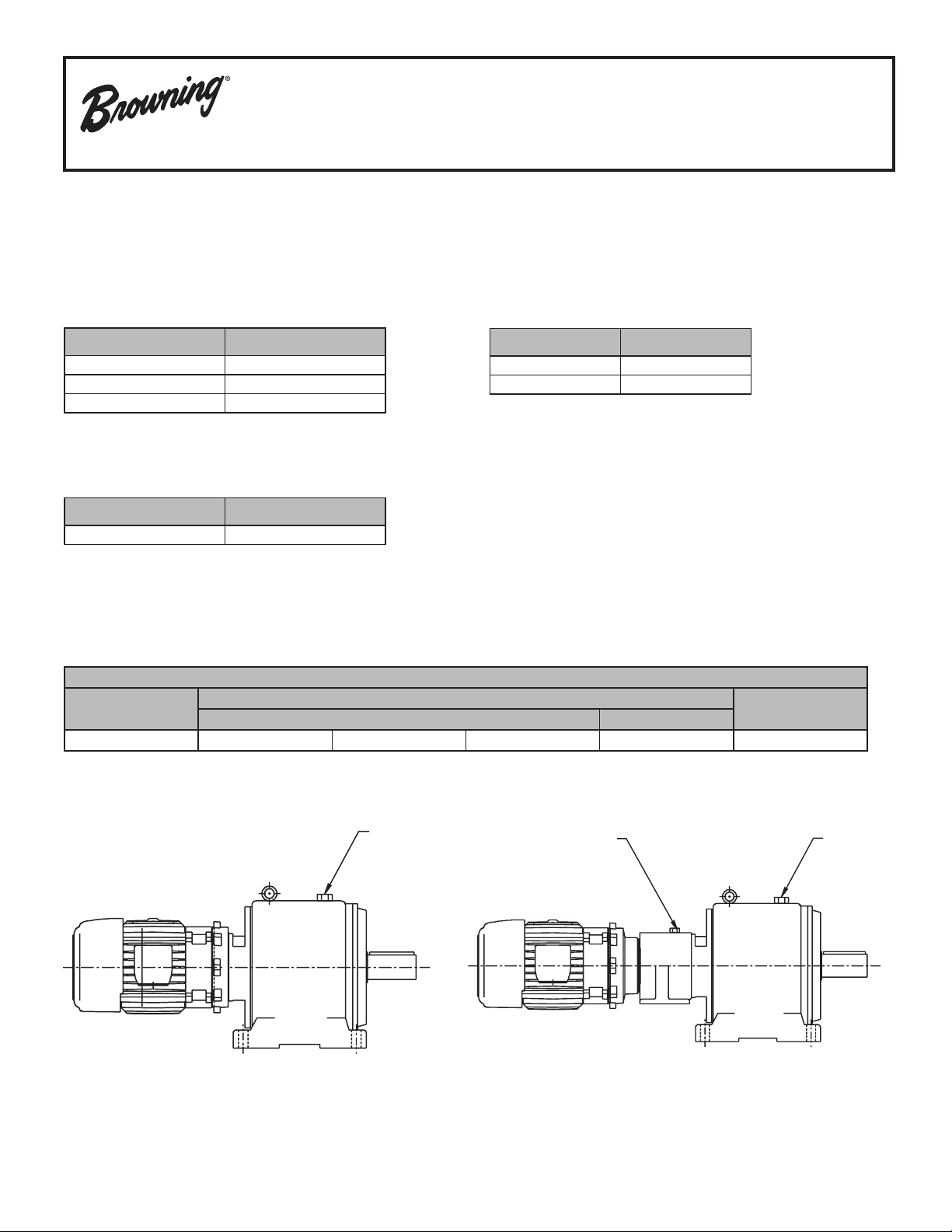
Lubrication
Primary
Series 3000 CbN gearing is shipped with one of the following synthetic lubricants
per the table below and tted with a magnetic drain. Each reducer is lled according
to the mounting position specied when ordered. Refer to the unit nameplate and
the chart to the right for the mounting position arrangement for your unit.
In the case of synthetic oil, the lubricant does not require changing, but it is
recommended that proper oil level be checked periodically.
Standard Synthetic Gear Oil (Non-Food Grade)
No Backstop
Manufacturer
Fuchs * Sintogear 125
Mobil * Mobilgear SHC 150
Shell * Omala Fluids HD 150
-25° F to 125° F
(-30° C to 50° C)
With Backstop (1)
Manufacturer
Shell * Omala RL 100
Mobil * SHC 629
(-30° C to 50° C)
-25° F to 125° F
Standard Synthetic Gear Oil (H1 Rated Food Grade Requirements)
No Backstop
Manufacturer
Mobil * SHC Cibus 150
CAUTION!
• Never mix synthetic oil and mineral oil.
• Never use extreme pressure (EP) oil in a reducer with a backstop.
22° F to 125° F
(-20° C to 50° C)
Acceptable Mineral Oil Lubricants
Ambient Range of Installation
-4°F to 14°F
(-20°C to 10°C)
ISO VG 68 ISO VG 100 ISO VG 150 ISO VG 220 ISO VG 150 ISO VG 320
14°F to 122°F (-10°C to 50°C)
No Backstop With Backstop
122°F and Above
(50°C +)
One Thru Three Stage
Secondary
Combined
Primary
* The following trade names, trademarks and/or registered trademarks are used in this material by Emerson Power Transmission Corporation are NOT owned or controlled by Emerson Power
Transmission Corporation and are believed to be owned by the following parties: Fuchs and Sintogear: Fuchs Corporation, Mobil and Mobilgear. Exxonmobil Oil Corporation; Shell and Omala: Shell
Petroleum Incorporated. Emerson Power Transmission Corporation cannot and does not represent or warrant the accuracy of this information.
2
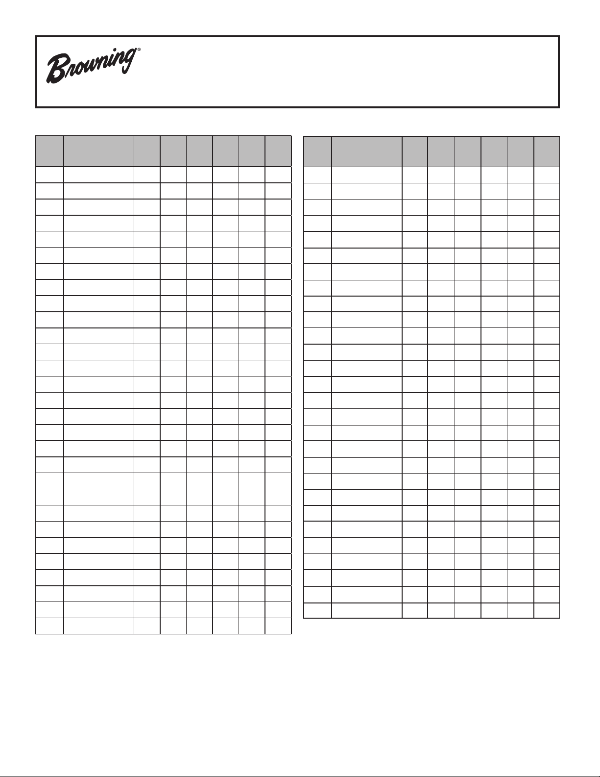
Page 3
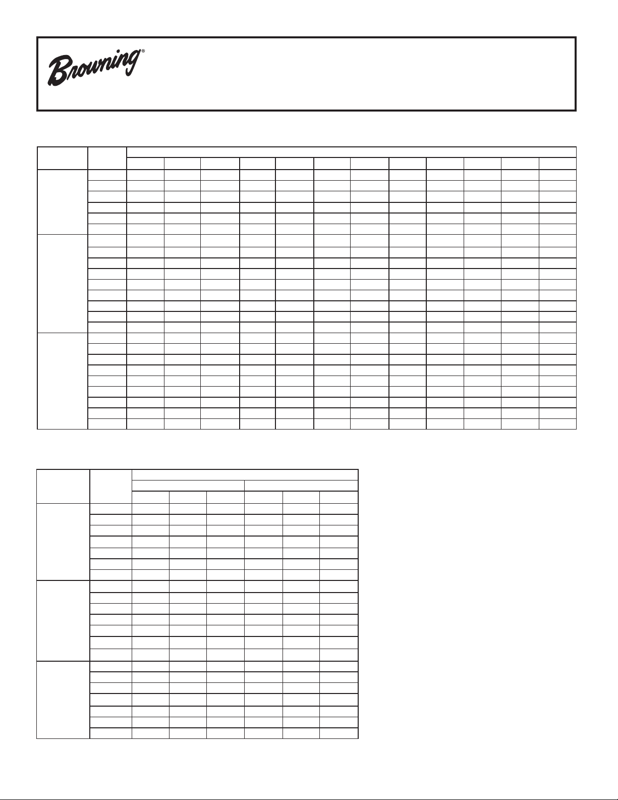
One to Three Reduction
Stages
ONE
TWO
THREE
Gear
Frame
30 0.33 0.33 0.33 0.33 0.33 0.33 0.33 0.33 0.33 0.33 0.33 0.33
31 0.37 0.37 0.53 0.53 0.74 0.53 0.74 0.53 0.58 1.06 0.58 1.06
32 0.26 0.26 0.58 0.58 0.79 0.58 0.79 0.58 0.63 0.84 0.63 0.84
33 0.95 0.95 1.48 1.48 2.01 1.48 2.01 1.48 2.22 2.22 2.22 2.22
34 2.11 2.11 3.17 3.38 4.44 3.17 4.44 3.38 4.02 3.17 4.02 3.17
(single reduction)
(Double Reduction)
(Triple Reduction)
35 3.38 3.38 5.49 5.28 7.71 5.49 7.71 5.28 6.13 5.81 6.13 5.81
30 0.63 0.63 0.63 0.63 0.63 - - - 0.63 0.63 0.63 0.63
31 0.63 0.63 1.00 0.90 1.16 - - - 1.22 1.48 1.22 1.48
32 1.00 1.00 1.85 1.64 2.38 - - - 2.38 2.85 2.38 2.85
33 1.69 1.69 3.49 3.12 4.70 - - - 4.75 4.65 4.75 4.65
34 3.49 3.49 7.40 4.97 7.08 - - - 7.93 7.93 7.93 7.93
35 5.49 5.49 10.46 8.98 13.95 - - - 15.53 14.48 15.53 14.48
36 8.45 8.45 12.69 19.02 23.77 - - - 25.36 25.89 25.36 25.89
37 13.74 13.74 22.19 33.81 40.15 - - - 44.91 43.85 44.91 43.85
38 17.96 17.96 26.42 53.89 61.30 - - - 68.68 64.46 68.68 64.46
30 0.74 0.74 0.74 0.74 0.74 - - - 0.74 0.74 0.74 0.74
31 0.63 0.63 1.30 0.90 1.16 - - - 1.22 1.48 1.22 1.48
32 1.00 1.00 2.43 1.64 2.38 - - - 2.38 2.85 2.38 2.85
33 1.69 1.69 4.62 3.12 4.70 - - - 4.75 4.65 4.75 4.65
34 3.49 3.49 7.40 4.97 7.08 - - - 7.93 7.93 7.93 7.93
35 5.49 5.49 13.21 8.98 13.95 - - - 15.53 14.48 15.53 14.48
36 8.45 8.45 15.85 19.02 23.77 - - - 25.36 25.89 25.36 25.89
37 13.74 13.74 28.50 33.81 40.15 - - - 44.91 43.85 44.91 43.85
38 17.96 17.96 45.44 53.89 61.30 - - - 68.68 64.46 68.68 64.46
B3 B5 B6 B7 B8 B52 B53 B54 V1 V3 V5 V6
Lubrication
Oil Capacities (U.S. Quarts)
Mounting Positions *
* refer to page illustrating mounting positions based on reduction stage(s) and gear frame to be checked or filled
Combined Gear Units -
Composition NOTE:
Stages
FOUR
FIVE
SIX
Combined
Gear Frame
3254 32 Two CbN 30 Two CbN that is factory lled and requires monitoring
3374 33 Two CbN 30 Two CbN before start-up and during operation. The table
3484 34 Two CbN 31 Two CbN at left denes the gear size, and type for each
3594 35 Two CbN 31 Two CbN CbN gear of a specic “combined” gear reducer.
3604 36 Two CbN 32 Two CbN
3734 37 Two CbN 32 Two CbN Refer to the table above for oil volume based
3844 38 Two CbN 34 Two CbN on mounting position specied
3255 32 Two CbN 30 Three CbN
3375 33 Two CbN 30 Three CbN
3485 34 Two CbN 31 Three CbN Oil sumps of frames 36, 37, and 38 are equipped
3595 35 Two CbN 31 Three CbN with a dipstick (with breather) for the
3605 36 Two CbN 32 Three CbN purposes of oil level monitoring when a unit
3735 37 Two CbN 32 Three CbN is not operating.
3845 38 Two CbN 34 Three CbN
3256 32 Three CbN 30 Three CbN
3376 33 Three CbN 30 Three CbN Oil sumps of frames 31 through 35 are equipped
3486 34 Three CbN 31 Three CbN with an oil level plugs for the purposes of
3596 35 Three CbN 31 Three CbN oil level monitoring when that unit is not
3606 36 Three CbN 32 Three CbN operating .
3736 37 Three CbN 32 Three CbN
3846 38 Three CbN 34 Three CbN
Frame Stages Type Frame Stages Type together. Each gear unit has a separate oil sump
Primary Secondary These consist of 2 CbN gear units assembled
3
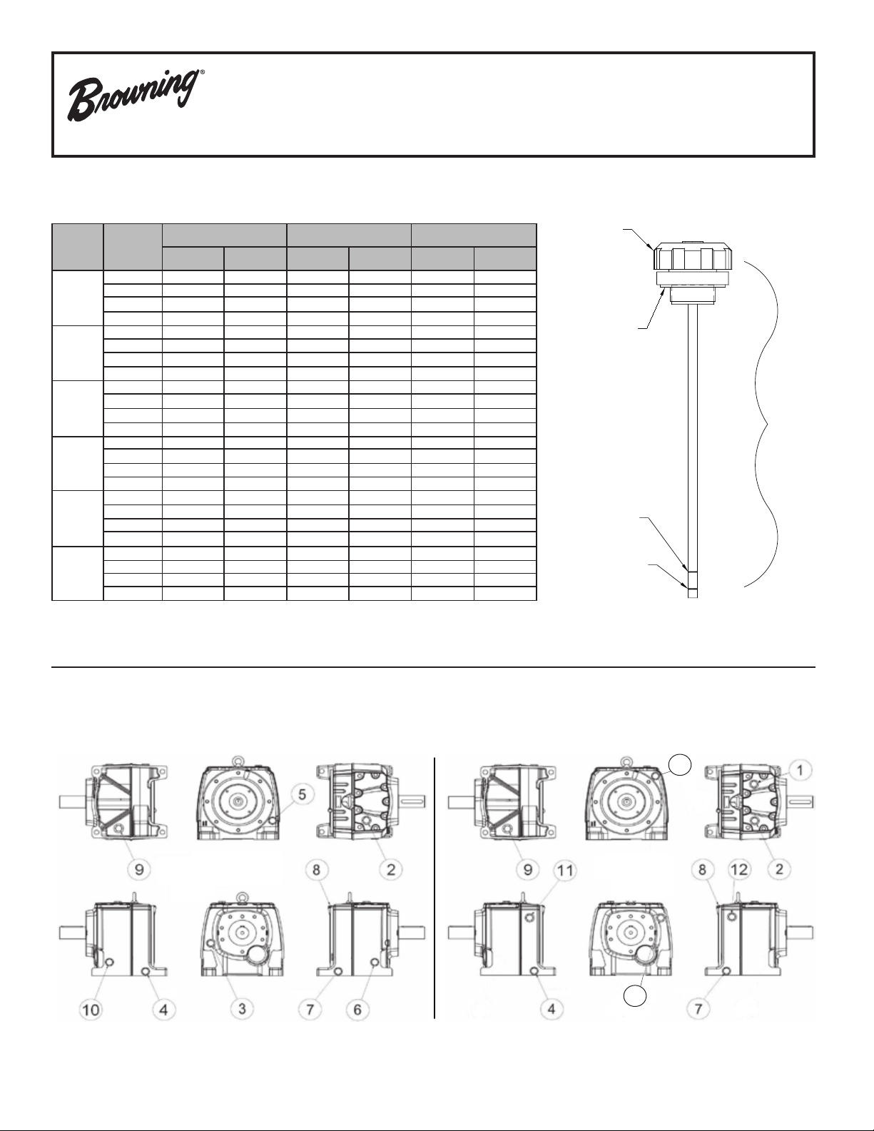
Page 4
Single Reduction Mounting Positions
Frames 31 Thru 35
Foot Mounted
(with/without ange)
Flange Mounted (Footless)
4
Page 5
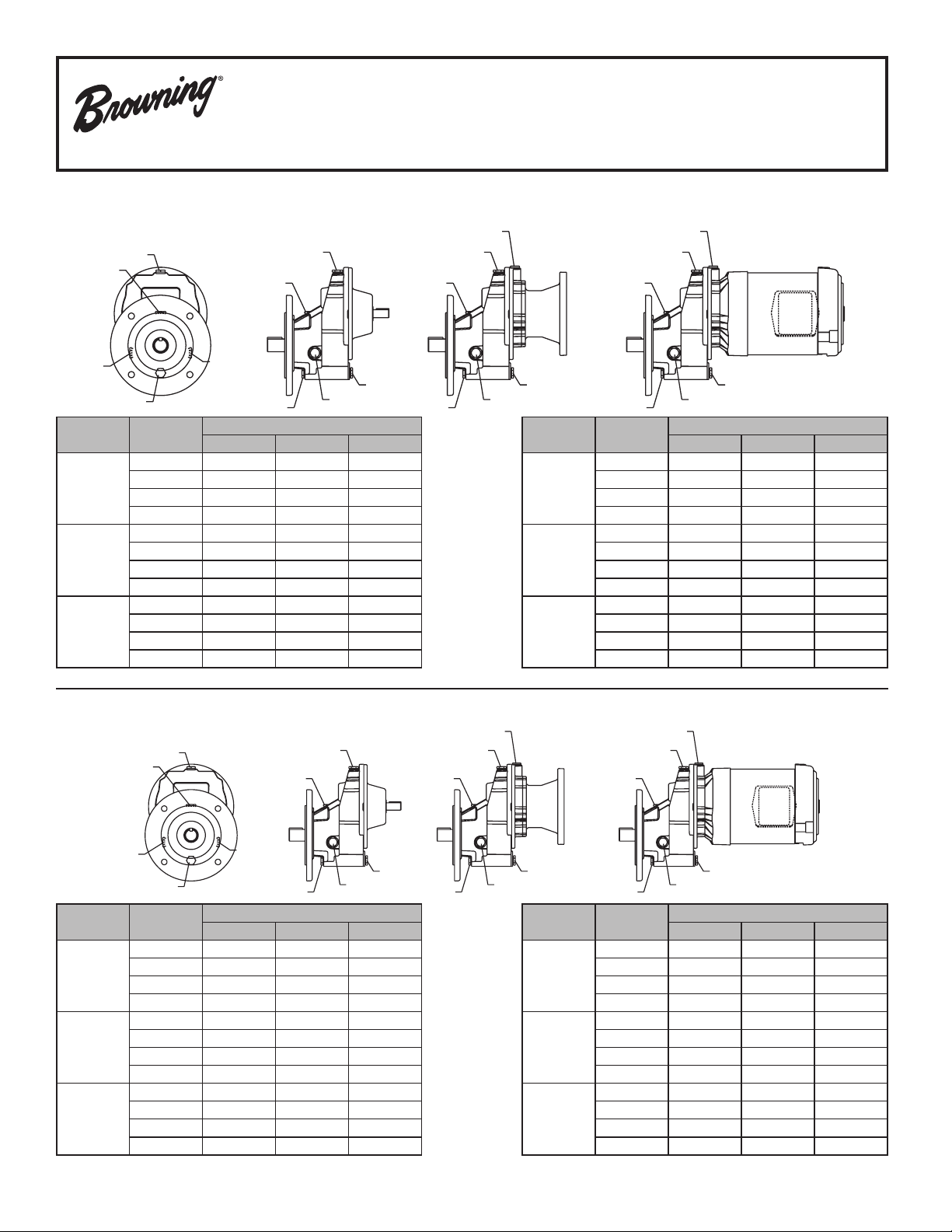
Single Reduction Plug Location and Assignments
2
1
6
3
4
5
2
4
6
11
8
5
6
4
2
1
8
5
6
4
2
Frames 31 Thru 35
Foot Mount - S, SB14, SBS, SBD2
1
6
3
Mounting
Position
B3
B6
B7
* Frame 32 only
2
4
Plug
Function
Breather 1 or 6 8 8
Level 2 or 3 2 or 3 2 or 3
Drain 4 4 4
Filling 1 1 1
Breather 3 3 or 8 3 or 8
Level 1 or 4 1 or 4 1 or 4
Drain 2 2 2
Filling 3 3 3
Breather 2 2 or 8 2 or 8
Level 1 or 4 1 or 4 1 or 4
Drain 3 3 3
Filling 2 2 2
Input Shaft C-Face Gearmotor
6
4
Type Unit
Input Shaft
C-Face
8
11
6
5
2
4
5
2
Mounting
Position
B8
V5
V6
Gearmotor
8
1
6
5
4
Plug
Function
Breather 4 or 5 4 or 5 4 or 5
Level 2 or 3 2 or 3 2 or 3
Drain 1 1 1
Filling 4 or 5 4 or 5 4 or 5
Breather 5 5 or 8 5 or 8
Level 1 1 1
Drain 4 4 4
Filling 5 5 5
Breather 4 4 4
Level 2 or 3 2 or 3 2 or 3
Drain 1 8 8
Filling 4 4 4
2
Type Unit
Input Shaft C-Face Gearmotor
Flange Mounted - Footless
Mounting
Position
B5
B52
B54
* Frame 32 only
Plug
Function
Breather 1 or 6 8 8
Level 2 or 3 2 or 3 2 or 3
Drain 4 4 4
Filling 1 1 or 8 1 or 8
Breather 3 3 or 8 3 or 8
Level 1 or 4 1 or 4 1 or 4
Drain 2 2 2
Filling 3 3 3
Breather 2 2 or 8 2 or 8
Level 1 or 4 1 or 4 1 or 4
Drain 3 3 3
Filling 2 2 2
Input Shaft C-Face Gearmotor
Type Unit
Input Shaft C-Face Gearmotor
Mounting
Position
B53
V1
V3
Plug
Function
Breather 4 or 5 4 or 5 4 or 5
Level 2 or 3 2 or 3 2 or 3
Drain 1 1 1
Filling 4 or 5 4 or 5 4 or 5
Breather 5 5 5
Level 1 1 1
Drain 4 4 4
Filling 5 5 or 8 5 or 8
Breather 4 4 4
Level 2 or 3 2 or 3 2 or 3
Drain 5 8 8
Filling 4 4 4
Input Shaft C-Face Gearmotor
Type Unit
5
Page 6
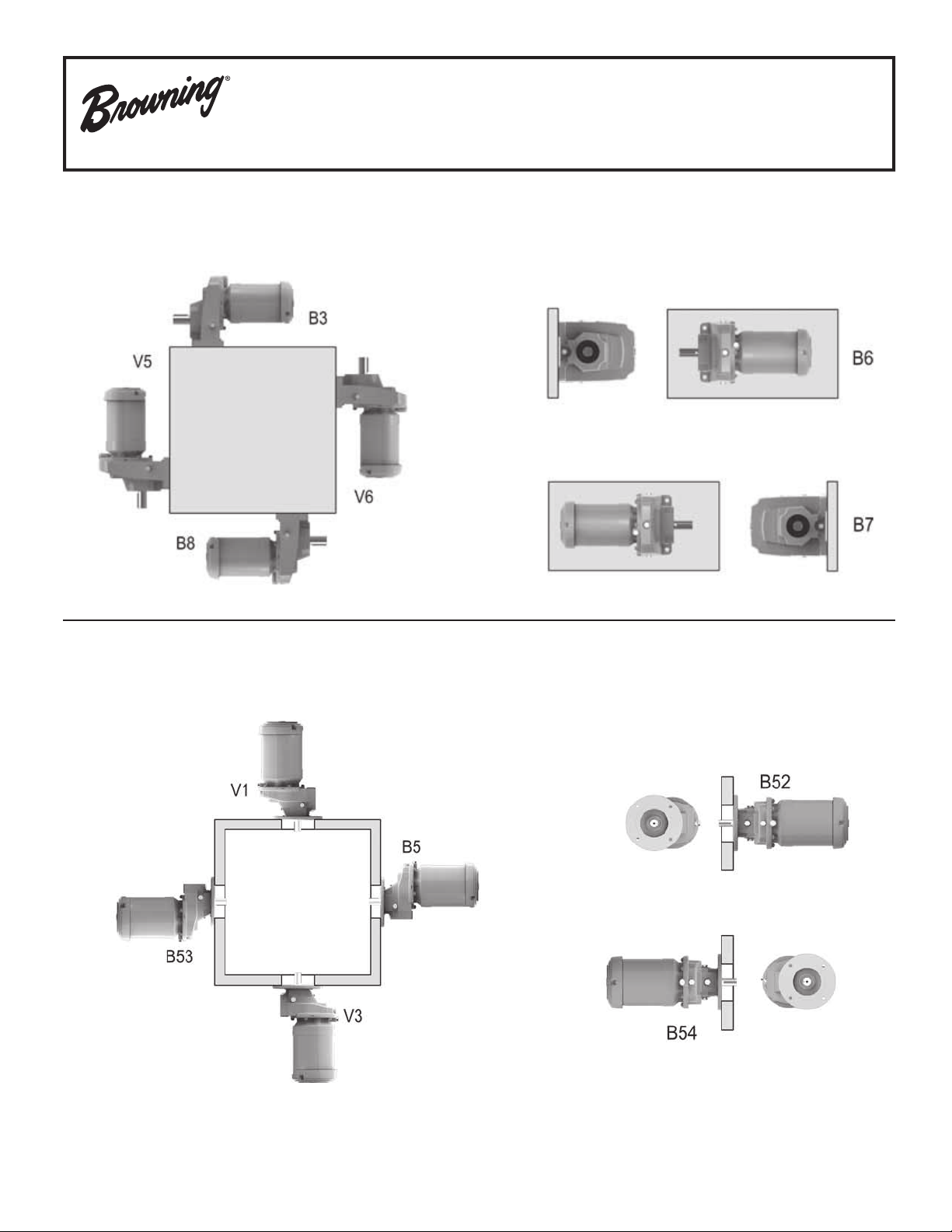
V5
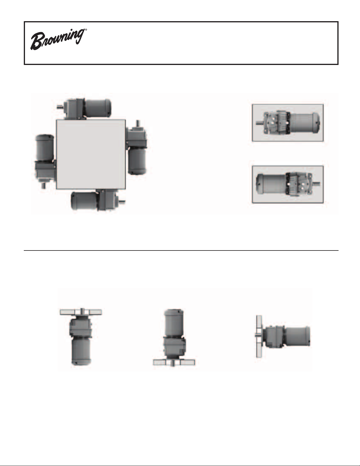
Multiple Reduction Mounting Positions
Frames 31 Thru 35
Foot Mounted (with/without ange)
B3
B6
B8
V3
V6
Flange Mounted (Footless)
V1
B7
B5
6
Page 7
Foot Mount
88
88
1
2
3
Multiple Reduction Plug Locations and Assignments
Frames 31 Thru 35
Input Shaft C-Face Gearmotor
1141
4
Mounting
Position
B3
B6
B7
Plug
Function
Breather 1 or 2 1, 2 or 8 1, 2 or 8
Level 3 3 3
Drain 4 4 4
Filling 1 or 2 1 or 2 1 or 2
Breather 3 3 or 8 3 or 8
Level ** ** **
Drain 4 4 4
Filling 3 3 3
Breather 4 4 or 8 4 or 8
Level 1 1 1
Drain 3 3 3
Filling 4 4 4
Input Shaft C-Face Gearmotor
** Double Reduction (except size 34) = 1, Triple Reduction = 2
Type Unit
Flange or Face Mount - Footless
1
2
3
Input Shaft C-Face Gearmotor
11 1
Mounting
Position
B8
V5
V6
4
Plug
Function
Breather 4 4 or 8 4 or 8
Level 3 3 3
Drain 1 or 2 1 or 2 1 or 2
Filling 4 4 4
Breather 4 8 8
Level 4 4 4
Drain 3 3 3
Filling 4 8 8
Breather 3 3 3
Level 1 or 2 1 or 2 1 or 2
Drain 4 8 8
Filling 3 3 3
Input Shaft C-Face Gearmotor
Type Unit
Mounting
Position
B5
V1
V3
44
Plug
Function
Breather 1 or 2 1, 2 or 8 1, 2 or 8
Level 3 3 3
Drain 4 4 4
Filling 1 or 2 1 or 2 1 or 2
Breather 4 8 8
Level 4 4 4
Drain 3 3 3
Filling 4 8 8
Breather 3 3 3
Level 1 or 2 1 or 2 1 or 2
Drain 4 8 8
Filling 3 3 3
Input Shaft C-Face Gearmotor
Type Unit
4
7
Page 8
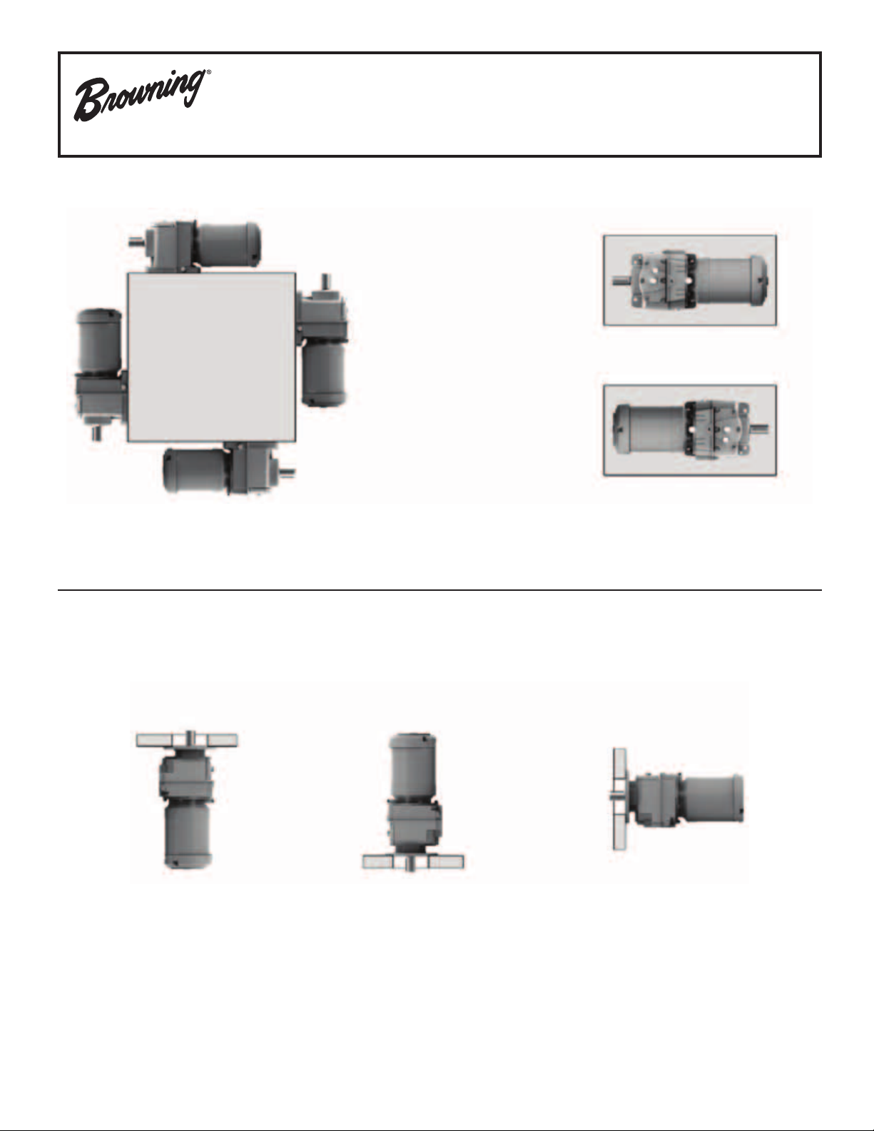
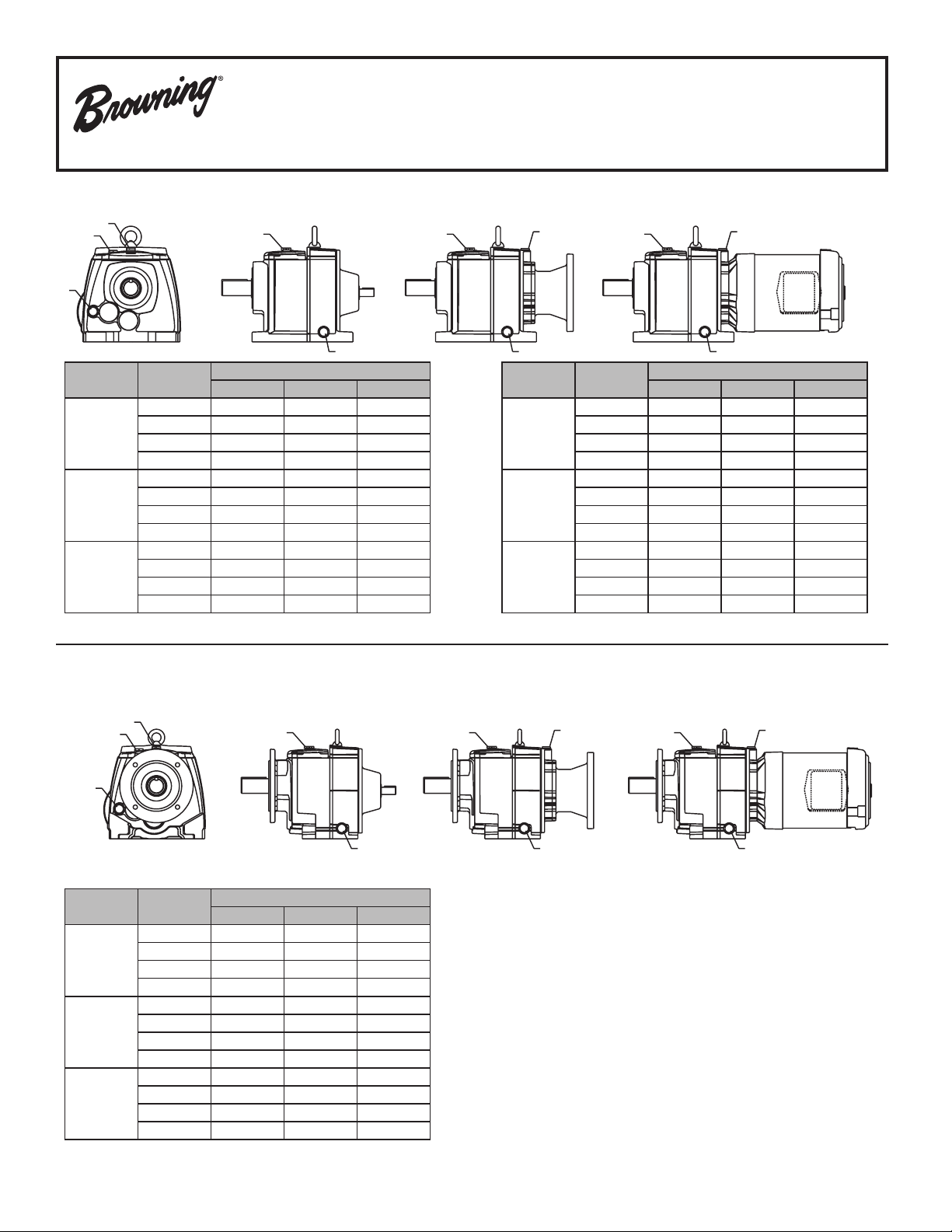
Multiple Reduction Mounting Positions
Frames 36 thru 38
Foot Mounted (with/without ange)
B3
V5
B6
V6
B7
B8
Flange Mounted
V3
V1
B5
8
Page 9
Multiple Reduction Plug Locations and Assignments
BREATHER
All Foot, Flange, and Face Mounted Units
Frames 36 thru 38
Mounting
Position
B3 and
B5
B6
B7
B8
V5 and
V1
V6 and
V3
* Alternative oil level indication plug for anged mounted units
** This location will have dipstick for monitoring oil level unless noted
*** Level plug positioned on 90 degree elbow tting
**** Sight tube supplied at position #2 for oil level indication
Plug
Function
Breather 2 2 2 2 2 2
Level ** 2 2 2 2 2 2
Drain 4 4 7 7 4 4
Filling 2 2 2 2 1 1
Breather 6 6 6 6 12 12
Level ** 6 6 6 6 12 12
Drain 10 10 10 10 4 4
Filling 6 6 6 6 7 7
Breather 10 10 10 10 11 11
Level ** 10 10 10 10 11 11
Drain 6 6 6 6 7 7
Filling 10 10 10 10 4 4
Breather 9 9 9 9 9 9
Level 3*** 3*** **** **** **** ****
Drain 2 2 2 2 2 2
Filling 4 4 6 6 9 9
Breather 5 5 5 5 13 13
Level ** 5 5 5 5 13 13
Drain 3 3 3 3 14 14
Filling 5 5 5 5 13 13
Breather 3** 3** 3** 3** 14 14
Level 6* 6* 3 3 14 14
Drain 5 8 5 8 13 13
Filling 3 3 3 3 14 14
Frame 36 Frame 37 Frame 38
Input
Shaft
C-face and
Gearmotor
Input
Shaft
C-face and
Gearmotor
Input
Shaft
C-face and
Gearmotor
GASKET
BOTTOM
OIL
MAX.
MIN.
DIPSTICK
OIL
Views
CbN36-37
13
CbN38
14
9
Page 10
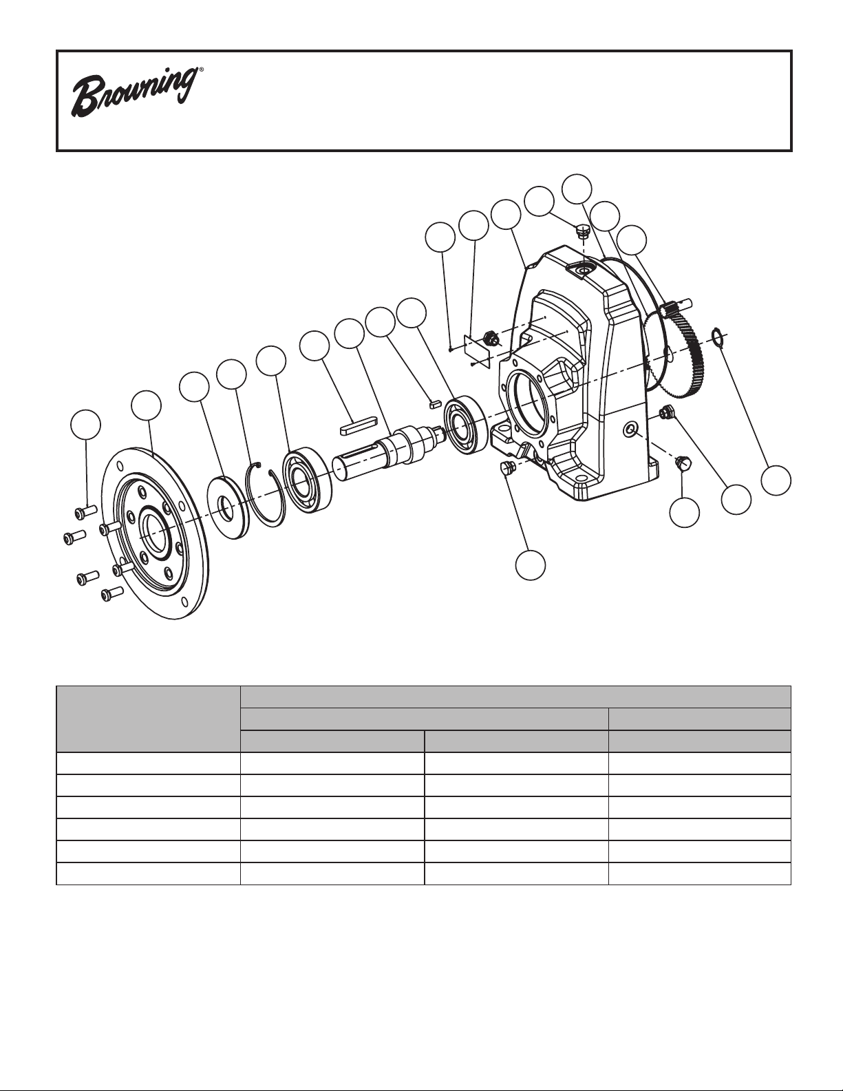
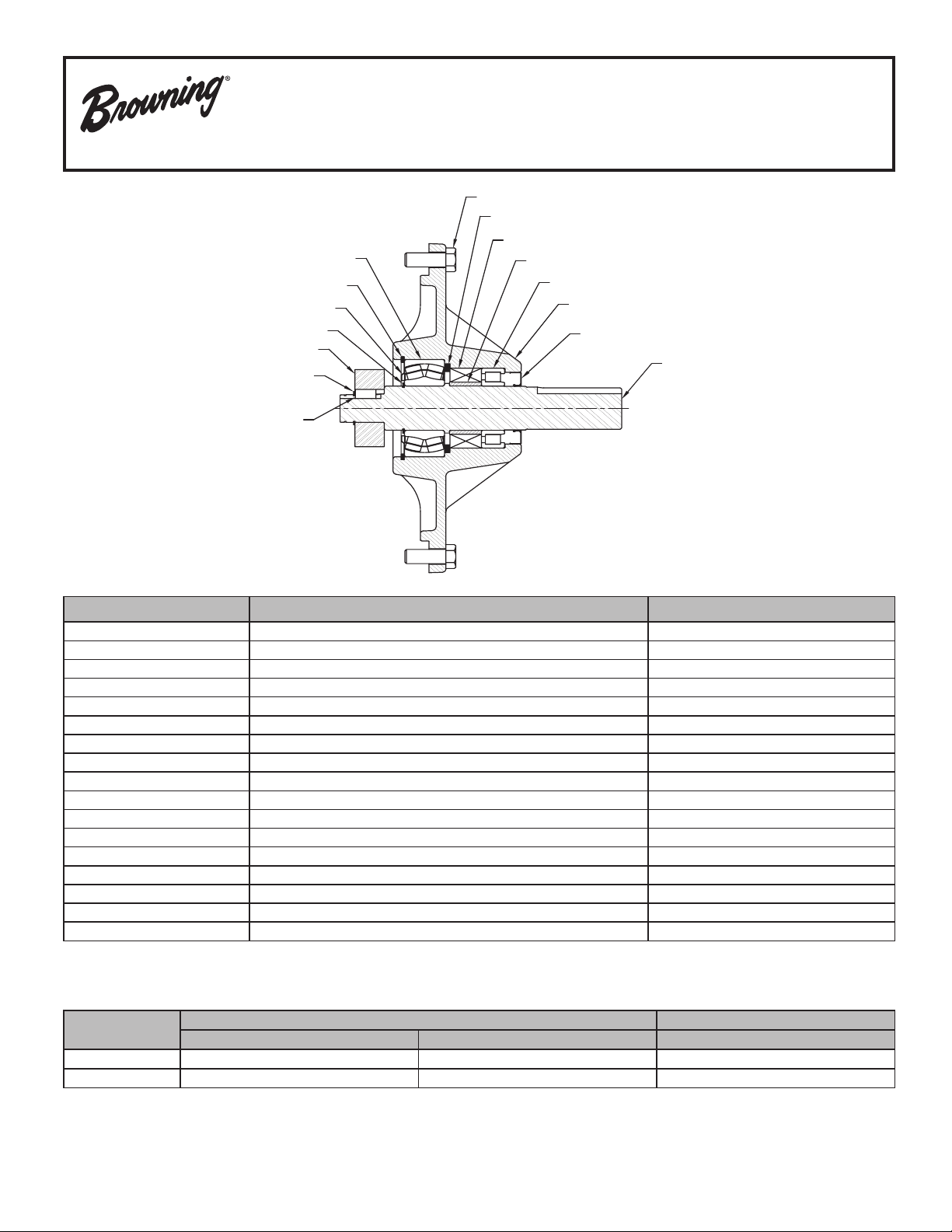
Single Reduction Parts Lists
009
090
187
130
061
077
031
080
062
284
282
001
255
097
052
042
128
258
256
257
CbN 30 - 35
10
Gear Frame
061 062 090
30 6205 ZZ 6005 25 x 52 x 7 DL, nitrile
31 6205 1RS 6304 25 x 52 x 7 DL, nitrile
32 6206 RS 6305 30 x 62 x 7 DL, nitrile
33 6308 RS 6307 40 x 90 x 8 DL, nitrile
34 6309 ZZ BHT C3 6308 45 x 100 x 8 DL, nitrile
35 6310 RS 6309 50 x 110 x 12 DL, nitrile
Bearings Seal (mm)
Item Description by Location
Page 11

CbN 30 - 35 (Quantity Per Unit)
Single Reduction Parts Lists
CbN 30 - 35
Rep Description 30 31 32 33 34 35
001 Housing 1 1 1 1 1 1
009 Output Flange Ring 1 1 1 1 1 1
031 Output Shaft 1 1 1 1 1 1
042 Pinion 1 1 1 1 1 1
052 Gear 1 1 1 1 1 1
061 Bearing Front 1 1 1 1 1 1
062 Bearing Back 1 1 1 1 1 1
077 Output Shaft Key 1 1 1 1 1 1
080 Gear Key 1 1 1 1 1 1
090 Oil Seal 1 1 1 1 1 1
Input "O" Ring Seal
097
(optional)
127 Bearing Snap Ring* 1 0 0 0 0 0
128 Gear Snap Ring 0 1 1 1 1 1
* Not illustrated.
** Design revision 4/03.
1 1 1 1 1 1
Rep Description 30 31 32 33 34 35
130 Bearing Snap Ring 1 1 1 1 1 1
140 Gear Spacer* 0 1** 1** 0 0 0
175 Screw for Face-Plate* 4 0 0 0 0 0
185 Washer for Gear* 1 0 0 0 0 0
186 Screw Washer* 1 0 0 0 0 0
187 Bolt 4 4 4 6 6 6
213 Flange Dowel Pin* 0 1 1 1 1 1
255 Breather Plug 0 1 1 1 1 1
256 Level Plug 0 2 2 2 2 2
257 Drain Plug 0 1 1 1 1 1
258 Drain Plug 0 1 1 1 1 1
282 Nameplate 1 1 1 1 1 1
284 Nameplate Pin 0 2 2 2 2 2
11
Page 12
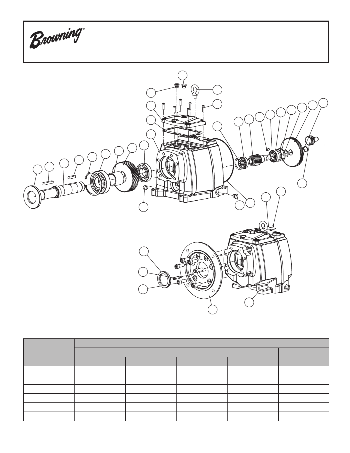
Double Reduction Parts List
CbN 30 - 35
254
090
077
031
076
130
061
140
051
062
254
092
255
002
099
001
250
193
161
063
257
041
097
080
282
064
111
284
138
144
042
052
128
213
187
Typical Maintenance Items - Bearings and Seals (Double Reduction)
Item Description by Location
Gear Frame
061 062 063 064 090
30 6205 6202 6300 6301 25 x 52 x 7 DL, nitrile
31 6206 ZZ BHT C3 6205 NJ 202 ECP 6202 35 x 62 x 6 DL, nitrile
32 6207 ZZ BHT C3 6206 60203 30203 42 x 72 x 8 DL, nitrile
33 6309 ZZ BHT C3 6208 30304 30205 52 x 100 x 10 DL, nitrile
34 6311 ZZ BHT C3 6310 30306 30306 62 x 120 x 12 DL, nitrile
35 6313 ZZ BHT C3 6310 33207 33207 72 x 140 x 12 DL, nitrile
12
Bearings Seal (mm)
001
009
Page 13
CbN 30 - 35 (Quantity Per Unit)
Double Reduction Parts List
CbN 30 - 35
Rep Description 30 31 32 33 34 35
001 Housing 1 1 1 1 1 1
002 Cover 1 1 1 1 1 1
009 Output Flange Ring 1 1 1 1 1 1
031 Output Shaft 1 1 1 1 1 1
041 Pinion Axis 3 1 1 1 1 1 1
042 Pinion (primary) 1 1 1 1 1 1
043 Pinion Axis 2 0 0 0 0 0 0
051 Gear Axis 4 1 1 1 1 1 1
052 Gear Axis 2 1 1 1 1 1 1
053 Gear Axis 3 0 0 0 0 0 0
061 Bearing Front Axis 4 1 1 1 1 1 1
062 Bearing Back Axis 4 1 1 1 1 1 1
063 Bearing Front Axis 2 1 1 1 1 1 1
064 Bearing Back Axis 2 1 1 1 1 1 1
065 Bearing Front Axis 3 0 0 0 0 0 0
066 Bearing Back Axis 3 0 0 0 0 0 0
076 Gear Key 1 1 1 1 1 1
077 Output Shaft Key 1 1 1 1 1 1
080 Gear Key 1 1 1 1 1 1
081 Gear Key Axis 3 0 0 0 0 0 0
090 Oil Seal 1 1 1 1 1 1
092 Flange Oil Seal (Opt.) 0 1 1 1 1 1
097 Input O-Ring (Opt.) 1 1 1 1 1 1
099 Cover Gasket 1 1 1 1 1 1
Bearing Spacer
111
Axis 2*
Bearing Spacer
112
Axis 3
Bearing Spacer Axis
114
3 *
115 Bearing Spacer Axis 2* 0 0 1 0 1 1
127 Bearing Snap Ring * 1 0 0 0 0 0
* Not Illustrated
0 0 0 1 0 0
0 0 0 0 0 0
0 0 0 0 0 0
Rep Description 30 31 32 33 34 35
128 Gear Snap Ring 0 1 1 1 1 1
130 Bearing Snap Ring 1 1 1 1 1 1
132 Bearing Snap Ring * 0 0 1 0 1 1
133 Bearing Snap Ring 0 0 0 0 0 0
134 Bearing Snap Ring * 0 0 0 0 0 0
138 Bearing Snap Ring 1 1 1 1 0 0
140 Gear Spacer Axis 4 0 1 1 1 1 1
143 Bearing Spacer 0 0 0 0 0 0
144 Gear Spacer (primary) 0 1 1 1 1 1
161 Flexible Wavy Washer * 0 0 0 1 1 1
162 Flexible Wavy Washer 0 0 0 0 0 0
163 Flexible Wavy Washer * 0 0 0 0 0 0
164 Flexible Wavy Washer * 0 0 1 0 0 0
175 Screw For Face Plate * 4 0 0 0 0 0
183 Input Cover Stud 0 4 5 6 4 8
185 Washer To Gear * 1 0 0 0 0 0
186 Screw Washer * 1 0 0 0 0 0
187 Fixing Screws 4 4 6 6 6 6
193 Cover Fixing Screw 4 4 6 6 8 8
213 Flange Dowel Pin 0 1 1 1 1 1
250 Lifting Eye 0 0 1 1 1 1
251 Plug * 0 0 1 0 1 1
252 Gear Case Plug 0 0 0 0 0 0
254 Drain Plug 0 1 1 1 1 1
255 Breather Plug 0 1 1 1 1 1
256 Level Plug 0 1 1 1 1 1
257 Drain PLug 0 1 1 1 1 1
282 Nameplate 1 1 1 1 1 1
13
Page 14

090
077
031
076
130
061
140
Triple Reduction Parts List
CbN 30 - 35
254
255
002
099
001
062
051
250
193
064
183
043
080
063
143
138
144
052
128
042
256
065
053
081
041
066
162
112
133
252
213
187
092
Typical Maintenance Items - Bearings and Seals (Triple Reduction)
Item Description by Location
Gear Frame
061 062 063 064 065 066 090
30 6205 6202 6201 6201 6300 6300 25 x 52 x 7 DL, nitrile
31 6206 ZZ BHT C3 6205 6201 6202 6202 6202 35 x 62 x 6 DL, nitrile
32 6207 ZZ BHT C3 6206 6203 6203 30203 30203 42 x 72 x 8 DL, nitrile
33 6309 ZZ BHT C3 6208 6304 6205 30304 30304 52 x 100 x 10 DL, nitrile
34 6311 ZZ BHT C3 6310 6306 6306 30305 30305 62 x 120 x 12 DL, nitrile
35 6313 ZZ BHT C3 6310 6306 6207 32207 32207 72 x 140 x 12 DL, nitrile
Bearings Seal (mm)
097
257
001
009
DL = Double lipped.
14
Page 15

Triple Reduction Parts List
CbN 30 - 35
CbN 30 - 35 (Quantity Per Unit)
Rep Description 30 31 32 33 34 35 Rep Description 30 31 32 33 34 35
001 Housing 1 1 1 1 1 1 128 Gear Snap Ring 0 1 1 1 1 1
002 Cover 1 1 1 1 1 1 130 Bearing Snap Ring 1 1 1 1 1 1
009 Output Flange Ring 1 1 1 1 1 1 132 Bearing Snap Ring * 0 0 1 0 1 1
031 Output Shaft 1 1 1 1 1 1 133 Bearing Snap Ring 0 1 1 1 1 1
041 Pinion Axis 3 1 1 1 1 1 1 134 Bearing Snap Ring * 1 0 0 0 0 0
042 Pinion (primary) 1 1 1 1 1 1 138 Bearing Snap Ring 1 1 1 1 0 0
043 Pinion Axis 2 1 1 1 1 1 1 140 Gear Spacer Axis 4 0 1 1 1 1 1
051 Gear Axis 4 1 1 1 1 1 1 143 Bearing Spacer 0 0 0 1 0 0
052 Gear Axis 2 1 1 1 1 1 1 144 Gear Spacer (primary) 0 1 1 1 1 1
053 Gear Axis 3 1 1 1 1 1 1 161 Flexible Wavy Washer * 0 0 0 1 0 0
061 Bearing Front Axis 4 1 1 1 1 1 1 162 Flexible Wavy Washer 0 0 0 1 1 1
062 Bearing Back Axis 4 1 1 1 1 1 1 163 Flexible Wavy Washer * 0 0 1 0 0 0
063 Bearing Front Axis 2 1 1 1 1 1 1 164 Flexible Wavy Washer * 0 0 0 0 0 0
064 Bearing Back Axis 2 1 1 1 1 1 1 175 Screw For Face Plate * 4 0 0 0 0 0
065 Bearing Front Axis 3 1 1 1 1 1 1 183 Input Cover Stud 0 4 5 6 4 8
066 Bearing Back Axis 3 1 1 1 1 1 1 185 Washer To Gear * 1 0 0 0 0 0
076 Gear Key 1 1 1 1 1 1 186 Screw Washer * 1 0 0 0 0 0
077 Output Shaft Key 1 1 1 1 1 1 187 Fixing Screws 4 4 6 6 6 6
080 Gear Key 1 1 1 1 1 1 193 Cover Fixing Screw 4 4 6 6 8 8
081 Gear Key Axis 3 1 1 1 1 1 1 213 Flange Dowel Pin 0 1 1 1 1 1
090 Oil Seal 1 1 1 1 1 1 250 Lifting Eye 0 0 1 1 1 1
092 Flange Oil Seal (Opt.) 0 1 1 1 1 1 251 Plug * 0 0 1 0 1 1
097 Input O-Ring (Opt.) 1 1 1 1 1 1 252 Gear Case Plug 0 1 1 1 1 1
099 Cover Gasket 1 1 1 1 1 1 254 Drain Plug 0 1 1 1 1 1
Bearing Spacer Axis
111
2*
112 Bearing Spacer Axis 3 0 0 0 1 1 1 256 Level Plug 0 1 1 1 1 1
Bearing Spacer Axis
114
3 *
Bearing Spacer Axis
115
2*
127 Bearing Snap Ring * 1 0 0 0 0 0
* Not Illustrated
0 0 0 1 0 0 255 Breather Plug 0 1 1 1 1 1
0 1 1 0 0 0 257 Drain PLug 0 1 1 1 1 1
0 0 0 0 0 0 282 Nameplate 1 1 1 1 1 1
15
Page 16

090
130
127
061
501
213
Multiple Reduction Parts List
CbN 36 - 38
009
187
502
051
076
031
077
062
099
002
193
254
250
261
282
284
042
052
186
185
090
130
127
061
187
501
213
077
009
031
076
252
133
051
065
502
500
251
062
132
041
254
081
063
099
002
500
193
053
041
066
250
080
257
261
064
001
282
257
284
063
001
Double Reduction
186
042
052
117
064
080
043
Triple Reduction
185
111
138
16
Page 17

CbN 36 to 38 (Quantity Per Unit)
Multiple Reduction Parts List
CbN 36 - 38
Item # Description
001 Housing 1 1 1 1 1 1 127 Bearing snap ring 0 1 1 0 1 1
002 Cover 1 1 1 1 1 1 128 Washer Gear Axis 2 0 0 0 1 0 0
009 Output Flange Ring 1 1 1 1 1 1 130 Bearing Snap Ring 1 1 1 1 1 1
031 Output Shaft 1 1 1 1 1 1 132 Bearing Snap Ring 1 1 1 0 0 0
041 Pinion Axis 3 0 0 0 1 1 1 133 Bearing Snap Ring 0 0 0 1 1 1
042 Pinion Axis 1 1 1 1 1 1 1 137 Snap Ring 0 1 1 0 0 0
043 Pinion Axis 2 0 0 0 1 1 1 138 Snap Ring 0 1 0 1 1 1
051 Gear Axis 4 1 1 1 1 1 1 142
052 Gear Axis 2 1 1 1 1 1 1 154 Gear Spacer 0 0 0 1 0 0
053 Gear Axis 3 0 0 0 1 1 1 187 Fixing Screws 7 9 11 7 9 11
061 Bearing Front Axis 4 1 1 1 1 1 1 193
062 Bearing Back Axis 4 1 1 1 1 1 1 213 Flange Roll Pin 1 1 2 1 1 2
063 Bearing Front Axis 2 1 1 1 1 1 1 250 Lifting eye 1 1 1 1 1 1
064 Bearing Back Axis 2 1 1 1 1 1 1 251 Bore plug 1 1 1 0 0 0
065 Bearing Front Axis 3 0 0 0 1 1 1 252 Gearcase Bore plug 0 0 0 1 1 1
066 Bearing back Axis 3 0 0 0 1 1 1 254 Plug 5 5 7 5 5 7
076 Gear Key 1 1 1 1 1 1 257 Magnetic drain plug 1 1 1 1 1 1
077 Output Shaft Key 1 1 1 1 1 1 261 Dipstick/Breather 1 1 1 1 1 1
080 Gear Key 1 1 1 1 1 1 282 Nameplate 1 1 1 1 1 1
081 Gear Key Axis 3 0 0 0 1 1 1 284 Rivet 2 2 2 2 2 2
090 Oil seal 1 1 1 1 1 1 500 Nilos ring Axis 2 0 0 1 0 0 1
099 Cover gasket 1 1 1 1 1 1 501 Nilos ring Axis 4 front 1 1 1 1 1 1
111 Bearing Spacer Axis 2 0 0 0 1 0 1 502 Nilos ring Axis 4 back 0 0 1 0 0 1
Double Reduction Triple Reduction
36 37 38 36 37 38 36 37 38 36 37 38
Item # Description
Bolt For Gear
Axis 2
Cover Fixing
Screws
Double Reduction Triple Reduction
1 2 2 0 1 2
9 12 11 9 12 11
117 Shims 0 0 0 0 0 1 517 Snap Ring
119 Bearing Spacer Axis 2 0 0 0 0 1 1
Typical Maintenance Items - Bearings and Seals (Double Reduction)
Item Description
Gear Frame
061 062 063 064 090
36 22217E NJ214 ECP 22308E 22208E 85x150x12 DL, nitrile
37 22220 NJ217 22311 22310E 100x180x12 DL, nitrile
38 23124E NJ220 22312E 22312E 120x200x14 DL, nitrile
Bearings Seal (mm)
Typical Maintenance Items - Bearings and Seals (Triple Reduction)
Item Description
Gear Frame
061 062 063 064 065 066 090
36 22217E NJ214 ECP 32206B 32207 22308E 22208E 85x150x12 DL, nitrile
37 22220 NJ217 30308 30308 22311 22310E 100x180x12 DL, nitrile
38 23124E NJ220 30310 30310 22312E 22312E 120x200x14 DL, nitrile
Bearings Seal (mm)
1 0 0 1 0 0
17
Page 18

C-Face Input Parts Lists (Quantity Per Unit)
CbN 30 - 38
16
15
14
9
10
11
8
18
3
17
6
5
2
7
1
19
4
13
No. Description 56C 140TC 180TC 210TC 250TC 280TC
1 Non-Metallic Liner 1 1 1 1 1 1 1
2 Seal 1 1 1 1 1 1 1
3 Motor Adapter 1 1 1 1 1 1 1
4 Capscrew 6 6 6 6 6 6 6
5 Bearing 1 1 1 1 1 1 1
6 Spacer 1 † 1 † 1 1 1 1 1
7 Input Shaft 1 1 1 1 1 1 1
8 Bearing 1 1 1 1 1 1 1
9 Internal Snap Ring 1 1 1 1 1 1 1
10 Key* 1 1 1 1 1 1 1
11 Pinion 1 1 1 1 1 1 1
12 Nuts† ** ** ** ** ** ** **
13 Studs† ** ** ** ** ** ** **
14 Adapter Flange 1 † 1 † 1 1 1 1 1
15 Gasket 1 † 1 † 1 1 1 1 1
16 Plug (1/4") 1 † 1 † 1 1 1 1 1
17 Motor Adapter Flange N/A N/A N/A N/A 1*** 1 N/A
18 Backstop Kit (option) 1 † 1 † 1 1 1 1 1
19 Seal 0 0 0 0 0 1 1
* Pin used with 9mm, 12mm, 15mm and 18mm pinion.
** Depending on gear frame size: 31 = 4, 32 = 5, 33 = 6, 34 = 4, 35 = 8.
***Applicable to size 33.
† Not applicable to size 30.
Not applicable to sizes 36 and 37
Gear Frame (s) Motor Frame (s)
30 56C, 140TC 6006 2RS 6004 2RS 55 X 30 X 10 (mm)
31 to 36 56C, 140TC 6007 ZZ C3 6207 ZZ C3 2 X 1.375 X .312
31 to 37 180TC 6012 ZZ C3 6210 ZZ C3 4 X 2.250 X .468
32 to 37 210TC 6012 ZZ C3 6210 ZZ C3 4 X 2.250 X .468
38 210TC 6014 ZZ C3 NJ210 4.438 X 2.625 X .437
34 to 38 250TC , 280TC 6014 ZZ C3 NJ210 4.438 X 2.625 X .437
35 * 320TC 6216 ZZ C3 NJ310 140 X 90 X 12 (mm)
* For 36 through 38 frame with 320TC input, refer to opposing page
12
Bearings Oil Seal (inches)
5 8 9
320TC
18
Page 19

C-Face Input Parts Lists (Quantity Per Unit)
8
9
CbN 36 - 38
10
11
12
13
14
15
16
17
18
19
20
No. Description of Part 320TC/360TC
1 Setscrew 1
2 Motor Coupling 1
3 Motor Adapter 1
4 Coupling Sleeve 1
5 Seal 1
6 Internal Snap Ring 1
7 Bearing 1
8 External Snap Ring 1
9 Adapter Flange 1
10 Capscrew 8
11 Backstop 1
12 Capscrew 12
13 Spacer 1
14 Bearing 1
15 Internal Snap Ring 1
16 Bearing Seal 1
17 Pinion 1
18 Key 1
19 External Snap Ring 1
20 Input Shaft 1
7
6
5
4
3
2
1
Gear Bearings Oil Seal (inches)
Frame 7 14 9
36 to 38 6216 ZZ C3 NJ310 140 x 110 x 12 (mm) nitrile
19
Page 20

Gearmotor Input Parts Lists (Quantity Per Unit)
CbN 30 - 38
1
254
11
4
6
10
3
5
9
8
2
183
7
184
No. Description 30 31 32 33 34 35
1 Motor Adapter 1 1 1 1 1 1
2 Input Shaft 1 1 1 1 1 1
3 Pinion 1 1 1 1 1 1
4 Internal Snap Ring 1 1 1 1 1 1
5 Bearing Cap** † 1 1 1 1 1
6 Bearing 1 1 1 1 1 1
7 Adapter Flange † 1 1 1 1 1
8 External Snap Ring 1 1 1 1 1 1
9 Seal 1 1 1 1 1 1
10 Pinion Pin 1 1 1* 1* 1* 1*
11 Capscrew** † 2 2 2 2 2
183 Stud 4 4 5 6 4 8
184 Nut 4 4 5 6 4 8
254 Plug (or Breather) † 1 1 1 1 1
* Key used with 23mm and 32mm pinion.
** Explosionproof motor only, except on frame 30.
† Not applicable to size 30.
Gear Frame Motor Frame
30 56, 140T 6005 ZZ C3 47 x 25 x 7 (mm)
31 48 6005 ZZ C3 1.50 x .937 x .250
31 to 37
38 210T 6310 ZZ C3 3.500 x 2.250 x .375
33 250T 6209 ZZ C3 2.875 x 1.750 X .375
34 to 38 250T , 280T 6310 ZZ C3 3.500 x 2.250 x .375
35 to 38 320T 6311 ZZ C3 3.875 x 2.5 x .470
56, 140T 6007 ZZ C3 2.25 x 1.375 x .312
180T, 210T 6207 ZZ C3 2.25 x 1.375 x .312
Bearings Seal (inches)
6 9
20
Page 21

AP Input Shaft Parts Lists (Quantity Per Unit)
CbN 30 - 35
2
3
13
7
6
8
10
4
5
1
12
11
No. Description 30 31 32 33 34 35
1 Seal 1 1 1 1 1 1
2 Nuts 1 4 5 6 4 8
3 Studs 4 4 5 6 4 8
4 Housing 1 1 1 1 1 1
5 External Snap Ring 1 1 1 1 1 1
6 Bearing 1 1 1 1 1 1
7 Spacer 0 1 1 1 1 1
8 Bearing 1 1 1 1 1 1
9 Input Shaft 1 1 1 1 1 1
10 Internal Snap Ring 1 1 1 1 1 1
11 Pinion 1 1 1 1 1 1
12 Key* 1 1 1 1 1 1
13 Backstop Kit (Option) † 1 1 1 1 1
* Pin used with 9mm, 15mm and 18mm pinion.
† Not applicable to size 30.
9
Gear Frame
30 6203 2RS 6204 2RS 28 x 17 x 7 (mm) DL, nitrile
31, 32 6206 ZZ C3 6207 ZZ C3 1.875 x 1.125 x .25 DL, nitrile
33 6308 ZZ C3 6309 ZZ C3 2.5 x 1.50 x .312 DL, nitrile
34 NJ209 6311 ZZ C3 2.5 x 1.50 x .312 DL, nitrile
35 NJ210 6312 ZZ C3 3.188 x 1.938 x .438 DL, nitrile
6 8 1
Bearings Oil Seal (inches)
21
Page 22
AP Input Shaft Parts Lists (Quantity Per Unit)
15
CbN 36 - 38
14
13
8
10
16
5
11
17
12
7
6
4
1
9
No. Description of Part All Reductions
1 Seal 1
2 Nuts 0
3 Studs 0
4 Housing 1
5 External Snap Ring 1
6 Bearing 1
7 Spacer 1
8 Bearing 1
9 Input Shaft 1
10 Internal Snap Ring 1
11 Pinion 1
12 Key 1
13 Backstop Kit (optional) 1
14 Spacer 1
15 Bolt 8
16 Bearing Seal 1
17 External Snap Ring 1
Gear Bearings Seal (inches)
Frame 6 8 1
36 & 37 NJ2210 22310 3.188 x 1.938 x .438 DL, nitrile
38 32213 32313 3.250 x 2.500 x .375, DL, nitrile
22
Page 23

TEFC Intergral "Modular Motor" Parts List
Frames 56, 140T Frames 180T, 210T, 250T, A280T
Part # Description Qty.
1 Fan Cover 1
2 Self Tapping Screw 3
3 Hex Nut 1
4 Stud 1
5 Retaining Snap Ring 1
6 Fan 1
7 Bracket 1
8 Screw 4
9 Bushing 4
10 Plastic Plug 4
11 Ball Bearing 1
12 Rotor Assembly (includes items 13 & 14) 1
13 Shaft 1
14 Rotor Core 1
15 Wound Stator Assembly 1
16 Gasket 1
17 Outlet Box Base 1
18 Self Tapping Screw 2
19 Outlet Box Cover 1
20 Self Tapping Screw 2
Part # Description Qty.
1 Fan Cover 1
2 Self Tapping Screw 4
3 Hex Nut 1
4 Stud 1
5 Fan 1
6 Bracket 1
7 Hex Head Bolt 4
8 Lifting Lug 1
9 Hex Countersunk Pipe Plug 2
10 Ball Bearing 1
11 Rotor Assembly (includes items 12 & 13) 1
12 Shaft 1
13 Rotor Core 1
14 Wound Stator Assembly 1
15 Gasket 1
16 Outlet Box Base 1
17 Self Tapping Screw 2
18 Outlet Box Cover 1
19 Self Tapping Screw 2
Browning, Emerson and Emerson Industrial Automation are trademarks of
Emerson Electric Co. or one of its affiliated companies.
©2007, 2010, 2012 Emerson Power Transmission Corp., All Rights Reserved.
MCIM12004E • Form# 8772E • Printed in USA
23
 Loading...