

Emerson CBA730-SR, CBA830-SR-M3, CBA730-SR-M3, CBA830-SR, CBA830-SR-M3HW Service Instructions Manual
...Page 1
Service Instructions
137463E Rev. D
August 2015
CBAX30 Spring-Return Series Pneumatic Actuators
Disassembly and Reassembly
Page 2

Page 3

Service Instructions
137463E Rev. D
Table of Contents
Section 1: Introduction
1.1 General Service Information ........................................................................... 1
1.2 Denitions ..................................................................................................... 2
1.3 General Safety Information ............................................................................ 2
1.4 Bettis Reference Materials .............................................................................. 3
1.5 Service Support Items .................................................................................... 3
1.6 Lubrication Requirements .............................................................................. 3
1.7 General Tool Information ............................................................................... 3
1.8 Actuator Weight ............................................................................................ 4
1.9 Actuator Storage ............................................................................................ 4
1.10 Actuator Installation ...................................................................................... 4
1.11 Actuator Start-up ........................................................................................... 5
1.12 Actuator Operation ........................................................................................ 6
Table of Contents
August 2015
Section 2: Actuator Disassembly
2.1 General Disassembly ...................................................................................... 7
2.2 Spring Cylinder Disassembly ........................................................................... 8
2.3 Housing Disassembly ..................................................................................... 9
Section 3: Actuator Reassembly
3.1 General Reassembly ..................................................................................... 10
3.2 Housing Reassembly .................................................................................... 10
3.3 Spring Cylinder Reassembly .......................................................................... 13
Section 4: Actuator Testing
4.1 Actuator Testing .......................................................................................... 16
4.2 Return to Service .......................................................................................... 17
Section 5: Field Conversions
5.1 Fail Mode Reversal (CW to CCW, or CCW to CW) .......................................... 18
Section 6: Troubleshooting
6.1 Fault Insertion .............................................................................................. 19
6.2 Operational Test ........................................................................................... 20
Section 7: Removal and Decommissioning
7.1 Removal and Decommissioning ................................................................... 21
ITable of Contents
Page 4

Table of Contents
August 2015
Section 8: Document Revision ��������������������������������������������22
Appendix A: List of Tables ���������������������������������������������������23
Appendix B: List of Drawings ����������������������������������������������24
Service Instructions
137463E Rev. D
B.1 Part No. VA129743, CBA300-SRX Assembly Drawing ................................... 24
B.2 Part No. 129745, CBA300-SRX-M3HW Assembly Drawing ........................... 25
II Table of Contents
Page 5

Service Instructions
137463E Rev. D
Section 1: Introduction
1�1 General Service Information
1.1.1 This service procedure is offered as a guide to enable general maintenance to be
performed on Bettis™ CBAX30-SR spring-return series actuators. The following is
a list of general CBAX30 SR model numbers:
Table 1� CBAX30-SR Model Numbers
MODEL (1) MODEL (1) MODEL (1)
CBA730-SR CBA730-SR-M3 CBA730-SR-M3HW
CBA830-SR CBA830-SR-M3 CBA830-SR-M3HW
CBA930-SR CBA930-SR-M3 CBA930-SR-M3HW
CBA1030-SR CBA1030-SR-M3 CBA1030-SR-M3HW
(1) Also includes actuator models with –10 and –11 as a sufx
Section 1: Introduction
August 2015
NOTE:
When the actuator model number has “-S” as a sufx then the actuator is special and may
have some differences that may not be included in this procedure.
1.1.2 Normal recommended service interval for this actuator series is ve years.
NOTE:
Storage time is counted as part of the service interval.
1.1.3 This procedure is applicable with the understanding that all electrical power and
pneumatic pressure has been removed from the actuator.
1.1.4 Remove all piping and mounted accessories that will interfere with the module(s)
that are to be worked on.
1.1.5 This procedure should only be implemented by a technically competent technician
who should take care to observe good workmanship practices.
1.1.6 Numbers in parentheses, ( ) indicate the bubble number (reference number) used
on the Bettis assembly drawing and Actuator Parts List.
1.1.7 When removing seals from seal grooves, use a commercial seal removing tool or a
small screwdriver with sharp corners rounded off.
1.1.8 Use a non-hardening thread sealant on all pipe threads.
CAUTION: FOLLOW MANUFACTURER'S INSTRUCTIONS
Apply the thread sealant per the manufacturer’s instructions.
1.1.9 Bettis recommends that disassembly of the actuator should be done in a clean
area on a workbench.
Introduction
1
Page 6
Section 1: Introduction
August 2015
1�2 Definitions
WARNING:
If not observed, user incurs a high risk of severe damage to actuator and/or fatal injury to personnel.
CAUTION:
If not observed, user may incur damage to actuator and/or injury to personnel.
NOTE:
Advisory and information comments provided to assist maintenance personnel to carry out
maintenance procedures.
Service Instructions
137463E Rev. D
NOTE:
This product is only intended for use in large-scale xed installations excluded from the
scope of Directive 2011/65/EU on the restriction of the use of certain hazardous substances
in electrical and electronic equipment (RoHS 2).
M3:
Jackscrew or jackscrew assembly
M3HW:
Jackscrew assembly with handwheel
ES:
Extended Stop(s)
1�3 General Safety Information
1.3.1 Products supplied by Bettis, in its “as shipped” condition, are intrinsically safe if the
instructions contained within this Service Instruction are strictly adhered to and
executed by well trained, equipped, prepared and competent personnel.
WARNING: FOLLOW WARNING AND CAUTION SIGNS
For the protection of personnel working on Bettis actuators, this procedure should be
reviewed and implemented for safe disassembly and reassembly. Close attention should be
noted to the WARNINGS, CAUTIONS and NOTES contained in this procedure.
2
Introduction
Page 7

Service Instructions
137463E Rev. D
WARNING: FOLLOW COMPANY SAFETY PROCEDURES
This procedure should not supersede or replace any customer’s plant safety or work
procedures. If a conict arises between this procedure and the customer’s procedures, the
differences should be resolved in writing between an authorized customer's representative
and an authorized Bettis representative.
1�4 Bettis Reference Materials
1.4.1 CBAX30-SR assembly drawing use part number VA129743.
1.4.2 CBBX30-SR-M3HW assembly drawing use part number 129745.
1�5 Service Support Items
1.5.1 Bettis Service Kit.
1.5.2 Commercial leak testing solution.
1.5.3 Non-hardening thread sealant.
Section 1: Introduction
August 2015
1�6 Lubrication Requirements
1.6.1 The actuator should be relubricated at the beginning of each service interval using
the following recommended lubricants.
NOTE:
Lubricants other than those listed in steps 1.6.2 should not be used without prior written
approval of Bettis Product Engineering. The lubricant item number on some assembly
drawings is item (5) while the Bettis service kits lubricant item number is item number (500).
1.6.2 All temperature services (-50°F to +350°F)/(-45.5°C to 176.6°C) use Bettis ESL-5
lubricant. ESL-5 lubricant is contained in the Bettis module service kit in tubes and
the tubes are marked ESL-4, 5 and 10 lubricant.
1�7 General Tool Information
1.7.1 All threads on CBAX30-SR series actuators are Inch Unied and NPT.
1.7.2 All tools/Hexagons are American Standard inch. Two adjustable wrenches, Allen
wrench set, small standard screwdriver with sharp edges rounded off, medium size
standard screwdriver, diagonal cutting pliers, external snap ring pliers, at le, drive
ratchet / deep well socket set and torque wrench (up to 2,000 inch pounds / 226 N-m).
Introduction
3
Page 8

Section 1: Introduction
August 2015
1�8 Actuator Weight
Table 2� Actuator Weight
Service Instructions
137463E Rev. D
Approximate
Actuator Model
CBA730-SR40 (1) 158 71.7 CBA930-SR40 (1) 195 88.5
CBA730-SR60 (1) 160.5 72.8 CBA930-SR60 (1) 202 91.6
CBA730-SR80 (1) 163 73.9 CBA930-SR80 (1) 206.5 93.7
CBA730-SR100 (1) 164 74.4 CBA930-SR100 (1) 205 93.0
CBA830-SR40 (1) 180 81.6 CBA1030-SR40 (1) 220 99.8
CBA830-SR60 (1) 184.5 83.7 CBA1030-SR60 (1) 225.5 102.3
CBA830-SR80 (1) 188 85.3 CBA1030-SR80 (1) 233.5 105.9
CBA830-SR100 (1) 192.5 87.3
(1) When model has -M3HW add 8 pounds / 3.6 kilograms.
(2) Weight is for bare actuator without accessories or valve adaption.
1�9 Actuator Storage
For applications where the actuator is not placed into immediate service, it is
recommended that the actuator be cycled with regulated clean/dry pneumatic pressure
at least once per month. Indoor storage, if available, is recommended for all actuators.
Care should be taken to plug all open ports on actuator and controls to keep out foreign
particles and moisture. Actuators should not be stored in an atmosphere that is harmful to
resilient seals. Contact factory for extended storage period.
Approximate
Weight (2)
LB KG LB KG
Actuator Model
Weight (2)
1�10 Actuator Installation
1.10.1 Since there are many valve and actuator combinations, it is not practical to include
detailed instructions for each type. Mountings are designed to be as simple as
possible to keep the guess work out of the installation.
1.10.2 Actuators that are shipped from the factory with the travel stops adjusted for
approximately ninety degree rotation. Generally, it is necessary to make slight
travel stop adjustments once the actuator is installed onto the valve. Refer to the
valve manufacturer's recommendations for specic requirements. When the valve
has internal stops, the actuator should be adjusted at the same points.
NOTE:
The actual "stopping" should be done by the actuator. If the valve does not have internal
stops, adjust the actuator to the full open position. Using this as a reference point, rotate
the valve closed and adjust to the valve manufacturer's specications for total rotation.
1.10.3 Good instrument practices are also recommended. Clean/dry regulated
pneumatic pressure is essential for long service life and satisfactory operation.
It should be noted that new pneumatic lines often have scale and other debris in
them and these lines should be purged of all foreign material.
4
Introduction
Page 9

Service Instructions
137463E Rev. D
NOTE:
Scale and debris can damage control valves, solenoids and seals.
1�11 Actuator Start-up
1.11.1 Prestart-up checks
1. Inspect to ensure the unit has been mounted onto valve properly. Gear ange
mounting bolts, stem key, set screw(s) are installed and secured.
2. No tubing damaged or accessories dislodged during the shipping or the
installation.
3. Indicated position conrms valve position.
4. All switching valves in normal operating position as per
SCHEMATIC / INSTRUCTIONS.
1.11.2 Check Connections
1. Pneumatic / hydraulic components connected as per schematic enclosed or in
service manual supplied.
2. Pneumatic supply connected to the identied ports.
3. Electrical connection terminals are secured.
4. Wiring as per enclosed diagram or service manual supplied.
1.11.3 When actuator is rst placed into service, it should be cycled with regulated
pneumatic pressure. This is necessary because the seals have been stationary,
causing them to take a "set". Therefore, the actuator should be operated through
several cycles to exercise the seals so as to achieve a service ready condition.
1.11.4 The actuator speed of operation is determined by a number of factors includes:
1. Power supply line length
2. Power supply line size
3. Power supply line pressure
4. Control valve and tting orice size
5. Torque requirements of the valve
6. Size of the actuator
7. Setting of speed controls
8. Hydraulic manual override (where available)
1.11.5 Due to the interaction of these variables, it is difcult to specify a "normal"
operating time. Faster operating time may be obtained by using one or more of
the following:
1. Larger supply lines
2. Larger control valve
3. Higher supply pressure*
4. Quick exhaust valves
— * Not to exceed maximum operating pressure of actuator or
control components
1.11.6 Slower operating time may be obtained by using ow control valves to meter the
exhaust. Excessive exhaust ow metering may cause erratic operation.
Section 1: Introduction
August 2015
Introduction
5
Page 10

Section 2: Actuator Disassembly
August 2015
1�12 Actuator Operation
1.12.1 Controlled Operation: Controlled operation is accomplished by pressurizing and/or
depressurizing the appropriate cylinder inlet(s) of a double-acting. Do not exceed
pressures indicated on actuator nameplate.
1.12.2 Manual Operation: All pressure must be vented or equalized on both sides of the
pneumatic piston prior to manual operation.
Service Instructions
137463E Rev. D
6
Actuator Disassembly
Page 11

Service Instructions
137463E Rev. D
Section 2: Actuator Disassembly
Section 2: Actuator Disassembly
2�1 General Disassembly
WARNING: DANGEROUS GAS AND/OR LIQUIDS
It is possible, that the actuator may contain a dangerous gas and/or liquids. Ensure that
all proper measures have been taken to prevent exposure or release of these types of
contaminants before commencing any work.
CAUTION: DO NOT EXCEED OPERATING PRESSURE
Pressure applied to the actuator is not to exceed the maximum operating pressure rating
listed on the actuator name tag.
August 2015
NOTE:
Before starting the general disassembly of the actuator, it is a good practice to operate
actuator with the pressure used by the customer during normal operation. Notate and
record any abnormal symptoms such as jerky or erratic operation.
2.1.1 Remove all operating pressure from actuator, allowing the spring to stroke. The
spring will rotate the yoke to its fail position.
NOTE:
In place of stop screws, the actuator may be equipped with one or two ES
(ES = Extended Stops) or one M3/M3HW (6-30) located on outboard end of housing (1-10).
2.1.2 Record the settings of stop screw (6-30) / ES (6-30) / M3 jackscrew (6-30) and stop
screw (4-30) / ES (4-30) before they are loosened or removed.
2.1.3 CBAX30-SR-M3/M3HW:
2.1.3.1 Remove retainer ring (12-30) from M3 jackscrew (6-30).
2.1.3.2 Remove groove pin (12-20) from optional hex drive hub or from handwheel
(12-10).
2.1.3.3 Remove optional hex drive hub or handwheel (12-10) from M3 jackscrew
(6-30).
2.1.3.4 Remove caution tag (12-40) from M3 jackscrew (6-30).
2.1.4 Loosen and remove hex nut (6-40) from stop screw (6-30), ES (6-30) or M3 jackscrew
(6-30).
2.1.5 Remove stop screw (6-30) or ES (6-30) from housing adapter (6-10).
Actuator Disassembly
7
Page 12

Section 2: Actuator Disassembly
August 2015
NOTE:
CBAX30-SR-M3 or M3HW models the M3 cannot be removed now. The M3 used in these
models can be removed later in this procedure using step 2.3.8.
2�2 Spring Cylinder Disassembly
NOTE:
Review Section 2 steps 2.1.1 through 2.1.5 before proceeding with spring cylinder
disassembly.
CAUTION: SPRINGS ARE PRELOADED
The spring in CBAX30 Series spring-return actuators are preloaded.
WARNING: FOLLOW CORRECT DISASSEMBLY STEPS
Service Instructions
137463E Rev. D
Actuator must be disassembled in the following manner.
2.2.1 Loosen and remove hex nut (4-40) from stop screw (4-30) or from ES (4-30).
NOTE:
Stop screw (4-30) or ES (4-30) does not require removal from end cap (4-20) unless
replacing with a new part.
2.2.2 Remove breather (30) from end cap (4-20).
2.2.3 Remove acorn nut (8-20) and gasket seal (5-60) from center bar assembly (8-10).
2.2.4 Use a ratchet and socket on the welded nut, located on the housing end of center
bar assembly (8-10), rotate center bar assembly (8-10) counter-clockwise (CCW).
This will cause end cap (4-20) to gradually unscrew from center bar assembly (8-10).
2.2.5 Continue to rotate center bar assembly (8-10) counter-clockwise (CCW) until the
spring preload is eliminated. As preload is reduced it may be necessary to keep end
cap (4-20) from turning.
NOTE:
Hold end cap (4-20) in position with an adjustable wrench.
2.2.6 After the spring preload is eliminated, unscrew and remove end cap (4-20) from
center bar assembly (8-10).
2.2.7 Remove spring (4-70) from within spring cylinder (4-10).
2.2.8 Hold torque shaft (1-30) and pull spring cylinder (4-10) away from housing (1-10);
slide spring cylinder over piston (4-50) and remove.
2.2.9 Pull piston (4-50) out of housing (1-10) and carefully slide piston off of center bar
assembly (8-10).
8
Actuator Disassembly
Page 13

Service Instructions
137463E Rev. D
NOTE:
Piston (4-50) is an assembly made up of one roll pin and one yoke pin; do not attempt to
disassemble the piston assembly.
2.2.10 On models CBA830-SR, CBA930-SR and CBA1030-SR remove cylinder adapter (4-15).
2�3 Housing Disassembly
2.3.1 Remove center bar assembly (8-10) housing adapter (6-10).
2.3.2 Remove housing adapter (6-10) from housing (1-10).
2.3.3 Remove the position indicator (1-50) from torque shaft (1-30).
2.3.4 Remove retaining ring (2-90) from torque shaft (1-30).
2.3.5 Remove thrust washer (2-80) and thrust bearing (2-70) from torque shaft (1-30).
2.3.6 Remove the torque shaft (1-30) by pushing it out one side of housing (1-10).
2.3.7 Remove yoke key (1-40) from torque shaft (1-30).
2.3.8 Remove yoke (1-20) from housing (1-10).
2.3.9 Actuator equipped with a M3 or M3HW mounted in the housing adapter (6-10)
complete steps 2.3.9.1 and 2.3.9.2.
2.3.9.1 Remove retainer ring (7-60) from M3 adapter (6-55).
2.3.9.2 Remove M3 adapter (6-55) with M3 jackscrew (6-30) from housing adapter
(6-10).
2.3.10 Torque shaft upper bearing (2-30) and lower torque shaft bearing (2-50) are
pressed into the housing and should not be removed during routine actuator
maintenance.
Section 2: Actuator Disassembly
August 2015
Actuator Disassembly
9
Page 14

Section 3: Actuator Reassembly
August 2015
Section 3: Actuator Reassembly
3�1 General Reassembly
CAUTION: CHECK SHELF LIFE OF SEALS
Only new seals that are still within the seals expectant shelf life should be installed into the
actuator being refurbished.
3.1.1 Remove and discard all old seals and gaskets.
3.1.2 All parts should be cleaned to remove all dirt and other foreign material prior
to inspection.
3.1.3 All parts should be thoroughly inspected for excessive wear, stress cracking,
galling and pitting. Attention should be directed to threads, sealing surfaces and
areas that will be subjected to sliding or rotating motion. Sealing surfaces of the
cylinder, torque shaft and center bar assembly must be free of deep scratches,
pitting, corrosion and blistering or aking coating.
Service Instructions
137463E Rev. D
CAUTION: REPLACE WITH NEW PARTS
Actuator parts that reect any of the above listed characteristics may need replacement
with new parts.
3.1.4 INSTALLATION LUBRICATION INSTRUCTIONS: Use the correct lubrication as
dened in Section 1 step 1.6.
3.1.4.1 Before installation coat all moving parts and the thrust washer (8-30) with
lubricant.
3.1.4.2 Coat all seals with lubricant, before installing into seal grooves.
3.1.5 Torque shaft upper bearing (2-20) and lower bearing (2-50) are not recommended
as parts that require eld replacement. Consult Houston, Texas Bettis Service
Coordinator for “torque shaft upper or lower bearing” replacement information.
3�2 Housing Reassembly
NOTE:
Review Section 3 steps 3.1.1 through 3.1.5 before proceeding with housing reassembly.
In section 3.2 where the step indicates to "lubricate, coat or apply lubricant", use lubricant
as identied in Section 1 step 1.6 for lubricating the part being installed.
Actuators equipped with M3 jackscrew install M3 per 3.2.1. Actuators equipped with housing
adapter ES or stop screw (6-30) skip step 3.2.1 and continue assembly at step 3.2.2.
10
Actuator Reassembly
Page 15

Service Instructions
137463E Rev. D
3.2.1 M3 JACKSCREW INSTALLATION:
Section 3: Actuator Reassembly
August 2015
3.2.1.1 Apply a coating of lubricant to outer diameter and inner diameter threads
of M3 jackscrew adapter (6-55).
3.2.1.2 Coat O-ring seal (7-65) with lubricant and install into outer diameter seal
groove located in the M3 jackscrew adapter (6-55).
3.2.1.3 Apply a light coating of lubricant to the threads of M3 jackscrew (6-30).
3.2.1.4 Install and rotate the M3 jackscrew (6-30) into M3 jackscrew adapter (6-55).
NOTE:
Rotate the M3 jackscrew into the adapter until the inboard end of the
jackscrew is up against the adapter.
3.2.1.5 Install M3 jackscrew adapter (6-55) with M3 jackscrew (6-30) into
housing adapter (6-10).
3.2.1.6 Install retainer ring (7-60) onto groove in M3 jackscrew adapter (6-55).
3.2.1.7 Install O-ring seal (7-30) onto M3 jackscrew (6-30).
NOTE:
Move the O-ring seal (7-30) down the M3 jackscrew until it is next to the
M3 jackscrew adapter.
3.2.1.8 Install hex nut (6-40) onto M3 jackscrew (6-30).
NOTE:
Rotate the hex nut down the M3 jackscrew until it is next to the M3
jackscrew adapter.
3.2.2 Lubricate ES or stop screw (6-30) and install into housing adapter (6-10).
3.2.3 Apply a coating of lubricant to the torque shaft holes located on each side of
housing (1-10).
3.2.4 Coat rod wiper seal (2-20) with lubricant and install in the grooves located in the
upper torque shaft through hole of housing (1-10).
NOTE:
The cup of wiper seal will be installed facing down into the housing.
3.2.5 Coat U-cup seal (2-40) with lubricant and install into the groove located in the
lower torque shaft through hole of housing (1-10) – the inner most groove nearest
the yoke (1-20).
NOTE:
The cup of rod wiper seal will be installed facing into the housing.
Actuator Reassembly
11
Page 16

Section 3: Actuator Reassembly
August 2015
3.2.6 Coat rod wiper (2-60) with lubricant and install into the outer most groove located
in the lower torque shaft through hole of housing (1-10).
NOTE:
The cup of rod wiper will be installed facing to the outside of housing (1-10).
3.2.7 Coat yoke (1-20) with lubricant and install into housing (1-10). Apply a generous
amount of lubricant to the slots in the arms of yoke (1-20).
3.2.8 Insert the yoke key (1-40) into the slot in the torque shaft (1-30).
3.2.9 Hold the yoke key (1-40) in position and insert the torque shaft (1-30) into and
through housing (1-10) and yoke (1-20).
3.2.10 Install thrust bearing (2-70) onto the upper area of torque shaft (1-30).
3.2.11 Install thrust washer (2-80) onto the upper area of torque shaft (1-30) on top of
thrust bearing (2-70).
NOTE:
A new retaining ring (2-90) is provided in the Bettis CBA Service Kit.
Service Instructions
137463E Rev. D
3.2.12 Install the new retaining ring (2-90) into the groove located on the upper area of
torque shaft (1-30).
CAUTION: VERIFY RETAINING RING
Verify that retaining ring (2-90) is properly seated in the groove of torque shaft (1-30).
3.2.13 Rotate the torque shaft (1-30) so that the arms of yoke (1-20) point outward.
3.2.14 Coat O-ring seal (5-20) with lubricant and install into inner diameter seal groove
located in the center bar hole of housing adapter (6-10).
3.2.15 Coat thrust washer (8-30) with lubricant and install onto center bar assembly (8-10).
NOTE:
Position thrust washer (8-30) up against the center bar assembly weld nut.
CAUTION: ENSURE THRUST WASHER LUBRICATION
Verify that the thrust washer (8-30) is well lubricated between the thrust washer (8-30) and
the center bar assembly weld nut (8-10).
3.2.16 Coat entire length of center bar assembly (8-10) with lubricant including the
threads.
3.2.17 Insert center bar assembly (8-10) into the center hole of housing adapter (6-10).
Slide center bar assembly through housing adapter until center bar assembly nut is
ush against the housing adapter (6-10).
12
Actuator Reassembly
Page 17

Service Instructions
137463E Rev. D
WARNING: DO NOT SCRATCH CENTER BAR ASSEMBLY
Care should be taken during installation of center bar assembly so as to not scratch it or
damage the housing adapter O-ring seal (5-20).
NOTE:
Rotate the hex nut down the M3 jackscrew until it is next to the M3 adapter.
3.2.18 Recoat center bar assembly (8-10) with lubricant.
3.2.19 Coat O-ring seal (7-10) with lubricant and install onto outer diameter ange
3.2.20 Install housing adapter (6-10), with installed center bar assembly (8-10), on to the
3.2.21 Coat one O-ring seal (5-10) with lubricant and install onto outer diameter ange
3.2.22 Actuators equipped with cylinder adapter (4-15), models CBA830-SR, CBA930-SR
Section 3: Actuator Reassembly
August 2015
located on housing adapter end of housing (1-10).
cylinder adapter end of housing (1-10).
located on cylinder adapter end of housing (1-10).
and CBA1030-SR, do steps 3.2.22.1 and 3.2.22.2.
3.2.22.1 Install cylinder adapter (4-15) onto housing ange, with the stepped outer
diameter, of cylinder adapter (4-15), facing away from housing (1-10).
3.2.22.2 Install one O-ring seal (5-15) onto stepped diameter of cylinder adapter (4-15).
3�3 Spring Cylinder Reassembly
NOTE:
Review Section 3 steps 3.1.1 through 3.1.4 before proceeding with spring cylinder
reassembly.
In section 3.3 where the step indicates to "lubricate, coat or apply lubricant", use lubricant
as identied in Section 1 step 1.6 for lubricating the part being installed.
3.3.1 Coat all areas of piston (4-50) with lubricant.
3.3.2 If removed coat rod bushing (5-50) with lubricant and install into the internal rod
bushing groove located in the head of piston (4-50).
3.3.3 Coat rod T-seal (5-25) with lubricant and install in the internal seal groove in the
head of piston (4-50).
3.3.4 Coat piston seal (5-40) with lubricant and install into outer diameter seal groove of
piston (4-50).
3.3.5 Coat piston bearing (5-45) with lubricant and install into outer diameter bearing
groove of piston (4-50).
3.3.6 Install bushing (1-60) between the two arms of yoke (1-20).
3.3.7 With the piston head facing away from housing (1-10) install piston assembly
(4-50) onto center bar assembly (8-10).
3.3.8 Carefully slide piston assembly (4-50) along center bar assembly (8-10) until the
yoke pin engages the slots of yoke (1-20).
Actuator Reassembly
13
Page 18

Section 3: Actuator Reassembly
August 2015
NOTE:
While holding the center bar assembly ush against the housing adapter (6-10), push
piston assembly (4-50) into housing (1-10) as far as the piston will go.
3.3.9 Apply a coating of lubricant to entire bore of spring cylinder (4-10).
3.3.10 Spring cylinder (4-10) installation:
3.3.10.1 For CBA830-SR, CBA930-SR and CBA1030-SR models, install the
lubricated spring cylinder (4-10) over the piston and up-against the
O-ring seal on the stepped diameter ange of cylinder adapter (4-15).
3.3.10.2 CBA730-SR models install the lubricated spring cylinder (4-10) over the
piston and up-against the O-ring seal on the ange of housing (1-10).
3.3.11 Apply a coat of lubricant to the spring (4-70). Insert the spring into the spring
cylinder by carefully sliding the spring into the open spring cylinder until the spring
contacts the head of piston (4-50).
3.3.12 End cap seal installation:
3.3.12.1 For CBA830 SR, CBA930 SR and CBA1030 SR models, install o ring seal
(5-15) onto end cap (4-20).
3.3.12.2 For CBA730 SR models, install O-ring seal (5-10) onto end cap (4-20).
3.3.13 If removed, install stop screw (4-30) or ES (4-30) into end cap (4-20).
Service Instructions
137463E Rev. D
NOTE:
Position spring cylinder (4-10) so that spring tag (4-60) will be adjacent to accessory
mounting pads located on the actuator housing.
3.3.14 Install end cap (4-20) onto center bar assembly (8-10) by rotating the end cap in a
clockwise direction.
3.3.15 Position the end cap (4-20) so that the breather port is at the bottom and the stop
screw / ES (4-30) is at the top.
WARNING: DO NOT ALLOW END CAP TO ROTATE
Do not allow end cap (4-20) to rotate during center bar assembly tightening. The end cap
must maintain the position as described in step 3.3.15.
3.3.16 Keep end cap (4-20) from turning by holding end cap in position.
3.3.17 Using a ratchet and socket on the center bar assembly nut, rotate center bar
assembly clockwise (CW). This will cause end cap (4-20) to gradually screw further
onto center bar assembly (8-10).
3.3.18 Continue to rotate center bar assembly (8-10) clockwise until spring (4-70) is fully
compressed, the spring cylinder is seated against the ange of housing (1-10) or
adapter (4-15) and end cap (4-20) is properly seated in spring cylinder (4-10).
3.3.19 Torque tighten center bar assembly (8-10) to 233 foot pounds / 316 N-m.
3.3.20 Place seal gasket (5-60) on the exposed end of the center bar assembly (8-10).
3.3.21 Place acorn nut (8-20) on the exposed end of center bar assembly (8-10) and tighten
securely.
14
Actuator Reassembly
Page 19

Service Instructions
137463E Rev. D
3.3.22 Install O-ring seal (5-30) onto ES or stop screw (4-30) until it is ush with the end
3.3.23 Install hex nut (4-40) and washer (4-90) onto ES or stop screw (4-30) do not
3.3.24 Adjust all ES, stop screws or M3 jackscrew back to setting recorded in Section 2
3.3.25 M3 hex drive hub or handwheel installation as follows:
Section 3: Actuator Reassembly
August 2015
cap (4-20).
tighten.
NOTE:
Washer (4-90) is not applicable to the M3HW assembly.
step 2.1.2 under General Disassembly. Tighten both stop screw hex nuts (4-40)
and (6-40) securely, while holding ES, stop screws or M3 jackscrews in position.
3.3.25.1 Install caution tag (12-40) onto M3 jackscrew (6-30).
3.3.25.2 Install hex drive hub (12-10) or handwheel (12-10) onto M3 jackscrew
(6-30) and align the "hole" of the drive hub with the "hole" located in the
M3 jackscrew.
3.3.25.3 Install groove pin (12-20) into the hex drive hub (12-10) or handwheel
(12-10).
3.3.25.4 Install retainer ring (12-30) onto the outboard end of M3 jackscrew (6-30).
Actuator Reassembly
15
Page 20

Section 4: Actuator Testing
August 2015
Section 4: Actuator Testing
4�1 Actuator Testing
4.1.1 Leak Test - General - A small amount of leakage may be tolerated. Generally, a
small bubble which breaks about three seconds after starting to form is considered
acceptable.
4.1.2 All areas, where leakage to atmosphere may occur, are to be checked using a
commercial leak testing solution.
WARNING: FOLLOW SERIAL TAG INFORMATION
Pressure is not to exceed the maximum operating pressure rating listed on the serial
number tag (20).
4.1.3 All leak testing will use the customer normal operating pressure or the actuator
name tag normal operating pressure (NOP).
Service Instructions
137463E Rev. D
NOTE:
When testing the actuator use a proper adjusted regulator to apply pressure to the
actuator.
4.1.4 Before testing for leaks, apply and release the pressure listed in step 4.1.3 to the
housing side of the piston. Repeat this cycle approximately ve times. This will
allow the new seals to seek their service condition.
4.1.5 Apply the pressure listed in step 4.1.3 to the housing side of the piston and allow
the actuator to stabilize.
4.1.6 Apply a leak testing solution to the following areas:
4.1.6.1 Spring cylinder to housing joint on CBA730-SR or spring cylinder to cylinder
adapter to housing joints on CBA830-SR, CBA930-SR, and CBA1030-SR
actuators.
4.1.6.2 On the out board end of housing (6-10) at the center bar assembly nut.
Checks the center bar to housing O-ring seal (5-20).
4.1.6.3 On the out board end of housing (1-10) at the joint of the housing (1-
10) and the housing adapter (6-10). Checks the O-ring seal sealing the
housing ange to the housing adapter.
4.1.6.4 At the joint between housing adapter (6-10), M3 jackscrew / ES / stop screw
(6-30) and hex nut (6-40). Checks M3 jackscrew / ES / stop screw O-ring seal
(7-30) and O-ring seal (7-65) when actuator has a housing adapter M3
jackscrew.
4.1.6.5 Both torque shaft (1-30) to housing (1-10) interfaces. Checks wiper seal
(2-20), O-ring seal (2-40) and rod wiper (2-60).
4.1.6.6 End cap (4-20) breather (30) port hole. Checks the piston to cylinder seal
(5-40) and piston to center bar seal (5-25).
4.1.6.7 Remove pressure from pressure inlet port in the housing (1-10).
16
Actuator Testing
Page 21

Service Instructions
137463E Rev. D
4.1.7 If an actuator was disassembled and repaired as a result of this procedure, the
4.1.8 Operational (Functional) Test: This test is used to verify proper function of the
NOTE:
This test is to be done off of the valve or when valve stem is not coupled to the actuator torque
shaft.
4.1.9 Shell Pressure Test - Optional pressure test could be performed on PED certied
Section 4: Actuator Testing
August 2015
above leakage test must be performed again.
actuator.
4.1.8.1 Adjust the pressure regulator to the pressure rating that the customer
uses to operate the actuator during normal service.
4.1.8.2 Apply the above pressure to the actuator and allow the actuator to
stabilize. The actuator should stroke a full 90° travel with the stops
properly set.
actuator by applying pressure to both sides of the piston simultaneously for a
period of two (2) minutes. If any leakage occurs across a static seal, the unit must
be disassembled and the cause of leakage determined and corrected.
WARNING: PED PRESSURE TESTING
The actuators main pressure bearing parts will be tested in controlled conditions in
accordance with the requirement of PED by pressuring both sides of the piston to avoid
damage and over torquing of the actuator components. If further future testing in the eld
is necessary, Emerson should be contacted for guidance.
4�2 Return to Service
4.2.1 Install breather (30) into end cap (4-20).
4.2.2 Install position indicator (1-50) onto the top of torque shaft (1-30).
4.2.3 After the actuator is installed back on the valve or the device it is operating all
accessories should be hooked up and tested for proper operation and replaced,
if found defective.
Actuator Testing
17
Page 22

Section 5: Field Conversions
August 2015
Service Instructions
137463E Rev. D
Section 5: Field Conversions
5�1 Fail Mode Reversal (CW to CCW, or CCW to CW)
5.1.1 Disassemble actuator. (Refer to Section 2)
5.1.2 Converting to CCW:
5.1.2.1 Assemble actuator with spring cylinder assembly on the right side of
housing and housing adapter assembly on left side using the orientation
below. (Refer to Section 3)
5.1.3 Converting to CW:
5.1.3.1 Assemble actuator with cylinder assembly on the left side of housing and
housing adapter assembly on right side using the orientation below.
(Refer to Section 3)
Figure 1 Fail Modes
18
Field Conversions
Page 23

Service Instructions
137463E Rev. D
Section 6: Troubleshooting
6�1 Fault Insertion
In the unlikely event of a fault developing, the following Fault Location Table is provided to
assist the service engineer to perform troubleshooting. This table is designed to cover as wide
a range of Emerson Bettis actuators as possible. Reference to equipment not supplied should
be ignored.
Table 3� Fault Location Table
Section 6: Troubleshooting
August 2015
SYMPTOM
Erratic movement
Short stroke
Apparent lack
of torque
POTENTIAL CAUSES REMEDY
Irregular supply of operating
medium
Inadequate lubrication Dismantle, relubricate and reassemble
Worn parts
Defective valve Consult the valve OEM's documentation
Incorrectly set stops
(valve and /or actuator)
Hardened grease
Debris left in the cylinder or
housing during maintenance
Defective valve
Inadequate supply pressure
Incorrect speed control settings Adjust speed controls to increase ow
Exhaust port blocked
Pipe work blocked, crushed
or leaking
Defective controls
Defective piston seal
Defective rod seal
Defective housing seal
High valve torque or valve seized Consult the valve OEM documentation
Check operating medium for consistent
supply pressure and correct as necessary
Dismantle. Visually inspect for signicant
wear. Actuator replacement may be required
Check the position of the travel stops and
readjust as necessary
Dismantle, remove any hard grease,
relubricate and reassemble
Disassemble cylinder assembly to remove
debris. Reassemble cylinder assemble as
necessary
Consult the valve manufacturer's
documentation
Ensure supply pressure is above the minimum
operating pressure of the actuator and that
output torque produced at supply pressure
exceeds valve torque demand
Remove and clean the exhaust port silencers
and replace
Examine the pipe work for blockages,
crushed pipe or leakage. Clear or replace
as necessary
Examine the controls, refurbish or renew as
necessary. Refer to component
manufacturer's documentation
Dismantle the cylinder assembly, remove
the defective piston seal. Fit new seal and
reassemble
Dismantle the cylinder assembly, remove the
defective rod seal. Fit new seal
and reassemble
Dismantle the housing assembly, remove the
defective seal. Fit new seal and reassemble
Troubleshooting
19
Page 24

Section 6: Troubleshooting
August 2015
6�2 Operational Test
6.2.1 Full Stroke Test
The “Full Stroke Test” (“On-line”) must be performed to satisfy the PFD
probability of failure on demand) value. The full stroke test frequencies will be
dened by the nal installer to achieve the dened SIL level.
6.2.1.1 Procedure
6.2.1.1.1 Stroke the actuator/valve assembly two complete open/close
cycles with complete closing of the valve.
6.2.1.1.2 Verify the open/close cycles functioned correctly (e.g. check
locally, or automatically via Logic solver, the correct movement
of the actuator/valve).
Upon successful completion of the above described Full Stroke Test procedure, the
“Test Coverage” can be considered 99%.
6.2.2 Partial Stroke Test (when requested)
The “Partial Stroke Test” (“On-line”) can be performed to improve the PFD
and to satisfy PFD
partial stroke value is 15% of the stroke and the recommended test interval is
about every one to three months.
6.2.2.1 Procedure
6.2.2.1.1 Operate the actuator/valve assembly for No° 1 open/close
6.2.2.1.2 Verify the partial stroke test functioned correctly (e.g. check
(average probability of failure on demand) value. A typical
AVG
cycles 15% of the stroke.
locally, or automatically via Logic solver, or via the PST system the
correct movement of the actuator/valve was 15% of the stroke).
Service Instructions
137463E Rev. D
(average
AVG
value
AVG
NOTE:
The above test is only applicable on systems equipped with a partial stroke feature.
20
Troubleshooting
Page 25

Service Instructions
137463E Rev. D
Section 7: Removal and Decommissioning
August 2015
Section 7: Removal and Decommissioning
7�1 Removal and Decommissioning
WARNING: FOLLOW PROPER PROCEDURE
Always follow safe work practices remove and disassemble CBA and CBB-Series actuator.
The below basic procedure should not supersede or replace any customer’s plant safety
or work procedures. If a conict arises between this procedure and the customer's
procedures, the differences should be resolved in writing between an authorized
customer’s representative and an authorized Emerson/Bettis representative.
CAUTION: ISOLATE AND POWER OFF ACTUATOR
Make sure actuator is isolated before removing from valve. Turn OFF the power medium
and bleed off all pressure rst, including storage tank (if present). Next, bleed off pilot
pressure, disconnect: pneumatic pressure supply, pilot tubing and electrical wiring (if
equipped).
Before starting the disassembly, a large area should be created around the actuator so to
allow any kind of movement.
Separate the parts composing the actuator according to their nature (ex. metallic, and
plastic materials, uids etc.) and send them to differentiated waste collection sites, as
provided for by the laws and provisions in force.
7.1.1 Drain tanks and remove tubing from actuator. Remove accessories (if equipped)
and controls from actuator.
7.1.2 Remove all equipment mounted on top of actuator (limit switches, end of stroke
valve, and relevant pneumatic/electric connection, etc.)
7.1.3 Remove mounting bolts and actuator is ready to be removed from valve.
For complete actuator tear down, refer to Section 2 of the manual.
Removal and Decommissioning
21
Page 26

Section 8: Document Revision
August 2015
Section 8: Document Revision
Table 4� Revision Overview
ECN DATE REV BY * DATE
Released May 2002 A B. Cornelius May 2002
19527 Apr. 2007 B UPDATED L. Ramirez Apr. 2007
VAWCO2292 Jan. 2012 C UPDATED N. Mundy Jan. 2012
VAWCO2746 Aug. 2015 D UPDATED C. Rico Aug. 2015
* Signatures on le Bettis, Houston, Texas
Service Instructions
137463E Rev. D
22
Document Revision
Page 27

Service Instructions
137463E Rev. D
Appendix A: List of Tables
Table 1 CBAX30-SR Model Numbers .................................................................................. 1
Table 2 Actuator Weight .................................................................................................... 4
Table 3 Fault Location Table ............................................................................................. 19
Table 4 Revision Overview ............................................................................................... 22
Appendix
August 2015
Appendix
23
Page 28

Appendix
August 2015
Appendix B: List of Drawings
B�1 Part No� VA129743, CBA300-SRX
Assembly Drawing
Service Instructions
137463E Rev. D
24
Appendix
Page 29
Service Instructions
137463E Rev. D
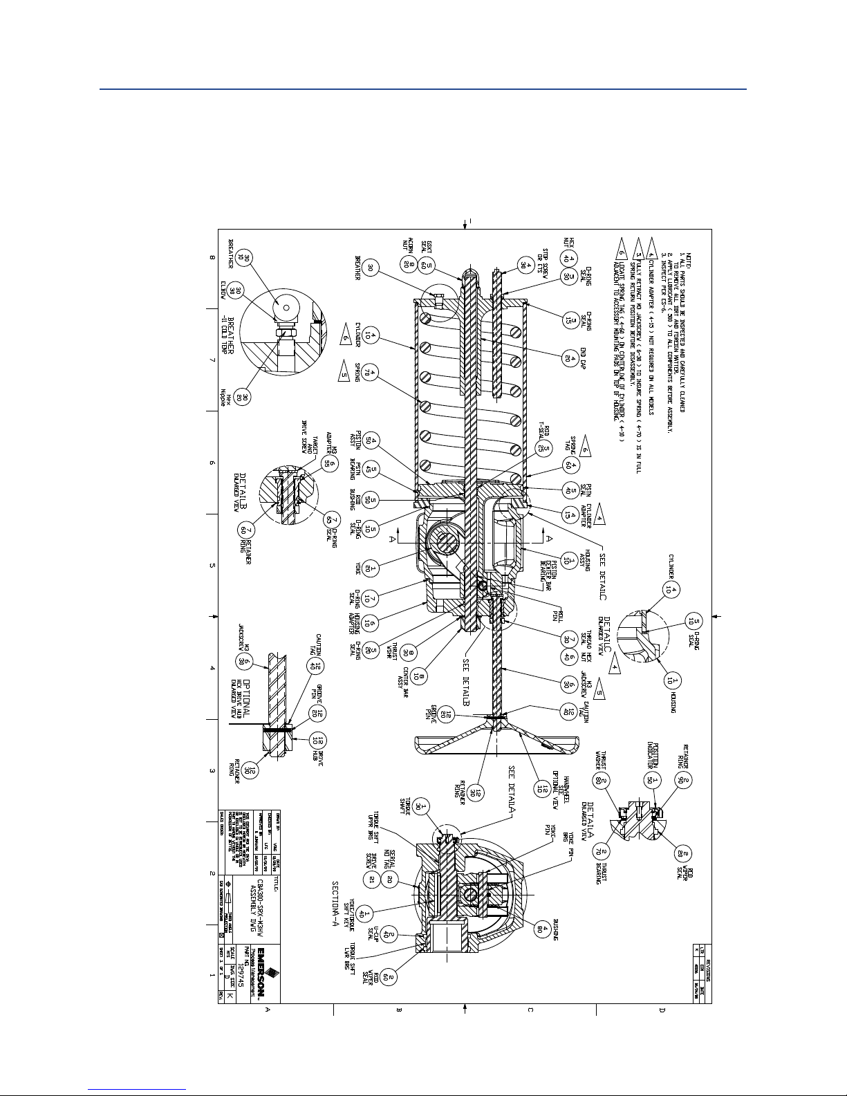
B�2 Part No� 129745, CBA300-SRX-M3HW
Assembly Drawing
Appendix
August 2015
Appendix
25
Page 30

Page 31

World Area Confi guration Centers (WACC) offer sales support, service,
inventory and commissioning to our global customers.
Choose the WACC or sales offi ce nearest you:
NORTH & SOUTH AMERICA
19200 Northwest Freeway
Houston TX 77065
USA
T +1 281 477 4100
Av. Hollingsworth
325 Iporanga Sorocaba
SP 18087-105
Brazil
MIDDLE EAST & AFRICA
P. O. Box 17033
Jebel Ali Free Zone
Dubai
T +971 4 811 8100
P. O. Box 10305
Jubail 31961
Saudi Arabia
T +966 3 340 8650
T +55 15 3413 8888
24 Angus Crescent
ASIA PACIFIC
Longmeadow Business Estate East
P.O. Box 6908 Greenstone
No. 9 Gul Road
#01-02 Singapore 629361
T +65 6777 8211
No. 1 Lai Yuan Road
1616 Modderfontein Extension 5
South Africa
T +27 11 451 3700
EUROPE
Wuqing Development Area
Tianjin 301700
P. R. China
T +86 22 8212 3300
Holland Fasor 6
Székesfehérvár 8000
Hungary
T +36 22 53 09 50
Strada Biffi 165
29017 Fiorenzuola d’Arda (PC)
Italy
T +39 0523 944 411
For complete list of sales and manufacturing sites, please visit
www.emerson.com/actuationtechnologieslocations or contact us at
info.actuationtechnologies@emerson.com
www.emerson.com/bettis
©2018 Emerson. All rights reserved.
The Emerson logo is a trademark and service mark of Emerson Electric Co.
TM
is a mark of one of the Emerson family of companies.
Bettis
All other marks are property of their respective owners.
The contents of this publication are presented for information purposes
only, and while every effort has been made to ensure their accuracy,
they are not to be construed as warranties or guarantees, express or
implied, regarding the products or services described herein or their use
or applicability. All sales are governed by our terms and conditions, which
are available on request. We reserve the right to modify or improve the
designs or specifications of our products at any time without notice.
 Loading...