

Emerson Bettis Q-Series, Bettis QC4124VDC, Bettis QC42115VAC, Bettis QC43230VAC Installation Manual

Installation Guide Bettis Q-Series
DOC.IG.BQC41.1 Rev. 3 August 2018
Bettis Integrated Control Modules
QC41 24VDC
QC42 115VAC
QC43 230VAC
Bettis Q-Series Installation Guide
August 2018 DOC.IG.BQC41.1 Rev. 3
1 Applicable Control modules:
QC41 - 24VDC - Weather Proof
- Explosion Proof / Flame proof
QC42 - 115VAC - Weather Proof
- Explosion Proof / Flame proof
QC43 - 230VAC - Weather Proof
- Explosion Proof / Flame proof
Note:
Both executions can be equipped with one or two
pilot valves:
* One pilot valve is default and suitable for normal
operation of double acting or spring return
actuators.
* Two pilot valves are required for Fail in Last
Position function on double acting actuators.
The enclosures of both Weather Proof and Explosion
Proof / Flame proof modules, have a IP66 or NEMA
4X, ingress protected rating.
2 Before starting
* Actuator must be isolated both pneumatically
and electrically before any (dis)assembly is
begun.
* Installation, adjustment, putting into service,
use, assembly, disassembly and maintenance of
the control module must be done by qualified
personnel.
* Be sure that the actuator is correctly mounted
before connecting air supply and electrical
wiring (see Installation & Operation Manual
Bettis Q-Series Valve Actuator, DOC.IOM.BQ.E)
* Check the module label for the right execution
(see figure 2.2)
* Check the type of actuator: single or double
acting (see figure 2.2).
* For mechanical installation of the module see
installation instruction leaflet DOC.QC4.MTI.1,
as shipped with the module.
2.1 Intended use
The Bettis Q-Series actuator is an integrated
concept for the automation of quarter turn valves,
dampers or other quarter turn applications. It
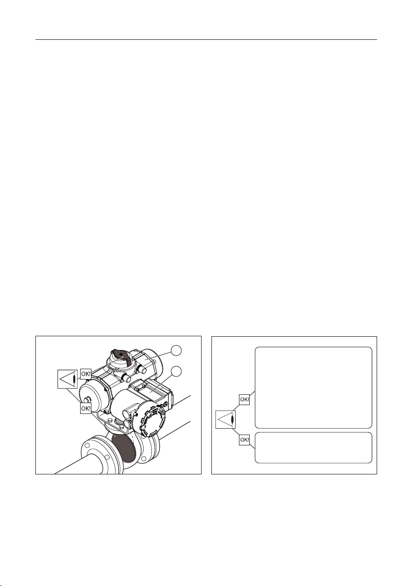
consists of two basic parts (see figure 2.1):
1. Pneumatic actuator
2. Control Module
The control module allows operation of the
actuator and supplies position feedback signals.
1
2
Fig. 2.1 Check proper mounting before connecting air
supply and electrical wiring.
2
Control Module Type Label =
24VDC
QC41..WP.. = Weather Proof
QC41..Px.. = Explosion-/Flame proof
115VAC
QC42..WP.. = Weather Proof
QC42..Px.. = Explosion-/Flame proof
230VAC
QC43..WP.. = Weather Proof
QC43..Px.. = Explosion-/Flame proof
Actuator Type Label =
QS xxxx = Single acting (Spring Return)
QD xxxx = Double acting
Fig. 2.2 Identification
Installation Guide Bettis Q-Series
DOC.IG.BQC41.1 Rev. 3 August 2018
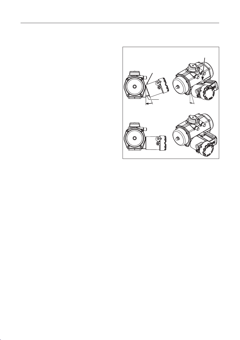
2.2 Mechanical alignment and mounting of
the control module
The control module is equipped with an alignmentedge on top of the module. This allows easy
alignment and mounting of the control module on
to the actuator housing.
Procedure: (see figure 2.3)
1. First take care that both mating faces from the
actuator and control module are clean and free
of dirt.
2. Check if the module has the required function
3. Remove the transparent film from the control
module.
4. Ensure seals are placed correctly.
5. Level the screws with the surface.
6. Place the alignment-edge (1) of the control
module at the top of the pneumatic interface.
7. Flip the module down taking care that the IPT
Probe (see fig 5; nr.2) on the actuator fits in the
mating hole on the control module and loosely
place the screws.
8. Tighten screws according force in sequence.
Tightening moments
The Control Module should be fastened by using
an Allen key and applying the following tightening
moments:
- Allen Key No 5: 6.1 to 6.6 Nm (54 - 58.4
In.lbs)
Alignment-edge
Alignment-edge
IPT probe
Fig. 2.3 Alignment and mounting of control
module to actuator
3
Bettis Q-Series Installation Guide
August 2018 DOC.IG.BQC41.1 Rev. 3
3 Pneumatic connections
IMPORTANT
1 The actuator/valve combination can move
after connecting the air supply.
2 Ensure that the QC4x control modules are
mounted properly to the actuator to achieve
good functioning and the required ingress
protection, before connecting the air supply.
3 Check that the maximum supply pressure
P
= 8bar/116Psi
max
4 Be sure that the minimum required supply
pressure for the application is available at the
actuator.
5 Take appropriate measures to prevent
condensation or moisture to entering the
actuator or the control module. Condensation
or moisture can damage these components
and can result in failures.
6 The exhaust ports Ra and Rb on the module
(see figure 3.1) are shipped from the factory
with transport protection.
* If ingress protection IP66 or NEMA 4X is
required, appropriate connections must be
used in exhaust ports Ra & Rb.
3.1 Operating media :
* Air or inert gasses.
* Air filtered at 50 micron.
* Dew point 10 K below operating temperature.
* For subzero applications take appropriate
measures.
3.2 Single acting (spring return) or Double
acting actuator :
1 Remove the transport sticker from the air supply
(Ps).
2 Connect air supply to port (Ps).
Single acting
Control
Module cover
Double acting
Fig. 3.1 Pneumatic connections
Ra
Ps
1/4” BSP or
1/4” NPT
Ra
Rb
Ps
1/4” BSP or
1/4” NPT
4

Installation Guide Bettis Q-Series
DOC.IG.BQC41.1 Rev. 3 August 2018
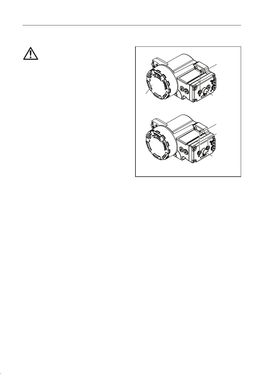
4 Electric Connections
The conventional Control Module contains a pilot
valve for controlling the actuator and switches for
position feedback.
WARNING:
* If the Control Module is used in a manner not
specified by the manufacturer, the protection
provided by the equipment may be impaired.
* For electrical safety the marked protective
conductor terminal inside or outside the
Control Module housing shall be connected to
earth.
* If required, mount earth wire (1) between top
(2) and stainless steel washer (3) of earth wire
connection (see figure 4.2).
* To fulfill the electrical safety regulations
according IEC 61010-1, a switch and circuitbreaker shall be included in the building
installation. It is advised to indicate the
location of the circuit breaker by means of a
label on or nearby the installed
Bettis Q-Series modules. The disconnection
switch or circuit breaker shall disconnect all
current-carrying conductors.
* Heat resistant cable and cable glands shall be
used, suitable for temperatures of at least 80°C
* Use and mount cable glands as required by
national or local legislation.
* If IP66 or NEMA 4X ingress protection is
required, then the electrical entries must be
fitted with devices rated IP66 or NEMA 4X.
Electrical safety requirements:
Use In- and outdoor.
Altitude
Maximum relative humidity
Mains supply
fluctuation
Over voltage
category
Pollution degree 2 (3 when the cover remains closed)
Temperature see table 4.1
Operating full power available
up to 2000 meter (6000 feet).
80% for temperatures up to 31°C
(87.8°F) decreasing linearly to
50% relative humidity at 40°C
(104°F).
up to ±10% of nominal voltage
II
Caution! :
Risk of electric shock
* Installation, adjustment, putting into service,
use, assembly, disassembly and maintenance
of the control module is strictly reserved to
qualified personnel.
* Do not attempt to install or repair any electric
device without shutting off incoming power.
Terminals
Lockable
Module cover
Electrical entries:
3/4”NPT
or M25
1/2”NPT
or M20
Switch terminals
Control Module
Type Label
Pilot valve
terminals
Option: Manual
control
Option: Additional
manual control for
“Fail in Last Position”
Fig. 4.1 Terminal connections behind cover.
Fig. 4.2 Earth wire connection
5
Bettis Q-Series Installation Guide
August 2018 DOC.IG.BQC41.1 Rev. 3
4.1 Bettis Q-Series QC4x modules
Hazardous Area instructions
IMPORTANT
All installation, inspection, maintenance and
repair of the equipment should be performed
by suitably trained personnel.
The Control Modules must not be used in
atmospheres that contains acetone, ethyl
acetate or acetic acid vapors.
4.1.1 ATEX/IECEx Intended use
The Control Modules QC4x..P5.. of the
Bettis Q-Series pneumatic actuator is a Group II
category 2 (ATEX) equipment with protection level
Gb, Db (IECEx) and intended for use in areas in
which explosive atmospheres caused by mixtures of
air and gases, vapors, mists or by air/dusts are likely
to occur.
The pneumatic actuator part, together with the
pneumatic module part of the Bettis Q-Series
pneumatic actuators is a Group II category 2
equipment and intended for use in areas in which
explosive atmospheres caused by mixtures of air
and gases, vapors, mists or by air/dusts are likely to
occur.
Therefore it may be used in hazardous area
classified Zones 1, 2 (Gasses) and/or 21, 22 (Dust).
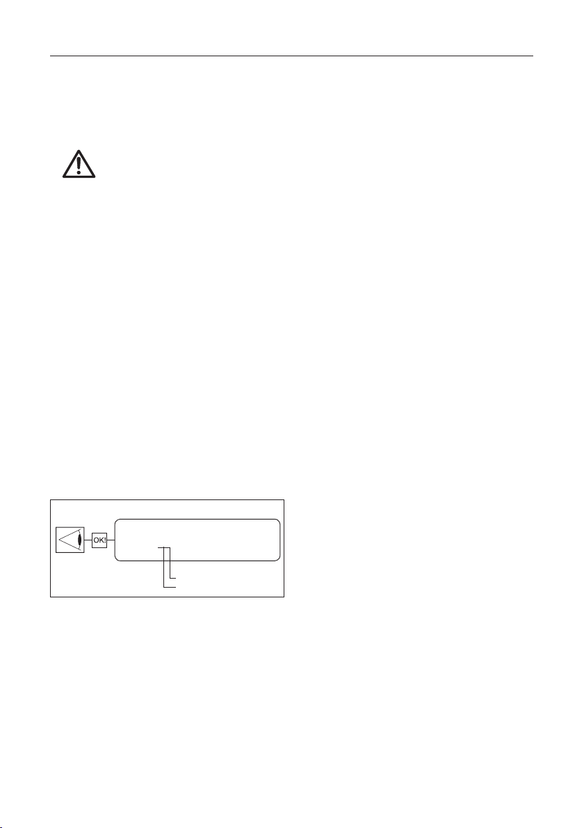
Control Module Type Label =
QC41·MP5MSA1·0040UQP000
Pneumatic action
Switch cartridge
Fig. 4.4 Switch cartridge and pneumatic action
identification
4.1.2 Hazardous area Special safety instructions
for safe use
1. For ATEX, all installation, inspection,
maintenance and repair must be done by
suitably trained personnel. For information refer
to EN60079-14, EN60079-17, EN60079-19.
2. Substitution of component may impair
suitability for Zone 2 Increased Safety.
3. Do not open cover of terminal compartment
when an explosive atmosphere is present.
4. Cleaning this housing by rubbing should be done
in a non-hazardous area,
5. Potential electrostatic charging hazard, clean
only with a damp cloth - danger of propagating
discharge.
6. The apparatus shall be installed in such a way
that the risk from electrostatic discharges and
propagating brush discharges caused by rapid
flow of dust is avoided.
7. All grounding and bonding installation
requirements must be addressed.
8. The cable entry device and the closing elements
of unused apertures must be of a certified
flameproof type, suitable for the conditions of
use and correctly installed.
9 Blind plugs or cable gland shall be engaged
into the cable entries minimal 5.5 threads for
M20x1.5 entries and minimal 5 threads for NPT
entries.
10. Certified Ex t cable glands shall be use in a dust
environment.
11. Heat resistant cable and cable glands shall be
used, suitable for temperatures of at least 80°C
12. The maximum temperature of the supply
air must stay below the maximum ambient
temperature as marked on the control module
(see table 4.1).
13. The maximum temperature of the base actuator
must stay below the maximum ambient
temperature as marked on the control module
(see table 4.1).
14. Contact your local Emerson representative for
information on the dimensions of the flame
proof joints.
15.Precaution shall be taken to avoid danger of
ignition due to electrostatic charges on the
marking plate of the enclosure.
4.1.3 FM Special safety instructions
1. Metric entries are not allowed. Metric entries are
for IECEx or ATEX installations only.
2. Wiring must be done according NEC 500.
Note:
This product is only intended for use in large-scale
fixed installations excluded from the scope of
Directive 2011/65/EU on the restriction of the use
of certain hazardous substances in electrical and
electronic equipment (RoHS 2).
6
 Loading...