

Page 1

AXP1406/AXP1600 Subsystem IPMI
Programmer’s Reference
6806800B66C
April 2008
Page 2

©
Copyright 2008 Emerson
All rights reserved.
Trademarks
Emerson, Business-Critical Continuity, Emerson Network Power and the Emerson Network Power logo are trademarks and service
marks of Emerson Electric Co.
All other trademarks are the property of their respective owners.
®
is a trademark or registered trademark of Intel Corporation or its subsidiaries in the United States and other countries.
Intel
®
PICMG
PCI Industrial Computer Manufacturers Group.
, CompactPCI®, AdvancedTCA™ and the PICMG, CompactPCI and AdvancedTCA logos are registered trademarks of the
©
2008 Emerson Electric Co.
Notice
While reasonable efforts have been made to assure the accuracy of this document, Emerson assumes no liability resulting from any
omissions in this document, or from the use of the information obtained therein. Emerson reserves the right to revise this document
and to make changes from time to time in the content hereof without obligation of Emerson to notify any person of such revision or
changes.
Electronic versions of this material may be read online, downloaded for personal use, or referenced in another document as a URL to
a Emerson website. The text itself may not be published commercially in print or electronic form, edited, translated, or otherwise altered
without the permission of Emerson,
It is possible that this publication may contain reference to or information about Emerson products (machines and programs),
programming, or services that are not available in your country. Such references or information must not be construed to mean that
Emerson intends to announce such Emerson products, programming, or services in your country.
Limited and Restricted Rights Legend
If the documentation contained herein is supplied, directly or indirectly, to the U.S. Government, the following notice shall apply unless
otherwise agreed to in writing by Emerson.
Use, duplication, or disclosure by the Government is subject to restrictions as set forth in subparagraph (b)(3) of the Rights in Technical
Data clause at DFARS 252.227-7013 (Nov. 1995) and of the Rights in Noncommercial Computer Software and Documentation clause
at DFARS 252.227-7014 (Jun. 1995).
Contact Address
Emerson Network Power - Embedded Computing
2900 South Diablo Way, Suite 190
Tempe, AZ 85282
USA
Page 3

Contents
About this Manual . . . . . . . . . . . . . . . . . . . . . . . . . . . . . . . . . . . . . . . . . . . . . . . . . . . . . . . . . . . . . . . . . . 11
1 Supported IPMI Commands . . . . . . . . . . . . . . . . . . . . . . . . . . . . . . . . . . . . . . . . . . . . . . . . . . . . . . . 15
1.1 Introduction . . . . . . . . . . . . . . . . . . . . . . . . . . . . . . . . . . . . . . . . . . . . . . . . . . . . . . . . . . . . . . . . 15
1.2 Standard IPMI Commands . . . . . . . . . . . . . . . . . . . . . . . . . . . . . . . . . . . . . . . . . . . . . . . . . . . . 15
1.2.1 Global IPMI Commands . . . . . . . . . . . . . . . . . . . . . . . . . . . . . . . . . . . . . . . . . . . . . . . . . 15
1.2.2 BMC WatchDog Timer Commands . . . . . . . . . . . . . . . . . . . . . . . . . . . . . . . . . . . . . . . . 16
1.2.3 BMC Device and Messaging Commands. . . . . . . . . . . . . . . . . . . . . . . . . . . . . . . . . . . . 16
1.2.4 Chassis Device Commands . . . . . . . . . . . . . . . . . . . . . . . . . . . . . . . . . . . . . . . . . . . . . . 17
1.2.5 Event Commands . . . . . . . . . . . . . . . . . . . . . . . . . . . . . . . . . . . . . . . . . . . . . . . . . . . . . . 17
1.2.6 PEF and Alerting Commands . . . . . . . . . . . . . . . . . . . . . . . . . . . . . . . . . . . . . . . . . . . . . 17
1.2.7 Sensor Device Commands. . . . . . . . . . . . . . . . . . . . . . . . . . . . . . . . . . . . . . . . . . . . . . . 18
1.2.8 FRU Device Commands. . . . . . . . . . . . . . . . . . . . . . . . . . . . . . . . . . . . . . . . . . . . . . . . . 19
1.2.9 SDR Device Commands . . . . . . . . . . . . . . . . . . . . . . . . . . . . . . . . . . . . . . . . . . . . . . . . 19
1.2.10 SEL Device Commands . . . . . . . . . . . . . . . . . . . . . . . . . . . . . . . . . . . . . . . . . . . . . . . . . 19
1.2.11 LAN Device Commands . . . . . . . . . . . . . . . . . . . . . . . . . . . . . . . . . . . . . . . . . . . . . . . . . 20
1.2.12 Serial/Modem Device Commands . . . . . . . . . . . . . . . . . . . . . . . . . . . . . . . . . . . . . . . . . 20
1.3 PICMG 3.0 Commands . . . . . . . . . . . . . . . . . . . . . . . . . . . . . . . . . . . . . . . . . . . . . . . . . . . . . . . 21
1.4 Emerson and Pigeon Point OEM Commands . . . . . . . . . . . . . . . . . . . . . . . . . . . . . . . . . . . . . . 22
2 FRU Information and Sensor Data Records . . . . . . . . . . . . . . . . . . . . . . . . . . . . . . . . . . . . . . . . . . 25
2.1 Introduction . . . . . . . . . . . . . . . . . . . . . . . . . . . . . . . . . . . . . . . . . . . . . . . . . . . . . . . . . . . . . . . . 25
2.2 Total Power Consumption . . . . . . . . . . . . . . . . . . . . . . . . . . . . . . . . . . . . . . . . . . . . . . . . . . . . . 25
2.3 SAM1000 Physical Shelf Manager . . . . . . . . . . . . . . . . . . . . . . . . . . . . . . . . . . . . . . . . . . . . . . 26
2.3.1 SAM Physical FRU Information . . . . . . . . . . . . . . . . . . . . . . . . . . . . . . . . . . . . . . . . . . . 26
2.3.1.1 Physical Shelf Manager FRU Data, AXP1406 . . . . . . . . . . . . . . . . . . . . . . . . 26
2.3.1.2 Physical Shelf Manager FRU Data, AXP1600 . . . . . . . . . . . . . . . . . . . . . . . . 27
2.3.2 E-Keying. . . . . . . . . . . . . . . . . . . . . . . . . . . . . . . . . . . . . . . . . . . . . . . . . . . . . . . . . . . . . 28
2.3.3 Power Configuration . . . . . . . . . . . . . . . . . . . . . . . . . . . . . . . . . . . . . . . . . . . . . . . . . . . . 28
2.3.4 Sensor Overview . . . . . . . . . . . . . . . . . . . . . . . . . . . . . . . . . . . . . . . . . . . . . . . . . . . . . . 29
2.3.5 SAM Physical Shelf Manager Analog Sensors . . . . . . . . . . . . . . . . . . . . . . . . . . . . . . . 30
2.3.5.1 Voltage Sensors . . . . . . . . . . . . . . . . . . . . . . . . . . . . . . . . . . . . . . . . . . . . . . . 30
2.3.5.2 Temperature Sensors . . . . . . . . . . . . . . . . . . . . . . . . . . . . . . . . . . . . . . . . . . . 32
2.3.6 SAM Module Discrete Sensors . . . . . . . . . . . . . . . . . . . . . . . . . . . . . . . . . . . . . . . . . . . 34
2.3.6.1 Hot Swap Sensor . . . . . . . . . . . . . . . . . . . . . . . . . . . . . . . . . . . . . . . . . . . . . . 35
2.3.6.2 IPMB Link Sensor . . . . . . . . . . . . . . . . . . . . . . . . . . . . . . . . . . . . . . . . . . . . . . 35
2.3.6.3 PEM A Sensor . . . . . . . . . . . . . . . . . . . . . . . . . . . . . . . . . . . . . . . . . . . . . . . . 36
2.3.6.4 PEM B Sensor . . . . . . . . . . . . . . . . . . . . . . . . . . . . . . . . . . . . . . . . . . . . . . . . 37
2.3.6.5 AXP Backplane ID Sensor . . . . . . . . . . . . . . . . . . . . . . . . . . . . . . . . . . . . . . . 39
AXP1406/AXP1600 Subsystem IPMI Programmer’s Reference (6806800B66C)
3
Page 4

Contents
2.3.6.6 +12 V B Valid Sensor . . . . . . . . . . . . . . . . . . . . . . . . . . . . . . . . . . . . . . . . . . . 39
2.3.6.7 +12 V A Valid Sensor . . . . . . . . . . . . . . . . . . . . . . . . . . . . . . . . . . . . . . . . . . 40
2.3.6.8 Fault Event Sensor . . . . . . . . . . . . . . . . . . . . . . . . . . . . . . . . . . . . . . . . . . . . . 41
2.3.6.9 POST Results Sensor . . . . . . . . . . . . . . . . . . . . . . . . . . . . . . . . . . . . . . . . . . 41
2.3.6.10 Shelf FRU Info Sensor . . . . . . . . . . . . . . . . . . . . . . . . . . . . . . . . . . . . . . . . . . 42
2.3.6.11 CPLD State Sensor . . . . . . . . . . . . . . . . . . . . . . . . . . . . . . . . . . . . . . . . . . . . 43
2.4 SAM1000 Active (Virtual) Shelf Manager . . . . . . . . . . . . . . . . . . . . . . . . . . . . . . . . . . . . . . . . . 43
2.4.1 FRU Information . . . . . . . . . . . . . . . . . . . . . . . . . . . . . . . . . . . . . . . . . . . . . . . . . . . . . . . 43
2.4.1.1 Active Shelf Manager FRU Data, AXP1406 . . . . . . . . . . . . . . . . . . . . . . . . . . 44
2.4.1.2 Active Shelf Manager FRU Data, AXP1600 . . . . . . . . . . . . . . . . . . . . . . . . . . 46
2.4.1.3 SAM1000 Shelf Manager FRU Data . . . . . . . . . . . . . . . . . . . . . . . . . . . . . . . 48
2.4.1.4 Fan Tray FRU Data, AXP1406 . . . . . . . . . . . . . . . . . . . . . . . . . . . . . . . . . . . . 49
2.4.1.5 Fan Tray FRUs 1,2, and 3 Data . . . . . . . . . . . . . . . . . . . . . . . . . . . . . . . . . . . 50
2.4.1.6 Fan Tray FRUs 4, 5, and 6 Data . . . . . . . . . . . . . . . . . . . . . . . . . . . . . . . . . . 51
2.4.1.7 Fan Tray FRUs 7 and 8 Data . . . . . . . . . . . . . . . . . . . . . . . . . . . . . . . . . . . . . 51
2.4.1.8 Fan Tray FRU Data, AXP1600 . . . . . . . . . . . . . . . . . . . . . . . . . . . . . . . . . . . . 52
2.4.1.9 Fan Tray FRUs 1, 2, and 3 Data, AXP1600 . . . . . . . . . . . . . . . . . . . . . . . . . . 53
2.4.1.10 Fan Tray FRUs 4, 5, and 6 Data, AXP1600 . . . . . . . . . . . . . . . . . . . . . . . . . . 54
2.4.1.11 Fan Tray FRUs 7, 8 and 9 Data, AXP1600 . . . . . . . . . . . . . . . . . . . . . . . . . . 55
2.4.2 E-Keying. . . . . . . . . . . . . . . . . . . . . . . . . . . . . . . . . . . . . . . . . . . . . . . . . . . . . . . . . . . . . 55
2.4.3 Power Configuration . . . . . . . . . . . . . . . . . . . . . . . . . . . . . . . . . . . . . . . . . . . . . . . . . . . . 56
2.4.4 Active SAM1000 Sensor Overview . . . . . . . . . . . . . . . . . . . . . . . . . . . . . . . . . . . . . . . . 56
2.4.5 Active SAM1000 Analog Sensors . . . . . . . . . . . . . . . . . . . . . . . . . . . . . . . . . . . . . . . . . 61
2.4.5.1 Fan Speed Sensors . . . . . . . . . . . . . . . . . . . . . . . . . . . . . . . . . . . . . . . . . . . . 61
2.4.5.2 Fan Voltage Sensors . . . . . . . . . . . . . . . . . . . . . . . . . . . . . . . . . . . . . . . . . . . 70
2.4.6 SAM Active Shelf Manager Discrete Sensors . . . . . . . . . . . . . . . . . . . . . . . . . . . . . . . . 92
2.4.6.1 Hot Swap Sensors . . . . . . . . . . . . . . . . . . . . . . . . . . . . . . . . . . . . . . . . . . . . . 93
2.4.6.2 Shm Fault Event Sensor . . . . . . . . . . . . . . . . . . . . . . . . . . . . . . . . . . . . . . . . 98
2.4.6.3 IPMB Link Sensor . . . . . . . . . . . . . . . . . . . . . . . . . . . . . . . . . . . . . . . . . . . . . . 99
2.4.6.4 Telco Alarm Sensor . . . . . . . . . . . . . . . . . . . . . . . . . . . . . . . . . . . . . . . . . . . . 112
2.4.6.5 BMC Watchdog Sensor . . . . . . . . . . . . . . . . . . . . . . . . . . . . . . . . . . . . . . . . 113
2.4.6.6 System Event . . . . . . . . . . . . . . . . . . . . . . . . . . . . . . . . . . . . . . . . . . . . . . . . 113
2.4.6.7 Fan Tray Presence Sensor . . . . . . . . . . . . . . . . . . . . . . . . . . . . . . . . . . . . . 114
2.4.6.8 Fan Tray -48 V Fuse Sensor . . . . . . . . . . . . . . . . . . . . . . . . . . . . . . . . . . . . 119
2.5 Power Entry Module Sensor Data Records . . . . . . . . . . . . . . . . . . . . . . . . . . . . . . . . . . . . . . 124
2.5.1 PEM FRU Information . . . . . . . . . . . . . . . . . . . . . . . . . . . . . . . . . . . . . . . . . . . . . . . . . 124
2.5.2 E-Keying. . . . . . . . . . . . . . . . . . . . . . . . . . . . . . . . . . . . . . . . . . . . . . . . . . . . . . . . . . . . 125
2.5.3 Power Configuration . . . . . . . . . . . . . . . . . . . . . . . . . . . . . . . . . . . . . . . . . . . . . . . . . . . 125
2.5.4 Power Entry Module Sensor Overview. . . . . . . . . . . . . . . . . . . . . . . . . . . . . . . . . . . . . 126
2.5.5 Power Entry Module Analog Sensors. . . . . . . . . . . . . . . . . . . . . . . . . . . . . . . . . . . . . . 126
2.5.5.1 Voltage Sensors . . . . . . . . . . . . . . . . . . . . . . . . . . . . . . . . . . . . . . . . . . . . . . 127
2.5.5.2 Current Sensor . . . . . . . . . . . . . . . . . . . . . . . . . . . . . . . . . . . . . . . . . . . . . . . 131
2.5.5.3 Temperature Sensor . . . . . . . . . . . . . . . . . . . . . . . . . . . . . . . . . . . . . . . . . . 132
2.5.6 Power Entry Module Discrete Sensors. . . . . . . . . . . . . . . . . . . . . . . . . . . . . . . . . . . . . 132
2.5.6.1 Hot Swap Sensor . . . . . . . . . . . . . . . . . . . . . . . . . . . . . . . . . . . . . . . . . . . . . 132
2.5.6.2 IPMB Link Sensor . . . . . . . . . . . . . . . . . . . . . . . . . . . . . . . . . . . . . . . . . . . . . 133
4
AXP1406/AXP1600 Subsystem IPMI Programmer’s Reference (6806800B66C)
Page 5

Contents
2.5.7 Circuit Breaker State Sensors . . . . . . . . . . . . . . . . . . . . . . . . . . . . . . . . . . . . . . . . . . . 134
3 OEM Sensors. . . . . . . . . . . . . . . . . . . . . . . . . . . . . . . . . . . . . . . . . . . . . . . . . . . . . . . . . . . . . . . . . . 137
3.1 OEM Sensors . . . . . . . . . . . . . . . . . . . . . . . . . . . . . . . . . . . . . . . . . . . . . . . . . . . . . . . . . . . . . 137
3.1.1 Telco Alarms (Pigeon Point OEM) . . . . . . . . . . . . . . . . . . . . . . . . . . . . . . . . . . . . . . . . 137
3.1.2 AXP Backplane ID (Emerson OEM). . . . . . . . . . . . . . . . . . . . . . . . . . . . . . . . . . . . . . . 138
3.1.3 POST Results (Emerson OEM) . . . . . . . . . . . . . . . . . . . . . . . . . . . . . . . . . . . . . . . . . . 138
3.1.4 Shelf FRU Info (Emerson OEM). . . . . . . . . . . . . . . . . . . . . . . . . . . . . . . . . . . . . . . . . . 139
3.1.5 FT -48 V Fuse (Emerson OEM) . . . . . . . . . . . . . . . . . . . . . . . . . . . . . . . . . . . . . . . . . . 139
3.1.6 Shm Fault Event (Emerson OEM) . . . . . . . . . . . . . . . . . . . . . . . . . . . . . . . . . . . . . . . . 140
A System Behavior in Response to Sensor Events . . . . . . . . . . . . . . . . . . . . . . . . . . . . . . . . . . . . 141
A.1 Introduction . . . . . . . . . . . . . . . . . . . . . . . . . . . . . . . . . . . . . . . . . . . . . . . . . . . . . . . . . . . . . . . 141
A.2 Cooling Management in Normal Operation Mode . . . . . . . . . . . . . . . . . . . . . . . . . . . . . . . . . 141
A.3 Cooling Management in Abnormal Operation Mode . . . . . . . . . . . . . . . . . . . . . . . . . . . . . . . . 141
A.4 Adaptive Adjustment of the Minimum Fan Level . . . . . . . . . . . . . . . . . . . . . . . . . . . . . . . . . . . 142
A.5 FRU State Management . . . . . . . . . . . . . . . . . . . . . . . . . . . . . . . . . . . . . . . . . . . . . . . . . . . . . 144
B Related Documentation . . . . . . . . . . . . . . . . . . . . . . . . . . . . . . . . . . . . . . . . . . . . . . . . . . . . . . . . . 147
B.1 Emerson Network Power - Embedded Computing Documents . . . . . . . . . . . . . . . . . . . . . . . 147
B.2 Manufacturers’ Documents . . . . . . . . . . . . . . . . . . . . . . . . . . . . . . . . . . . . . . . . . . . . . . . . . . . 148
B.3 Related Specifications . . . . . . . . . . . . . . . . . . . . . . . . . . . . . . . . . . . . . . . . . . . . . . . . . . . . . . 148
AXP1406/AXP1600 Subsystem IPMI Programmer’s Reference (6806800B66C)
5
Page 6

Contents
6
AXP1406/AXP1600 Subsystem IPMI Programmer’s Reference (6806800B66C)
Page 7

List of Tables
Table 1-1 Supported Global IPMI Commands . . . . . . . . . . . . . . . . . . . . . . . . . . . . . . . . . . . . . . . 15
Table 1-2 Supported BMC WatchDog Timer Commands . . . . . . . . . . . . . . . . . . . . . . . . . . . . . . 16
Table 1-3 Supported BMC Device and Messaging Commands . . . . . . . . . . . . . . . . . . . . . . . . . . 16
Table 1-4 Supported Chassis Device Commands . . . . . . . . . . . . . . . . . . . . . . . . . . . . . . . . . . . . 17
Table 1-5 Supported Event Commands . . . . . . . . . . . . . . . . . . . . . . . . . . . . . . . . . . . . . . . . . . . . 17
Table 1-6 Supported PEF and Alerting Commands . . . . . . . . . . . . . . . . . . . . . . . . . . . . . . . . . . . 17
Table 1-7 Supported Sensor Device Commands . . . . . . . . . . . . . . . . . . . . . . . . . . . . . . . . . . . . . 18
Table 1-8 Supported FRU Commands . . . . . . . . . . . . . . . . . . . . . . . . . . . . . . . . . . . . . . . . . . . . . 19
Table 1-9 Supported SDR Device Commands . . . . . . . . . . . . . . . . . . . . . . . . . . . . . . . . . . . . . . . 19
Table 1-10 Supported SEL Commands . . . . . . . . . . . . . . . . . . . . . . . . . . . . . . . . . . . . . . . . . . . . . 19
Table 1-11 Supported LAN Device Commands . . . . . . . . . . . . . . . . . . . . . . . . . . . . . . . . . . . . . . . 20
Table 1-12 Supported Serial/Modem Device Commands . . . . . . . . . . . . . . . . . . . . . . . . . . . . . . . 20
Table 1-13 Supported PICMG 3.0 Commands . . . . . . . . . . . . . . . . . . . . . . . . . . . . . . . . . . . . . . . 21
Table 1-14 OEM Command Summary . . . . . . . . . . . . . . . . . . . . . . . . . . . . . . . . . . . . . . . . . . . . . . 22
Table 1-15 Get Shelf Configuration Record (Cmd = 0x01) . . . . . . . . . . . . . . . . . . . . . . . . . . . . . . 22
Table 1-16 Shelf Manager Switchover (Cmd = 0x02) . . . . . . . . . . . . . . . . . . . . . . . . . . . . . . . . . . . 23
Table 1-17 Set FRU Extracted (Cmd = 0x03) . . . . . . . . . . . . . . . . . . . . . . . . . . . . . . . . . . . . . . . . . 23
Table 2-1 Total Power Consumption for AXP 1406 and AXP1600 Shelves . . . . . . . . . . . . . . . . . 25
Table 2-2 SAM Physical Power Configuration . . . . . . . . . . . . . . . . . . . . . . . . . . . . . . . . . . . . . . . 28
Table 2-3 Sensor Overview . . . . . . . . . . . . . . . . . . . . . . . . . . . . . . . . . . . . . . . . . . . . . . . . . . . . . 29
Table 2-4 Sensor No. 2 Vbat . . . . . . . . . . . . . . . . . . . . . . . . . . . . . . . . . . . . . . . . . . . . . . . . . . . . 30
Table 2-5 Sensor No. 3 3.3 V Voltage . . . . . . . . . . . . . . . . . . . . . . . . . . . . . . . . . . . . . . . . . . . . . 31
Table 2-6 Sensor No. 4 +12 V Voltage . . . . . . . . . . . . . . . . . . . . . . . . . . . . . . . . . . . . . . . . . . . . . 31
Table 2-7 Sensor No. 5 +1.8 V . . . . . . . . . . . . . . . . . . . . . . . . . . . . . . . . . . . . . . . . . . . . . . . . . . . 32
Table 2-8 Sensor No. 6 MAX6656 INT@1A . . . . . . . . . . . . . . . . . . . . . . . . . . . . . . . . . . . . . . . . . 32
Table 2-9 Sensor No. 7 MAX6656 EXT1@1A . . . . . . . . . . . . . . . . . . . . . . . . . . . . . . . . . . . . . . . 33
Table 2-10 Sensor No. 8 MAX6656 EXT2@1A . . . . . . . . . . . . . . . . . . . . . . . . . . . . . . . . . . . . . . . 34
Table 2-11 Sensor No. 0 FRU 0 HOT_SWAP . . . . . . . . . . . . . . . . . . . . . . . . . . . . . . . . . . . . . . . . 35
Table 2-12 Sensor No. 1 IPMB Link . . . . . . . . . . . . . . . . . . . . . . . . . . . . . . . . . . . . . . . . . . . . . . . . 35
Table 2-13 Sensor No. 9 PEM A . . . . . . . . . . . . . . . . . . . . . . . . . . . . . . . . . . . . . . . . . . . . . . . . . . 36
Table 2-14 Sensor No. 10 PEM B . . . . . . . . . . . . . . . . . . . . . . . . . . . . . . . . . . . . . . . . . . . . . . . . . 37
Table 2-15 Sensor No. 11 NSC A (AXP1600 Only) . . . . . . . . . . . . . . . . . . . . . . . . . . . . . . . . . . . . 37
Table 2-16 Sensor No. 12 NSC B (AXP1600 Only) . . . . . . . . . . . . . . . . . . . . . . . . . . . . . . . . . . . . 38
Table 2-17 Sensor No. 13 AXP Backplane ID . . . . . . . . . . . . . . . . . . . . . . . . . . . . . . . . . . . . . . . . 39
Table 2-18 Sensor No. 14 12 V B Valid . . . . . . . . . . . . . . . . . . . . . . . . . . . . . . . . . . . . . . . . . . . . . 39
Table 2-19 Sensor No. 15 12 V A Valid . . . . . . . . . . . . . . . . . . . . . . . . . . . . . . . . . . . . . . . . . . . . . 40
Table 2-20 Sensor No. 16 Fault Event . . . . . . . . . . . . . . . . . . . . . . . . . . . . . . . . . . . . . . . . . . . . . . 41
Table 2-21 Sensor No. 17 POST Results . . . . . . . . . . . . . . . . . . . . . . . . . . . . . . . . . . . . . . . . . . . . 41
Table 2-22 Sensor No. 18 Shelf FRU Info . . . . . . . . . . . . . . . . . . . . . . . . . . . . . . . . . . . . . . . . . . . 42
Table 2-23 Sensor No. 128 CPLD State . . . . . . . . . . . . . . . . . . . . . . . . . . . . . . . . . . . . . . . . . . . . 43
AXP1406/AXP1600 Subsystem IPMI Programmer’s Reference (6806800B66C)
7
Page 8

List of Tables
Table 2-24 SAM1000 Active Power Configuration . . . . . . . . . . . . . . . . . . . . . . . . . . . . . . . . . . . . . 56
Table 2-25 Active SAM1000 Sensor Overview . . . . . . . . . . . . . . . . . . . . . . . . . . . . . . . . . . . . . . . 56
Table 2-26 Sensor No. 141 (0x8D) FT 1 Fan 1 . . . . . . . . . . . . . . . . . . . . . . . . . . . . . . . . . . . . . . . 61
Table 2-27 Sensor No. 142 (0x8E) FT 1 Fan 2 . . . . . . . . . . . . . . . . . . . . . . . . . . . . . . . . . . . . . . . 61
Table 2-28 Sensor No. 143 (0x8F) FT 2 Fan 1 . . . . . . . . . . . . . . . . . . . . . . . . . . . . . . . . . . . . . . . . 62
Table 2-29 Sensor No. 144 (0x90) FT2 Fan 2 . . . . . . . . . . . . . . . . . . . . . . . . . . . . . . . . . . . . . . . . 62
Table 2-30 Sensor No. 145 (0x91) FT 3 Fan 1 . . . . . . . . . . . . . . . . . . . . . . . . . . . . . . . . . . . . . . . . 63
Table 2-31 Sensor No. 146 (0x92) FT 3 Fan 2 . . . . . . . . . . . . . . . . . . . . . . . . . . . . . . . . . . . . . . . . 63
Table 2-32 Sensor No. 147 (0x93) FT 4 Fan 1 . . . . . . . . . . . . . . . . . . . . . . . . . . . . . . . . . . . . . . . . 64
Table 2-33 Sensor No. 148 (0x94) FT 4 Fan 2 . . . . . . . . . . . . . . . . . . . . . . . . . . . . . . . . . . . . . . . . 64
Table 2-34 Sensor No. 149 (0x95) FT 5 Fan 1 . . . . . . . . . . . . . . . . . . . . . . . . . . . . . . . . . . . . . . . . 65
Table 2-35 Sensor No. 150 (0x96) FT 5 Fan 2 . . . . . . . . . . . . . . . . . . . . . . . . . . . . . . . . . . . . . . . . 65
Table 2-36 Sensor No. 151 (0x97) FT 6 Fan 1 . . . . . . . . . . . . . . . . . . . . . . . . . . . . . . . . . . . . . . . . 66
Table 2-37 Sensor No. 152 (0x98) FT 6 Fan 2 . . . . . . . . . . . . . . . . . . . . . . . . . . . . . . . . . . . . . . . . 66
Table 2-38 Sensor No. 153 (0x99) FT 7 Fan 1 . . . . . . . . . . . . . . . . . . . . . . . . . . . . . . . . . . . . . . . . 67
Table 2-39 Sensor No. 154 (0x9A) FT 7 Fan 2 . . . . . . . . . . . . . . . . . . . . . . . . . . . . . . . . . . . . . . . 67
Table 2-40 Sensor No. 155 (0x9B) FT 8 Fan 1 . . . . . . . . . . . . . . . . . . . . . . . . . . . . . . . . . . . . . . . 68
Table 2-41 Sensor No. 156 (0x9C) FT 8 Fan 2 . . . . . . . . . . . . . . . . . . . . . . . . . . . . . . . . . . . . . . . 68
Table 2-42 Sensor No. 157 (0x9D) FT 9 Fan 1, AXP1600 . . . . . . . . . . . . . . . . . . . . . . . . . . . . . . . 69
Table 2-43 Sensor No. 158 (0x9E) FT 9 Fan 2, AXP1600 . . . . . . . . . . . . . . . . . . . . . . . . . . . . . . . 70
Table 2-44 Sensor No. 171 (0xAB) FT 1 Fan 1 12 V . . . . . . . . . . . . . . . . . . . . . . . . . . . . . . . . . . . 70
Table 2-45 Sensor No. 172 (0xAC) FT 1 Fan 1 VBias . . . . . . . . . . . . . . . . . . . . . . . . . . . . . . . . . . 71
Table 2-46 Sensor No. 173 (0xAD) FT 1 Fan 2 12 V . . . . . . . . . . . . . . . . . . . . . . . . . . . . . . . . . . . 71
Table 2-47 Sensor No. 174 (0xAE) FT 1 Fan 2 VBias . . . . . . . . . . . . . . . . . . . . . . . . . . . . . . . . . . 72
Table 2-48 Sensor No. 175 (0xAF) FT 2 Fan 1 12 V . . . . . . . . . . . . . . . . . . . . . . . . . . . . . . . . . . . 73
Table 2-49 Sensor No. 176 (0xB0) FT 2 Fan 1 VBias . . . . . . . . . . . . . . . . . . . . . . . . . . . . . . . . . . 73
Table 2-50 Sensor No. 177 (0xB1) FT 2 Fan 2 12 V . . . . . . . . . . . . . . . . . . . . . . . . . . . . . . . . . . . 74
Table 2-51 Sensor No. 178 (0xB2) FT 2 Fan 2 VBias . . . . . . . . . . . . . . . . . . . . . . . . . . . . . . . . . . 74
Table 2-52 Sensor No. 179 (0xB3) FT 3 Fan 1 12 V . . . . . . . . . . . . . . . . . . . . . . . . . . . . . . . . . . . 75
Table 2-53 Sensor No. 180 (0xB4) FT 3 Fan 1 VBias . . . . . . . . . . . . . . . . . . . . . . . . . . . . . . . . . . 76
Table 2-54 Sensor No. 181 (0xB5) FT 3 Fan 2 12 V . . . . . . . . . . . . . . . . . . . . . . . . . . . . . . . . . . . 76
Table 2-55 Sensor No. 182 (0xB6) FT 3 Fan 2 VBias . . . . . . . . . . . . . . . . . . . . . . . . . . . . . . . . . . 77
Table 2-56 Sensor No. 183 (0xB7) FT 4 Fan 1 12 V . . . . . . . . . . . . . . . . . . . . . . . . . . . . . . . . . . . 77
Table 2-57 Sensor No. 184 (0xB8) FT 4 Fan 1 VBias . . . . . . . . . . . . . . . . . . . . . . . . . . . . . . . . . . 78
Table 2-58 Sensor No. 185 (0xB9) FT 4 Fan 2 12 V . . . . . . . . . . . . . . . . . . . . . . . . . . . . . . . . . . . 79
Table 2-59 Sensor No. 186 (0xBA) FT 4 Fan 2 VBias . . . . . . . . . . . . . . . . . . . . . . . . . . . . . . . . . . 79
Table 2-60 Sensor No. 187 (0xBB) FT 5 Fan 1 12 V . . . . . . . . . . . . . . . . . . . . . . . . . . . . . . . . . . . 80
Table 2-61 Sensor No. 188 (0xBC) FT 5 Fan 1 VBias . . . . . . . . . . . . . . . . . . . . . . . . . . . . . . . . . . 80
Table 2-62 Sensor No. 189 (0xBD) FT 5 Fan 2 12 V . . . . . . . . . . . . . . . . . . . . . . . . . . . . . . . . . . . 81
Table 2-63 Sensor No. 190 (0xBE) FT 5 Fan 2 VBias . . . . . . . . . . . . . . . . . . . . . . . . . . . . . . . . . . 82
Table 2-64 Sensor No. 191 (0xBF) FT 6 Fan 1 12 V . . . . . . . . . . . . . . . . . . . . . . . . . . . . . . . . . . . 82
Table 2-65 Sensor No. 192 (0xC0) FT 6 Fan 1 VBias . . . . . . . . . . . . . . . . . . . . . . . . . . . . . . . . . . 83
Table 2-66 Sensor No. 193 (0xC1) FT 6 Fan 2 12 V . . . . . . . . . . . . . . . . . . . . . . . . . . . . . . . . . . . 83
Table 2-67 Sensor No. 194 (0xC2) FT 6 Fan 2 VBias . . . . . . . . . . . . . . . . . . . . . . . . . . . . . . . . . . 84
Table 2-68 Sensor No. 195 (0xC3) FT 7 Fan 1 +12V . . . . . . . . . . . . . . . . . . . . . . . . . . . . . . . . . . . 85
Table 2-69 Sensor No. 196 (0xC4) FT 7 Fan 1 VBias . . . . . . . . . . . . . . . . . . . . . . . . . . . . . . . . . . 85
8
AXP1406/AXP1600 Subsystem IPMI Programmer’s Reference (6806800B66C)
Page 9

List of Tables
Table 2-70 Sensor No. 197 (0xC5) FT 7 Fan 2 12 V . . . . . . . . . . . . . . . . . . . . . . . . . . . . . . . . . . . 86
Table 2-71 Sensor No. 198 (0xC6) FT 7 Fan 2 VBias . . . . . . . . . . . . . . . . . . . . . . . . . . . . . . . . . . 86
Table 2-72 Sensor No. 199 (0xC7) FT 8 Fan 1 12 V . . . . . . . . . . . . . . . . . . . . . . . . . . . . . . . . . . . 87
Table 2-73 Sensor No. 200 (0xC8) FT 8 Fan 1 VBias . . . . . . . . . . . . . . . . . . . . . . . . . . . . . . . . . . 88
Table 2-74 Sensor No. 201 (0xC9) FT 8 Fan 2 12 V . . . . . . . . . . . . . . . . . . . . . . . . . . . . . . . . . . . 88
Table 2-75 Sensor No. 202 (0xCA) FT 8 Fan 2 VBias . . . . . . . . . . . . . . . . . . . . . . . . . . . . . . . . . . 89
Table 2-76 Sensor No. 203 (0xCB) FT 9 Fan 1 12 V, AXP1600 . . . . . . . . . . . . . . . . . . . . . . . . . . . 90
Table 2-77 Sensor No. 204 (0xCC) FT 9 Fan 1 VBias, AXP1600 . . . . . . . . . . . . . . . . . . . . . . . . . 90
Table 2-78 Sensor No. 205 (0xCD) FT 9 Fan 2 12 V, AXP1600 . . . . . . . . . . . . . . . . . . . . . . . . . . 91
Table 2-79 Sensor No. 206 (0xCE) FT 9 Fan 2 VBias, AXP1600 . . . . . . . . . . . . . . . . . . . . . . . . . 91
Table 2-80 Sensor No. 0 (0x00) FRU 0 HOT_SWAP . . . . . . . . . . . . . . . . . . . . . . . . . . . . . . . . . . . 93
Table 2-81 Sensor No. 2 (0x02) FRU 1 HOT_SWAP . . . . . . . . . . . . . . . . . . . . . . . . . . . . . . . . . . . 93
Table 2-82 Sensor No. 3 (0x03) FRU 2 HOT_SWAP . . . . . . . . . . . . . . . . . . . . . . . . . . . . . . . . . . . 94
Table 2-83 Sensor No. 4 (0x04) FRU 3 HOT_SWAP . . . . . . . . . . . . . . . . . . . . . . . . . . . . . . . . . . . 94
Table 2-84 Sensor No. 5 (0x05) FRU 4 HOT_SWAP . . . . . . . . . . . . . . . . . . . . . . . . . . . . . . . . . . . 95
Table 2-85 Sensor No. 6 (0x06) FRU 5 HOT_SWAP . . . . . . . . . . . . . . . . . . . . . . . . . . . . . . . . . . 95
Table 2-86 Sensor No. 7 (0x07) FRU 6 HOT_SWAP . . . . . . . . . . . . . . . . . . . . . . . . . . . . . . . . . . . 96
Table 2-87 Sensor No. 8 (0x08) FRU 7 HOT_SWAP . . . . . . . . . . . . . . . . . . . . . . . . . . . . . . . . . . . 97
Table 2-88 Sensor No. 9 (0x09) FRU 8 HOT_SWAP . . . . . . . . . . . . . . . . . . . . . . . . . . . . . . . . . . . 97
Table 2-89 Sensor No. 10 (0x0A) FRU 9 HOT_SWAP, AXP1600 . . . . . . . . . . . . . . . . . . . . . . . . . 98
Table 2-90 Sensor No. 11 (0x20) Fault Event Sensor . . . . . . . . . . . . . . . . . . . . . . . . . . . . . . . . . . 98
Table 2-91 Sensor No. 12 (0x0B) IPMB LINK 1 . . . . . . . . . . . . . . . . . . . . . . . . . . . . . . . . . . . . . . . 99
Table 2-92 Sensor No. 13 (0x0C) IPMB LINK 2 . . . . . . . . . . . . . . . . . . . . . . . . . . . . . . . . . . . . . . 100
Table 2-93 Sensor No. 14 (0x0D) IPMB LINK 3 . . . . . . . . . . . . . . . . . . . . . . . . . . . . . . . . . . . . . . 100
Table 2-94 Sensor No. 15 (0x0E) IPMB LINK 4 . . . . . . . . . . . . . . . . . . . . . . . . . . . . . . . . . . . . . . 101
Table 2-95 Sensor No. 16 (0x0F) IPMB LINK 5 . . . . . . . . . . . . . . . . . . . . . . . . . . . . . . . . . . . . . . 101
Table 2-96 Sensor No. 17 (0x10) IPMB LINK 6 . . . . . . . . . . . . . . . . . . . . . . . . . . . . . . . . . . . . . . 102
Table 2-97 Sensor No. 18 (0x11) IPMB LINK 7 . . . . . . . . . . . . . . . . . . . . . . . . . . . . . . . . . . . . . . 103
Table 2-98 Sensor No. 19 (0x12) IPMB LINK 8 . . . . . . . . . . . . . . . . . . . . . . . . . . . . . . . . . . . . . . 103
Table 2-99 Sensor No. 20 (0x14) IPMB LINK 9 . . . . . . . . . . . . . . . . . . . . . . . . . . . . . . . . . . . . . . 104
Table 2-100 Sensor No. 21 (0x14) IPMB LINK 10 . . . . . . . . . . . . . . . . . . . . . . . . . . . . . . . . . . . . . 104
Table 2-101 Sensor No. 22 (0x15) IPMB LINK 11 . . . . . . . . . . . . . . . . . . . . . . . . . . . . . . . . . . . . . 105
Table 2-102 Sensor No. 23 (0x16) IPMB LINK 12 . . . . . . . . . . . . . . . . . . . . . . . . . . . . . . . . . . . . . 106
Table 2-103 Sensor No. 24 (0x17) IPMB LINK 13 . . . . . . . . . . . . . . . . . . . . . . . . . . . . . . . . . . . . . 106
Table 2-104 Sensor No. 25 (0x18) IPMB LINK 14 . . . . . . . . . . . . . . . . . . . . . . . . . . . . . . . . . . . . . 107
Table 2-105 Sensor No. 26 (0x19) IPMB LINK 15, AXP1600 . . . . . . . . . . . . . . . . . . . . . . . . . . . . 108
Table 2-106 Sensor No. 27 (0x1A) IPMB LINK 16, AXP1600 . . . . . . . . . . . . . . . . . . . . . . . . . . . . 108
Table 2-107 Sensor No. 28 (0x1B) IPMB LINK 17 . . . . . . . . . . . . . . . . . . . . . . . . . . . . . . . . . . . . . 109
Table 2-108 Sensor No. 29 (0x1C) IPMB LINK 18, AXP1600 . . . . . . . . . . . . . . . . . . . . . . . . . . . . 109
Table 2-109 Sensor No. 30 (0x1D) IPMB LINK 19, AXP1600 . . . . . . . . . . . . . . . . . . . . . . . . . . . . 110
Table 2-110 Sensor No. 31 (0x1E) IPMB LINK 20, AXP1600 . . . . . . . . . . . . . . . . . . . . . . . . . . . . 111
Table 2-111 Sensor No. 32 (0x1F) IPMB LINK 21, AXP1600 . . . . . . . . . . . . . . . . . . . . . . . . . . . . 111
Table 2-112 Sensor No. 131 (0x83) TELCO Alarms . . . . . . . . . . . . . . . . . . . . . . . . . . . . . . . . . . . 112
Table 2-113 Sensor No. 132 (0x84) BMC Watchdog . . . . . . . . . . . . . . . . . . . . . . . . . . . . . . . . . . . 113
Table 2-114 Sensor No. 133 (0x85) SYSTEM EVENT . . . . . . . . . . . . . . . . . . . . . . . . . . . . . . . . . 113
Table 2-115 Sensor No. 220 (0xDC) Fan Tray 1 . . . . . . . . . . . . . . . . . . . . . . . . . . . . . . . . . . . . . . 114
AXP1406/AXP1600 Subsystem IPMI Programmer’s Reference (6806800B66C)
9
Page 10

List of Tables
Table 2-116 Sensor No. 221 (0xDD) Fan Tray 2 . . . . . . . . . . . . . . . . . . . . . . . . . . . . . . . . . . . . . . 115
Table 2-117 Sensor No. 222 (0xDE) Fan Tray 3 . . . . . . . . . . . . . . . . . . . . . . . . . . . . . . . . . . . . . . . 115
Table 2-118 Sensor No. 223 (0xDF) Fan Tray 4 . . . . . . . . . . . . . . . . . . . . . . . . . . . . . . . . . . . . . . . 116
Table 2-119 Sensor No. 224 (0xE0) Fan Tray 5 . . . . . . . . . . . . . . . . . . . . . . . . . . . . . . . . . . . . . . . 116
Table 2-120 Sensor No. 225 (0xE1) Fan Tray 6 . . . . . . . . . . . . . . . . . . . . . . . . . . . . . . . . . . . . . . . 117
Table 2-121 Sensor No. 226 (0xE2) Fan Tray 7 . . . . . . . . . . . . . . . . . . . . . . . . . . . . . . . . . . . . . . . 117
Table 2-122 Sensor No. 227 (0xE3) Fan Tray 8 . . . . . . . . . . . . . . . . . . . . . . . . . . . . . . . . . . . . . . . 118
Table 2-123 Sensor No. 228 (0xE4) Fan Tray 9, AXP1600 . . . . . . . . . . . . . . . . . . . . . . . . . . . . . . 118
Table 2-124 Sensor No. 230 (0xE6) FT 1 -48 V Fuse . . . . . . . . . . . . . . . . . . . . . . . . . . . . . . . . . . 119
Table 2-125 Sensor No. 231 (0xE7) FT 2 -48 V Fuse . . . . . . . . . . . . . . . . . . . . . . . . . . . . . . . . . . 120
Table 2-126 Sensor No. 233 (0xE9) FT 4 -48 V Fuse . . . . . . . . . . . . . . . . . . . . . . . . . . . . . . . . . . 120
Table 2-127 Sensor No. 232 (0xE8) FT 3 -48 V Fuse . . . . . . . . . . . . . . . . . . . . . . . . . . . . . . . . . . 121
Table 2-128 Sensor No. 234 (0xEA) FT 5 -48 V Fuse . . . . . . . . . . . . . . . . . . . . . . . . . . . . . . . . . . 121
Table 2-129 Sensor No. 235 (0xEB) FT 6 -48 V Fuse . . . . . . . . . . . . . . . . . . . . . . . . . . . . . . . . . . 122
Table 2-130 Sensor No. 236 (0xEC) FT 7 -48 V Fuse . . . . . . . . . . . . . . . . . . . . . . . . . . . . . . . . . . 122
Table 2-131 Sensor No. 237 (0xED) FT 8 -48 V Fuse . . . . . . . . . . . . . . . . . . . . . . . . . . . . . . . . . . 123
Table 2-132 Sensor No. 238 (0xEE) FT9 -48 V Fuse, AXP1600 . . . . . . . . . . . . . . . . . . . . . . . . . . 123
Table 2-133 Power Configuration for PEMs . . . . . . . . . . . . . . . . . . . . . . . . . . . . . . . . . . . . . . . . . . 125
Table 2-134 IPMI Sensors on the PEM . . . . . . . . . . . . . . . . . . . . . . . . . . . . . . . . . . . . . . . . . . . . . 126
Table 2-135 Sensor No. 2 +3.3 V . . . . . . . . . . . . . . . . . . . . . . . . . . . . . . . . . . . . . . . . . . . . . . . . . . 127
Table 2-136 Sensor No. 3 +8 V . . . . . . . . . . . . . . . . . . . . . . . . . . . . . . . . . . . . . . . . . . . . . . . . . . . 127
Table 2-137 Sensor No. 4 +12 V Backplane . . . . . . . . . . . . . . . . . . . . . . . . . . . . . . . . . . . . . . . . . 128
Table 2-138 Sensor No. 11 +48.0 V Feed . . . . . . . . . . . . . . . . . . . . . . . . . . . . . . . . . . . . . . . . . . . 128
Table 2-139 Sensor No. 12 +7.5 V PEM . . . . . . . . . . . . . . . . . . . . . . . . . . . . . . . . . . . . . . . . . . . . 129
Table 2-140 Sensor No. 13 +8 V PEM Feed 2 . . . . . . . . . . . . . . . . . . . . . . . . . . . . . . . . . . . . . . . . 130
Table 2-141 Sensor No. 15 +8 V PEM Feed 1 . . . . . . . . . . . . . . . . . . . . . . . . . . . . . . . . . . . . . . . . 130
Table 2-142 Sensor No. 14 +12 V Current . . . . . . . . . . . . . . . . . . . . . . . . . . . . . . . . . . . . . . . . . . . 131
Table 2-143 Sensor No. 10 DS75 Temp . . . . . . . . . . . . . . . . . . . . . . . . . . . . . . . . . . . . . . . . . . . . . 132
Table 2-144 Sensor #0, Hot Swap . . . . . . . . . . . . . . . . . . . . . . . . . . . . . . . . . . . . . . . . . . . . . . . . . 132
Table 2-145 Sensor #1, IPMB Physical . . . . . . . . . . . . . . . . . . . . . . . . . . . . . . . . . . . . . . . . . . . . . 133
Table 2-146 Sensor #5, CB 1 . . . . . . . . . . . . . . . . . . . . . . . . . . . . . . . . . . . . . . . . . . . . . . . . . . . . . 134
Table 2-147 Sensor #6 CB 2 . . . . . . . . . . . . . . . . . . . . . . . . . . . . . . . . . . . . . . . . . . . . . . . . . . . . . 134
Table 2-148 Sensor No. 7 CB 3 . . . . . . . . . . . . . . . . . . . . . . . . . . . . . . . . . . . . . . . . . . . . . . . . . . . 135
Table 2-149 Sensor No. 8 CB 4 . . . . . . . . . . . . . . . . . . . . . . . . . . . . . . . . . . . . . . . . . . . . . . . . . . . 135
Table 2-150 Sensor No. 9 CB 5 . . . . . . . . . . . . . . . . . . . . . . . . . . . . . . . . . . . . . . . . . . . . . . . . . . . 136
Table 3-1 Shm Fault Classes . . . . . . . . . . . . . . . . . . . . . . . . . . . . . . . . . . . . . . . . . . . . . . . . . . . 140
Table A-1 FRU State Table for Nonrecoverable Threshold Events from Temperature Sensors . 144
Table B-1 Emerson Newtork Power - Embedded Computing Documents . . . . . . . . . . . . . . . . . 147
Table B-2 Manufacturers Documents . . . . . . . . . . . . . . . . . . . . . . . . . . . . . . . . . . . . . . . . . . . . 148
Table B-3 Related Specifications . . . . . . . . . . . . . . . . . . . . . . . . . . . . . . . . . . . . . . . . . . . . . . . . 148
10
AXP1406/AXP1600 Subsystem IPMI Programmer’s Reference (6806800B66C)
Page 11

About this Manual
Overview of Contents
The information in this reference guide support both Centellis 3406 and Centellis 3600
platforms. The differences between the two platforms are:
z The AXP1406 is a 14-slot shelf with 2 PEMs, 2 SAMs, and 8 FTMs.
z The AXP1600 is a 16-slot shelf with 2 PEMs, 2 SAMs, and 9 FTMs.
This guide provides FRU data and SDR for each AXP shelf. On the AXP1600 platform,
additional sensors are described for FTM FRU 9. All AXP1600 FRU data and sensor
information is clearly identified throughout this guide.
The AXP1406 and AXP1600 both have an Intelligent Peripheral Management Controller
(IPMC) which is fully compliant to the IPMI V1.5 specification. The IPMC provides access to onboard Sensor Data Records (SDRs), Field Replaceable Unit (FRU) data, and furthermore
contains an event generator. Within this document you find a description of:
z Supported IPMI commands
z FRU States
z SDRs
z FRU data
For the last two items in the list, the default values are given for reference purposes if you want
to restore the factory values.
This manual is divided into the following chapters and appendices.
Chapter 1, Supported IPMI Commands, lists IPMI commands supported by the IPMC.
Chapter 2, FRU Information and Sensor Data Records, lists the PEM, FTM, and SAM1000
Shelf Manager FRU information, as well as sensors that are accessible via IPMI for both the
AXP1406 and AXP1600 shelves.
Chapter 3, OEM Sensors, lists the additional OEM sensors that are accessible via IPMI for both
the AXP1406 and AXP1600 shelves.
Appendix A, System Behavior in Response to Sensor Events, describes the shelf manager’s
cooling management and FRU state management for nonrecoverable threshold events.
Appendix B, Related Documentation, lists publications for blade and software products used
with the Centellis 3406 and 3600 platforms.
AXP1406/AXP1600 Subsystem IPMI Programmer’s Reference (6806800B66C)
11
Page 12

About this Manual
Abbreviations
This document uses the following terms and abbreviations:
Term Definition
FRU Field Replaceable Unit. A module or component which will typically be replaced in its
FTM Fan Tray Module. An FRU that provides cooling to the shelf.
IPMB Intelligent Platform Management Bus. Name for the architecture, protocol, and
LPMI Local Peripheral Manager Interface.
LUN Logical Unit Number. In the context of the Intelligent Platform Management Bus
PEM Power Entry Module. An FRU that introduces power to the shelf.
entirety as part of a field service repair operation.
implementation of a special bus that interconnects the baseboard and chassis
electronics and provides a communications media for system platform management
information. The bus is built on I
“management controllers” such as the BMC, FPC, and HSC.
protocol, this is a subaddress that allows messages to be routed to different ‘logical
units’ that reside behind the same I
2
C and provides a communications path between
2
C slave address.
SAM Shelf Manager. An FRU that provides system management functions for shelf
SDR Sensor Data Record. A data record that provides platform management sensor type,
SEL System Event Log. A non-volatile storage area and associated interfaces for storing
Conventions
The following table describes the conventions used throughout this manual.
Notation Description
0x00000000 Typical notation for hexadecimal numbers (digits
0b0000 Same for binary numbers (digits are 0 and 1)
bold Used to emphasize a word
Screen Used for on-screen output and code related
Courier + Bold Used to characterize user input and to separate it
Reference Used for references and for table and figure
File > Exit Notation for selecting a submenu
<text> Notation for variables and keys
components.
locations, event generation, and access information.
system platform event information for later retrieval.
are 0 through F), for example used for addresses
and offsets
elements or commands in body text
from system output
descriptions
12
[text] Notation for software buttons to click on the screen
and parameter description
AXP1406/AXP1600 Subsystem IPMI Programmer’s Reference (6806800B66C)
Page 13
About this Manual
Notation Description
... Repeated item for example node 1, node 2, ...,
node 12
.
.
.
.. Ranges, for example: 0..4 means one of the
| Logical OR
Omission of information from example/command
that is not necessary at the time being
integers 0,1,2,3, and 4 (used in registers)
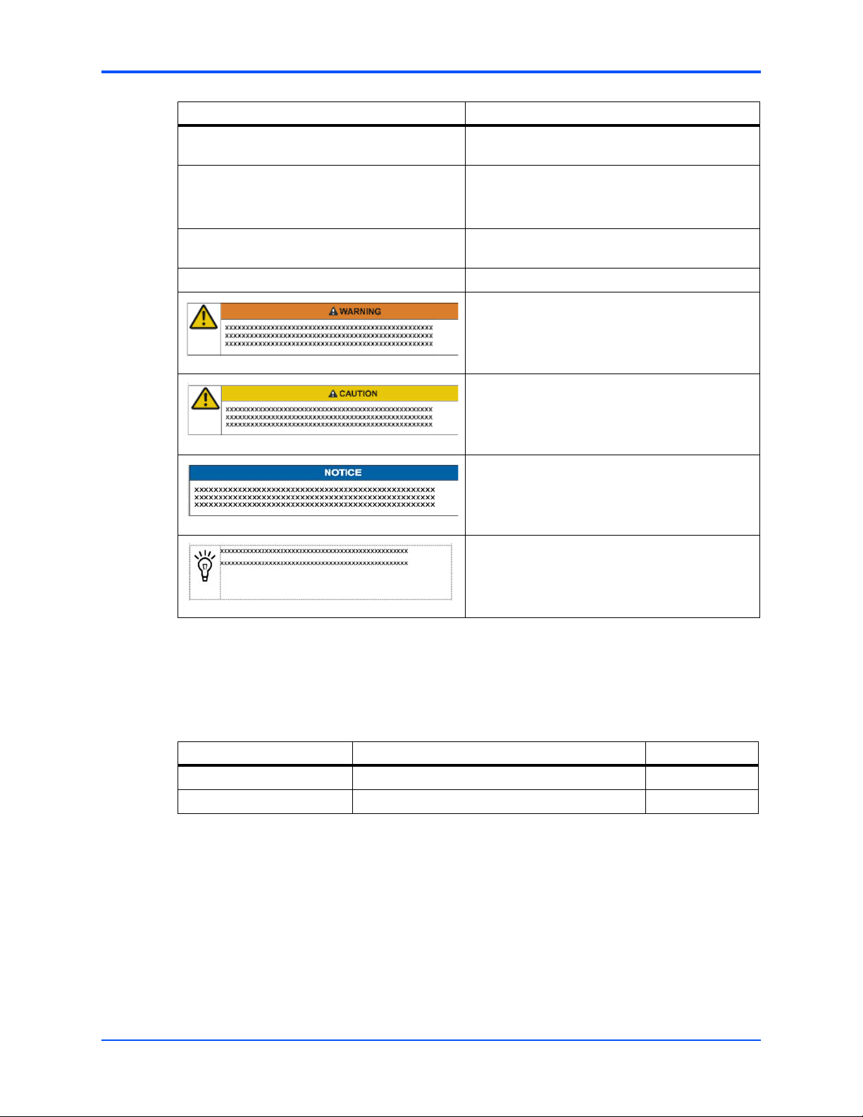
Indicates a hazardous situation which, if not
avoided, could result in death or serious injury
Indicates a hazardous situation which, if not
avoided, may result in minor or moderate injury
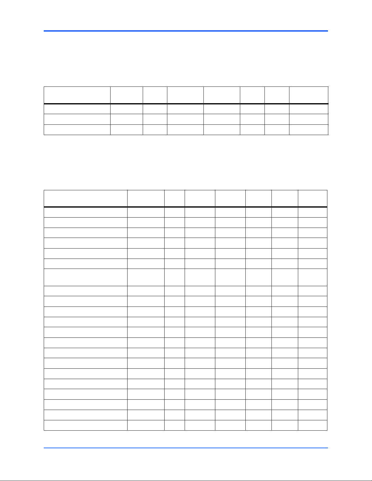
Summary of Changes
The next table provides information on the changes since the first release of this manual. This
edition supersedes all other releases.
Date Description of Change Replaces
April 2008 Updated to Emerson style. 6806800B66B
April 2007 Shm Fault Event OEM Sensor added. 6806800B66A
Indicates a property damage message
No danger encountered. Pay attention to important
information
AXP1406/AXP1600 Subsystem IPMI Programmer’s Reference (6806800B66C)
13
Page 14

About this Manual
Comments and Suggestions
We welcome and appreciate your comments on our documentation. We want to know what you
think about our manuals and how we can make them better.
Mail comments to us by filling out the following online form:
http://www.emersonnetworkpowerembeddedcomputing.com/ > Contact Us > Online Form
In “Area of Interest” select “Technical Documentation”. Be sure to include the title, part number,
and revision of the manual and tell us how you used it.
14
AXP1406/AXP1600 Subsystem IPMI Programmer’s Reference (6806800B66C)
Page 15

Supported IPMI Commands
1.1 Introduction
This chapter describes the different commands supported by the Centellis 3000 series
platforms. Command categories are as follows:
z Standard IPMI Commands
z PICMG 3.0 Commands
z Emerson and Pigeon Point OEM Commands
1.2 Standard IPMI Commands
1
The IPMC is fully compliant to the Intelligent Platform Management Interface v.1.5. This section
provides information on which IPMI commands are supported. Table entries marked with an “x”
indicate which FRU or ATCA blade supports a listed command.
1.2.1 Global IPMI Commands
The IPMC supports the following global IPMI commands.
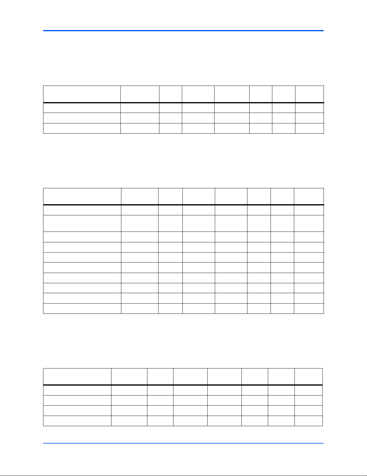
Table 1-1 Supported Global IPMI Commands
Active
NetFn Rq/Rs Command CMD
Get Device ID 0x06/0x07 0x01 X X X X X
Cold Reset 0x06/0x07 0x02 X X X X
Warm Reset 0x06/0x07 0x03 X X X
Get Self Test Result 0x06/0x07 0x04 X X X X X
Set ACPI Power State 0x06/0x07 0x06 X X *
Get ACPI Power State 0x06/0x07 0x07 X X *
Get Device GUID 0x06/0x07 0x08 X X X X X
ShelfMgr
Physical
ShelfMgr PEMs FTMs
ATCA
Blades
AXP1406/AXP1600 Subsystem IPMI Programmer’s Reference (6806800B66C)
15
Page 16
Supported IPMI Commands BMC WatchDog Timer Commands
1.2.2 BMC WatchDog Timer Commands
The IPMC supports the following BMC WatchDog Timer commands.
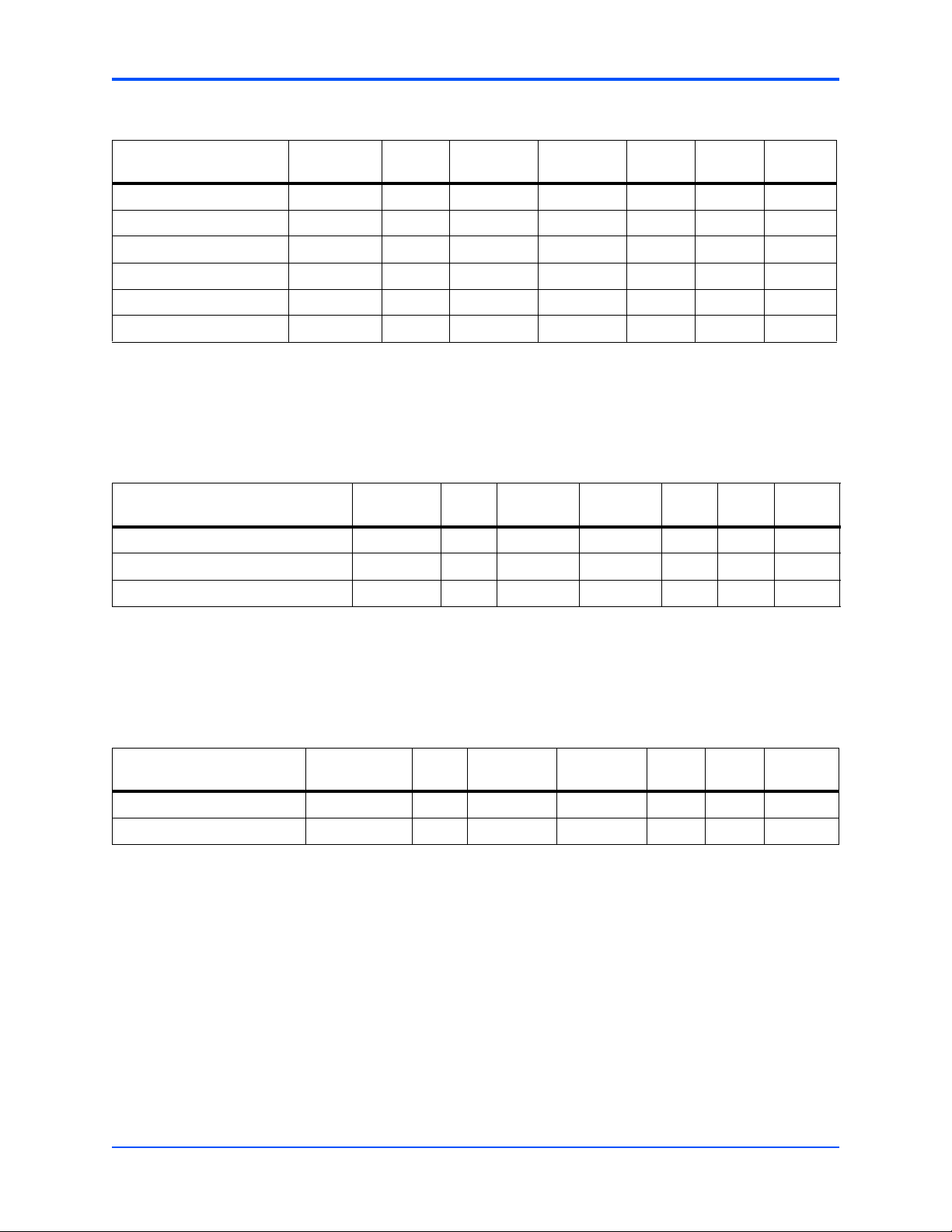
Table 1-2 Supported BMC WatchDog Timer Commands
NetFn
Command
Reset Watchdog Timer 0x06/0x07 0x22 X X X
Set Watchdog Timer 0x06/0x07 0x24 X X X
Get Watchdog Timer 0x06/0x07 0x25 X X X
R1/Rs CMD
Active
ShelfMgr
Physical
ShelfMgr PEMs FTMs
ATCA
Blades
1.2.3 BMC Device and Messaging Commands
The IPMC supports the following BMC device and messaging commands.
Table 1-3 Supported BMC Device and Messaging Commands
NetFn
Command
Set BMC Global Enables 0x06/0x07 0x2E X X X X X
Get BMC Global Enables 0x06/0x07 0x2F X X X X X
Clear Message Flags 0x06/0x07 0x30 X X X X X
Get Message Flags 0x06/0x07 0x31 X X X X X
Send Message 0x06/0x07 0x34 X X X X X
Get System GUID 0x06/0x07 0x37 X X X X X
Rq/Rs CMD
Active
ShelfMgr
Physical
ShelfMgr PEMs FTMs
ATCA
Blades
Get Channel Authentication
Capabilities
Get Session Challenge 0x06/0x07 0x39 X X X X X
Activate Session 0x06/0x07 0x3A X X X X X
Set Session Privilege Level 0x06/0x07 0x3B X X X X X
Close Session 0x06/0x07 0x3C X X X X X
Get Session Info 0x06/0x07 0x3D X X X X X
Get AuthCode 0x06/0x07 0x3F X X X X X
Set Channel Access 0x06/0x07 0x40 X X X X X
Get Channel Access 0x06/0x07 0x41 X X X X X
Get Channel Info Command 0x06/0x07 0x42 X X X X X
Set User Access Command 0x06/0x07 0x43 X X X X X
Get User Access Command 0x06/0x07 0x44 X X X X X
Set User Name 0x06/0x07 0x45 X X X X X
Get User Name Command 0x06/0x07 0x46 X X X X X
Set User Password Command 0x06/0x07 0x47 X X X X X
0x06/0x07 0x38 X X X X X
16
AXP1406/AXP1600 Subsystem IPMI Programmer’s Reference (6806800B66C)
Page 17
Chassis Device Commands Supported IPMI Commands
1.2.4 Chassis Device Commands
The IPMC supports the following chassis device commands.
Table 1-4 Supported Chassis Device Commands
NetFn
Command
Get Chassis Capabilities 0x00/0x01 0x00 X X
Get Chassis Status 0x00/0x01 0x01 X X
Chassis Control 0x00/0x01 0x02 X X
Set Chassis Capabilities 0x00/0x01 0x05 X X
Set System Boot Options* 0x00/0x01 0x08 X
Get System Boot Options* 0x00/0x01 0x09 X
*The data portion of these commands are blade-specific. Refer to the respective blade specification.
Rq/Rs CMD
Active
ShelfMgr
Physical
ShelfMgr PEMs FTMs
1.2.5 Event Commands
The IPMC supports the following event commands.
Table 1-5 Supported Event Commands
Active
Command NetFn Rq/Rs CMD
Set Event Receiver 0x04/0x05 0x00 X X X X X
Get Event Receiver 0x04/0x05 0x01 X X X X X
ShelfMgr
Physical
ShelfMgr PEMs FTMs
ATCA
Blades
ATCA
Blades
Platform Event (a.k.a. “Event
Message”)
*ATCA-F101 supports this command.
0x04/0x05 0x02 X X *
1.2.6 PEF and Alerting Commands
The IPMC supports the following PEF and alerting commands.
Table 1-6 Supported PEF and Alerting Commands
NetFn
Command
Get PEF Capabilities 0x04/0x05 0x10 X X
Arm PEF Postpone Timer 0x04/0x05 0x11 X X
Set PEF Configuration Parameters 0x04/0x05 0x12 X X
Get PEF Configuration Parameters 0x04/0x05 0x13 X X
Rq/Rs CMD
Active
ShelfMgr
Physical
ShelfMgr PEMs FTMs
ATCA
Blades
AXP1406/AXP1600 Subsystem IPMI Programmer’s Reference (6806800B66C)
17
Page 18
Supported IPMI Commands Sensor Device Commands
Table 1-6 Supported PEF and Alerting Commands (continued)
NetFn
Command
Set Last Processed Event ID 0x04/0x05 0x14 X X
Get Last Processed Event ID 0x04/0x05 0x15 X X
Alert Immediate 0x04/0x05 0x16 X X
PET Acknowledge 0x04/0x05 0x17 X X
Rq/Rs CMD
Active
ShelfMgr
Physical
ShelfMgr PEMs FTMs
1.2.7 Sensor Device Commands
The IPMC supports the following sensor device commands.
Table 1-7 Supported Sensor Device Commands
NetFn
Command
Get Device SDR Info 0x04/0x05 0x20 X X X X X
Get Device SDR 0x04/0x05 0x21 X X X X X
Reserve Device SDR Repository 0x04/0x05 0x22 X X X X X
Get Sensor Reading Factors 0x04/0x05 0x23 X X X X X
Set Sensor Hysteresis 0x04/0x05 0x24 X X X X X
Get Sensor Hysteresis 0x04/0x05 0x25 X X X X X
Rq/Rs CMD
Active
ShelfMgr
Physical
ShelfMgr PEMs FTMs
ATCA
Blades
ATCA
Blades
Set Sensor Threshold 0x04/0x05 0x26 X X X X X
Get Sensor Threshold 0x04/0x05 0x27 X X X X X
Set Sensor Event Enable 0x04/0x05 0x28 X X X X X
Get Sensor Event Enable 0x04/0x05 0x29 X X X X X
Re-arm Sensor Events 0x04/0x05 0x2a X X *
Get Sensor Event Status 0x04/0x05 0x2b X X X X X
Get Sensor Reading 0x04/0x05 0x2d X X X X X
Set Sensor Type 0x04/0x05 0x2e X X *
Get Sensor Type 0x04/0x05 0x2f X X X X X
*ATCA-F101 Supports this command.
18
AXP1406/AXP1600 Subsystem IPMI Programmer’s Reference (6806800B66C)
Page 19
FRU Device Commands Supported IPMI Commands
1.2.8 FRU Device Commands
The IPMC supports the following FRU device commands.
Table 1-8 Supported FRU Commands
Active
Command NetFn Rq/Rs CMD
Get FRU Inventory Area Info 0x0A/0x0B 0x10 X X X X X
Read FRU Data 0x0A/0x0B 0x11 X X X X X
Write FRU Data 0x0A/0x0B 0x12 X X X X X
ShelfMgr
Physical
ShelfMgr PEMs FTMs
1.2.9 SDR Device Commands
The IPMC supports the following SDR device commands.
Table 1-9 Supported SDR Device Commands
NetFn
Command
Get SDR Repository Info 0x0A/0x0B 0x20 X
Get SDR Repository
Allocation Info
Reserve SDR Repository 0x0A/0x0B 0x22 X
Get SDR 0x0A/0x0B 0x23 X
Add SDR 0x0A/0x0B 0x24 X
Rq/Rs CMD
0x0A/0x0B 0x21
Active
ShelfMgr
Physical
ShelfMgr PEMs FTMs
ATCA
Blades
ATCA
Blades
Partial Add SDR 0x0A/0x0B 0x25 X
Delete SDR 0x0A/0x0B 0x26 X
Clear SDR Repository 0x0A/0x0B 0x27 X
Get SDR Repository Time 0x0A/0x0B 0x28 X
Set SDR Repository Time 0x0A/0x0B 0x29 X
1.2.10 SEL Device Commands
The IPMC supports the following SEL device commands.
Table 1-10 Supported SEL Commands
NetFn
Command
Get SEL Info 0x0A/0x0B 0x40 X
Get SEL Allocation Info 0x0A/0x0B 0x41 X
Reserve SEL 0x0A/0x0B 0x42 X
Get SEL Entry 0x0A/0x0B 0x43 X X
Rq/Rs CMD
Active
ShelfMgr
Physical
ShelfMgr PEMs FTMs
ATCA
Blades
AXP1406/AXP1600 Subsystem IPMI Programmer’s Reference (6806800B66C)
19
Page 20
Supported IPMI Commands LAN Device Commands
Table 1-10 Supported SEL Commands (continued)
NetFn
Command
Add SEL Entry 0x0A/0x0B 0x44 X X
Partial Add SEL Entry 0x0A/0x0B 0x45 X X
Delete SEL Entry 0x0A/0x0B 0x46 X X
Clear SEL 0x0A/0x0B 0x47 X X
Get SEL Time 0x0A/0x0B 0x48 X
Set SEL Time 0x0A/0x0B 0x49 X X
Rq/Rs CMD
Active
ShelfMgr
1.2.11 LAN Device Commands
The IPMC supports the following LAN device commands.
Table 1-11 Supported LAN Device Commands
NetFn
Command
Set LAN Configuration Parameters 0x0C/0x0D 0x01 X
Get LAN Configuration Parameters 0x0C/0x0D 0x02 X
Suspend BMC ARPs 0x0C/0x0D 0x03 X
Rq/Rs CMD
Active
ShelfMgr
Physical
ShelfMgr PEMs FTMs
Physical
ShelfMgr PEMs FTMs
ATCA
Blades
ATCA
Blades
1.2.12 Serial/Modem Device Commands
The IPMC supports the following serial/modem device commands.
Table 1-12 Supported Serial/Modem Device Commands
Active
Command NetFn Rq/Rs CMD
Set User Callback Options 0x0C/0x0D 0x1A X
Get User Callback Options 0x0C/0x0D 0x1B X
ShelfMgr
Physical
ShelfMgr PEMs FTMs
ATCA
Blades
20
AXP1406/AXP1600 Subsystem IPMI Programmer’s Reference (6806800B66C)
Page 21

PICMG 3.0 Commands Supported IPMI Commands
1.3 PICMG 3.0 Commands
The Emerson IPMC is a fully compliant AdvancedTCA Intelligent Platform Management
Controller. For example, it supports all required and mandatory AdvancedTCA commands as
defined in the PICMG 3.0 specification.
Table 1-13 Supported PICMG 3.0 Commands
Active
Command NetFn Rq/Rs CMD
Get PICMG Properties 0x2C/0x2D 0x00 X X X X X
Get Address Info 0x2C/0x2D 0x01 X X X X X
Get Shelf Address Info 0x2C/0x2D 0x02 X X
Set Shelf Address Info 0x2C/0x2D 0x03 X X
FRU Control 0x2C/0x2D 0x04 X X X X X
Get FRU LED Properties 0x2C/0x2D 0x05 X X X
Get LED Color Capabilities 0x2C/0x2D 0x06 X X X
Set FRU LED State 0x2C/0x2D 0x07 X X X
Get FRU LED State 0x2C/0x2D 0x08 X X X
Set IPMB State 0x2C/0x2D 0x09 X X X X X
Set FRU Activation Policy 0x2C/0x2D 0x0A X X X X X
Get FRU Activation Policy 0x2C/0x2D 0x0B X X X X X
Set FRU Activation 0x2C/0x2D 0x0C X X X X X
Get Device Locator Record ID0x2C/0x2D 0x0D X X X X X
Set Port State 0x2C/0x2D 0x0E X X X
Get Port State 0x2C/0x2D 0x0F X X X
Compute Power Properties 0x2C/0x2D 0x10 X X X X X
ShelfMgr
Physical
ShelfMgr PEMs FTMs
ATCA
Blades
Set Power Level 0x2C/0x2D 0x11 X X X X X
Get Power Level 0x2C/0x2D 0x12 X X X X X
Renegotiate Power 0x2C/0x2D 0x13 X
Get Fan Speed Properties 0x2C/0x2D 0x14 X
Set Fan Level 0x2C/0x2D 0x15 X
Get Fan Level 0x2C/0x2D 0x16 X
Bused Resource 0x2C/0x2D 0x17 X X
Get IPMB Link Info 0x2C/0x2D 0x18 X X
AXP1406/AXP1600 Subsystem IPMI Programmer’s Reference (6806800B66C)
21
Page 22
Supported IPMI Commands Emerson and Pigeon Point OEM Commands
1.4 Emerson and Pigeon Point OEM Commands
These commands can only be sent to the Emerson AXP1406 and AXP1600 Shelf Managers,
sending these commands to other shelf managers or IPMCs will result in error responses or
undefined behavior.
The SAM supports these OEM IPMI commands that are not defined in the IPMI 1.5 or PICMG
3.0 specifications.
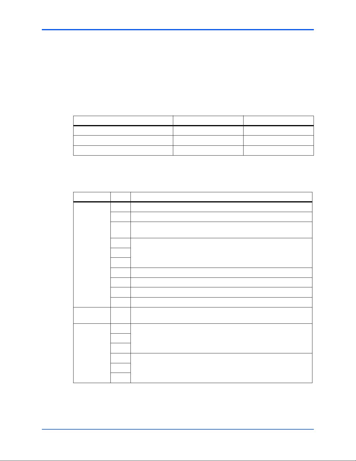
Table 1-14 OEM Command Summary
IPMI NetFn (Request/Response) Emerson OEM Command IPMI Cmd
Get Shelf Configuration Record 0x2E / 0x2F 0x01
Shelf Manager Switchover 0x2E / 0x2F 0x02
Set FRU Extracted 0x2E / 0x2F 0x03
This command gets the shelf configuration for the AXP1600.
Table 1-15 Get Shelf Configuration Record (Cmd = 0x01)
Byte Data field
Request data 1 Pigeon Point Systems IANA Enterprise number, LSB first
2 0x0A
3 0x40
0x00
4 IANA enterprise number for the desired record, LSB first
5
6
7 Record Type
8 Record Number
9 Offset within record
10 Count of bytes to retrieve
Response
data
1 Completion Code
2 Pigeon Point Systems IANA Enterprise number, LSB first
3
4
5 Requested bytes from the specified Shelf FRU record
…
0x0A
0x40
22
n
AXP1406/AXP1600 Subsystem IPMI Programmer’s Reference (6806800B66C)
Page 23
Emerson and Pigeon Point OEM Commands Supported IPMI Commands
This command requests a SAM switchover.
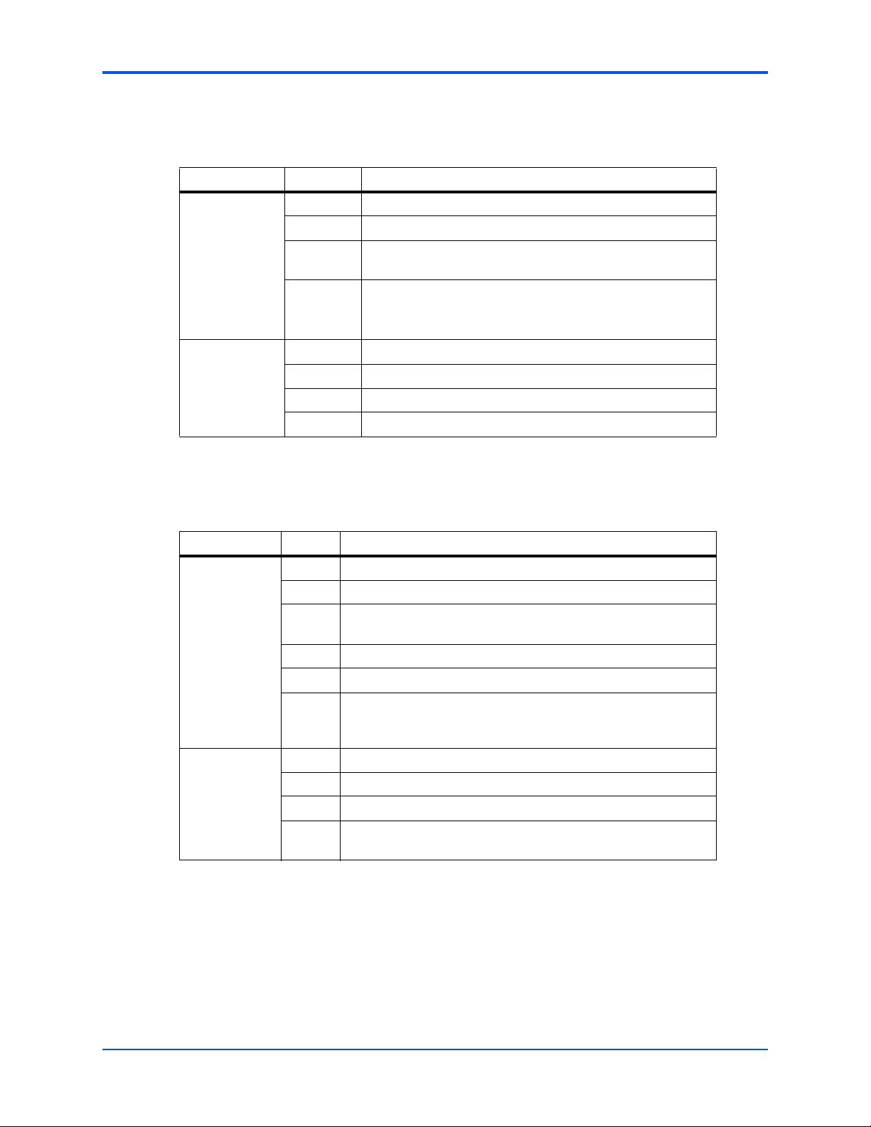
Table 1-16 Shelf Manager Switchover (Cmd = 0x02)
Byte Data field
Request data 1 Pigeon Point Systems IANA Enterprise number, LSB first
2 0x0A
3 0x40
0x00
4 Flags
0x00 Switchover, but do not reboot the active Shelf Manager
0x01 Switchover, and reboot the active Shelf Manager
Response data 1 Completion Code
2 0x0A
3 0x40
4 0x00
This command instructs the SAM to transition a FRU to the M0 (not installed) state.
Table 1-17 Set FRU Extracted (Cmd = 0x03)
Byte Data field
Request data 1 Pigeon Point Systems IANA Enterprise number, LSB first
2 0x0A
3 0x40
0x00
4 IPMB address
5FRU Id
6 Force option
0x00 Only extract specified FRU if it is in M7 state
0x01 Extract the specified FRU regardless of its current state
Response data 1 Completion Code
2 Pigeon Point Systems IANA Enterprise number, LSB first
3 0x0A
4 0x40
0x00
AXP1406/AXP1600 Subsystem IPMI Programmer’s Reference (6806800B66C)
23
Page 24

Supported IPMI Commands Emerson and Pigeon Point OEM Commands
24
AXP1406/AXP1600 Subsystem IPMI Programmer’s Reference (6806800B66C)
Page 25
FRU Information and Sensor Data Records
2.1 Introduction
This chapter introduces FRU information, e-keying, sensor overviews, and power configuration
data for each subcomponent of the AXP1406 and AXP1600 shelf. Information in this chapter
also includes:
z Total Power Consumption
z SAM1000 Physical Shelf Manager
z SAM1000 Active (Virtual) Shelf Manager
z Power Entry Module Sensor Data Records
Subcomponents include the Power Entry Modules (PEMs), upper and lower Fan Tray Modules
(FTMs), and the SAM1000 Shelf Management Alarm Module (SAMs), both physical and active.
All fan tray sensors are exposed by the Active SAM.
2
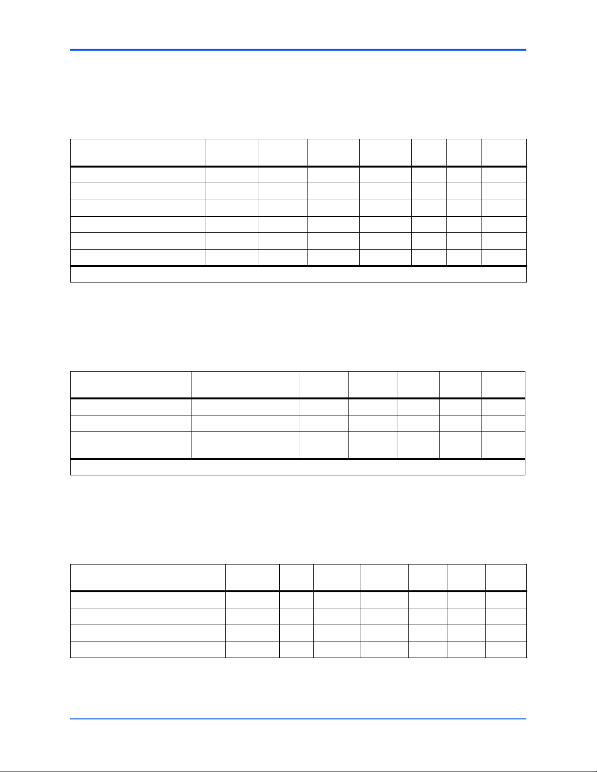
2.2 Total Power Consumption
The following table shows the total power requirements for the shelf. Power consumption
breakdown is shown in the next table.
Table 2-1 Total Power Consumption for AXP 1406 and AXP1600 Shelves
Amps per Fan Maximum Total Watts
AXP1406 Shelf
8 FTMs without AdvancedTCA Blades
AXP1600 Shelf
9 FTMs without AdvancedTCA Blades
Assumes the shelf is configured with 2 SAMs, 2 PEMs, and all FTMs running at full
speed.
AXP1406/AXP1600 Subsystem IPMI Programmer’s Reference (6806800B66C)
400 Watts
400 Watts
25
Page 26

FRU Information and Sensor Data Records SAM1000 Physical Shelf Manager
2.3 SAM1000 Physical Shelf Manager
This section describes in detail the physical SAM Shelf Manager, FRU data, power
configuration and sensors at IPMB addresses 0xFC and 0xFE. The information in this section
supports the SAM on both the AXP1406 and AXP1600 shelves. The AXP1600 FRU and sensor
data is highlighted and marked for ease of use.
2.3.1 SAM Physical FRU Information
The following tables provides the FRU information for the physical SAM on the AXP1406 and
AXP1600 shelves.
2.3.1.1 Physical Shelf Manager FRU Data, AXP1406
Common Header: Format Version = 1
Internal Use Area:
Version = 1
Board Info Area:
Version = 1
Language Code = 25
Mfg Date/Time = Mar 30 23:00:00 2005 (4862820 minutes since 1996)
Board Manufacturer = Pigeon Point Systems
Board Product Name = IPM Sentry ShMM-500
Board Serial Number = PPS0000000
Board Part Number = A
FRU Programmer File ID =
Product Info Area:
Version = 1
Language Code = 25
Manufacturer Name = Pigeon Point Systems
26
Product Name = IPM Sentry Shelf Manager
Product Part / Model# = 000000
Product Version = Rev 1.00
Product Serial Number = PPS0000000
Asset Tag =
AXP1406/AXP1600 Subsystem IPMI Programmer’s Reference (6806800B66C)
Page 27

SAM Physical FRU Information FRU Information and Sensor Data Records
FRU Programmer File ID =
Multi Record Area:
PICMG Board Point-to-Point Connectivity Record (ID=0x14)
Version = 0
2.3.1.2 Physical Shelf Manager FRU Data, AXP1600
Common Header: Version = 1
Language Code = 25
Mfg Date/Time = Jan 1 00:00:00 2006 (5260320 mi nutes since 1996)
Board Manufacturer = Pigeon Point Systems
Board Product Name = IPM Sentry ShMM-500
Board Serial Number = 08000000
Board Part Number = 01-W3911F11B
FRU Programmer File ID = SAM1000R.inf
Product Info Area:
Version = 1
Language Code = 25
Manufacturer Name = Motorola
Product Name = SAM1000
Product Part / Model# = 01-W2313F11A
Product Version = Rev 1.00
Product Serial Number = 12345678901
Asset Tag =
FRU Programmer File ID = SAM1000R.inf
Multi Record Area:
PICMG Board Point-to-Point Connectivity Record (ID=0x14)
Version = 0
AXP1406/AXP1600 Subsystem IPMI Programmer’s Reference (6806800B66C)
27
Page 28

FRU Information and Sensor Data Records E-Keying
2.3.2 E-Keying
The physical SAMs (IPMB 0xfc and 0xfe) each contain the following Point-to-Point
Connectivity Record:
PICMG Board Point-to-Point Connectivity Record (ID=0x14)
Version = 0
OEM GUID Count = 0
Link Descriptor:
Link Grouping ID = 0x00
Link Type = 0x01 PICMG®3.0 Base 10/100/1000 Base-T
Link Type Extension = 0x0 10/100/1000BASE-T Link (four-pair)
Link Designator = 0x101 Channel1/BaseInterface/Ports0
Link Descriptor:
Link Grouping ID = 0x00
Link Type = 0x01 PICMG®3.0 Base 10/100/1000 Base-T
Link Type Extension = 0x0 10/100/1000BASE-T Link (four-pair)
Link Designator = 0x102 Channel2/BaseInterface/Ports0
2.3.3 Power Configuration
The following table describes the power configuration for the Physical SAM.
Table 2-2 SAM Physical Power Configuration
Item Value Meaning
Dynamic power reconfiguration
support
Dynamic power configuration No Are the Power Draw levels fixed or these may vary if
Number of Power Draw Levels 1 The amount of possible power levels, normally 1
Early Power Draw Levels, Watt 20 Complete early power consumption including IPMC
Steady state Power Draw Levels,
Watt
No Possibility to change FRU power consumption without
switching it off, according to ATCA
additional components are hot inserted or onboard
components power consumption is changing
dynamically
20 Complete steady power consumption including IPMC
28
Transition from Early to Steady
levels, sec
AXP1406/AXP1600 Subsystem IPMI Programmer’s Reference (6806800B66C)
0 How long does board consumes early power. Early
power is normally bigger than steady
Page 29

Sensor Overview FRU Information and Sensor Data Records
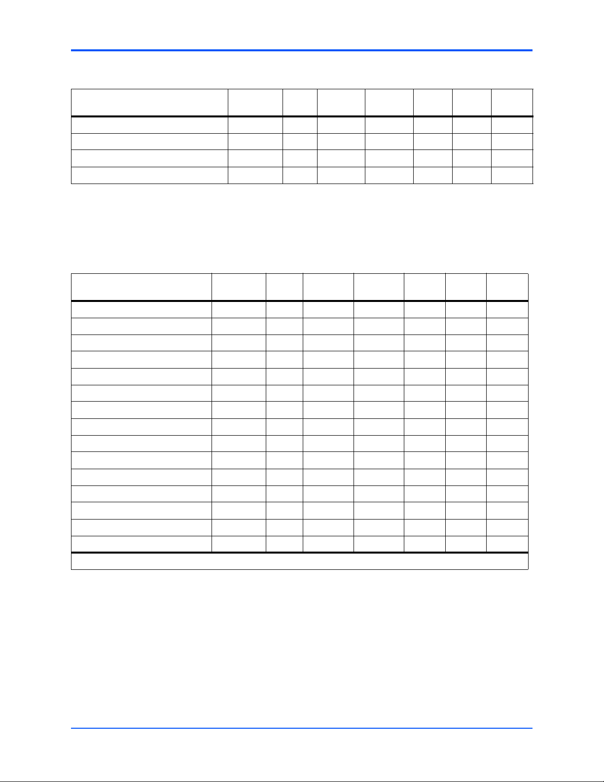
2.3.4 Sensor Overview
The following table lists all IPMI sensors available on the physical SAM at IPMB addresses
0xFC and 0xFE. The information in this section supports the SAM on both the AXP1406 and
AXP1600 shelves. The AXP1600 FRU and sensor data is highlighted and marked for ease of
use.
Table 2-3 Sensor Overview
Sensor
No. Sensor Name
0 FRU 0 HOT_SWAP Status State of FRU Discrete Always
1 IPMB LINK Status State of IPMB link Discrete Always
2 Vbat Voltage Analog Always
3 Vcc 3.3 V voltage Voltage Analog Always
4 +12 V voltage Voltage Analog Always
5 +1.8 V Voltage Analog Always
6 MAX6656 INT @1A Temperature Analog Always
7 MAX6656 EXT1 @1A Temperature Analog Always
8 MAX6656 EXT2 @1A Temperature Analog Always
9 PEM A Status PEM A Presence Discrete Always
10 PEM B Status PEM B Presence Discrete Always
11 NSC A
12 NSC B
13 AXP Backplane ID OEM Backplane Bus
14 12 V In B Valid Status Power Unit Discrete Always
15 12 V In A Valid Status Power Unit Discrete Always
1
1
Typ e of
Measurement
Status NSC Board
Status NSC Board
What does it
measure?
Presence
Presence
Ty pe
Sensor
Type Availability
Discrete Always
Discrete Always
Discrete Always
16 Fault Event OEM Shelf Manager
Rebooting Notifier
17 POST Results Status Management
Subsystem Health
18 Shelf FRU Info OEM Shelf Fru Info
Val idity
128 CPLD State OEM Master and
Backup Shelf
Manager State
1. These are additional sensors on the SAM1000 for the AXP1600.
AXP1406/AXP1600 Subsystem IPMI Programmer’s Reference (6806800B66C)
Discrete Always
Discrete Always
Discrete Always
Discrete Always
29
Page 30

FRU Information and Sensor Data Records SAM Physical Shelf Manager Analog Sensors
2.3.5 SAM Physical Shelf Manager Analog Sensors
The physical shelf managers at IPMB addresses 0xFC and 0xFE present the following analog
sensors:
z Voltage Sensors
z Temperature Sensors
The following tables describe the analog sensors available on the physical SAM. The
information in this section supports the SAM on both the AXP1406 and AXP1600 shelves. The
AXP1600 FRU and sensor data is highlighted and marked for ease of use.
2.3.5.1 Voltage Sensors
The following table describes the analog voltage sensors on the physical SAM.
Table 2-4 Sensor No. 2 Vbat
Feature Raw Value/Description Interpreted Value
Sensor Name Vbat
Device
Sensor Type 0x02 Voltage
Class 0x01 Threshold
Sensor Owner LUN 0x00
Entity ID 0xF0 PICMG Shelf Management
Controller
Entity Instance 0x60
Rearm mode Auto
Hysteresis support No
Threshold access support Readable/Settable
Event message control Entire Sensor only
Readable threshold mask,
Settable threshold mask (bytes
19, 20)
Reading Type Unsigned
Lower critical threshold 0x00 0 Volts
Upper critical threshold 0xFF 3.315 Volts
0x12, 0x12 Upper and Lower Critical
Thresholds are Readable and
Settable
30
AXP1406/AXP1600 Subsystem IPMI Programmer’s Reference (6806800B66C)
Page 31

SAM Physical Shelf Manager Analog Sensors FRU Information and Sensor Data Records
Table 2-5 Sensor No. 3 3.3 V Voltage
Feature Raw Value/Description Interpreted Value
Sensor Name Vcc 3.3 V voltage
Device
Sensor Type 0x02 Voltage
Class 0x01 Threshold
Sensor Owner LUN 0x00
Entity ID 0xF0 PICMG Shelf Management
Controller
Entity Instance 0x60
Rearm mode Auto
Hysteresis support No
Threshold access support Readable/Settable
Event message control Entire Sensor only
Readable threshold mask,
Settable threshold mask (bytes
19, 20)
Reading Type Unsigned
Lower critical threshold 0x73 3.0245 Volts
Upper critical threshold 0x88 3.5768 Volts
0x12, 0x12 Upper and Lower Critical
Thresholds are Readable and
Settable
Table 2-6 Sensor No. 4 +12 V Voltage
Feature Raw Value/Description Interpreted Value
Sensor Name +12 V voltage
Device
Sensor Type 0x02 Voltage
Class 0x01 Threshold
Sensor Owner LUN 0x00
Entity ID 0xF0 PICMG Shelf Management
Controller
Entity Instance 0x60
Rearm mode Auto
Hysteresis support No
Threshold access support Readable/Settable
Event message control Entire Sensor only
Readable threshold mask,
AXP1406/AXP1600 Subsystem IPMI Programmer’s Reference (6806800B66C)
31
Page 32

FRU Information and Sensor Data Records SAM Physical Shelf Manager Analog Sensors
Table 2-6 Sensor No. 4 +12 V Voltage (continued)
Feature Raw Value/Description Interpreted Value
Settable threshold mask (bytes
19, 20)
Reading Type Unsigned
Lower critical threshold 0x00 0 Volts
Upper critical threshold 0xFF 15.81 Volts
Table 2-7 Sensor No. 5 +1.8 V
Feature Raw Value/Description Interpreted Value
Sensor Name +1.8 V
Type of measurement Voltage
Device
Sensor Type 0x02 Voltage
Class 0x01 Threshold
0x12, 0x12 Upper and Lower Critical
Thresholds are Readable and
Settable
Sensor Owner LUN 0x00
Entity ID 0xF0 PICMG Shelf Management
Entity Instance 0x60
Rearm mode Auto
Hysteresis support No
Threshold access support Readable/Settable
Event message control Entire Sensor only
Readable threshold mask,
Settable threshold mask (bytes
19, 20)
Reading Type Unsigned
Upper critical threshold 0xFF 2.499 Volts
2.3.5.2 Temperature Sensors
The following tables describe the analog temperature sensors available on the physical SAM.
Table 2-8 Sensor No. 6 MAX6656 INT@1A
Controller
0x10, 0x10 Upper Critical Threshold is
Readable and Settable
32
Feature Raw Value/Description Interpreted Value
Sensor Name MAX6656 INT @1A
Device
Sensor Type 0x01 Temperature
Class 0x01 Threshold
AXP1406/AXP1600 Subsystem IPMI Programmer’s Reference (6806800B66C)
Page 33

SAM Physical Shelf Manager Analog Sensors FRU Information and Sensor Data Records
Table 2-8 Sensor No. 6 MAX6656 INT@1A (continued)
Feature Raw Value/Description Interpreted Value
Sensor Owner LUN 0x00
Entity ID 0xF0 PICMG Shelf Management
Controller
Entity Instance 0x60
Rearm mode Auto
Hysteresis support Readable and Settable
Threshold access support Readable/Settable
Event message control Entire Sensor only
Readable threshold mask,
Settable threshold mask (bytes
19, 20)
Reading Type 2's Complement
Upper Non-Critical, Critical and
Non-Recoverable threshold
0x38, 0x38 Upper Non-Critical, Critical and
Non-Recoverable Thresholds
are Readable and Settable
0x50, 0x5A, 0x64 (80, 90, 100) Centigrade
Table 2-9 Sensor No. 7 MAX6656 EXT1@1A
Feature Raw Value/Description Interpreted Value
Sensor Name MAX6656 EXT1 @1A
Device
Sensor Type 0x01 Temperature
Class 0x01 Threshold
Sensor Owner LUN 0x00
Entity ID 0xF0 PICMG Shelf Management
Controller
Entity Instance 0x60
Rearm mode Auto
Hysteresis support Readable and Settable
Threshold access support Readable/Settable
Event message control Entire Sensor only
Readable threshold mask,
Settable threshold mask (bytes
19, 20)
Reading Type 2's Complement
Upper Non-Critical, Critical and
Non-Recoverable threshold
AXP1406/AXP1600 Subsystem IPMI Programmer’s Reference (6806800B66C)
0x38, 0x38 Upper Non-Critical, Critical and
0x50, 0x5A, 0x64 (80, 90, 100) Centigrade
Non-Recoverable Thresholds
are Readable and Settable
33
Page 34

FRU Information and Sensor Data Records SAM Module Discrete Sensors
Table 2-10 Sensor No. 8 MAX6656 EXT2@1A
Feature Raw Value/Description Interpreted Value
Sensor Name MAX6656 EXT2 @1A
Device
Sensor Type 0x01 Temperature
Class 0x01 Threshold
Sensor Owner LUN 0x00
Entity ID 0xF0 PICMG Shelf Management
Controller
Entity Instance 0x60
Rearm mode Auto
Hysteresis support Readable and Settable
Threshold access support Readable/Settable
Event message control Entire Sensor only
Readable threshold mask,
Settable threshold mask (bytes
19, 20)
Reading Type 2's Complement
Upper Non-Critical, Critical and
Non-Recoverable threshold
0x38, 0x38 Upper Non-Critical, Critical and
0x50, 0x5A, 0x64 (80, 90, 100) Centigrade
2.3.6 SAM Module Discrete Sensors
The physical shelf managers at IPMB addresses 0xFC and 0xFE present the following discrete
sensors:
z Hot Swap Sensor
z IPMB Link Sensor
z PEM A Sensor
z PEM B Sensor
z AXP Backplane ID Sensor
z +12 V B Valid Sensor
z +12 V A Valid Sensor
Non-Recoverable Thresholds
are Readable and Settable
34
z Fault Event Sensor
z POST Results Sensor
z Shelf FRU Info Sensor
z CPLD State Sensor
AXP1406/AXP1600 Subsystem IPMI Programmer’s Reference (6806800B66C)
Page 35

SAM Module Discrete Sensors FRU Information and Sensor Data Records
2.3.6.1 Hot Swap Sensor
The following table describes the discrete hot swap sensor available on the physical SAM.
Table 2-11 Sensor No. 0 FRU 0 HOT_SWAP
Feature Raw Value/Description Interpreted Value
Sensor Name FRU 0 HOT_SWAP
Type of Measurement Hot Swap State
Class Discrete
Event/Reading Type 0x6F Sensor-specific
Sensor Type 0xF0 Hot Swap
Sensor Owner LUN 0x00
Entity ID 0xF0 PICMG Shelf Management
Controller
Entity Instance 0x60
Rearm mode Auto
Event message control Entire Sensor only
Assertion Event Mask (bytes 15,
16)
Deassertion Event Mask (bytes
17,18)
Discrete Reading Mask (bytes
19, 20)
Reading Definition According to PICMG 3.0
2.3.6.2 IPMB Link Sensor
The following table describes the discrete IPMB link sensor available on the physical SAM.
Table 2-12 Sensor No. 1 IPMB Link
Feature Raw Value/Description Interpreted Value
Sensor Name IPMB LINK
Type of Measurement IPMB Link State
Class Discrete
Event/Reading Type 0x6F Sensor-specific
Sensor Type 0xF1 IPMB Link
0xFF, 0x00
0x00, 0x00
0xFF, 0x00 Supports 8 Successive States
Sensor Owner LUN 0x00
Entity ID 0xF0 PICMG Shelf Management
Entity Instance 0x60
Rearm mode Auto
AXP1406/AXP1600 Subsystem IPMI Programmer’s Reference (6806800B66C)
Controller
35
Page 36

FRU Information and Sensor Data Records SAM Module Discrete Sensors
Table 2-12 Sensor No. 1 IPMB Link (continued)
Feature Raw Value/Description Interpreted Value
Event message control Entire Sensor only
Assertion Event Mask (bytes
15,16)
Deassertion Event Mask (bytes
17,18)
Discrete Reading Mask (bytes
19, 20)
Reading Definition According to PICMG 3.0
2.3.6.3 PEM A Sensor
The following table describes the discrete PEM A sensor available on the physical SAM.
Table 2-13 Sensor No. 9 PEM A
Feature Raw Value/Description Interpreted Value
Sensor Name PEM A
Type of Measurement Presence
Class Discrete
Event/Reading Type 0x6F Sensor-specific
Sensor Type 0x25 Entity Presence
Sensor Owner LUN 0x00
0x0F, 0x00
0x00, 0x00
0x0F, 0x00 Supports 4 Successive States
Entity ID 0x0A Power Supply
Entity Instance 0x00
Rearm mode Auto
Event message control Entire Sensor only
Assertion Event Mask (bytes
15,16)
Deassertion Event Mask (bytes
17,18)
Discrete Reading Mask (bytes
19, 20)
Reading Definition According to IPMI 1.5
0x03, 0x00
0x00, 0x00
0x03, 0x00 Supports 2 Successive States
36
AXP1406/AXP1600 Subsystem IPMI Programmer’s Reference (6806800B66C)
Page 37

SAM Module Discrete Sensors FRU Information and Sensor Data Records
2.3.6.4 PEM B Sensor
The following table describes the discrete PEM B sensor available on the physical SAM.
Table 2-14 Sensor No. 10 PEM B
Feature Raw Value/Description Interpreted Value
Sensor Name PEM B
Type of Measurement Presence
Class Discrete
Event/Reading Type 0x6F Sensor-specific
Sensor Type 0x25 Entity Presence
Sensor Owner LUN 0x00
Entity ID 0x0A Power Supply
Entity Instance 0x01
Rearm mode Auto
Event message control Entire Sensor only
Assertion Event Mask (bytes
15,16)
Deassertion Event Mask (bytes
17,18)
Discrete Reading Mask (bytes
19, 20)
Reading Definition According to IPMI 1.5
0x03, 0x00
0x00, 0x00
0x03, 0x00 Supports 2 Successive States
Two additional NSC Presence sensor support the SAM used in the AXP1600 shelf.
Table 2-15 Sensor No. 11 NSC A (AXP1600 Only)
Feature Raw Value/Description Interpreted Value
Sensor Name NSC A
Type of Measurement Presence
Class Discrete
Event/Reading Type 0x6F Sensor-specific
Sensor Type 0x25 Entity Presence
Sensor Owner LUN 0x00
Entity ID 0x0B (add-in card) Power Supply
AXP1406/AXP1600 Subsystem IPMI Programmer’s Reference (6806800B66C)
37
Page 38

FRU Information and Sensor Data Records SAM Module Discrete Sensors
Table 2-15 Sensor No. 11 NSC A (AXP1600 Only) (continued)
Feature Raw Value/Description Interpreted Value
Entity Instance 0x00
Rearm mode Auto
Event message control Entire Sensor only
Assertion Event Mask (bytes
15,16)
Deassertion Event Mask (bytes
17,18)
Discrete Reading Mask (bytes
19, 20)
Reading Definition According to IPMI 1.5
0x03, 0x00
0x00, 0x00
0x03, 0x00 Supports 2 Successive States
Table 2-16 Sensor No. 12 NSC B (AXP1600 Only)
Feature Raw Value/Description Interpreted Value
Sensor Name NSC B
Type of Measurement Presence
Class Discrete
Event/Reading Type 0x6F Sensor-specific
Sensor Type 0x25 Entity Presence
Sensor Owner LUN 0x00
Entity ID 0x0B (add-in card Power Supply
Entity Instance 0x01
Rearm mode Auto
Event message control Entire Sensor only
38
Assertion Event Mask (bytes
15,16)
Deassertion Event Mask (bytes
17,18)
Discrete Reading Mask (bytes
19, 20)
Reading Definition According to IPMI 1.5
AXP1406/AXP1600 Subsystem IPMI Programmer’s Reference (6806800B66C)
0x03, 0x00
0x00, 0x00
0x03, 0x00 Supports 2 Successive States
Page 39

SAM Module Discrete Sensors FRU Information and Sensor Data Records
2.3.6.5 AXP Backplane ID Sensor
The following table describes the discrete AXP backplane ID sensor available on the physical
SAM. For more detail on this sensor, refer to AXP Backplane ID (Emerson OEM) on page 138.
Table 2-17 Sensor No. 13 AXP Backplane ID
Feature Raw Value/Description Interpreted Value
Sensor Name AXP Backplane ID
Type of Measurement Specifies Bus Type of the
Backplane
Class Discrete
Event/Reading Type 0x6F Sensor-specific
Sensor Type 0xDB OEM-reserved
Sensor Owner LUN 0x00
Entity ID 0xF0 PICMG Shelf Management
Controller
Entity Instance 0x60
Rearm mode Auto
Event message control Entire Sensor only
Assertion Event Mask (bytes
15,16)
Deassertion Event Mask (bytes
17,18)
Discrete Reading Mask (bytes
19, 20)
Reading Definition According to Motorola XXXX
2.3.6.6 +12 V B Valid Sensor
The following table describes the discrete +12 V B valid sensor available on the physical SAM.
Table 2-18 Sensor No. 14 12 V B Valid
Feature Raw Value/Description Interpreted Value
Sensor Name 12 V In B Valid
Type of Measurement State of Power Unit B
Class Discrete
Event/Reading Type 0x03 'digital' Discrete
0x01, 0x00
0x00, 0x00
0x01 0x00 Supports 1 Successive State
Sensor Type 0x09 Power Unit
Sensor Owner LUN 0x00
Entity ID 0xF0 PICMG Shelf Management
Entity Instance 0x60
AXP1406/AXP1600 Subsystem IPMI Programmer’s Reference (6806800B66C)
Controller
39
Page 40

FRU Information and Sensor Data Records SAM Module Discrete Sensors
Table 2-18 Sensor No. 14 12 V B Valid (continued)
Feature Raw Value/Description Interpreted Value
Rearm mode Auto
Event message control Entire Sensor only
Assertion Event Mask (bytes
15,16)
Deassertion Event Mask (bytes
17,18)
0x03, 0x00
0x00, 0x00
Discrete Reading Mask (bytes
19, 20)
Reading Definition According to IPMI 1.5
2.3.6.7 +12 V A Valid Sensor
The following table describes the discrete +12V A valid sensor available on the physical SAM.
Table 2-19 Sensor No. 15 12 V A Valid
Feature Raw Value/Description Interpreted Value
Sensor Name 12 V In A Valid
Type of Measurement State of Power Unit A
Class Discrete
Event/Reading Type 0x03 'digital' Discrete
Sensor Type 0x09 Power Unit
Sensor Owner LUN 0x00
Entity ID 0xF0 PICMG Shelf Management
Entity Instance 0x60
Rearm mode Auto
Event message control Entire Sensor only
0x03, 0x00 Supports 2 Successive States
Controller
40
Assertion Event Mask (bytes
15,16)
Deassertion Event Mask (bytes
17,18)
Discrete Reading Mask (bytes
19, 20)
Reading Definition According to IPMI 1.5
AXP1406/AXP1600 Subsystem IPMI Programmer’s Reference (6806800B66C)
0x03, 0x00
0x00, 0x00
0x03, 0x00 Supports 2 Successive States
Page 41

SAM Module Discrete Sensors FRU Information and Sensor Data Records
2.3.6.8 Fault Event Sensor
The following table describes the discrete fault event sensor available on the physical SAM.
Table 2-20 Sensor No. 16 Fault Event
Feature Raw Value/Description Interpreted Value
Sensor Name Fault Event
Type of Measurement Reports that the Shelf Manager
has Rebooted.
Class Discrete
Event/Reading Type 0x6F Sensor-specific
Sensor Type 0xDC OEM-reserved
Sensor Owner LUN 0x00
Entity ID 0xF0 PICMG Shelf Management
Controller
Entity Instance 0x60
Rearm mode Auto
Event message control Entire Sensor only
Assertion Event Mask (bytes
15,16)
Deassertion Event Mask (bytes
17,18)
Discrete Reading Mask (bytes
19, 20)
Reading Definition According to Motorola XXX
2.3.6.9 POST Results Sensor
The following table describes the discrete POST results sensor available on the physical SAM.
For more information on this sensor, refer to POST Results (Emerson OEM) on page 138.
Table 2-21 Sensor No. 17 POST Results
Feature Raw Value/Description Interpreted Value
Sensor Name POST Results
Type of Measurement POST Results
Class Discrete
Event/Reading Type 0x06 'digital' Discrete
Sensor Type 0x28 Management Subsystem Health
Sensor Owner LUN 0x00
Entity ID 0xF0 PICMG Shelf Management
Entity Instance 0x60
0x01, 0x00
0x00, 0x00
0x01, 0x00 Supports 1 State
Controller
AXP1406/AXP1600 Subsystem IPMI Programmer’s Reference (6806800B66C)
41
Page 42

FRU Information and Sensor Data Records SAM Module Discrete Sensors
Table 2-21 Sensor No. 17 POST Results (continued)
Feature Raw Value/Description Interpreted Value
Rearm mode Auto
Event message control Entire Sensor only
Assertion Event Mask (bytes
15,16)
Deassertion Event Mask (bytes
17,18)
0x02, 0x00
0x00, 0x00
Discrete Reading Mask (bytes
19, 20)
Reading Definition According to IPMI 1.5
2.3.6.10 Shelf FRU Info Sensor
The following table describes the discrete shelf FRU info sensor available on the physical SAM.
For more information on this sensor, refer to Shelf FRU Info (Emerson OEM) on page 139.
Table 2-22 Sensor No. 18 Shelf FRU Info
Feature Raw Value/Description Interpreted Value
Sensor Name Shelf FRU Info
Type of Measurement Basic validation of the Shelf
Class Discrete
Event/Reading Type 0x09 'digital' Discrete
Sensor Type 0xDD OEM-reserved
Sensor Owner LUN 0x00
Entity ID 0xF0 PICMG Shelf Management
0x03, 0x00 Supports 2 Successive States
FRU Info
Controller
42
Entity Instance 0x60
Rearm mode Auto
Event message control Entire Sensor only
Assertion Event Mask (bytes
15,16)
Deassertion Event Mask(bytes
17,18)
Discrete Reading Mask (bytes
19, 20)
Reading Definition According to Motorola XXX
AXP1406/AXP1600 Subsystem IPMI Programmer’s Reference (6806800B66C)
0x03, 0x00
0x00, 0x00
0x03, 0x00 Supports 2 Successive States
Page 43

SAM1000 Active (Virtual) Shelf Manager FRU Information and Sensor Data Records
2.3.6.11 CPLD State Sensor
The following table describes the discrete CPLD state sensor available on the physical SAM.
Table 2-23 Sensor No. 128 CPLD State
Feature Raw Value/Description Interpreted Value
Sensor Name CPLD State
Type of Measurement States of the Master and Backup
Shelf Managers
Class Discrete
Event/Reading Type 0x6F Sensor-specific
Sensor Type 0xDE OEM-reserved
Sensor Owner LUN 0x00
Entity ID 0xF0 PICMG Shelf Management
Controller
Entity Instance 0x60
Rearm mode Auto
Event message control Entire Sensor only
Assertion Event Mask (bytes
15,16)
Deassertion Event Mask (bytes
17,18)
Discrete Reading Mask (bytes
19, 20)
Reading Definition According to Motorola XXX
0xF7, 0x07
0x00, 0x00
0xF7, 0x07 Supports 10 States
2.4 SAM1000 Active (Virtual) Shelf Manager
This section describes in detail all available IPMI sensors of the Active SAM1000 at IPMB
address 0x20. The information in this section supports the SAM on both the AXP1406 and
AXP1600 shelves. The AXP1600 FRU and sensor data is highlighted and/or marked for ease
of use.
2.4.1 FRU Information
FRU 0 of address 0x20 corresponds to the main FRU information of the respective Physical
SAM that is running as the Active SAM; it could be either FRU 0 of IPMB address 0xFC or FRU
0 of IPMB address 0xFE.
Active Shelf Manager FRU Data, AXP1406
There are an additional eight managed FRUs (FRUs 1 to 8) that correspond to each of the eight
fan trays that cool the chassis. The Active SAM FRU information is addressed as FRU 254
which is cached information from data stored as a FRU 1 in each of the PEMs (IPMB addresses
0x66 and 0x68).
AXP1406/AXP1600 Subsystem IPMI Programmer’s Reference (6806800B66C)
43
Page 44

FRU Information and Sensor Data Records FRU Information
Active Shelf Manager FRU Data, AXP1600
There are an additional nine managed FRUs (FRUs 1 to 9) that correspond to each of the nine
fan trays that cool the chassis. The Active SAM FRU information is addressed as FRU 254
which is cached information from data stored as a FRU 1 in each of the PEMs (IPMB addresses
0x66 and 0x68).
The following tables show an example of the output obtained when retrieving FRU information
using the CLIA tool of the Active SAM.
2.4.1.1 Active Shelf Manager FRU Data, AXP1406
# clia fruinfo 20 254
Pigeon Point Shelf Manager Command Line Interpreter
66: FRU # 1, FRU Info
Common Header: Format Version = 1
Chassis Info Area:
Version = 1
Chassis Type = (2)
Chassis Part Number = CHS1406
Chassis Serial Number = 0000001
Board Info Area:
Version = 1
Language Code = 25
Mfg Date/Time = Mar 29 00:00:00 2006 (5385600 minutes since 1996)
Board Manufacturer = Motorola
Board Product Name = CHS1406
Board Serial Number = 0000001
Board Part Number = CHS1406
44
FRU Programmer File ID = CHS1406.inf
Product Info Area:
Version = 1
AXP1406/AXP1600 Subsystem IPMI Programmer’s Reference (6806800B66C)
Page 45

FRU Information FRU Information and Sensor Data Records
Language Code = 25
Manufacturer Name = Motorola
Product Name = CHS1406
Product Part / Model# = CHS1406
Product Version = Rev. 1
Product Serial Number = 0000001
Asset Tag =
FRU Programmer File ID = CHS1406.inf
Multi Record Area:
PICMG Shelf Manager IP Connection Record (ID=0x13)
Version = 1
Record Type = Management Access Record
Version = 2
Sub-Record Type: Component Name (0x05)
PICMG Address Table Record (ID=0x10)
Version = 0
PICMG Backplane Point-to-Point Connectivity Record (ID=0x04)
Version = 0
PICMG Backplane Point-to-Point Connectivity Record (ID=0x04)
Version = 0
PICMG Shelf Power Distribution Record (ID=0x11)
Version = 0
PICMG Radial IPMB-0 Link Mapping Record (ID=0x15)
Version = 0
AXP1406/AXP1600 Subsystem IPMI Programmer’s Reference (6806800B66C)
45
Page 46

FRU Information and Sensor Data Records FRU Information
PICMG Shelf Activation And Power Management Record (ID=0x12)
Version = 0
Record Type = 0xc0 OEM Record
Version = 2
Manufacturer ID = 0x0000A1 MOTOROLA
Record ID = 0x02
2.4.1.2 Active Shelf Manager FRU Data, AXP1600
Pigeon Point Shelf Manager Command Line Interpreter
20: FRU # 254, FRU Info
Common Header: Format Version = 1
Chassis Info Area:
Version = 1
Chassis Type = (1)
Chassis Part Number = 01-W1055C12B
Chassis Serial Number = 00001
Board Info Area:
Version = 1
Language Code = 25
Mfg Date/Time = Jan 1 00:00:00 2006 (5260320 minutes since 1
996)
46
Board Manufacturer = Motorola
Board Product Name = CHS1600
Board Serial Number = 1234567890
Board Part Number = CHS1600
FRU Programmer File ID = CHS1600R_ShelfFru.inf
AXP1406/AXP1600 Subsystem IPMI Programmer’s Reference (6806800B66C)
Page 47

FRU Information FRU Information and Sensor Data Records
Product Info Area:
Version = 1
Language Code = 25
Manufacturer Name = Motorola
Product Name = CHS1600
Product Part / Model# = CHS1600
Product Version = Rev. 1
Product Serial Number = 00001
Asset Tag =
FRU Programmer File ID = CHS1600R_ShelfFru.inf
Multi Record Area:
PICMG Shelf Manager IP Connection Record (ID=0x13)
Version = 1
Record Type = Management Access Record
Version = 2
Sub-Record Type: Component Name (0x05)
PICMG Address Table Record (ID=0x10)
Version = 0
PICMG Backplane Point-to-Point Connectivity Record (ID=0x04)
Version = 0
PICMG Backplane Point-to-Point Connectivity Record (ID=0x04)
Version = 0
PICMG Backplane Point-to-Point Connectivity Record (ID=0x04)
Version = 0
AXP1406/AXP1600 Subsystem IPMI Programmer’s Reference (6806800B66C)
47
Page 48

FRU Information and Sensor Data Records FRU Information
PICMG Shelf Power Distribution Record (ID=0x11)
Version = 0
PICMG Radial IPMB-0 Link Mapping Record (ID=0x15)
Version = 0
PICMG Shelf Activation And Power Management Record (ID=0x12)
Version = 1
Record Type = 0xc0 OEM Record
Version = 2
Manufacturer ID = 0x0000A1 MOTOROLA
Record ID = 0x02
2.4.1.3 SAM1000 Shelf Manager FRU Data
Pigeon Point Shelf Manager Command Line Interpreter
fc: FRU # 0, FRU Info
Common Header: Format Version = 1
Internal Use Area:
Version = 1
Board Info Area:
Version = 1
Language Code = 25
Mfg Date/Time = Jan 1 00:00:00 2006 (5260320 mi nutes since 1996)
Board Manufacturer = Pigeon Point Systems
Board Product Name = IPM Sentry ShMM-500
Board Serial Number = 08000000
48
Board Part Number = 01-W3911F11B
FRU Programmer File ID = SAM1000R.inf
Product Info Area:
Version = 1
AXP1406/AXP1600 Subsystem IPMI Programmer’s Reference (6806800B66C)
Page 49

FRU Information FRU Information and Sensor Data Records
Language Code = 25
Manufacturer Name = Motorola
Product Name = SAM1000
Product Part / Model# = 01-W2313F11A
Product Version = Rev 1.00
Product Serial Number = 12345678901
Asset Tag =
FRU Programmer File ID = SAM1000R.inf
Multi Record Area:
PICMG Board Point-to-Point Connectivity Record (ID=0x14)
Version = 0
2.4.1.4 Fan Tray FRU Data, AXP1406
There are eight fan trays in the AXP1406 shelf, six of them are located at the top of the shelf
and two are located in the bottom. Looking at the shelf from the top; the location of the fan tray
FRUs 1 through 6 looks like this:
Figure 2-1 Upper Fan Tray Locations, AXP1406
Top Rear
6
1
5
2
Top Front
The bottom fan tray are FRU 7 (left side) and FRU 8 (right side) looking at the shelf from the
front.
Figure 2-2 Lower Fan Tray Locations, AXP1406
4
3
7
Bottom Front
AXP1406/AXP1600 Subsystem IPMI Programmer’s Reference (6806800B66C)
8
49
Page 50

FRU Information and Sensor Data Records FRU Information
The FRU information for fan trays 1, 2 and 3 is the same (except serial numbers); similarly for
fan trays 4, 5 and 6; and for fan trays 7 and 8. This information follows:
2.4.1.5 Fan Tray FRUs 1,2, and 3 Data
Pigeon Point Shelf Manager Command Line Interpreter
20: FRU # 1, FRU Info
Common Header: Format Version = 1
Board Info Area:
Version = 1
Language Code = 25
Mfg Date/Time = Jan 10 00:00:00 2006 (5273280 minutes since 1996)
Board Manufacturer = Motorola
Board Product Name = CHS1406 Fan Tray
Board Serial Number = AA123456
Board Part Number = 0106876A01B
FRU Programmer File ID = CHS1406R_FT_UpperFront.inf
Product Info Area:
Version = 1
Language Code = 25
Manufacturer Name = Motorola
Product Name = CHS1406 Fan Tray
Product Part / Model# = TFT-F-1406
Product Version = Rev. 1.00
Product Serial Number = AA123456
50
Asset Tag =
FRU Programmer File ID = CHS1406R_FT_UpperFront.inf
AXP1406/AXP1600 Subsystem IPMI Programmer’s Reference (6806800B66C)
Page 51

FRU Information FRU Information and Sensor Data Records
2.4.1.6 Fan Tray FRUs 4, 5, and 6 Data
Pigeon Point Shelf Manager Command Line Interpreter
20: FRU # 4, FRU Info
Common Header: Format Version = 1
Board Info Area:
Version = 1
Language Code = 25
Mfg Date/Time = Jan 1 00:00:00 2006 (5260320 mi nutes since 1996)
Board Manufacturer = Motorola
Board Product Name = CHS1406 Fan Tray
Board Serial Number = AA123456
Board Part Number = 0106877A01B
FRU Programmer File ID = CHS1406R_FT_UpperRear.inf
Product Info Area:
Version = 1
Language Code = 25
Manufacturer Name = Motorola
Product Name = CHS1406 Fan Tray
Product Part / Model# = TFT-R-1406
Product Version = Rev. 1.00
Product Serial Number = AA123456
Asset Tag =
FRU Programmer File ID = CHS1406R_FT_UpperRear.inf
2.4.1.7 Fan Tray FRUs 7 and 8 Data
Pigeon Point Shelf Manager Command Line Interpreter
20: FRU # 7, FRU Info
Common Header: Format Version = 1
Board Info Area:
Version = 1
Language Code = 25
AXP1406/AXP1600 Subsystem IPMI Programmer’s Reference (6806800B66C)
51
Page 52

FRU Information and Sensor Data Records FRU Information
Mfg Date/Time = Jan 10 00:00:00 2006 (5273280 minutes since 1996)
Board Manufacturer = Motorola
Board Product Name = CHS1406 Fan Tray
Board Serial Number = AA123456
Board Part Number = 0106878A01B
FRU Programmer File ID = CHS1406R_FT_LowerFront.inf
Product Info Area:
Version = 1
Language Code = 25
Manufacturer Name = Motorola
Product Name = CHS1406 Fan Tray
Product Part / Model# = BFT-F-1406
Product Version = Rev. 1.00
Product Serial Number = AA123456
Asset Tag =
FRU Programmer File ID = CHS1406R_FT_LowerFront.inf
2.4.1.8 Fan Tray FRU Data, AXP1600
There are nine fan trays in the AXP1600 shelf, six of them are located at the top of the shelf
and three are located in the bottom. Looking at the shelf from the top; the location of the fan
tray FRUs 1 through 6 looks like this:
Figure 2-3 Upper Fan Tray Locations, AXP1600
Top Rear
6
1
5
2
4
3
52
Top Front
AXP1406/AXP1600 Subsystem IPMI Programmer’s Reference (6806800B66C)
Page 53

FRU Information FRU Information and Sensor Data Records
The bottom three fan trays are FTM 7 (left side) and FTM 8 (center), and FTM 9 (right side)
looking at the shelf from the front.
Figure 2-4 Lower Fan Tray Locations, AXP1600
7
Bottom Front
8
9
The FRU information for fan trays 1, 2 and 3 is the same (except serial numbers); similarly for
fan trays 4, 5 and 6; and for fan trays 7, 8 and 9. This information follows:
2.4.1.9 Fan Tray FRUs 1, 2, and 3 Data, AXP1600
Pigeon Point Shelf Manager Command Line Interpreter
20: FRU # 1, FRU Info
Common Header: Format Version = 1
Board Info Area:
Version = 1
Language Code = 25
Mfg Date/Time = Jan 1 00:00:00 2006 (5260320 mi nutes since 1996)
Board Manufacturer = Motorola
Board Product Name = CHS1600 Fan Tray
Board Serial Number = 1234567890
Board Part Number = 01-W2327F12A
FRU Programmer File ID = CHS1600R_FT_UpperFront.inf
Product Info Area:
Version = 1
Language Code = 25
Manufacturer Name = Motorola
Product Name = CHS1600 Fan Tray
AXP1406/AXP1600 Subsystem IPMI Programmer’s Reference (6806800B66C)
53
Page 54

FRU Information and Sensor Data Records FRU Information
Product Part / Model# = TFT-F-1600
Product Version = Rev. 1.00
Product Serial Number = 1234567890
Asset Tag =
FRU Programmer File ID = CHS1600R_FT_UpperFront.inf
2.4.1.10 Fan Tray FRUs 4, 5, and 6 Data, AXP1600
Pigeon Point Shelf Manager Command Line Interpreter
20: FRU # 4, FRU Info
Common Header: Format Version = 1
Board Info Area:
Version = 1
Language Code = 25
Mfg Date/Time = Jan 1 00:00:00 2006 (5260320 mi nutes since 1996)
Board Manufacturer = Motorola
Board Product Name = CHS1600 Fan Tray
Board Serial Number = 1234567890
Board Part Number = 01-W2328F12A
FRU Programmer File ID = CHS1600R_FT_UpperRear.inf
Product Info Area:
Version = 1
Language Code = 25
Manufacturer Name = Motorola
54
Product Name = CHS1600 Fan Tray
Product Part / Model# = TFT-R-1600
Product Version = Rev. 1.00
Product Serial Number = 1234567890
Asset Tag =
FRU Programmer File ID = CHS1600R_FT_UpperRear.inf
AXP1406/AXP1600 Subsystem IPMI Programmer’s Reference (6806800B66C)
Page 55

E-Keying FRU Information and Sensor Data Records
2.4.1.11 Fan Tray FRUs 7, 8 and 9 Data, AXP1600
Pigeon Point Shelf Manager Command Line Interpreter
20: FRU # 7, FRU Info
Common Header: Format Version = 1
Board Info Area:
Version = 1
Language Code = 25
Mfg Date/Time = Jan 1 00:00:00 2006 (5260320 mi nutes since 1996)
Board Manufacturer = Motorola
Board Product Name = CHS1600 Fan Tray
Board Serial Number = 1234567890
Board Part Number = 01-W2329F12A
FRU Programmer File ID = CHS1600R_FT_LowerFront.inf
Product Info Area:
Version = 1
Language Code = 25
Manufacturer Name = Motorola
Product Name = CHS1600 Fan Tray
Product Part / Model# = BFT-F-1600
Product Version = Rev. 1.00
Product Serial Number = 1234567890
Asset Tag =
FRU Programmer File ID = CHS1600R_FT_LowerFront.inf
2.4.2 E-Keying
The active (virtual) SAM does not have e-keyed backplane interfaces, and hence the FRU
information for it does not contain a PICMG Point-to-Point Connectivity Record.
AXP1406/AXP1600 Subsystem IPMI Programmer’s Reference (6806800B66C)
55
Page 56

FRU Information and Sensor Data Records Power Configuration
2.4.3 Power Configuration
The following table describes the power configuration for the Active SAM.
Table 2-24 SAM1000 Active Power Configuration
Item Value Meaning
Dynamic power reconfiguration support No Possibility to change FRU power consumption
without switching it off, according to
AdvancedTCA
Dynamic power configuration No Are the power draw levels fixed or these may vary
if additional components are hot inserted or
onboard components’ power consumption is
changing dynamically
Number of power draw levels 1 The amount of possible power levels, normally 1
Early power draw levels, Watt 5 Complete early power consumption including
IPMC
Steady state power draw levels, Watt 5 Complete steady power consumption including
IPMC
Transition from Early to Steady levels,
sec
0 How long does board consumes early power.
Early power is normally bigger than steady
2.4.4 Active SAM1000 Sensor Overview
The following table lists the discrete and analog sensors that reside on the Active SAM. The
information in this section supports the SAM on both the AXP1406 and AXP1600 shelves. The
AXP1600 FRU and sensor data is highlighted and/or marked for ease of use.
Rows that are highlighted in blue provide information for the additional sensors on the
SAM1000 for the AXP1600.
Table 2-25 Active SAM1000 Sensor Overview
Sensor
No. Sensor Name
0FRU 0
HOT_SWAP
2FRU 1
HOT_SWAP
3FRU 2
HOT_SWAP
4FRU 3
HOT_SWAP
5FRU 4
HOT_SWAP
Type of
Measurement
Status State of FRU Discrete Always
Status State of FRU Discrete Always
Status State of FRU Discrete Always
Status State of FRU Discrete Always
Status State of FRU Discrete Always
What does it
measure?
Sensor
Type Availability
56
6FRU 5
HOT_SWAP
Status State of FRU Discrete Always
AXP1406/AXP1600 Subsystem IPMI Programmer’s Reference (6806800B66C)
Page 57

Active SAM1000 Sensor Overview FRU Information and Sensor Data Records
Table 2-25 Active SAM1000 Sensor Overview (continued)
Sensor
No. Sensor Name
7FRU 6
HOT_SWAP
8FRU 7
HOT_SWAP
9FRU 8
HOT_SWAP
10 FRU9 HOT_SWAP Status State of FRU Discrete Always
11 SHM FAULT
EVENT
12 IPMB LINK 1 Status State of IPMB
13 IPMB LINK 2 Status State of IPMB
14 IPMB LINK 3 Status State of IPMB
15 IPMB LINK 4 Status State of IPMB
16 IPMB LINK 5 Status State of IPMB
17 IPMB LINK 6 Status State of IPMB
18 IPMB LINK 7 Status State of IPMB
Type of
Measurement
Status State of FRU Discrete Always
Status State of FRU Discrete Always
Status State of FRU Discrete Always
Status State of SHM Discrete Always
What does it
measure?
link
link
link
link
link
link
link
Sensor
Type Availability
Discrete Always
Discrete Always
Discrete Always
Discrete Always
Discrete Always
Discrete Always
Discrete Always
19 IPMB LINK 8 Status State of IPMB
link
20 IPMB LINK 9 Status State of IPMB
link
21 IPMB LINK 10 Status State of IPMB
link
22 IPMB LINK 11 Status State of IPMB
link
23 IPMB LINK 12 Status State of IPMB
link
24 IPMB LINK 13 Status State of IPMB
link
25 IPMB LINK 14 Status State of IPMB
link
26 IPMB LINK 15 Status State of IPMB
link
27 IPMB LINK 16 Status State of IPMB
link
Discrete Always
Discrete Always
Discrete Always
Discrete Always
Discrete Always
Discrete Always
Discrete Always
Discrete Always
Discrete Always
AXP1406/AXP1600 Subsystem IPMI Programmer’s Reference (6806800B66C)
57
Page 58

FRU Information and Sensor Data Records Active SAM1000 Sensor Overview
Table 2-25 Active SAM1000 Sensor Overview (continued)
Sensor
No. Sensor Name
28 IPMB LINK 17 Status State of IPMB
29 IPMB LINK 18 Status State of IPMB
30 IPMB LINK 19 Status State of IPMB
31 IPMB LINK 20 Status State of IPMB
32 IPMB LINK 21 Status State of IPMB
131 TELCO Alarms Status State of
132 BMC Watchdog Status State of BMC
133 SYSTEM EVENT Status State of PEF
Type of
Measurement
What does it
measure?
link
link
link
link
link
TELCO Alarms
Watchdog on
active SAM
actions,
system
reconfigured
events, etc.
Sensor
Type Availability
Discrete Always
Discrete Always
Discrete Always
Discrete Always
Discrete Always
Discrete Always
Discrete Always
Discrete Always
141 FT 1 Fan 1 Fan Speed RPM of Fan 1 Analog Always
142 FT 1 Fan 2 Fan Speed RPM of Fan 2 Analog Always
143 FT 2 Fan 1 Fan Speed RPM of Fan 1 Analog Always
144 FT 2 Fan 2 Fan Speed RPM of Fan 2 Analog Always
145 FT 3 Fan 1 Fan Speed RPM of Fan 1 Analog Always
146 FT 3 Fan 2 Fan Speed RPM of Fan 2 Analog Always
147 FT 4 Fan 1 Fan Speed RPM of Fan 1 Analog Always
148 FT 4 Fan 2 Fan Speed RPM of Fan 2 Analog Always
149 FT 5 Fan 1 Fan Speed RPM of Fan 1 Analog Always
150 FT 5 Fan 2 Fan Speed RPM of Fan 2 Analog Always
151 FT 6 Fan 1 Fan Speed RPM of Fan 1 Analog Always
152 FT 6 Fan 2 Fan Speed RPM of Fan 2 Analog Always
153 FT 7 Fan 1 Fan Speed RPM of Fan 1 Analog Always
154 FT 7 Fan 2 Fan Speed RPM of Fan 2 Analog Always
155 FT 8 Fan 1 Fan Speed RPM of Fan 1 Analog Always
156 FT 8 Fan 2 Fan Speed RPM of Fan 2 Analog Always
157 FT 9 Fan 1 Fan Speed RPM of Fan 1 Analog Always
158 FT 9 Fan 2 Fan Speed RPM of Fan 2 Analog Always
171 FT 1 Fan 1 12 V Voltage Analog Always
58
AXP1406/AXP1600 Subsystem IPMI Programmer’s Reference (6806800B66C)
Page 59

Active SAM1000 Sensor Overview FRU Information and Sensor Data Records
Table 2-25 Active SAM1000 Sensor Overview (continued)
Sensor
No. Sensor Name
172 FT 1 Fan 1 VBias Voltage Analog Always
173 FT 1 Fan 2 12 V Voltage Analog Always
174 FT 1 Fan 2 VBias Voltage Analog Always
175 FT 2 Fan 1 12 V Voltage Analog Always
176 FT 2 Fan 1 VBias Voltage Analog Always
177 FT 2 Fan 2 12 V Voltage Analog Always
178 FT 2 Fan 2 VBias Voltage Analog Always
179 FT 3 Fan 1 12 V Voltage Analog Always
180 FT 3 Fan 1 VBias Voltage Analog Always
181 FT 3 Fan 2 12 V Voltage Analog Always
182 FT 3 Fan 2 VBias Voltage Analog Always
183 FT 4 Fan 1 12 V Voltage Analog Always
184 FT 4 Fan 1 VBias Voltage Analog Always
185 FT 4 Fan 2 12 V Voltage Analog Always
186 FT 4 Fan 2 VBias Voltage Analog Always
187 FT 5 Fan 1 12 V Voltage Analog Always
188 FT 5 Fan 1 VBias Voltage Analog Always
Type of
Measurement
What does it
measure?
Sensor
Type Availability
189 FT 5 Fan 2 12 V Voltage Analog Always
190 FT 5 Fan 2 VBias Voltage Analog Always
191 FT 6 Fan 1 12 V Voltage Analog Always
192 FT 6 Fan 1 VBias Voltage Analog Always
193 FT 6 Fan 2 12 V Voltage Analog Always
194 FT 6 Fan 2 VBias Voltage Analog Always
195 FT 7 Fan 1 12 V Voltage Analog Always
196 FT 7 Fan 1 VBias Voltage Analog Always
197 FT 7 Fan 2 12 V Voltage Analog Always
198 FT 7 Fan 2 VBias Voltage Analog Always
199 FT 8 Fan 1 12 V Voltage Analog Always
200 FT 8 Fan 1 VBias Voltage Analog Always
201 FT 8 Fan 2 12 V Voltage Analog Always
202 FT 8 Fan 2 VBias Voltage Analog Always
203 FT 9 Fan 1 12 V Voltage Analog Always
204 FT 9 Fan 1 VBias Vo ltage Analog Always
205 FT 9 Fan 2 12 V Voltage Analog Always
206 FT 9 Fan 2 VBias Vo ltage Analog Always
AXP1406/AXP1600 Subsystem IPMI Programmer’s Reference (6806800B66C)
59
Page 60

FRU Information and Sensor Data Records Active SAM1000 Sensor Overview
Table 2-25 Active SAM1000 Sensor Overview (continued)
Sensor
No. Sensor Name
220 Fan Tray 1 Status Fan Tray 1
221 Fan Tray 2 Status Fan Tray 2
222 Fan Tray 3 Status Fan Tray 3
223 Fan Tray 4 Status Fan Tray 4
224 Fan Tray 5 Status Fan Tray 5
225 Fan Tray 6 Status Fan Tray 6
226 Fan Tray 7 Status Fan Tray 7
227 Fan Tray 8 Status Fan Tray 8
228 Fan Tray 9 Status Fan Tray 9
230 FT 1 -48 V Fuse Status OEM-reserved Discrete Always
231 FT 2 -48 V Fuse Status OEM-reserved Discrete Always
Type of
Measurement
What does it
measure?
Presence
Presence
Presence
Presence
Presence
Presence
Presence
Presence
Presence
Sensor
Type Availability
Discrete Always
Discrete Always
Discrete Always
Discrete Always
Discrete Always
Discrete Always
Discrete Always
Discrete Always
Discrete Always
232 FT 3 -48 V Fuse Status OEM-reserved Discrete Always
233 FT 4 -48 V Fuse Status OEM-reserved Discrete Always
234 FT 5 -48 V Fuse Status OEM-reserved Discrete Always
235 FT 6 -48 V Fuse Status OEM-reserved Discrete Always
236 FT 7 -48 V Fuse Status OEM-reserved Discrete Always
237 FT 8 -48 V Fuse Status OEM-reserved Discrete Always
238 FT 9 -48 V Fuse Status OEM-reserved Discrete Always
60
AXP1406/AXP1600 Subsystem IPMI Programmer’s Reference (6806800B66C)
Page 61

Active SAM1000 Analog Sensors FRU Information and Sensor Data Records
2.4.5 Active SAM1000 Analog Sensors
The Active SAM at IPMB address 0x20 presents the following analog sensors:
All fan sensors are exposed by the Active SAM.
z Fan Speed Sensors
z Fan Voltage Sensors
2.4.5.1 Fan Speed Sensors
The following tables describe the analog fan speed sensors available on the Active SAM.
Table 2-26 Sensor No. 141 (0x8D) FT 1 Fan 1
Feature Raw Value/Description Interpreted Value
Sensor Name FT 1 Fan 1
Device
Sensor Type 0x04 Fan Speed
Class 0x01 Threshold
Sensor Owner LUN 0x00
Entity ID 0x1E Cooling Unit
Entity Instance 0x60
Rearm mode Auto
Hysteresis support No
Threshold access support Readable/Settable
Event message control Entire Sensor only
Readable and Settable
threshold mask (bytes 19, 20)
Reading Type Unsigned
Lower critical threshold 0x23 1190 RPM
0x02, 0x00 Lower Critical Threshold is
Readable
Table 2-27 Sensor No. 142 (0x8E) FT 1 Fan 2
Feature Raw Value/Description Interpreted Value
Sensor Name FT 1 Fan 2
Device
Sensor Type 0x04 Fan Speed
Class 0x01 Threshold
0x00 Sensor Owner LUN
Entity ID 0x1E Cooling Unit
Entity Instance 0x60
Rearm mode Auto
AXP1406/AXP1600 Subsystem IPMI Programmer’s Reference (6806800B66C)
61
Page 62

FRU Information and Sensor Data Records Active SAM1000 Analog Sensors
Table 2-27 Sensor No. 142 (0x8E) FT 1 Fan 2 (continued)
Feature Raw Value/Description Interpreted Value
Hysteresis support No
Threshold access support Readable/Settable
Event message control Entire Sensor only
Readable and Settable
threshold mask (bytes 19, 20)
Reading Type Unsigned
Lower critical threshold 0x23 1190 RPM
0x02, 0x00 Lower Critical Threshold is
Readable
Table 2-28 Sensor No. 143 (0x8F) FT 2 Fan 1
Feature Raw Value/Description Interpreted Value
Sensor Name FT 2 Fan 1
Device
Sensor Type 0x04 Fan Speed
Class 0x01 Threshold
Sensor Owner LUN 0x00
Entity ID 0x1E Cooling Unit
Entity Instance 0x61
Rearm mode Auto
Hysteresis support No
Threshold access support Readable/Settable
Event message control Entire Sensor only
Readable and Settable
threshold mask (bytes 19, 20)
0x02, 0x00 Lower Critical Threshold is
Readable
62
Reading Type Unsigned
Lower critical threshold 0x23 1190 RPM
Table 2-29 Sensor No. 144 (0x90) FT2 Fan 2
Feature Raw Value/Description Interpreted Value
Sensor Name FT 2 Fan 2
Device
Sensor Type 0x04 Fan Speed
Class 0x01 Threshold
Sensor Owner LUN 0x00
Entity ID 0x1E Cooling Unit
Entity Instance 0x61
Rearm mode Auto
AXP1406/AXP1600 Subsystem IPMI Programmer’s Reference (6806800B66C)
Page 63

Active SAM1000 Analog Sensors FRU Information and Sensor Data Records
Table 2-29 Sensor No. 144 (0x90) FT2 Fan 2 (continued)
Feature Raw Value/Description Interpreted Value
Hysteresis support No
Threshold access support Readable/Settable
Event message control Entire Sensor only
Readable and Settable
threshold mask (bytes 19, 20)
Reading Type Unsigned
Lower critical threshold 0x23 1190 RPM
0x02, 0x00 Lower Critical Threshold is
Readable
Table 2-30 Sensor No. 145 (0x91) FT 3 Fan 1
Feature Raw Value/Description Interpreted Value
Sensor Name FT 3 Fan 1
Device
Sensor Type 0x04 Fan Speed
Class 0x01 Threshold
Sensor Owner LUN 0x00
Entity ID 0x1E Cooling Unit
Entity Instance 0x62
Rearm mode Auto
Hysteresis support No
Threshold access support Readable/Settable
Event message control Entire Sensor only
Readable and Settable
threshold mask (bytes 19, 20)
0x02, 0x00 Lower Critical Threshold is
Readable
Reading Type Unsigned
Lower critical threshold 0x23 1190 RPM
Table 2-31 Sensor No. 146 (0x92) FT 3 Fan 2
Raw Value/Description Feature Interpreted Value
Sensor Name FT 3 Fan 2
Device
Sensor Type 0x04 Fan Speed
Class 0x01 Threshold
Sensor Owner LUN 0x00
Entity ID 0x1E Cooling Unit
Entity Instance 0x62
Rearm mode Auto
AXP1406/AXP1600 Subsystem IPMI Programmer’s Reference (6806800B66C)
63
Page 64

FRU Information and Sensor Data Records Active SAM1000 Analog Sensors
Table 2-31 Sensor No. 146 (0x92) FT 3 Fan 2 (continued)
Raw Value/Description Feature Interpreted Value
Hysteresis support No
Threshold access support Readable/Settable
Event message control Entire Sensor only
Readable and Settable
threshold mask (bytes 19, 20)
Reading Type Unsigned
Lower critical threshold 0x23 1190 RPM
0x02, 0x00 Lower Critical Threshold is
Readable
Table 2-32 Sensor No. 147 (0x93) FT 4 Fan 1
Feature Raw Value/Description Interpreted Value
Sensor Name FT 4 Fan 1
Device
Sensor Type 0x04 Fan Speed
Class 0x01 Threshold
Sensor Owner LUN 0x00
Entity ID 0x1E Cooling Unit
Entity Instance 0x63
Rearm mode Auto
Hysteresis support No
Threshold access support Readable/Settable
Event message control Entire Sensor only
Readable and Settable
threshold mask (bytes 19, 20)
0x02, 0x00 Lower Critical Threshold is
Readable
64
Reading Type Unsigned
Lower critical threshold 0x23 1190 RPM
Table 2-33 Sensor No. 148 (0x94) FT 4 Fan 2
Feature Raw Value/Description Interpreted Value
Sensor Name FT 4 Fan 2
Device
Sensor Type 0x04 Fan Speed
Class 0x01 Threshold
Sensor Owner LUN 0x00
Entity ID 0x1E Cooling Unit
Entity Instance 0x63
Rearm mode Auto
AXP1406/AXP1600 Subsystem IPMI Programmer’s Reference (6806800B66C)
Page 65

Active SAM1000 Analog Sensors FRU Information and Sensor Data Records
Table 2-33 Sensor No. 148 (0x94) FT 4 Fan 2 (continued)
Feature Raw Value/Description Interpreted Value
Hysteresis support No
Threshold access support Readable/Settable
Event message control Entire Sensor only
Readable and Settable
threshold mask (bytes 19, 20)
Reading Type Unsigned
Lower critical threshold 0x23 1190 RPM
0x02, 0x00 Lower Critical Threshold is
Readable
Table 2-34 Sensor No. 149 (0x95) FT 5 Fan 1
Feature Raw Value/Description Interpreted Value
Sensor Name FT 5 Fan 1
Device
Sensor Type 0x04 Fan Speed
Class 0x01 Threshold
Sensor Owner LUN 0x00
Entity ID 0x1E Cooling Unit
Entity Instance 0x64
Rearm mode Auto
Hysteresis support No
Threshold access support Readable/Settable
Event message control Entire Sensor only
Readable and Settable
threshold mask (bytes 19, 20)
0x02, 0x00 Lower Critical Threshold is
Readable
Reading Type Unsigned
Lower critical threshold 0x23 1190 RPM
Table 2-35 Sensor No. 150 (0x96) FT 5 Fan 2
Feature Raw Value/Description Interpreted Value
Sensor Name FT 5 Fan 2
Device
Sensor Type 0x04 Fan Speed
Class 0x01 Threshold
Sensor Owner LUN 0x00
Entity ID 0x1E Cooling Unit
Entity Instance 0x64
Rearm mode Auto
AXP1406/AXP1600 Subsystem IPMI Programmer’s Reference (6806800B66C)
65
Page 66

FRU Information and Sensor Data Records Active SAM1000 Analog Sensors
Table 2-35 Sensor No. 150 (0x96) FT 5 Fan 2 (continued)
Feature Raw Value/Description Interpreted Value
Hysteresis support No
Threshold access support Readable/Settable
Event message control Entire Sensor only
Readable and Settable
threshold mask (bytes 19, 20)
Reading Type Unsigned
Lower critical threshold 0x23 1190 RPM
0x02, 0x00 Lower Critical Threshold is
Readable
Table 2-36 Sensor No. 151 (0x97) FT 6 Fan 1
Feature Raw Value/Description Interpreted Value
Sensor Name FT 6 Fan 1
Device
Sensor Type 0x04 Fan Speed
Class 0x01 Threshold
Sensor Owner LUN 0x00
Entity ID 0x1E Cooling Unit
Entity Instance 0x65
Rearm mode Auto
Hysteresis support No
Threshold access support Readable/Settable
Event message control Entire Sensor only
Readable and Settable
threshold mask (bytes 19, 20)
0x02, 0x0 Lower Critical Threshold is
Readable
66
Reading Type Unsigned
Lower critical threshold 0x23 1190 RPM
Table 2-37 Sensor No. 152 (0x98) FT 6 Fan 2
Raw Value/Description Feature Interpreted Value
Sensor Name FT 6 Fan 2
Device
Sensor Type 0x04 Fan Speed
Class 0x01 Threshold
Sensor Owner LUN 0x00
Entity ID 0x1E Cooling Unit
Entity Instance 0x65
Rearm mode Auto
AXP1406/AXP1600 Subsystem IPMI Programmer’s Reference (6806800B66C)
Page 67

Active SAM1000 Analog Sensors FRU Information and Sensor Data Records
Table 2-37 Sensor No. 152 (0x98) FT 6 Fan 2 (continued)
Raw Value/Description Feature Interpreted Value
Hysteresis support No
Threshold access support Readable/Settable
Event message control Entire Sensor only
Readable and Settable
threshold mask (bytes 19, 20)
Reading Type Unsigned
Lower critical threshold 0x23 1190 RPM
0x02, 0x0 Lower Critical Threshold is
Readable
Table 2-38 Sensor No. 153 (0x99) FT 7 Fan 1
Feature Raw Value/Description Interpreted Value
Sensor Name FT 7 Fan 1
Device
Sensor Type 0x04 Fan Speed
Class 0x01 Threshold
Sensor Owner LUN 0x00
Entity ID 0x1E Cooling Unit
Entity Instance 0x66
Rearm mode Auto
Hysteresis support No
Threshold access support Readable/Settable
Event message control Entire Sensor only
Readable and Settable
threshold mask (bytes 19, 20)
0x02, 0x00 Lower Critical Threshold is
Readable
Reading Type Unsigned
Lower critical threshold 0x83 5895 RPM
Table 2-39 Sensor No. 154 (0x9A) FT 7 Fan 2
Feature Raw Value/Description Interpreted Value
Sensor Name FT 7 Fan 2
Device
Sensor Type 0x04 Fan Speed
Class 0x01 Threshold
Sensor Owner LUN 0x00
Entity ID 0x1E Cooling Unit
Entity Instance 0x66
Rearm mode Auto
AXP1406/AXP1600 Subsystem IPMI Programmer’s Reference (6806800B66C)
67
Page 68

FRU Information and Sensor Data Records Active SAM1000 Analog Sensors
Table 2-39 Sensor No. 154 (0x9A) FT 7 Fan 2 (continued)
Feature Raw Value/Description Interpreted Value
Hysteresis support No
Threshold access support Readable/Settable
Event message control Entire Sensor only
Readable and Settable
threshold mask (bytes 19, 20)
Reading Type Unsigned
Lower critical threshold 0x83 5895 RPM
0x02, 0x00 Lower Critical Threshold is
Readable
Table 2-40 Sensor No. 155 (0x9B) FT 8 Fan 1
Feature Raw Value/Description Interpreted Value
Sensor Name FT 8 Fan 1
Device
Sensor Type 0x04 Fan Speed
Class 0x01 Threshold
Sensor Owner LUN 0x00
Entity ID 0x1E Cooling Unit
Entity Instance 0x67
Rearm mode Auto
Hysteresis support No
Threshold access support Readable/Settable
Event message control Entire Sensor only
Readable and Settable
threshold mask (bytes 19, 20)
0x02, 0x00 Lower Critical Threshold is
Readable
68
Reading Type Unsigned
Lower critical threshold 0x83 5895 RPM
Table 2-41 Sensor No. 156 (0x9C) FT 8 Fan 2
Feature Raw Value/Description Interpreted Value
Sensor Name FT 8 Fan 2
Device
Sensor Type 0x04 Fan Speed
Class 0x01 Threshold
Sensor Owner LUN 0x00
Entity ID 0x1E Cooling Unit
Entity Instance 0x67
Rearm mode Auto
AXP1406/AXP1600 Subsystem IPMI Programmer’s Reference (6806800B66C)
Page 69

Active SAM1000 Analog Sensors FRU Information and Sensor Data Records
Table 2-41 Sensor No. 156 (0x9C) FT 8 Fan 2 (continued)
Feature Raw Value/Description Interpreted Value
Hysteresis support No
Threshold access support Readable/Settable
Event message control Entire Sensor only
Readable and Settable
threshold mask (bytes 19, 20)
Reading Type Unsigned
Lower critical threshold 0x83 5895 RPM
0x02, 0x00 Lower Critical Threshold is
Readable
Two additional Fan Speed sensors support the SAM used in the AXP1600 shelf.
Table 2-42 Sensor No. 157 (0x9D) FT 9 Fan 1, AXP1600
Feature Raw Value/Description Interpreted Value
Sensor Name FT 9 Fan 1
Device
Sensor Type 0x04 Fan Speed
Class 0x01 Threshold
Sensor Owner LUN 0x00
Entity ID 0x1E Cooling Unit
Entity Instance 0x68
Rearm mode Auto
Hysteresis support No
Threshold access support Readable/Settable
Event message control Entire Sensor only
Readable and Settable
threshold mask (bytes 19, 20)
Reading Type Unsigned
Lower critical threshold 0x83 5895 RPM
AXP1406/AXP1600 Subsystem IPMI Programmer’s Reference (6806800B66C)
0x02, 0x00 Lower Critical Threshold is
Readable
69
Page 70

FRU Information and Sensor Data Records Active SAM1000 Analog Sensors
Table 2-43 Sensor No. 158 (0x9E) FT 9 Fan 2, AXP1600
Feature Raw Value/Description Interpreted Value
Sensor Name FT 9 Fan 2
Device
Sensor Type 0x04 Fan Speed
Class 0x01 Threshold
Sensor Owner LUN 0x00
Entity ID 0x1E Cooling Unit
Entity Instance 0x68
Rearm mode Auto
Hysteresis support No
Threshold access support Readable/Settable
Event message control Entire Sensor only
Readable and Settable
threshold mask (bytes 19, 20)
Reading Type Unsigned
Lower critical threshold 0x83 5895 RPM
0x02, 0x00 Lower Critical Threshold is
Readable
2.4.5.2 Fan Voltage Sensors
The following tables describe the analog fan voltage sensors available on the Active SAM.
Table 2-44 Sensor No. 171 (0xAB) FT 1 Fan 1 12 V
Feature Raw Value/Description Interpreted Value
Sensor Name FT 1 Fan 1 12 V
Device
Sensor Type 0x02 Voltage
Class 0x01 Threshold
Sensor Owner LUN 0x00
Entity ID 0x1E Cooling Unit
Entity Instance 0x60
Rearm mode Auto
Hysteresis support No
Threshold access support Readable/Settable
Event message control Entire Sensor only
70
AXP1406/AXP1600 Subsystem IPMI Programmer’s Reference (6806800B66C)
Page 71

Active SAM1000 Analog Sensors FRU Information and Sensor Data Records
Table 2-44 Sensor No. 171 (0xAB) FT 1 Fan 1 12 V (continued)
Feature Raw Value/Description Interpreted Value
Readable and Settable
threshold mask (bytes 19, 20)
Reading Type Unsigned
Lower critical and nonrecoverable thresholds
0x36, 0x00 Upper and Lower Critical and
Non-recoverable Thresholds
are Readable
0x50, 0x4c (6.88, 6.536) Volts
Upper critical and nonrecoverable thresholds
0x9F, 0xA0 (13.674, 13.76) Volts
Table 2-45 Sensor No. 172 (0xAC) FT 1 Fan 1 VBias
Feature Raw Value/Description Interpreted Value
Sensor Name FT 1 Fan 1 VBias
Device
Sensor Type 0x02 Voltage
Class 0x01 Threshold
Sensor Owner LUN 0x00
Entity ID 0x1E Cooling Unit
Entity Instance 0x60
Rearm mode Auto
Hysteresis support No
Threshold access support Readable/Settable
Event message control Entire Sensor only
Readable and Settable
threshold mask (bytes 19, 20)
Reading Type Unsigned
0x36, 0x00 Upper and Lower Critical and
Non-recoverable Thresholds
are Readable
Lower critical and nonrecoverable thresholds
Upper critical and nonrecoverable thresholds
0x73, 0x71 (9.89, 9.718) Volts
0x87, 0xA5 (11.61, 14.19) Volts
Table 2-46 Sensor No. 173 (0xAD) FT 1 Fan 2 12 V
Feature Raw Value/Description Interpreted Value
Sensor Name FT 1 Fan 2 12 V
Device
Sensor Type 0x02 Voltage
Class 0x01 Threshold
Sensor Owner LUN 0x00
AXP1406/AXP1600 Subsystem IPMI Programmer’s Reference (6806800B66C)
71
Page 72

FRU Information and Sensor Data Records Active SAM1000 Analog Sensors
Table 2-46 Sensor No. 173 (0xAD) FT 1 Fan 2 12 V (continued)
Feature Raw Value/Description Interpreted Value
Entity ID 0x1E Cooling Unit
Entity Instance 0x60
Rearm mode Auto
Hysteresis support No
Threshold access support Readable/Settable
Event message control Entire Sensor only
Readable and Settable
threshold mask (bytes 19, 20)
Reading Type Unsigned
Lower critical and nonrecoverable thresholds
Upper critical and nonrecoverable thresholds
0x36, 0x00 Upper and Lower Critical and
Non-recoverable Thresholds
are Readable
0x50, 0x4c (6.88, 6.536) Volts
0x9F, 0xA0 (13.674, 13.76) Volts
Table 2-47 Sensor No. 174 (0xAE) FT 1 Fan 2 VBias
Feature Raw Value/Description Interpreted Value
Sensor Name FT 1 Fan 2 VBias
Device
Sensor Type 0x02 Voltage
Class 0x01 Threshold
Sensor Owner LUN 0x00
Entity ID 0x1E Cooling Unit
Entity Instance 0x60
Rearm mode Auto
Hysteresis support No
72
Threshold access support Readable/Settable
Event message control Entire Sensor only
Readable and Settable
threshold mask (bytes 19, 20)
Reading Type Unsigned
Lower critical and nonrecoverable thresholds
Upper critical and nonrecoverable thresholds
AXP1406/AXP1600 Subsystem IPMI Programmer’s Reference (6806800B66C)
0x36, 0x00 Upper and Lower Critical and
Non-recoverable Thresholds
are Readable
0x73, 0x71 (9.89, 9.718) Volts
0x87, 0xA5 (11.61, 14.19) Volts
Page 73

Active SAM1000 Analog Sensors FRU Information and Sensor Data Records
Table 2-48 Sensor No. 175 (0xAF) FT 2 Fan 1 12 V
Feature Raw Value/Description Interpreted Value
Sensor Name FT 2 Fan 1 12 V
Device
Sensor Type 0x02 Voltage
Class 0x01 Threshold
Sensor Owner LUN 0x00
Entity ID 0x1E Cooling Unit
Entity Instance 0x61
Rearm mode Auto
Hysteresis support No
Threshold access support Readable/Settable
Event message control Entire Sensor only
Readable and Settable
threshold mask (bytes 19, 20)
Reading Type Unsigned
0x36, 0x00 Upper and Lower Critical and
Non-recoverable Thresholds
are Readable
Lower critical and nonrecoverable thresholds
Upper critical and nonrecoverable thresholds
0x50, 0x4c (6.88, 6.536) Volts
0x9F, 0xA0 (13.674, 13.76) Volts
Table 2-49 Sensor No. 176 (0xB0) FT 2 Fan 1 VBias
Feature Raw Value/Description Interpreted Value
Sensor Name FT 2 Fan 1 VBias
Device
Sensor Type 0x02 Voltage
Class 0x01 Threshold
Sensor Owner LUN 0x00
Entity ID 0x1E Cooling Unit
Entity Instance 0x61
Rearm mode Auto
Hysteresis support No
Threshold access support Readable/Settable
Event message control Entire Sensor only
AXP1406/AXP1600 Subsystem IPMI Programmer’s Reference (6806800B66C)
73
Page 74

FRU Information and Sensor Data Records Active SAM1000 Analog Sensors
Table 2-49 Sensor No. 176 (0xB0) FT 2 Fan 1 VBias (continued)
Feature Raw Value/Description Interpreted Value
Readable and Settable
threshold mask (bytes 19, 20)
Reading Type Unsigned
Lower critical and nonrecoverable thresholds
0x36, 0x00 Upper and Lower Critical and
Non-recoverable Thresholds are
Readable
0x73, 0x71 (9.89, 9.718) Volts
Upper critical and nonrecoverable thresholds
0x87, 0xA5 (11.61, 14.19) Volts
Table 2-50 Sensor No. 177 (0xB1) FT 2 Fan 2 12 V
Feature Raw Value/Description Interpreted Value
Sensor Name FT 2 Fan 2 12 V
Device
Sensor Type 0x02 Voltage
Class 0x01 Threshold
Sensor Owner LUN 0x00
Entity ID 0x1E Cooling Unit
Entity Instance 0x61
Rearm mode Auto
Hysteresis support No
Threshold access support Readable/Settable
Event message control Entire Sensor only
Readable and Settable
threshold mask (bytes 19, 20)
Reading Type Unsigned
0x36, 0x00 Upper and Lower Critical and
Non-recoverable Thresholds are
Readable
74
Lower critical and nonrecoverable thresholds
Upper critical and nonrecoverable thresholds
0x50, 0x4c (6.88, 6.536) Volts
0x9F, 0xA0 (13.674, 13.76) Volts
Table 2-51 Sensor No. 178 (0xB2) FT 2 Fan 2 VBias
Feature Raw Value/Description Interpreted Value
Sensor Name FT 2 Fan 2 VBias
Device
Sensor Type 0x02 Voltage
Class 0x01 Threshold
Sensor Owner LUN 0x00
AXP1406/AXP1600 Subsystem IPMI Programmer’s Reference (6806800B66C)
Page 75

Active SAM1000 Analog Sensors FRU Information and Sensor Data Records
Table 2-51 Sensor No. 178 (0xB2) FT 2 Fan 2 VBias (continued)
Feature Raw Value/Description Interpreted Value
Entity ID 0x1E Cooling Unit
Entity Instance 0x61
Rearm mode Auto
Hysteresis support No
Threshold access support Readable/Settable
Event message control Entire Sensor only
Readable and Settable
threshold mask (bytes 19, 20)
Reading Type Unsigned
Lower critical and nonrecoverable thresholds
Upper critical and nonrecoverable thresholds
0x36, 0x00 Upper and Lower Critical and
Non-recoverable Thresholds
are Readable
0x73, 0x71 (9.89, 9.718) Volts
0x87, 0xA5 (11.61, 14.19) Volts
Table 2-52 Sensor No. 179 (0xB3) FT 3 Fan 1 12 V
Feature Raw Value/Description Interpreted Value
Sensor Name FT 3 Fan 1 12 V
Device
Sensor Type 0x02 Voltage
Class 0x01 Threshold
Sensor Owner LUN 0x00
Entity ID 0x1E Cooling Unit
Entity Instance 0x62
Rearm mode Auto
Hysteresis support No
Threshold access support Readable/Settable
Event message control Entire Sensor only
Readable and Settable
threshold mask (bytes 19, 20)
Reading Type Unsigned
Lower critical and nonrecoverable thresholds
Upper critical and nonrecoverable thresholds
AXP1406/AXP1600 Subsystem IPMI Programmer’s Reference (6806800B66C)
0x36, 0x00 Upper and Lower Critical and
0x50, 0x4c (6.88, 6.536) Volts
0x9F, 0xA0 (13.674, 13.76) Volts
Non-recoverable Thresholds
are Readable
75
Page 76

FRU Information and Sensor Data Records Active SAM1000 Analog Sensors
Table 2-53 Sensor No. 180 (0xB4) FT 3 Fan 1 VBias
Feature Raw Value/Description Interpreted Value
Sensor Name FT 3 Fan 1 VBias
Device
Sensor Type 0x02 Voltage
Class 0x01 Threshold
Sensor Owner LUN 0x00
Entity ID 0x1E Cooling Unit
Entity Instance 0x62
Rearm mode Auto
Hysteresis support No
Threshold access support Readable/Settable
Event message control Entire Sensor only
Readable and Settable
threshold mask (bytes 19, 20)
Reading Type Unsigned
0x36, 0x00 Upper and Lower Critical and
Non-recoverable Thresholds
are Readable
Lower critical and nonrecoverable thresholds
Upper critical and nonrecoverable thresholds
0x73, 0x71 (9.89, 9.718) Volts
0x87, 0xA5 (11.61, 14.19) Volts
Table 2-54 Sensor No. 181 (0xB5) FT 3 Fan 2 12 V
Feature Raw Value/Description Interpreted Value
Sensor Name FT 3 Fan 2 12 V
Device
Sensor Type 0x02 Voltage
Class 0x01 Threshold
Sensor Owner LUN 0x00
Entity ID 0x1E Cooling Unit
Entity Instance 0x62
Rearm mode Auto
Hysteresis support No
Threshold access support Readable/Settable
Event message control Entire Sensor only
76
AXP1406/AXP1600 Subsystem IPMI Programmer’s Reference (6806800B66C)
Page 77

Active SAM1000 Analog Sensors FRU Information and Sensor Data Records
Table 2-54 Sensor No. 181 (0xB5) FT 3 Fan 2 12 V (continued)
Feature Raw Value/Description Interpreted Value
Readable and Settable
threshold mask (bytes 19, 20)
Reading Type Unsigned
Lower critical and nonrecoverable thresholds
0x36, 0x00 Upper and Lower Critical and
Non-recoverable Thresholds
are Readable
0x50, 0x4c (6.88, 6.536) Volts
Upper critical and nonrecoverable thresholds
0x9F, 0xA0 (13.674, 13.76) Volts
Table 2-55 Sensor No. 182 (0xB6) FT 3 Fan 2 VBias
Feature Raw Value/Description Interpreted Value
Sensor Name FT 3 Fan 2 VBias
Device
Sensor Type 0x02 Voltage
Class 0x01 Threshold
Sensor Owner LUN 0x00
Entity ID 0x1E Cooling Unit
Entity Instance 0x62
Rearm mode Auto
Hysteresis support No
Threshold access support Readable/Settable
Event message control Entire Sensor only
Readable and Settable
threshold mask (bytes 19, 20)
Reading Type Unsigned
0x36, 0x00 Upper and Lower Critical and
Non-recoverable Thresholds
are Readable
Lower critical and nonrecoverable thresholds
Upper critical and nonrecoverable thresholds
0x73, 0x71 (9.89, 9.718) Volts
0x87, 0xA5 (11.61, 14.19) Volts
Table 2-56 Sensor No. 183 (0xB7) FT 4 Fan 1 12 V
Feature Raw Value/Description Interpreted Value
Sensor Name FT 4 Fan 1 12 V
Device
Sensor Type 0x02 Voltage
Class 0x01 Threshold
Sensor Owner LUN 0x00
AXP1406/AXP1600 Subsystem IPMI Programmer’s Reference (6806800B66C)
77
Page 78

FRU Information and Sensor Data Records Active SAM1000 Analog Sensors
Table 2-56 Sensor No. 183 (0xB7) FT 4 Fan 1 12 V (continued)
Feature Raw Value/Description Interpreted Value
Entity ID 0x1E Cooling Unit
Entity Instance 0x63
Rearm mode Auto
Hysteresis support No
Threshold access support Readable/Settable
Event message control Entire Sensor only
Readable and Settable
threshold mask (bytes 19, 20)
Reading Type Unsigned
Lower critical and nonrecoverable thresholds
Upper critical and nonrecoverable thresholds
0x36, 0x00 Upper and Lower Critical and
Non-recoverable Thresholds
are Readable
0x50, 0x4c (6.88, 6.536) Volts
0x9F, 0xA0 (13.674, 13.76) Volts
Table 2-57 Sensor No. 184 (0xB8) FT 4 Fan 1 VBias
Feature Raw Value/Description Interpreted Value
Sensor Name FT 4 Fan 1 VBias
Device
Sensor Type 0x02 Voltage
Class 0x01 Threshold
Sensor Owner LUN 0x00
Entity ID 0x1E Cooling Unit
Entity Instance 0x63
Rearm mode Auto
Hysteresis support No
78
Threshold access support Readable/Settable
Event message control Entire Sensor only
Readable and Settable
threshold mask (bytes 19, 20)
Reading Type Unsigned
Lower critical and nonrecoverable thresholds
Upper critical and nonrecoverable thresholds
AXP1406/AXP1600 Subsystem IPMI Programmer’s Reference (6806800B66C)
0x36, 0x00 Upper and Lower Critical and
Non-recoverable Thresholds
are Readable
0x73, 0x71 (9.89, 9.718) Volts
0x87, 0xA5 (11.61, 14.19) Volts
Page 79

Active SAM1000 Analog Sensors FRU Information and Sensor Data Records
Table 2-58 Sensor No. 185 (0xB9) FT 4 Fan 2 12 V
Feature Raw Value/Description Interpreted Value
Sensor Name FT 4 Fan 2 12 V
Device
Sensor Type 0x02 Voltage
Class 0x01 Threshold
Sensor Owner LUN 0x00
Entity ID 0x1E Cooling Unit
Entity Instance 0x63
Rearm mode Auto
Hysteresis support No
Threshold access support Readable/Settable
Event message control Entire Sensor only
Readable and Settable
threshold mask (bytes 19, 20)
Reading Type Unsigned
0x36, 0x00 Upper and Lower Critical and
Non-recoverable Thresholds
are Readable
Lower critical and nonrecoverable thresholds
Upper critical and nonrecoverable thresholds
0x50, 0x4c (6.88, 6.536) Volts
0x9F, 0xA0 (13.674, 13.76) Volts
Table 2-59 Sensor No. 186 (0xBA) FT 4 Fan 2 VBias
Feature Raw Value/Description Interpreted Value
Sensor Name FT 4 Fan 2 VBias
Device
Sensor Type 0x02 Voltage
Class 0x01 Threshold
Sensor Owner LUN 0x00
Entity ID 0x1E Cooling Unit
Entity Instance 0x63
Rearm mode Auto
Hysteresis support No
Threshold access support Readable/Settable
Event message control Entire Sensor only
AXP1406/AXP1600 Subsystem IPMI Programmer’s Reference (6806800B66C)
79
Page 80

FRU Information and Sensor Data Records Active SAM1000 Analog Sensors
Table 2-59 Sensor No. 186 (0xBA) FT 4 Fan 2 VBias (continued)
Feature Raw Value/Description Interpreted Value
Readable and Settable
threshold mask (bytes 19, 20)
Reading Type Unsigned
Lower critical and nonrecoverable thresholds
0x36, 0x00 Upper and Lower Critical and
Non-recoverable Thresholds
are Readable
0x73, 0x71 (9.89, 9.718) Volts
Upper critical and nonrecoverable thresholds
0x87, 0xA5 (11.61, 14.19) Volts
Table 2-60 Sensor No. 187 (0xBB) FT 5 Fan 1 12 V
Feature Raw Value/Description Interpreted Value
Sensor Name FT 5 Fan 1 12 V
Device
Sensor Type 0x02 Voltage
Class 0x01 Threshold
Sensor Owner LUN 0x00
Entity ID 0x1E Cooling Unit
Entity Instance 0x64
Rearm mode Auto
Hysteresis support No
Threshold access support Readable/Settable
Event message control Entire Sensor only
Readable and Settable
threshold mask (bytes 19, 20)
Reading Type Unsigned
0x36, 0x00 Upper and Lower Critical and
Non-recoverable Thresholds
are Readable
80
Lower critical and nonrecoverable thresholds
Upper critical and nonrecoverable thresholds
0x50, 0x4c (6.88, 6.536) Volts
0x9F, 0xA0 (13.674, 13.76) Volts
Table 2-61 Sensor No. 188 (0xBC) FT 5 Fan 1 VBias
Feature Raw Value/Description Interpreted Value
Sensor Name FT 5 Fan 1 VBias
Device
Sensor Type 0x02 Voltage
Class 0x01 Threshold
Sensor Owner LUN 0x00
AXP1406/AXP1600 Subsystem IPMI Programmer’s Reference (6806800B66C)
Page 81

Active SAM1000 Analog Sensors FRU Information and Sensor Data Records
Table 2-61 Sensor No. 188 (0xBC) FT 5 Fan 1 VBias (continued)
Feature Raw Value/Description Interpreted Value
Entity ID 0x1E Cooling Unit
Entity Instance 0x64
Rearm mode Auto
Hysteresis support No
Threshold access support Readable/Settable
Event message control Entire Sensor only
Readable and Settable
threshold mask (bytes 19, 20)
Reading Type Unsigned
Lower critical and nonrecoverable thresholds
Upper critical and nonrecoverable thresholds
0x36, 0x00 Upper and Lower Critical and
Non-recoverable Thresholds
are Readable
0x73, 0x71 (9.89, 9.718) Volts
0x87, 0xA5 (11.61, 14.19) Volts
Table 2-62 Sensor No. 189 (0xBD) FT 5 Fan 2 12 V
Feature Raw Value/Description Interpreted Value
Sensor Name FT 5 Fan 2 12 V
Device
Sensor Type 0x02 Voltage
Class 0x01 Threshold
Sensor Owner LUN 0x00
Entity ID 0x1E Cooling Unit
Entity Instance 0x64
Rearm mode Auto
Hysteresis support No
Threshold access support Readable/Settable
Event message control Entire Sensor only
Readable and Settable
threshold mask (bytes 19, 20)
Reading Type Unsigned
Lower critical and nonrecoverable thresholds
Upper critical and nonrecoverable thresholds
AXP1406/AXP1600 Subsystem IPMI Programmer’s Reference (6806800B66C)
0x36, 0x00 Upper and Lower Critical and
0x50, 0x4c (6.88, 6.536) Volts
0x9F, 0xA0 (13.674, 13.76) Volts
Non-recoverable Thresholds
are Readable
81
Page 82

FRU Information and Sensor Data Records Active SAM1000 Analog Sensors
Table 2-63 Sensor No. 190 (0xBE) FT 5 Fan 2 VBias
Feature Raw Value/Description Interpreted Value
Sensor Name FT 5 Fan 2 VBias
Device
Sensor Type 0x02 Voltage
Class 0x01 Threshold
Sensor Owner LUN 0x00
Entity ID 0x1E Cooling Unit
Entity Instance 0x64
Rearm mode Auto
Hysteresis support No
Threshold access support Readable/Settable
Event message control Entire Sensor only
Readable and Settable
threshold mask (bytes 19, 20)
Reading Type Unsigned
0x36, 0x00 Upper and Lower Critical and
Non-recoverable Thresholds
are Readable
Lower critical and nonrecoverable thresholds
Upper critical and nonrecoverable thresholds
0x73, 0x71 (9.89, 9.718) Volts
0x87, 0xA5 (11.61, 14.19) Volts
Table 2-64 Sensor No. 191 (0xBF) FT 6 Fan 1 12 V
Feature Raw Value/Description Interpreted Value
Sensor Name FT 6 Fan 1 12 V
Device
Sensor Type 0x02 Voltage
Class 0x01 Threshold
Sensor Owner LUN 0x00
Entity ID 0x1E Cooling Unit
Entity Instance 0x65
Rearm mode Auto
Hysteresis support No
Threshold access support Readable/Settable
Event message control Entire Sensor only
82
AXP1406/AXP1600 Subsystem IPMI Programmer’s Reference (6806800B66C)
Page 83

Active SAM1000 Analog Sensors FRU Information and Sensor Data Records
Table 2-64 Sensor No. 191 (0xBF) FT 6 Fan 1 12 V (continued)
Feature Raw Value/Description Interpreted Value
Readable and Settable
threshold mask (bytes 19, 20)
Reading Type Unsigned
Lower critical and nonrecoverable thresholds
0x36, 0x00 Upper and Lower Critical and
Non-recoverable Thresholds
are Readable
0x50, 0x4c (6.88, 6.536) Volts
Upper critical and nonrecoverable thresholds
0x9F, 0xA0 (13.674, 13.76) Volts
Table 2-65 Sensor No. 192 (0xC0) FT 6 Fan 1 VBias
Feature Raw Value/Description Interpreted Value
Sensor Name FT 6 Fan 1 VBias
Device
Sensor Type 0x02 Voltage
Class 0x01 Threshold
Sensor Owner LUN 0x00
Entity ID 0x1E Cooling Unit
Entity Instance 0x65
Rearm mode Auto
Hysteresis support No
Threshold access support Readable/Settable
Event message control Entire Sensor only
Readable and Settable
threshold mask (bytes 19, 20)
Reading Type Unsigned
0x36, 0x00 Upper and Lower Critical and
Non-recoverable Thresholds are
Readable
Lower critical and nonrecoverable thresholds
Upper critical and nonrecoverable thresholds
0x73, 0x71 (9.89, 9.718) Volts
0x87, 0xA5 (11.61, 14.19) Volts
Table 2-66 Sensor No. 193 (0xC1) FT 6 Fan 2 12 V
Feature Raw Value/Description Interpreted Value
Sensor Name FT 6 Fan 2 12 V
Device
Sensor Type 0x02 Voltage
Class 0x01 Threshold
Sensor Owner LUN 0x00
AXP1406/AXP1600 Subsystem IPMI Programmer’s Reference (6806800B66C)
83
Page 84

FRU Information and Sensor Data Records Active SAM1000 Analog Sensors
Table 2-66 Sensor No. 193 (0xC1) FT 6 Fan 2 12 V (continued)
Feature Raw Value/Description Interpreted Value
Entity ID 0x1E Cooling Unit
Entity Instance 0x65
Rearm mode Auto
Hysteresis support No
Threshold access support Readable/Settable
Event message control Entire Sensor only
Readable and Settable
threshold mask (bytes 19, 20)
Reading Type Unsigned
Lower critical and nonrecoverable thresholds
Upper critical and nonrecoverable thresholds
0x36, 0x00 Upper and Lower Critical and
Non-recoverable Thresholds
are Readable
0x50, 0x4c (6.88, 6.536) Volts
0x9F, 0xA0 (13.674, 13.76) Volts
Table 2-67 Sensor No. 194 (0xC2) FT 6 Fan 2 VBias
Feature Raw Value/Description Interpreted Value
Sensor Name FT 6 Fan 2 VBias
Device
Sensor Type 0x02 Voltage
Class 0x01 Threshold
Sensor Owner LUN 0x00
Entity ID 0x1E Cooling Unit
Entity Instance 0x65
Rearm mode Auto
Hysteresis support No
84
Threshold access support Readable/Settable
Event message control Entire Sensor only
Readable and Settable
threshold mask (bytes 19, 20)
Reading Type Unsigned
Lower critical and nonrecoverable thresholds
Upper critical and nonrecoverable thresholds
AXP1406/AXP1600 Subsystem IPMI Programmer’s Reference (6806800B66C)
0x36, 0x00 Upper and Lower Critical and
Non-recoverable Thresholds
are Readable
0x73, 0x71 (9.89, 9.718) Volts
0x87, 0xA5 (11.61, 14.19) Volts
Page 85

Active SAM1000 Analog Sensors FRU Information and Sensor Data Records
Table 2-68 Sensor No. 195 (0xC3) FT 7 Fan 1 +12V
Feature Raw Value/Description Interpreted Value
Sensor Name FT 7 Fan 1 12 V
Device
Sensor Type 0x02 Voltage
Class 0x01 Threshold
Sensor Owner LUN 0x00
Entity ID 0x1E Cooling Unit
Entity Instance 0x66
Rearm mode Auto
Hysteresis support No
Threshold access support Readable/Settable
Event message control Entire Sensor only
Readable and Settable
threshold mask (bytes 19, 20)
Reading Type Unsigned
0x36, 0x00 Upper and Lower Critical and
Non-recoverable Thresholds are
Readable
Lower critical and nonrecoverable thresholds
Upper critical and nonrecoverable thresholds
0x50, 0x4c (6.88, 6.536) Volts
0x9F, 0xA0 (13.674, 13.76) Volts
Table 2-69 Sensor No. 196 (0xC4) FT 7 Fan 1 VBias
Feature Raw Value/Description Interpreted Value
Sensor Name FT 7 Fan 1 VBias
Device
Sensor Type 0x02 Voltage
Class 0x01 Threshold
Sensor Owner LUN 0x00
Entity ID 0x1E Cooling Unit
Entity Instance 0x66
Rearm mode Auto
Hysteresis support No
Threshold access support Readable/Settable
Event message control Entire Sensor only
AXP1406/AXP1600 Subsystem IPMI Programmer’s Reference (6806800B66C)
85
Page 86

FRU Information and Sensor Data Records Active SAM1000 Analog Sensors
Table 2-69 Sensor No. 196 (0xC4) FT 7 Fan 1 VBias (continued)
Feature Raw Value/Description Interpreted Value
Readable and Settable
threshold mask (bytes 19, 20)
Reading Type Unsigned
Lower critical and nonrecoverable thresholds
0x36, 0x00 Upper and Lower Critical and
Non-recoverable Thresholds
are Readable
0x73, 0x71 (9.89, 9.718) Volts
Upper critical and nonrecoverable thresholds
0x87, 0xA5 (11.61, 14.19) Volts
Table 2-70 Sensor No. 197 (0xC5) FT 7 Fan 2 12 V
Feature Raw Value/Description Interpreted Value
Sensor Name FT 7 Fan 2 12 V
Device
Sensor Type 0x02 Voltage
Class 0x01 Threshold
Sensor Owner LUN 0x00
Entity ID 0x1E Cooling Unit
Entity Instance 0x66
Rearm mode Auto
Hysteresis support No
Threshold access support Readable/Settable
Event message control Entire Sensor only
Readable and Settable
threshold mask (bytes 19, 20)
Reading Type Unsigned
0x36, 0x00 Upper and Lower Critical and
Non-recoverable Thresholds
are Readable
86
Lower critical and nonrecoverable thresholds
Upper critical and nonrecoverable thresholds
0x50, 0x4c (6.88, 6.536) Volts
0x9F, 0xA0 (13.674, 13.76) Volts
Table 2-71 Sensor No. 198 (0xC6) FT 7 Fan 2 VBias
Feature Raw Value/Description Interpreted Value
Sensor Name FT 7 Fan 2 VBias
Device
Sensor Type 0x02 Voltage
Class 0x01 Threshold
Sensor Owner LUN 0x00
AXP1406/AXP1600 Subsystem IPMI Programmer’s Reference (6806800B66C)
Page 87

Active SAM1000 Analog Sensors FRU Information and Sensor Data Records
Table 2-71 Sensor No. 198 (0xC6) FT 7 Fan 2 VBias (continued)
Feature Raw Value/Description Interpreted Value
Entity ID 0x1E Cooling Unit
Entity Instance 0x66
Rearm mode Auto
Hysteresis support No
Threshold access support Readable/Settable
Event message control Entire Sensor only
Readable and Settable
threshold mask (bytes 19, 20)
Reading Type Unsigned
Lower critical and nonrecoverable thresholds
Upper critical and nonrecoverable thresholds
0x36, 0x00 Upper and Lower Critical and
Non-recoverable Thresholds
are Readable
0x73, 0x71 (9.89, 9.718) Volts
0x87, 0xA5 (11.61, 14.19) Volts
Table 2-72 Sensor No. 199 (0xC7) FT 8 Fan 1 12 V
Feature Raw Value/Description Interpreted Value
Sensor Name FT 8 Fan 1 12 V
Device
Sensor Type 0x02 Voltage
Class 0x01 Threshold
Sensor Owner LUN 0x00
Entity ID 0x1E Cooling Unit
Entity Instance 0x67
Rearm mode Auto
Hysteresis support No
Threshold access support Readable/Settable
Event message control Entire Sensor only
Readable and Settable
threshold mask (bytes 19, 20)
Reading Type Unsigned
Lower critical and nonrecoverable thresholds
Upper critical and nonrecoverable thresholds
AXP1406/AXP1600 Subsystem IPMI Programmer’s Reference (6806800B66C)
0x36, 0x00 Upper and Lower Critical and
0x50, 0x4c (6.88, 6.536) Volts
0x9F, 0xA0 (13.674, 13.76) Volts
Non-recoverable Thresholds are
Readable
87
Page 88

FRU Information and Sensor Data Records Active SAM1000 Analog Sensors
Table 2-73 Sensor No. 200 (0xC8) FT 8 Fan 1 VBias
Feature Raw Value/Description Interpreted Value
Sensor Name FT 8 Fan 1 VBias
Device
Sensor Type 0x02 Voltage
Class 0x01 Threshold
Sensor Owner LUN 0x00
Entity ID 0x1E Cooling Unit
Entity Instance 0x67
Rearm mode Auto
Hysteresis support No
Threshold access support Readable/Settable
Event message control Entire Sensor only
Readable and Settable
threshold mask (bytes 19, 20)
Reading Type Unsigned
0x36, 0x00 Upper and Lower Critical and
Non-recoverable Thresholds
are Readable
Lower critical and nonrecoverable thresholds
Upper critical and nonrecoverable thresholds
0x73, 0x71 (9.89, 9.718) Volts
0x87, 0xA5 (11.61, 14.19) Volts
Table 2-74 Sensor No. 201 (0xC9) FT 8 Fan 2 12 V
Feature Raw Value/Description Interpreted Value
Sensor Name FT 8 Fan 2 12 V
Device
Sensor Type 0x02 Voltage
Class 0x01 Threshold
Sensor Owner LUN 0x00
Entity ID 0x1E Cooling Unit
Entity Instance 0x67
Rearm mode Auto
Hysteresis support No
Threshold access support Readable/Settable
Event message control Entire Sensor only
88
AXP1406/AXP1600 Subsystem IPMI Programmer’s Reference (6806800B66C)
Page 89

Active SAM1000 Analog Sensors FRU Information and Sensor Data Records
Table 2-74 Sensor No. 201 (0xC9) FT 8 Fan 2 12 V (continued)
Feature Raw Value/Description Interpreted Value
Readable and Settable
threshold mask (bytes 19, 20)
Reading Type Unsigned
Lower critical and nonrecoverable thresholds
0x36, 0x00 Upper and Lower Critical and
Non-recoverable Thresholds
are Readable
0x50, 0x4c (6.88, 6.536) Volts
Upper critical and nonrecoverable thresholds
0x9F, 0xA0 (13.674, 13.76) Volts
Table 2-75 Sensor No. 202 (0xCA) FT 8 Fan 2 VBias
Feature Raw Value/Description Interpreted Value
Sensor Name FT 8 Fan 2 VBias
Device
Sensor Type 0x02 Voltage
Class 0x01 Threshold
Sensor Owner LUN 0x00
Entity ID 0x1E Cooling Unit
Entity Instance 0x67
Rearm mode Auto
Hysteresis support No
Threshold access support Readable/Settable
Event message control Entire Sensor only
Readable and Settable
threshold mask (bytes 19, 20)
Reading Type Unsigned
0x36, 0x00 Upper and Lower Critical and
Non-recoverable Thresholds
are Readable
Lower critical and nonrecoverable thresholds
Upper critical and nonrecoverable thresholds
0x73, 0x71 (9.89, 9.718) Volts
0x87, 0xA5 (11.61, 14.19) Volts
Additional Fan Voltage sensors support the SAM used in the AXP1600 shelf.
AXP1406/AXP1600 Subsystem IPMI Programmer’s Reference (6806800B66C)
89
Page 90

FRU Information and Sensor Data Records Active SAM1000 Analog Sensors
Table 2-76 Sensor No. 203 (0xCB) FT 9 Fan 1 12 V, AXP1600
Feature Raw Value/Description Interpreted Value
Sensor Name FT 9 Fan 1 12 V
Device
Sensor Type 0x02 Voltage
Class 0x01 Threshold
Sensor Owner LUN 0x00
Entity ID 0x1E Cooling Unit
Entity Instance 0x68
Rearm mode Auto
Hysteresis support No
Threshold access support Readable/Settable
Event message control Entire Sensor only
Readable and Settable
threshold mask (bytes 19, 20)
Reading Type Unsigned
0x36, 0x00 Upper and Lower Critical and
Non-recoverable Thresholds are
Readable
Lower critical and nonrecoverable thresholds
Upper critical and nonrecoverable thresholds
0x50, 0x4c (6.88, 6.536) Volts
0x9F, 0xA0 (13.674, 13.76) Volts
Table 2-77 Sensor No. 204 (0xCC) FT 9 Fan 1 VBias, AXP1600
Feature Raw Value/Description Interpreted Value
Sensor Name FT 9 Fan 1 VBias
Device
Sensor Type 0x02 Voltage
Class 0x01 Threshold
Sensor Owner LUN 0x00
Entity ID 0x1E Cooling Unit
Entity Instance 0x68
Rearm mode Auto
Hysteresis support No
Threshold access support Readable/Settable
Event message control Entire Sensor only
90
AXP1406/AXP1600 Subsystem IPMI Programmer’s Reference (6806800B66C)
Page 91

Active SAM1000 Analog Sensors FRU Information and Sensor Data Records
Table 2-77 Sensor No. 204 (0xCC) FT 9 Fan 1 VBias, AXP1600 (continued)
Feature Raw Value/Description Interpreted Value
Readable and Settable
threshold mask (bytes 19, 20)
Reading Type Unsigned
Lower critical and nonrecoverable thresholds
0x36, 0x00 Upper and Lower Critical and
Non-recoverable Thresholds
are Readable
0x73, 0x71 (9.89, 9.718) Volts
Upper critical and nonrecoverable thresholds
0x87, 0xA5 (11.61, 14.19) Volts
Table 2-78 Sensor No. 205 (0xCD) FT 9 Fan 2 12 V, AXP1600
Feature Raw Value/Description Interpreted Value
Sensor Name FT 9 Fan 2 12 V
Device
Sensor Type 0x02 Voltage
Class 0x01 Threshold
Sensor Owner LUN 0x00
Entity ID 0x1E Cooling Unit
Entity Instance 0x68
Rearm mode Auto
Hysteresis support No
Threshold access support Readable/Settable
Event message control Entire Sensor only
Readable and Settable
threshold mask (bytes 19, 20)
Reading Type Unsigned
0x36, 0x00 Upper and Lower Critical and
Non-recoverable Thresholds
are Readable
Lower critical and nonrecoverable thresholds
Upper critical and nonrecoverable thresholds
0x50, 0x4c (6.88, 6.536) Volts
0x9F, 0xA0 (13.674, 13.76) Volts
Table 2-79 Sensor No. 206 (0xCE) FT 9 Fan 2 VBias, AXP1600
Feature Raw Value/Description Interpreted Value
Sensor Name FT 9 Fan 2 VBias
Device
Sensor Type 0x02 Voltage
Class 0x01 Threshold
Sensor Owner LUN 0x00
AXP1406/AXP1600 Subsystem IPMI Programmer’s Reference (6806800B66C)
91
Page 92

FRU Information and Sensor Data Records SAM Active Shelf Manager Discrete Sensors
Table 2-79 Sensor No. 206 (0xCE) FT 9 Fan 2 VBias, AXP1600 (continued)
Feature Raw Value/Description Interpreted Value
Entity ID 0x1E Cooling Unit
Entity Instance 0x68
Rearm mode Auto
Hysteresis support No
Threshold access support Readable/Settable
Event message control Entire Sensor only
Readable and Settable
threshold mask (bytes 19, 20)
Reading Type Unsigned
Lower critical and nonrecoverable thresholds
Upper critical and nonrecoverable thresholds
0x36, 0x00 Upper and Lower Critical and
Non-recoverable Thresholds
are Readable
0x73, 0x71 (9.89, 9.718) Volts
0x87, 0xA5 (11.61, 14.19) Volts
2.4.6 SAM Active Shelf Manager Discrete Sensors
The active shelf managers at IPMB address 0x20 present the following discrete sensors:
z Hot Swap Sensors
z Shm Fault Event Sensor
z IPMB Link Sensor
z Telco Alarm Sensor
z BMC Watchdog Sensor
z System Event
z Fan Tray Presence Sensor
92
z Fan Tray -48 V Fuse Sensor
The following tables describe the discrete sensors available on the active SAM.
AXP1406/AXP1600 Subsystem IPMI Programmer’s Reference (6806800B66C)
Page 93

SAM Active Shelf Manager Discrete Sensors FRU Information and Sensor Data Records
2.4.6.1 Hot Swap Sensors
The following table describes the discrete hot swap sensors available on the Active SAM.
Table 2-80 Sensor No. 0 (0x00) FRU 0 HOT_SWAP
Feature Raw Value/Description Interpreted Value
Sensor Name FRU 0 HOT_SWAP
Type of Measurement Hot Swap State of Main FRU
Class Discrete
Event/Reading Type 0x6F Sensor-specific
Sensor Type 0xF0 Hot Swap
Sensor Owner LUN 0x00
Entity ID 0xF0 PICMG Shelf Management
Controller
Entity Instance 0x01
Rearm mode Auto
Event message control Entire Sensor only
Assertion Event Mask (bytes
15,16)
Deassertion Event Mask (bytes
17,18)
Discrete Reading Mask (bytes
19, 20)
Reading Definition According to PICMG 3.0
0xFF, 0x00
0x00, 0x00
0xFF, 0x00 Supports 8 Successive States
Table 2-81 Sensor No. 2 (0x02) FRU 1 HOT_SWAP
Feature Raw Value/Description Interpreted Value
Sensor Name FRU 1 HOT_SWAP
Type of Measurement Hot Swap State of Fan Tray 1
Class Discrete
Event/Reading Type 0x6F Sensor-specific
Sensor Type 0xF0 Hot Swap
Sensor Owner LUN 0x00
Entity ID 0x1E Cooling Unit
Entity Instance 0x60
Rearm mode Auto
Event message control Entire Sensor only
AXP1406/AXP1600 Subsystem IPMI Programmer’s Reference (6806800B66C)
93
Page 94

FRU Information and Sensor Data Records SAM Active Shelf Manager Discrete Sensors
Table 2-81 Sensor No. 2 (0x02) FRU 1 HOT_SWAP (continued)
Feature Raw Value/Description Interpreted Value
Assertion Event Mask (bytes
15,16)
Deassertion Event Mask (bytes
17,18)
Discrete Reading Mask (bytes
19, 20)
Reading Definition According to PICMG 3.0
Table 2-82 Sensor No. 3 (0x03) FRU 2 HOT_SWAP
Feature Raw Value/Description Interpreted Value
Sensor Name FRU 2 HOT_SWAP
Type of Measurement Hot Swap State of Fan Tray 2
Class Discrete
Event/Reading Type 0x6F Sensor-specific
0xFF, 0x00
0x00, 0x00
0xFF, 0x00 Supports 8 Successive States
Sensor Type 0xF0 Hot Swap
Sensor Owner LUN 0x00
Entity ID 0x1E Cooling Unit
Entity Instance 0x61
Rearm mode Auto
Event message control Entire Sensor only
Assertion Event Mask (bytes
15,16)
Deassertion Event Mask (bytes
17,18)
Discrete Reading Mask (bytes
19, 20)
Reading Definition According to PICMG 3.0
0xFF, 0x00
0x00, 0x00
0xFF, 0x00 Supports 8 Successive States
Table 2-83 Sensor No. 4 (0x04) FRU 3 HOT_SWAP
Feature Raw Value/Description Interpreted Value
Sensor Name FRU 3 HOT_SWAP
Type of Measurement Hot Swap State of Fan Tray 3
Class Discrete
94
Event/Reading Type 0x6F Sensor-specific
Sensor Type 0xF0 Hot Swap
Sensor Owner LUN 0x00
Entity ID 0x1E Cooling Unit
AXP1406/AXP1600 Subsystem IPMI Programmer’s Reference (6806800B66C)
Page 95

SAM Active Shelf Manager Discrete Sensors FRU Information and Sensor Data Records
Table 2-83 Sensor No. 4 (0x04) FRU 3 HOT_SWAP (continued)
Feature Raw Value/Description Interpreted Value
Entity Instance 0x62
Rearm mode Auto
Event message control Entire Sensor only
Assertion Event Mask (bytes
15,16)
Deassertion Event Mask (bytes
17,18)
Discrete Reading Mask (bytes 19,
20)
Reading Definition According to PICMG 3.0
0xFF, 0x00
0x00, 0x00
0xFF, 0x00 Supports 8 Successive States
Table 2-84 Sensor No. 5 (0x05) FRU 4 HOT_SWAP
Feature Raw Value/Description Interpreted Value
Sensor Name FRU 4 HOT_SWAP
Type of Measurement Hot Swap State of Fan Tray 4
Class Discrete
Event/Reading Type 0x6F Sensor-specific
Sensor Type 0xF0 Hot Swap
Sensor Owner LUN 0x00
Entity ID 0x1E Cooling Unit
Entity Instance 0x63
Rearm mode Auto
Event message control Entire Sensor only
Assertion Event Mask (bytes
15,16)
Deassertion Event Mask (bytes
17,18)
Discrete Reading Mask (bytes
19, 20)
Reading Definition According to PICMG 3.0
0xFF, 0x00
0x00, 0x00
0xFF, 0x00 Supports 8 Successive States
Table 2-85 Sensor No. 6 (0x06) FRU 5 HOT_SWAP
Feature Raw Value/Description Interpreted Value
Sensor Name FRU 5 HOT_SWAP
Type of Measurement Hot Swap State of Fan Tray 5
Class Discrete
Event/Reading Type 0x6F Sensor-specific
AXP1406/AXP1600 Subsystem IPMI Programmer’s Reference (6806800B66C)
95
Page 96

FRU Information and Sensor Data Records SAM Active Shelf Manager Discrete Sensors
Table 2-85 Sensor No. 6 (0x06) FRU 5 HOT_SWAP (continued)
Feature Raw Value/Description Interpreted Value
Sensor Type 0xF0 Hot Swap
Sensor Owner LUN 0x00
Entity ID 0x1E Cooling Unit
Entity Instance 0x64
Rearm mode Auto
Event message control Entire Sensor only
Assertion Event Mask (bytes
15,16)
Deassertion Event Mask (bytes
17,18)
Discrete Reading Mask (bytes
19, 20)
Reading Definition According to PICMG 3.0
0xFF, 0x00
0x00, 0x00
0xFF, 0x00 Supports 8 Successive States
Table 2-86 Sensor No. 7 (0x07) FRU 6 HOT_SWAP
Feature Raw Value/Description Interpreted Value
Sensor Name FRU 6 HOT_SWAP
Type of Measurement Hot Swap State of Fan Tray 6
Class Discrete
Event/Reading Type 0x6F Sensor-specific
Sensor Type 0xF0 Hot Swap
Sensor Owner LUN 0x00
Entity ID 0x1E Cooling Unit
Entity Instance 0x65
Rearm mode Auto
Event message control Entire Sensor only
96
Assertion Event Mask (bytes
15,16)
Deassertion Event Mask (bytes
17,18)
Discrete Reading Mask (bytes
19, 20)
Reading Definition According to PICMG 3.0
AXP1406/AXP1600 Subsystem IPMI Programmer’s Reference (6806800B66C)
0xFF, 0x00
0x00, 0x00
0xFF, 0x00 Supports 8 Successive States
Page 97

SAM Active Shelf Manager Discrete Sensors FRU Information and Sensor Data Records
Table 2-87 Sensor No. 8 (0x08) FRU 7 HOT_SWAP
Feature Raw Value/Description Interpreted Value
Sensor Name FRU 7 HOT_SWAP
Type of Measurement Hot Swap State of Fan Tray 7
Class Discrete
Event/Reading Type 0x6F Sensor-specific
Sensor Type 0xF0 Hot Swap
Sensor Owner LUN 0x00
Entity ID 0x1E Cooling Unit
Entity Instance 0x66
Rearm mode Auto
Event message control Entire Sensor only
Assertion Event Mask (bytes
15,16)
0xFF, 0x00
Deassertion Event Mask (bytes
17,18)
Discrete Reading Mask (bytes
19, 20)
Reading Definition According to PICMG 3.0
0x00, 0x00
0xFF, 0x00 Supports 8 Successive States
Table 2-88 Sensor No. 9 (0x09) FRU 8 HOT_SWAP
Feature Raw Value/Description Interpreted Value
Sensor Name FRU 8 HOT_SWAP
Type of Measurement Hot Swap State of Fan Tray 8
Class Discrete
Event/Reading Type 0x6F Sensor-specific
Sensor Type 0xF0 Hot Swap
Sensor Owner LUN 0x00
Entity ID 0x1E Cooling Unit
Entity Instance 0x67
Rearm mode Auto
Event message control Entire Sensor only
Assertion Event Mask (bytes
15,16)
0xFF, 0x00
Deassertion Event Mask (bytes
17,18)
Discrete Reading Mask (bytes
19, 20)
Reading Definition According to PICMG 3.0
AXP1406/AXP1600 Subsystem IPMI Programmer’s Reference (6806800B66C)
0x00, 0x00
0xFF, 0x00 Supports 8 Successive States
97
Page 98

FRU Information and Sensor Data Records SAM Active Shelf Manager Discrete Sensors
A FRU 9 Hot Swap sensor supports the SAM used in the AXP1600 shelf.
Table 2-89 Sensor No. 10 (0x0A) FRU 9 HOT_SWAP, AXP1600
Feature Raw Value/Description Interpreted Value
Sensor Name FRU 8 HOT_SWAP
Type of Measurement Hot Swap State of Fan Tray 8
Class Discrete
Event/Reading Type 0x6F Sensor-specific
Sensor Type 0xF0 Hot Swap
Sensor Owner LUN 0x00
Entity ID 0x1E Cooling Unit
Entity Instance 0x68
Rearm mode Auto
Event message control Entire Sensor only
Assertion Event Mask (bytes
15,16)
Deassertion Event Mask (bytes
17,18)
Discrete Reading Mask (bytes
19, 20)
Reading Definition According to PICMG 3.0
2.4.6.2 Shm Fault Event Sensor
The following table describes the discrete Shm Fault Event sensor available on the Active SAM.
Table 2-90 Sensor No. 11 (0x20) Fault Event Sensor
Feature Raw Value/Description Interpreted Value
Sensor Name Shm Fault Event
Type of Measurement Status of various classes of
Class Discrete
Event/Reading Type 0x6F Sensor-specific
0xFF, 0x00
0x00, 0x00
0xFF, 0x00 Supports 8 Successive States
software discovered faults in the
Shm
98
Sensor Type 0xDE OEM-reserved
Sensor Owner LUN 0x00
AXP1406/AXP1600 Subsystem IPMI Programmer’s Reference (6806800B66C)
Page 99

SAM Active Shelf Manager Discrete Sensors FRU Information and Sensor Data Records
Table 2-90 Sensor No. 11 (0x20) Fault Event Sensor (continued)
Feature Raw Value/Description Interpreted Value
Entity ID 0xF0 PICMG Shelf Management
Controller
Entity Instance 0x01
Rearm mode Auto
Event message control Entire Sensor only
Assertion Event Mask (bytes
15,16)
Deassertion Event Mask (bytes
17,18)
0xFE 0x01
0xFE 0x01
Discrete Reading Mask (bytes
19, 20)
Reading Definition According to Motorola XXX
2.4.6.3 IPMB Link Sensor
The following table describes the discrete IPMB link sensors available on the Active SAM.
Table 2-91 Sensor No. 12 (0x0B) IPMB LINK 1
Feature Raw Value/Description Interpreted Value
Sensor Name IPMB LINK 1
Type of Measurement IPMB Link 1 State
Class Discrete
Event/Reading Type 0x6F Sensor-specific
Sensor Type 0xF1 IPMB Link
Sensor Owner LUN 0x00
Entity ID 0xF0 PICMG Shelf Management
Entity Instance 0x01
Rearm mode Auto
Event message control Entire Sensor only
0xFE 0x01
Controller
Assertion Event Mask (bytes
15,16)
Deassertion Event Mask (bytes
17,18)
Discrete Reading Mask (bytes
19, 20)
Reading Definition According to PICMG 3.0
AXP1406/AXP1600 Subsystem IPMI Programmer’s Reference (6806800B66C)
0x0F, 0x00
0x00, 0x00
0x0F, 0x00 Supports 4 Successive States
99
Page 100

FRU Information and Sensor Data Records SAM Active Shelf Manager Discrete Sensors
Table 2-92 Sensor No. 13 (0x0C) IPMB LINK 2
Feature Raw Value/Description Interpreted Value
Sensor Name IPMB LINK 2
Type of Measurement IPMB Link 2 State
Class Discrete
Event/Reading Type 0x6F Sensor-specific
Sensor Type 0xF1 IPMB Link
Sensor Owner LUN 0x00
Entity ID 0xF0 PICMG Shelf Management
Controller
Entity Instance 0x01
Rearm mode Auto
Event message control Entire Sensor only
Assertion Event Mask (bytes
15,16)
Deassertion Event Mask (bytes
17,18)
0x0F, 0x00
0x00, 0x00
Discrete Reading Mask (bytes
19, 20)
Reading Definition According to PICMG 3.0
0x0F, 0x00 Supports 4 Successive States
Table 2-93 Sensor No. 14 (0x0D) IPMB LINK 3
Feature Raw Value/Description Interpreted Value
Sensor Name IPMB LINK 3
Type of Measurement IPMB Link 3 State
Class Discrete
Event/Reading Type 0x6F Sensor-specific
Sensor Type 0xF1 IPMB Link
Sensor Owner LUN 0x00
Entity ID 0xF0 PICMG Shelf Management
Controller
Entity Instance 0x01
Rearm mode Auto
Event message control Entire Sensor only
100
AXP1406/AXP1600 Subsystem IPMI Programmer’s Reference (6806800B66C)
 Loading...