

Page 1
DATA CENTER PLANNER
INSTALLER/USER GUIDE
Page 2

Page 3

Data Center Planner
Installer/User Guide
Emerson, Emerson Network Power and the E merson Network Power logo are trademarks or service marks of Emerson Electric Co. Avocent, the
Avocent logo and DSView are trademarks or service mar ks of Avocent Corporation. All other marks are the property of their respective owners. This
document may contain confidential and/or proprietary information of Avocent Corporation, and its receipt or possession does not convey any right to
reproduce, disclose its contents, or to manufacture or sell anything that it may describe. Reproduction, disclosure, or use without specific authorization
from Avocent Corporation is strictly prohibited. ©2014 Avocent Corporation. All rights reserved.
NOTE: This document supports versionsup to and including 4.0 Service Pack 7 (SP7).
590-764-501P
Page 4

Page 5

T A B LE OF C O N T EN T S
Product Overview 1
Features and Benefits 1
Attributes 1
Visualization capabilities 2
Layout design capabilities 3
Software Requirements 5
Getting Started 5
Server 5
Client 5
Browsers 5
Network connection 6
Other software 6
Supported database types 6
Supported languages 6
i
Configuration assumptions 6
Minimum system recommendations 7
Hardware considerations 7
Tuning considerations 7
Installation 11
Installing Data Center Planner 11
Installing Data Center Planner on a server with limited or no Internet connection 12
Logging into Data Center Planner 12
Migrating to a New Version of Data Center Planner 13
Uninstalling Data Center Planner 14
User Management 17
Managing Users 17
Authentication 17
External Authentication 17
Users 17
Permissions 17
Creating Users 18
Changing a password 19
Roles 20
Licenses 23
Rack Licensing 23
Page 6

ii Data Center Planner Installer/User Guide
License enforcement 23
License activation 23
License return 24
License repair 24
License details 24
Proxy settings 24
Integration with other Emerson Network Power Products 27
Supported Products 27
DSView™ management software 27
Rack Power Manager 27
Liebert SiteScan™ web software 27
Integrating with Data Center Planner 27
DSView software integration 27
Rack Power Manager integration 28
Liebert SiteScan™ Web integration 29
Importing Certificates 29
Collection Management 31
Collection Access Control 31
Creating Collections 32
Database Information 35
Connecting to an Existing PostgreSQL Database 35
PostgreSQL 8.2 Database Backup 37
Backing up the PostgreSQL database with pg_dump 37
PostgreSQL 8.4.2 Database Backup 39
Backing up the PostgreSQL database with pg_dump 39
Restoring the database with psql 40
Microsoft® SQL Server Backup 41
Connect to an Existing Microsoft Server Database 41
Moving from PostgreSQL to Microsoft SQL 42
Functional Components 45
Data Center Planner Console 45
Navigating within the console 46
Navigating within panes 46
Tab view navigation 46
Main Menu 46
Help 48
Toolbar 48
Page 7

Table of Contents iii
Perimeter walls 49
Interior walls 50
Annotations 51
Doors and windows 52
Shapes - ovals and rectangles 52
Buttons 53
Context menus 55
Modes 55
Keyboard Shortcuts 55
Pan and Zoom 56
Floor Tile Grid 56
Operations and Status Bar 56
Multiple Users 57
Preferences 57
Preferences - units 57
Preferences - user-defined properties 58
Export and Import Features 61
Exporting Asset Data 61
Exporting asset data to a .pdf file 61
Exporting Connection Data 62
Exporting Floor Plan Data 63
Exporting floor plan data to .xls spreadsheet 63
Exporting floor plan data to .png format 63
Exporting Rack Data 63
Exporting rack data to a .pdf file 64
Importing a Floor Plan 65
Importing and Exporting Sheets and Column Values 66
Importing and Exporting Templates 68
Importing Assets with No Containment 69
Importing User-Defined Properties 70
Downloading and Importing Symbols 71
Views 73
Global View 73
Global view capacities and properties 74
Plan View 74
Adding a rack to a plan 75
Aligning assets on a plan 77
Rotating a rack on a plan 78
Page 8

iv Data Center Planner Installer/User Guide
Position and angle of racks on a plan 78
Colorization capacities and metrics 78
Consumption 80
Space and network computation 81
Copying a plan or using Save As 81
Creating a new plan 81
Opening an existing plan 83
Cutting, copying and pasting assets on a plan 83
Deleting a plan 83
Multiple asset properties in plan view 84
Plan colorization 84
Rack View 84
Adding assets to a rack 86
Adding assets to racks with different configurations 86
Asset properties in a rack 87
Placing two assets in the same RU position 87
Device placeholders 88
Rack order in rack view 89
Rack timeline 90
Shelf space in a rack 91
Viewing multiple racks 92
Rotating an asset 92
Zero U space in a rack 93
Asset View 94
Configuring a single asset 94
Deleting an asset in asset view 95
Connection View 95
Connections list 96
Creating a Connection 97
Connections table 98
Managing Panes 101
Moving Panes from one Sidebar to the other 101
Removing Panes from the Sidebars 101
Restoring Panes to the Sidebars 101
Moving Panes to a Floating Dialog 102
Properties 102
DSView Software Managed Assets 103
Derate 104
Page 9

Table of Contents v
Real world power 105
Real world power scheduler 106
Capacities 107
Plan capacities 107
Rack capacities 108
Capacity search 109
Capacity search in plan view 109
Capacity search in rack view 110
Device Library 110
Device properties 111
Device search 113
Requesting, downloading and importing device symbols 113
Inventory 115
Placed assets 115
Unplaced assets 117
Templates 118
Creating a template 118
Adding a template 119
Deleting a template 119
Planning 121
Projects 121
Calendar 121
Project Properties 121
History 121
Current State 122
Project Properties 122
Exporting project properties to .pdf file 122
Creating a new project 123
Editing a project 124
Deleting a project 124
History 124
Project Calendar 125
Project calendar features 125
Project Status 126
Soft conflicts 126
Hard conflicts 126
Conflict revalidation 127
Project Tags 128
Page 10

vi Data Center Planner Installer/User Guide
Project tag search 128
Project Tasks 128
Committing tasks 130
Deleting tasks 131
Reservations 131
Reservation properties 131
Zero U and shelf space reservations 131
Reservation colorization 132
Visualization of reservation removes 132
Reservation roll-up 132
Cumulative reservations 132
Manager reservation override 132
Appendices 135
Appendix A: Best Practices 135
Appendix B: Changing Configured Database Password 136
Appendix C: External Authentication and Authorization 137
Appendix D: Importing Plans using the Command Line 140
Appendix E: Stopping and Starting the Avocent Services 142
Appendix F: Creating a Server Certificate 143
Appendix G: Error Messages 144
Application error messages 144
DSView software error messages 145
Import and export error messages 145
Installation error messages 147
Appendix H: Technical Support 148
Page 11

Product Overview
1
Features and Benefits
Avocent® Data Center Planner is an enterprise class application designed to enable management of server room
and data center physical infrastructures.
With Data Center Planner, information technology managers can gain quick and valuable insight into space, power,
heat, weight and network connectivity consideration and capacity.
At the heart of this application is a powerful design tool used to model the data center down to the physical device
and rack levels. Using the comprehensive Device Library, a data center manager can quickly design or modify an
existing floor-mounted device using user interface drag-and-drop operations.
1
Global view allows you to view individual or multiple data center locations on a visual map along with their
properties and capacity visualization.
Plan view enables you to visualize placement of racks and other floor-mounted assets and provides capacity
visualization. Using tab navigation, you can open two plans simultaneously.
Rack view allows you to view the front and back of the rack design with a detailed level of clarity and reliability.
This view also provides rack properties and capacity visualization.
Asset view allows you to view a single asset. This view also provides asset properties and capacity visualization.
Connection view allows you to create cable-based connections between assets.
Templates can be created for future or repeated use.
Inventory has a repository for placed and unplaced assets.
Capacity Search allows you to search for assets by power, heat, weight, space and user-defined property and value
for a selected plan or across all plans.
Planning allows you to create future changes to your data center. Changes are organized into projects by due date
and contain groups of tasks that will be executed together. You can select projects to see the effect of changes on
the currently selected floor plans.
Project history allows you to view changes to the data center over time.
Attributes
The software attributes allow for easy start-up and integration of data center management.
• Data center floor design and visualization.
• Supports floor tile system and grid detail.
• Visualization and summary data provided at five levels of detail: power, space, weight, heat and networking.
Page 12

2 Data Center Planner Installer/User Guide
• Global view - Shows a geographical view of the infrastructure, formed by the combination of a static
map overlay, locations, data elements and a visual representation of relationships between locations.
• Plan view - Shows a high-level view of the data center floor plan.
• Rack view - Shows a single rack or multiple racks and all their components.
• Asset view - Shows a single asset and its properties.
• Connection view - Shows asset port connections.
• Supports rack unit (RU) detail.
• Import and export floor plan and asset information.
• Search for assets that are placed or unplaced on floor plans.
• Rack design and visualization.
• Front and back views for mounted assets.
• Intuitive graphical drag and drop of shapes within the floor plan.
• Pan, zoom, move and rotate capabilities.
• Set derated properties for power, heat and weight.
• Colorization - In plan view, you can get a visual picture of capacity parameters. That capability is
delivered though color-coded visual cues and static data elements displayed according to user
configuration.
• A large device library of preloaded assets.
• Updates provided for requesting new asset types.
• Import and export features custom floor plans.
• Integration with DSView™ software.
• Planning - Plan data center changes in the future by creating projects with scheduled tasks.
• View History.
• Reservations - Reserve space in racks for future utilization.
• Rack Timeline - View progression of changes over a time period.
• Capacity Search - Quickly identifies available capacity regarding space, power, heat, weight and
network connectivity.
• End-to-end connection visualization.
• Real world power usage.
• User access control.
Visualization capabilities
Both visualization and design capabilities are accessible at different view levels. The software provides an
intuitive method to switch from one view to another.
This feature consists of graphic capabilities that enable you to access a visual representation of the IT
infrastructure modeled in the data center. A web browser provides visual representation and depicts the actual
infrastructure with a high level of consistency. The software offers a visualization feature measured by
dependability, appearance and functionality.
Page 13

Layout design capabilities
This feature enables the computer-aided design of the IT infrastructure's physical organization, letting you
quickly design or replicate the actual infrastructure and capture it in the application modeling data store.
Chapter 1: Product Overview 3
Page 14

4 Data Center Planner Installer/User Guide
Page 15
Software Requirements
2
Getting Started
This chapter describes the configuration and software requirements for installation of the Data Center Planner
software.
Server
• Microsoft®Windows®Server 2003 R2 Standard Edition SP2
• Microsoft Windows Server 2008 SP1 (32-bit) Standard Edition
5
Client
• Microsoft Windows Server 2008 R2 (64-bit) Standard Edition
• Red Hat®Enterprise Linux®5.4 (32-bit and 64-bit)
• Red Hat Linux RPM Packages - libXext, libXtst, libXi, xorg-x11-apps, xorg-x11-xauth
• Hardware - Any server class processor with four or more cores, 4 GB or more memory, 16 GB hard disk or SSD
NOTE: Specialized versions of Microsoft Windows Server such asSMB Server and Storage Server are not supported.
NOTE: When the server ison Windows Server 2008 with Internet Explorer Enhanced Security Configuration (IE ESC) enabled, which is
the default, port 8443 and 8092 must be open for remote computers to run the application.
• Microsoft Windows 7 and 8.1 Professional
• Microsoft Windows XP Professional with SP3 (32-bit support only)
• Microsoft Windows Vista® Business SP2
• Adobe Flash Player 10 (not supported on Red Hat Enterprise Linux, but the non-debug version supports both
Microsoft Windows and Red Hat Linux)
• Adobe Flash Player 11
• Hardware - Intel® i7 Core Processor - dual or more core, 4GB or more ram and 100 Mbits/s or faster network
Browsers
• Firefox® 3
• Microsoft Internet Explorer® 7, 8, 9, 10 and 11
• Google Chrome™
Page 16
6 Data Center Planner Installer/User Guide
Network connection
For use over wide area network (WAN), a connection of 1.5 MB or more and network latency less than 150 ms
is required.
Other software
• Adobe® Reader®
• Microsoft Excel® 2003
• Crystal Reports® 2008 or 2011 (optional)
The minimum screen resolution required is 1024 x 768. At this resolution, it is necessary to view the application
in full-screen mode.
NOTE: If Microsoft Office is not installed on the client, you can onlysave floor plans asAll Files(*.*). Floor plans export properly, but the
file does not get an extension, which makes Excel software hesitant to open it. The filename shouldhave the .xls extension.
Supported database types
• Microsoft® SQL Server® 2005
• Microsoft SQL Server 2008 R2 (64-bit)
• Microsoft SQL Server 2012
• PostgreSQL Version 9.1 (32-bit and 64-bit)
• PostgreSQL Version 8.4.2
Supported languages
• English
• Chinese Simplified
• Japanese
• French
• German
• Russian
• Spanish
NOTE: Red Hat Enterpr ise 5.4 server is supported for these languages using Microsoft XP SP3 Client on a PostgreSQL database.
Configuration assumptions
The configuration and benchmarking provided in this chapter are based on testing with dedicated physical
machines. Use of the Data Center Planner software within a virtual machine is not supported in a production
environment. While the application is known to work using VMWare’s virtualization, no guarantees or
configurations are offered for its support. In addition, there are known problems using Microsoft virtualization
products and other virtualization solutions such as Sun’s VirtualBox have not been tested.
Page 17
Minimum system recommendations
While the default installation of Data Center Planner assumes a single server installation of the application and
database server, with co-resident application and database servers, the multi-tier architecture of the application
allows it to be distributed across multiple servers in order to offer increased scalability and performance.
The recommended arrangement configuration for a distributed system is to install the application server on a
separate machine from the PostgreSQL or Microsoft SQL Server® installation.
The following table captures the minimum and recommended system recommendations for CPUs, memory, and
I/O for the application and database server based on configuration benchmark testing within our test labs. The
minimum configuration should be sufficient for installations of 50 racks or less per floor plan. The recommended
configuration has been tested with 1000 racks per floor plan.
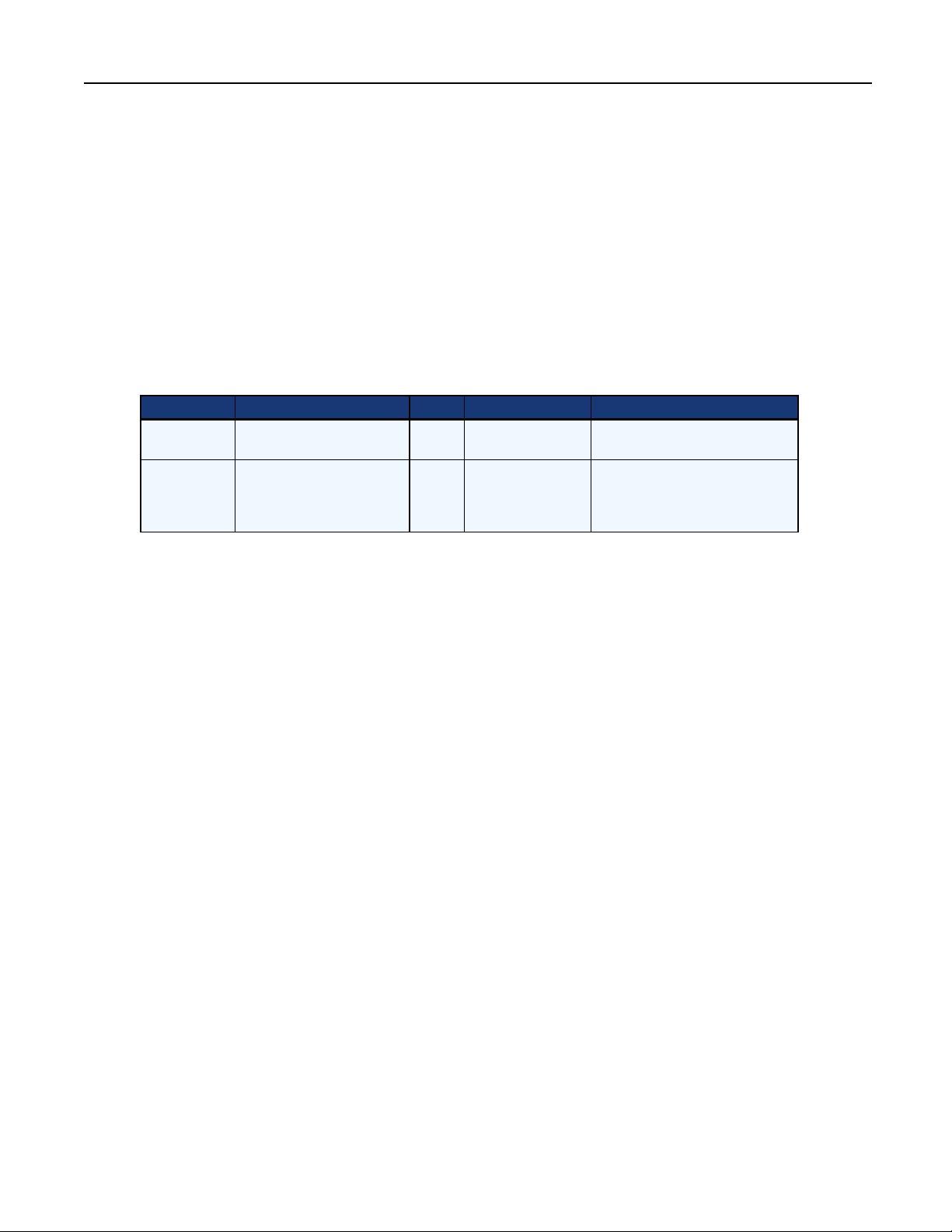
Table 2.1: Minimum System Recommendations
Recommended CPU Memory I/O Comments
Minimum
Recommended
Processor: Single core
Pentium 4, Speed: 2.8 GHz
Processor: Quad core Intel
Xeon processor, 4MB cache,
Speed: 2 GHz or greater
2GB
4GB or
greater
Standard desktop
configuration
SATA class I/O
consistent with
RAID5 using 7200
rpm drives
Chapter 2: Software Requirements 7
Application Server and DBMS on
separate machines. Hardware
requirements are identical for both.
Hardware considerations
While the hardware described provides satisfactory performance for day-to-day operation of the software, some
operations that are I/O intensive, such as importing and exporting Microsoft Excel representations of large floor
plans, can take a considerable amount of time directly related to I/O and CPU characteristics of the application
server and the database server.
Large floor plan imports and exports times can be reduced up to 50% by using faster CPU’s and I/O. Since
imports and exports are considered infrequent events in the daily use, the sizing recommendations are determined
based on the regular day-to-day use for building floor plans, device racks and creating future projects with
capacity planning.
Tuning considerations
In addition to the impact of hardware configuration, adjustments may be necessary to take advantage of
additional memory in either the application server or database server.
Application server
The application server memory is determined by parameters passed to the Java Virtual Machine (JVM) hosting
the Avocent Management Platform enterprise service bus. These settings are set to provide optimum performance
for the application and should not be adjusted.
Database server
PostgreSQL
The PostgreSQL Server can be tuned to take advantage of additional memory by modifying the postgresql.conf
file, which is located in the C:\Program Files\PostgreSQL\8.2\data\ directory for Microsoft Windows or in
Page 18

8 Data Center Planner Installer/User Guide
/var/lib/pgsql/data/ for Red Hat Linux installations.
For a new installation, the directory for Microsoft Windows is C:\Program Files\PostgreSQL\8.4.2\data\ or in
opt/PostgreSQL/8.4.2/data/ for Red Hat Linux.
Two configuration variables may be set in that file:
• The shared_buffers variable sets the amount of memory cache used by all PostgreSQL processes. It should be
set to 10-25% of total memory available to the database server.
• The following example is from the postgresql.conf file that is configured to reserve 2GB of memory. Please
note that changes in this file require restarting the database to take effect.
Resource usage (except WAL)
Memory - shared_buffers = 2GB min 128kB or max_connections at 16kB (This change requires a restart.)
The effective cache size is the amount of kernel cache that can be dedicated to PostgreSQL. Setting this depends
on what else is running on the machine. For a dedicated machine, set this to 75% of total memory.
Query tuning
Planner method configuration
• enable_bitmapscan = on
• enable_hashagg = on
• enable_hashjoin = on
• enable_indexscan = on
• enable_mergejoin = on
• enable_nestloop = on
• enable_seqscan = on
• enable_sort = on
• enable_tidscan = on
Planner cost constants
• seq_page_cost = 1.0 measured on an arbitrary scale
• random_page_cost = 4.0 same scale as above
• cpu_tuple_cost = 0.01 same scale as above
• cpu_index_tuple_cost = 0.005 same scale as above
• cpu_operator_cost = 0.0025 same scale as above
• effective_cache_size = 6GB
Microsoft SQL Server 2005
The default memory settings for Microsoft SQL Server 2005 are usually more than adequate. If you have other
applications installed on the server machine and wish to change the default settings, adjustments may be made
by using the MS SQL Server management studio application.
Page 19

Chapter 2: Software Requirements 9
Configuring SQL Server’s tempdb
The SQL Server tempdb system database is a global resource that is available to all users connected to an
instance of SQL Server. It is used to hold temporary and internal objects that SQL Server uses to perform many
different operations.
Performance issues
Because tempdb is used by all databases contained in an instance of SQL Server, it can become a bottleneck for
performance. It can also cause degraded performance if a single database continues to grow at a fast pace. In both
of these cases, tempdb automatically grows in size. The result is overhead during the execution of queries,
updates and other operations.
Determining the appropriate size
It is recommended that the initial size of tempdb be set to 25% of the total user database size. For example, if an
instance of SQL Server instance 3 databases of size 250mb, 250mb and 500mb, then the size of tempdb should
be calculated as: (250 + 250 + 500) / 4 = 250. Thus, the initial size of tempdb should be set to 250mb in this
case.
To set the initial size of the tempdb:
The initial size of tempdb can be set in two ways.
1. The first way requires Microsoft SQL Server Management Studio.
a. Connect to the SQL Server instance for which you desire to change tempdb size.
b. Select the instance’s node in the Object Explorer panel.
c. Select the Databases node and the System Databases node under that.
d. Right-click the tempdb node and select Properties.
e. In the dialog box that appears, select the Files tab.
f. Modify the Initial Size (MB) value for “tempdev” in the Database Files table. Set to the value described
in the above Determining the Appropriate Size section.
g. Click OK.
2. Set the initial size of tempdb is by executing the following SQL queries:
a. Get the current size of tempdb:
USE tempdb
GO
EXEC SP_SPACEUSED;
GO
b. Set the desired size of tempdb:
USE master
GO
ALTER DATABASE tempdb
Page 20

10 Data Center Planner Installer/User Guide
MODIFY FILE (NAME = ‘tempdev’, SIZE = 250MB);
GO
Page 21
Installation
3
Installing Data Center Planner
The following steps take you through the Data Center Planner installation process.
NOTE: Data Center Planner does not support network drive installations. T he software must be installed on a hard drive partition. In
addition, the installation isnot supported on a domain controller. It must be installed on a system with a properly configured hostname,
which resolvesto the IP address of the server where the application is installed.
To install the application on a Windows machine, run the DataCenterPlanner.exe, or on a Linux
machine, run the DataCenterPlanner.bin.
11
1. The Install Anywhere window launches. This may take several minutes.
2. On the first screen, select a language from the drop-down list. Click OK.
3. On the Data Center Planner Introduction screen, click Next.
4. Accept the Data Center Planner license agreement, and click Next. The Choose Install folder screen opens. On
a Linux machine, the path is /usr/local.
5. Accept the Data Center Planner default location folder or choose another location. Click Next.
6. A Database Installation Warning opens advising not to choose Oracle® as a database selection. Click OK.
7. On the Data Center Planner Pre-Installation Summary screen, click Install. This may take several minutes.
8. In the meantime, the Avocent Management Platform (AMP) installation begins. On the AMP Introduction
screen, click Next.
9. Accept the AMP license agreement, and click Next.
10. Accept the AMP default location folder or choose another location. Click Next.
11. Enter an AMP default administrator username and password. Confirm the password, and click Next.
12. On the AMP Database Selection screen, there are four options for installing a database:
a. Install a new PostgreSQL database.
• On the PostgreSQL Database installation screen, enter a password, confirm the password, and click
Next. Be sure to note the password for editing in PostgreSQL.
• On the Pre-Installation Summary screen, click Install.
b. Connect to existing PostgreSQL database.
c. Connect to existing Oracle database. (Oracle database is not supported for use with Data Center
Planner. If you choose this database, the installation will not perform properly.)
d. Connect to existing Microsoft SQL Server database.
Page 22

12 Data Center Planner Installer/User Guide
• On the Existing Microsoft SQL Server Database Configuration screen, enter the database server,
database name, username and password. Check the Use Unicode Encoding checkbox if required,
and click Install.
NOTE: When selecting Microsoft SQL, a domain name is required, use Username:domain\username. An instance name is not
required, but you can use MS-SQL-ServerName\InstanceName.
13. It may take several minutes for the database to load.
14. When the AMP installation is complete, click Done.
15. The Data Center Planner installation continues.
16. A message displays advising to wait for the Data Center Planner services to come up before launching the
application. Click OK, then click Done.
17. To run the application on a Windows Server, go to Start - All Programs - Avocent - MergePoint Data
Center Planner - Avocent - MergePoint Data Center Planner. On a Linux machine, open a browser and
point the server where the application was installed.
18. Depending on your browser, a message may appear advising that there is a problem with the web site
security certificate. Follow the instructions for installing the browser's security certificate.
19. Next, activate the license to use the application. If the proper license is not activated, you will be unable to
manage floor plans. The following errors may occur: the launch site does not display or the launch site
displays the correct information under Start - All Programs but no plans can be created, deleted, loaded or
imported.
20. After activating the license, create users.
NOTE: You can also access the application from any supported web browser with access to the installed server. The URL is https://
{servername}:8443/console/console.html?root=mergepoint, where {servername} is replaced with the name or IP address of the
server upon which the application was installed.
NOTE: When first logging in,if the application doesnot open with the username and password fields, close the browser and wait a
few minutes for the database information to load and servicesto start, then try again. F or more information on stopping and starting
the services, see Stopping and Starting the Avocent Services on page 142
Installing Data Center Planner on a server with limited or no Internet
connection
To install the software with limited or no internet connectivity:
To activate the software on a brown or black site, contact your Technical Support. They will need the host name
of the server. They will send you an email with information to activate your software.
Logging into Data Center Planner
A user with roles and rights must be created before using the application. An administrator must create users and
assign roles.
To log into Data Center Planner:
1. Select Start - All Programs - Avocent - MergePoint Data Center Planner - Avocent MergePoint Data Center
Planner.
Page 23

Chapter 3: Installation 13
2. Enter the username and password created in user management by the administrator.
3. Click Options to expand all options. Leave the default Authentication Source as Internal.
4. Enable the Remember User checkbox if you want the system to remember your log in information.
5. Click Change Password if you want to change your password.
a. Enter your Username.
b. Enter your old password.
c. Enter a new password.
d. Confirm the new password by entering it again.
e. Click OK.
6. Click Login or press Enter.
7. The application opens to a dialog box with the list of available plans. Depending on your rights, you may
or may not have Create Plan and Import Plan as options.
NOTE: If you clickCancel on this dialog box, you cannot place anything on the content area or export a plan.
8. Select a floor plan from the list and click Open or select Create Plan or Import Plan.
9. When a floor plan opens, the application is in current state mode. Depending on your rights, current state,
project or history modes are functional accordingly.
Migrating to a New Version of Data Center Planner
Before upgrading to a new version:
1. As a safety precaution, before migrating to a new version, you must backup the database and floor plans.
2. Check to make sure your maintenance agreement is up to date.
3. Check to make sure your hardware and software are up to date.
4. Do not uninstall the software before migrating to a new version. If you do so, you will lose your projects
and your database.
5. When a new version is released, you will receive an email with a link to the location for downloading the
software and documentation.
6. When you run the executable, it will automatically replace your version, and your current plans will be
transferred to the new version.
To migrate to a new version:
1. Run DataCenterPlaner.exe or on a Linux machine, run the DataCenterPlanner.bin.
2. The Install Anywhere window launches. This may take several minutes.
3. On the first screen select a language and click OK.
4. Click Next on the Introduction screen.
5. Accept the License Agreement, and click Next.
Page 24

14 Data Center Planner Installer/User Guide
6. Accept the default location on the Choose Install Folder screen, and click Next. On a Linux machine, the
path will be different.
7. Accept the default on the Installation Upgrade screen, and click Next.
8. On the Pre-Installation Summary screen, click Install. This may take several minutes.
9. Click Done when the installation is complete.
10. Click OK on the Install Complete message. Please allow approximately 30 minutes for the services to come
up before launching the application. Please do not restart the server during this time.
11. Once the database has migrated, import all floor plans again, then you can remove the older versions.
NOTE: When first logging in,if the application doesnot open with the username and password fields, close the browser and wait a
few minutes for the database information to load and servicesto start, then try again.
Uninstalling Data Center Planner
It is not necessary to uninstall the application before migrating to a new version. If you do uninstall, you will
lose your projects, plans and your database. Be sure to backup your database, export your projects to .pdf files
for reference and export your plans to spreadsheets.
To uninstall Data Center Planner and Avocent Management Platform (AMP) on a Windows machine:
NOTE: If you uninstallAMP, you may remove other Avocent products that are installed on your system.
1. Select Start - All Programs - Avocent - MergePoint Data Center Planner - Uninstall. The Uninstall
Introduction screen opens. Click Uninstall. Click Done when complete.
2. If you desire to remove the AMP program, go to Start - Control Panel - Add or Remove programs and
Remove the Avocent Management Platform program. Click Uninstall, then click Done.
3. If you desire to remove the database, highlight PostgreSQL and click Remove the PostgreSQL.
4. After removing the database from your control panel, navigate to C:\Program Files and delete the
PostgreSQL folder.
5. Under Program Files also delete the Avocent folder, then navigate to C:\Documents and Settings and delete
the Postgres folder.
6. Go to My Computer, right-click and select Manage.
7. Expand Local Users and Groups, and select Users. Delete the postgres user.
8. Go to Start - Control Panel - System and click the Advanced tab.
9. Click Environment Variables.
10. Under System Variables, highlight DVR_HOME, and click Delete.
11. Highlight AMP_HOME, and click Delete.
12. Reboot your computer.
To uninstall on a Linux machine:
1. Right-click on the desktop and select Open Terminal.
2. At the # prompt, enter cd $DVR_HOME. Press Enter.
3. Enter cd Uninstall. Press Enter.
Page 25

Chapter 3: Installation 15
4. Enter ./Uninstall_Data_Center_Planner. Press Enter.
5. Enter cd $AMP_HOME. Press Enter.
6. Enter cd uninstall. Press Enter.
7. Enter ./Uninstall_AMP. Press Enter.
To remove the PostgreSQL 8.2 application packages:
1. At the prompt, enter rpm -qa /grep -i postgres. Press Enter to view the packages.
2. Enter rpm -e <packagename>. Press Enter to delete the packages.
To remove the PostgreSQL 8.4.2 application packages:
1. At the prompt, enter cd /opt/PostgreSQL/8.4.2/
2. Enter ./install-postgresql. Click Yes.
To remove the Postgres database 8.2 folder:
1. At the prompt, enter cd /var/lib. Press Enter.
2. Enter rm -rf pgsql. Press Enter.
To remove the Postgres database 8.4.2 folder:
1. At the prompt, enter cd /opt/. Press Enter.
2. Enter rm -rf /opt/PostgreSQL/. Press Enter.
To cleanup and remove the Avocent folder:
1. At the prompt, enter cd /usr/local. Press Enter.
2. Enter rm -rf Avocent. Press Enter.
To remove the Avocent xml file:
1. At the prompt, enter cd /opt. Press Enter.
2. Enter rm -rf Avocent. Press Enter.
NOTE: When uninstalling Avocent Management Platform, you may receive the following message: D:\Avocent\docsrefers to a
locationthat is unavailable. It could be on a hard drive on this computer or on a network. Check to make sure that the disk is properly
inserted, or that you are connected to the Internet or your network, and then try again. If it stillcannot be located, the information might
have been moved to a different location. This is a Windows Explorer refreshing issue. On the left side of the panel, it looks like the
directories are still there. However, unless there is a file that was not removed from the selected directory, Windows willdisplaythe
message that the selected directory refers to a location that is unavailable because the selected directory was deleted. ClickOK on the
message and itwill refresh and show the remaining directories.
If an uninstall fails on a Microsoft Windows machine, use the following steps to uninstall the
software:
1. Uninstall AMP.
2. Start Windows Explorer.
3. Remove the directory where Avocent Management Platform and Data Center Planner were installed.
Page 26

16 Data Center Planner Installer/User Guide
4. Go to Start - Run.
5. Enter regedit.
6. Expand HKEY_LOCAL_MACHINE - Software - Microsoft - Windows - CurrentVersion - Uninstall.
7. Remove Data Center Planner and Avocent Management Platform, if they exist.
If an uninstall fails on a Linux machine, use the following steps to uninstall the software:
1. From the Linux terminal, enter cd $AMP_HOME/uninstall. Press Enter.
2. Enter ./Uninstall_AMP. Press Enter.
3. Enter cd /home. Press Enter.
4. Enter rm -rf <top level of the directory where AMP and DVR were installed>. Press Enter.
5. Enter rm -rf /etc/profile.d/amp.sh. Press Enter.
6. Enter rm - rf /etc/profile.d/dvr.sh. Press Enter.
Page 27

User Management
4
Managing Users
Before using Data Center Planner, an administrator must create users and assign roles to users. Data Center Planner
utilizes existing and custom authentication methods to create and authorize new users and establish roles and
effective rights.
The administrator does not have rights for any other part of the application. They can only log into the application
and select User Management and Licensing to manage users and activate licenses unless other rights are assigned.
Authentication
17
Internal authentication is configured automatically when the Avocent Management Platform is installed.
External Authentication
Data Center Planner also allows External Authentication and Authorization through LDAP and Active Directory.
External authentication is based on plugging in external services to the Authentication Manager. All instance
creation is managed using the configuration console. The Avocent server authenticates to the actual external
authentication service when doing instance creation. If you can normally authenticate to a service, the same rights
should be adequate for creating an external authentication instance using the Avocent server. For additional
information, see External Authentication and Authorization on page 137.
Users
These options are used to manage users, groups and external group mappings.
Permissions
Permissions are a relationship between a user and a role. A role is a set of rights and targets.
Rights
For a role to be effective, it must have a right. A role can be created without targets, and it can be assigned to users,
groups and collections.
The following descriptions are default roles that can be assigned to a user and the rights assigned to them. For
additional information, see Roles on page 20.
• User - Persons authenticated with access to the authorization system. Only the unique identifier of the person is
stored.
• Effective Rights - Used to identify the effective rights for users, rights and targets.
• Permission - An unnamed association of a user and role.
Page 28

18 Data Center Planner Installer/User Guide
• Role - A set of rights used in conjunction with a user and a target to create permissions. Each role has a
unique name within the system.
• Groups - Groups can be created and users assigned to a group or groups.
The current roles are:
Avocent Administrator - Performs user management functions only, such as add, assign and edit users,
permissions and roles.
Data Center Planner-Executor - Can perform the same functions as a read-only user and commit tasks within a
project.
Data Center Planner-Manager - Has read-write permissions.
Data Center Planner-Planner - Can perform the same functions as read-only users, plus view, edit and create
projects. The planner role does not have access to import, create or delete current floor plans.
NOTE: A planner can only create templatesin the context of a project. Unlike the manipulation of assets and their properties in project
planning, the templates created by a planner are available across all floor plans and time and can be used by anyone in the current
state, providing they have permissions.
Data Center Planner Project Review - Can perform the same functions as read-only users plus view projects and
history but cannot create or make changes to current floor plans or projects. A project reviewer can click the
Revalidate button to refresh a project making sure the project is current.
Data Center Planner - ReadOnly - Can open global view, view floor plans, racks, assets, connections and history,
but cannot make changes in any view.
Reporting Designer - Can create reports using Crystal Reports.
Reporting Viewer - Can view reports.
Creating Users
To create new users:
1. Log in as an administrator and select User Management from the primary navigation panel.
2. Select Users from the secondary navigation panel.
3. Select New from the Actions, Users pane.
4. Enter a username. Do not use any spaces in the username.
5. Enter a password. The password should be between 8 and 65 characters, contain at least one alphabetic and
one numeric character and contain at least one upper case and one lower case letter, then confirm the
password by entering it again.
6. To assign the new user to a group, select Groups from the left tree.
7. Select a group from the Available groups column, click on a group, then click the right arrow to move it to
the Selected groups column, and click OK.
8. To assign the new user account information, select Properties from the left tree.
9. Enable the appropriate boxes, add an expiration date if necessary, and click OK. The new user is added to
the list of users.
10. Select Permissions from the secondary navigation panel to assign the new user a role.
Page 29

Chapter 4: User Management 19
11. Under the Permissions pane, expand the AllUsers option.
12. Click on the new user just created.
13. Under Actions, Roles, click Assign Role.
14. From the Available roles column, click on a role, then click the right arrow to move the role to the Selected
roles column.
15. Click OK. The new role is added to the Roles, Assigned column.
16. Click User in the left, and on the bottom of the content screen, you can enter contact information for the
user.
To add a group and assign users to groups:
1. Select Users from content panel.
2. Select New Group from Actions, User, Groups pane.
3. Enter a name for the new group.
4. In the Available users column, click the desired users to add to the new group, then click the right arrow to
move the users to the Selected users column.
5. Click OK. The new group is added to the Groups column.
NOTE: The application supports using specialcharacters when naming groups. Use Active Directory naming conventions, such as
alphabeticalcharacters (Aa-Zz), numeric characters (0-9) , the minussign "-" and the period ".". Do not include spaces, ampersand,
more than/less than brackets, slashes, colon or semi-colon (&,<>, /, :,;).
Changing a password
There are two ways to change a password:
• An administrator can change a password in the User Management menu under Users.
• A user other than an administrator can use the login options.
To change a password by using the log in options:
1. You must be logged out of the application.
2. On the log in screen, click Options to expand all options.
3. Click Change Password.
a. Enter your username.
b. Enter your old password.
c. Enter a new password, then confirm the new password by entering it again. Click OK.
4. Log in with the new password.
To change a password by using the administrator log in:
1. Log into User Management.
2. Select Users from the secondary navigation panel.
3. Click AllUsers under the Groups column.
Page 30

20 Data Center Planner Installer/User Guide
4. Select a user under the User name column.
5. Click Edit under User in the Actions column.
6. Click Change Password.
7. Enter a new password.
8. Confirm the new password. Click OK.
9. The Change password was successful message opens. Click OK.
Roles
Roles are managed from User Management in the primary menu, are related to permissions and contain rights,
collection and targets associations.
To add a role:
1. Select User Management from the primary menu.
2. Click Permissions in the secondary menu.
3. In the lower pane, under Roles Management, Actions, select New.
4. Enter a name for the new role in the name field.
5. Click Available Rights in the left tree.
6. Expand the Avocent Data Center Management option.
7. Expand the appropriate option for Collection, Project or Plan.
8. Enable the appropriate boxes to assign to the new role, and click OK.
9. The associated rights are displayed in the Rights column.
To edit a role:
The Avocent Administrator role cannot be edited.
1. Select the role to be edited, and click Edit under Actions.
2. Change the name or click Available Rights in the left tree.
3. Expand the Avocent Data Center Management option.
4. Expand the appropriate option for Collection, Project or Plan.
5. Enable or disable the appropriate boxes to edit the role, and click OK.
6. The new associated rights are displayed in the Rights column.
To delete a role:
The Avocent Administrator role cannot be deleted.
1. Select the role to be deleted, and click Delete under Actions.
2. A confirmation message displays. Click Yes to delete the role.
To copy a role:
1. Select the role to be copied, and click Copy under Actions.
Page 31

2. Change the name and click Available Rights in the left tree.
3. Expand the Avocent Data Center Management option.
4. Expand the appropriate option for Collection, Project or Plan.
5. Enable or disable the appropriate boxes to edit the role, and click OK.
6. The new associated rights are displayed in the Rights column.
Chapter 4: User Management 21
Page 32

22 Data Center Planner Installer/User Guide
Page 33

Licenses
5
Rack Licensing
The application licensing is on a per rack basis. For example, a 100-rack license allows you to define 100 racks
across all floor plans. Defining a total number of racks that exceeds your application license will create a
notification pop-up at each subsequent log in.
The maintenance licensing provides access to application and shape database maintenance upgrades for the term of
the maintenance license.
License enforcement
23
You can apply a production license that has a purchased rack count against it. The application will give visual
feedback on the number of racks in plans and how many are licensed.
At log in, once the total plans reach the licensed rack count, the application starts informing you that you have
exceeded the rack count. It will not allow you to place any racks beyond the licensed count. This includes copy
and paste of racks and through any use of the web service interface or import.
License activation
After installing the software, you must activate the license.
To activate a license:
1. After logging into the application, select Licenses from the primary navigation panel.
2. Select Licenses from the secondary navigation panel.
3. From the Actions, Licenses pane, select Activate.
4. Enter your Entitlement ID, and click Get Entitlement.
5. In the table, on the Data Center Planner Maintenance line, enter the number of maintenance licenses to be
activated in the Copies to activate column.
6. On the Data Center Planner line, enter the number of racks to be activated.
7. The number of licenses/racks activated will be subtracted from the total number purchased in the Copies
remaining column.
8. Click Activate.
Off-Line License Activation
If you install Data Center Planner install on a protected network, and it is not able to communicate with our
licensing servers on the Internet, you will have to perform off-line license activation. Please let your sales team
Page 34

24 Data Center Planner Installer/User Guide
know that you require this type of license activation.
You will provide your sales team with the hostname of the server where Data Center Planner will be installed. A
license certificate will be generated with that host name and sent to you by email before you start the
installation.
To perform an off-line activation after receiving the .lic file:
1. Microsoft Windows:
• Place the .lic file in the [AMP_HOME]\bin.
• Refresh the license server by running the lmreread.exe in the same folder.
2. Red Hat Linux Enterprise:
• Place the .lic file in the [AMP_HOME]\bin.
• Refresh the license server by running the lmreread in the same folder.
License return
Rehosting is the administrative process of issuing a return of license activations for a device that is going to be
decommissioned followed by an entitlement and activation of the same licenses on a different computer.
If you need to rehost entitlements to another computer, have the entitlement ID and activation ID and work with
Avocent customer Support or Professional Services. To rehost licenses so the rehosting does not count as the one
return that can be done within the rehost licenses policy.
License repair
The licensing is anchored to a single machine and synchronized to the server clock. Changes to the device setup,
clock changes or alterations to files within the server may cause corruption preventing licensing from performing
appropriate. Licensing will attempt to repair this automatically. Should licensing fail to operation and log files
indicate that the license cannot be repaired, please contact Avocent support.
License details
You can display your license information by clicking on Details in the Action panel.
Proxy settings
You only have to set up a proxy server if your environment has a firewall that blocks communication to the
Avocent licensing server. To use a proxy server, you must know the proxy server address and port. If the proxy
server requires credentials to log in, you must have an associated username, password, and domain.
To use a proxy server with licensing:
1. In the Licenses menu, click Proxy in the Actions pane.
2. When the Proxy settings dialog opens:
• Enable Use proxy server.
• Enter the proxy server's IP Address or DNS Name.
• Enter the Port number.
Page 35

Chapter 5: Licenses 25
• Enter a User name and Password,
• For proxy servers requiring Microsoft domain authentication, enter the name of the domain in the
Domain field.
3. Click the OK button. The message: “Proxy settings successful” will be displayed. This success message only
indicates that the proxy information has been stored. It does not verify that the proxy information is correct.
If the information entered is incorrect, activation may fail.
Page 36

26 Data Center Planner Installer/User Guide
Page 37

Integration with other Emerson Network
27
6
Power Products
Supported Products
Data Center Planner supports integration capability with three Emerson Network Power products concurrently.
DSView™ management software
Avocent DSView software provides data centers with secure, centralized management for physical and virtual IT
assets. By allowing administrators to remotely diagnose and modify any managed device, regardless of the health or
status of the operating system or network connection, DSView software makes data center management and remote
offices more accessible, extensible and secure.
DSView software easily integrates with existing security infrastructure, authenticating against internal or external
standards-based services. All traffic is encrypted and the detailed activity logs provide a critical audit trail for issue
resolution and regulatory compliance. Remote management capabilities allow physical lock down of sensitive
machines. To take advantage of DSView software functionality, you must purchase a software web services license.
NOTE: All instances of DSView software within this document refer to DSView software versions 3 or higher.
Rack Power Manager
Rack Power Manager software is a stand-alone web browser-based, centralized rack power distribution unit (PDU)
management solution. It provides all centralized management capabilities related to rack PDU devices, can perform
power control actions and can run power consumption reports for rack PDUs.
Liebert SiteScan™ web software
Liebert SiteScan Web software uses a network of microprocessor-based control modules to monitor and control
Liebert precision cooling, power, UPS and other critical equipment. It enables the user to monitor and control
equipment in a single building, an entire campus or a network of facilities around the globe.
A Liebert SiteScan Web system utilizes a web-based server running Microsoft Windows XP, 2003 Server or 2000
and a conventional web browser to gather information, change operating parameters, run reports and perform similar
functions on various types of critical equipment.
Integrating with Data Center Planner
DSView software integration
Data Center Planner allows direct access to assets being managed by the DSView software by opening a web
service session with the DSView software. For additional information on this capability, see DSView Software
Page 38

28 Data Center Planner Installer/User Guide
Managed Assets on page 103.
Data Center Planner can retrieve real world power readings for PDUs that are being managed by the DSView
software via the web server interface with the DSView software. For additional information, see Real world
power on page 105.
In order to prepare Data Center Planner for integration with DSView, the administrator must first import the
DSView software certificate to Data Center Planner as described in Importing Certificates on page 29; then the
DSView software connection properties can be established using the following steps.
NOTE: In order to enable web session operation with Data Center Planner, a DSView Web Services API license must be purchased
and installed on the DSView software server.
To configure DSView software connection properties:
1. Launch the application. You must have a floor plan open to configure DSView software devices.
2. Select Edit, DSView™ Software Configuration from the menu options.
3. Enter the Server Host name.
4. Enter the Server Port.
5. Enter the Service Account name.
6. Enter the Service Account password.
7. Click Test to test the connection.
8. If the test is successful, click Save.
Rack Power Manager integration
Data Center Planner can retrieve real world power readings for PDUs that are being managed by the Rack Power
Manager software via the web server interface with Rack Power Manager software. For additional information,
see Real world power on page 105
In order to prepare Data Center Planner for integration with Rack Power Manager software, the administrator
must first import the Rack Power Manager software certificate to Data Center Planner as described in Importing
Certificates on page 29, then the Rack Power Manager software connection properties can be established using
the following steps.
NOTE: In order to enable web session operation with Data Center Planner, a Rack Power Manager API licensemust be purchased
and installed on the Rack Power Manager software server.
To configure Rack Power Manager software connection properties:
1. Launch the application. You must have a floor plan open to configure Rack Power Manager software
devices.
2. From the Edit menu, select Rack Power Manager Software Configurations.
3. Enter the Server Host name.
4. Enter the Server Port.
5. Enter the Service Account name.
6. Enter the Service Account password.
Page 39

Chapter 6: Integration with other Emerson Network Power Products 29
7. Click Test to test the connection.
8. If the test is successful, click Save.
Liebert SiteScan™ Web integration
Data Center Planner can retrieve real world power readings for PDUs that are being managed by the Liebert
SiteScan Web software via the web server interface with Liebert SiteScan Web. For additional information, see
Real world power on page 105.
In order to prepare Data Center Planner for this integration with Liebert SiteScan Web, there is one action that
must be performed by the administrator. The Liebert SiteScan Web software connection properties must be
established using the following steps.
To configure Liebert SiteScan Web software connection properties:
1. Launch the application. You must have a floor plan open to configure Liebert SiteScan Web software
devices.
2. From the Edit menu, select Liebert SiteScan Web Configuration.
3. Enter the Server Host name.
4. Enter the Server Port.
5. Enter the Service Account name.
6. Enter the Service Account password.
7. Click Test to test the connection.
8. If the test is successful, click Save.
Importing Certificates
In order for DSView and Rack Power Manager software to interface with Data Center Planner, it is necessary to
import the software certificate to the Avocent® Management Platform/Data Center Planner server. This trust
relationship is needed so that the client server (Data Center Planner) will trust the DSView management software
or Rack Power Manager software server and establish a secure connection. Both DSView management and Rack
Power Manager software use the same process for handling certificates.
NOTE: It is not necessary to import the software certificate for Liebert SiteScan™ Web software.
When importing a certificate on a Windows server, if you get an Access Denied error, right-click the command
prompt on the server and click Run as Administrator. This will let you enter the command and import the
certificate with no errors.
To import software certificates:
1. Open a browser on the Data Center Planner server and connect to the server.
• For DSView software, use https://<dsview server>.
• For Rack Power Manager use, https://<rpm server>.
2. The browser displays the Certificate Error next to the address bar. Click Certificate Error.
3. When the Certificate Invalid window opens, click View certificates at the bottom of the window.
Page 40

30 Data Center Planner Installer/User Guide
4. Click the Details tab, then click the Copy To File... button. Click Next.
5. Select Base-64 encoded X.509 (.CER). Click Next.
6. Enter dsview or rackpower as the file name, then click the Browse button.
7. Select the root of the C: drive as the location to save the file. This should always be the default location.
8. Click Next and Finish.
To import a certificate to the Avocent Management Platform (AMP) trust store:
From the command prompt, execute the following (single) command. Type the command exactly as shown in the
following DSView software example, replacing "aliasname" with a unique name for DSView management and
Rack Power Manager software.
"%AMP_HOME%"\jre\bin\keytool -importcert -alias aliasname -storepass changeit -keystore
"%AMP_HOME%"\jre\lib\security\cacerts -file c:\dsview.cer"
On successful execution of the command, the user is prompted for: Trust this certificate?: Enter yes and click
Enter.
NOTE: For best results, manuallytype in the command. There may be a for matting issue with copy and paste for hyphens and
quotes.
To import a certificate on a Linux machine:
From the terminal, execute the following (single) command. Type the command exactly as shown.
$AMP_HOME/jre/bin/keytool -importcert -alias aliasname -storepass changeit -keystore
$AMP_HOME/jre/lib/security/cacerts -file /root/Desktop/dsview.cer.
To delete an existing certificate from the AMP trust store:
From the Command Prompt, execute the following (single) command, where aliasname is the alias name of the
certificate that is to be deleted.
"%AMP_HOME%"\jre\bin\keytool -delete -alias aliasname -storepass changeit -keystore
"%AMP_HOME%"\jre\lib\security\cacerts
To view the existing certificate stored in the AMP trust store:
From the Command Prompt execute the following (single) command, where filename is the file name of the
certificate with the complete path.
"%AMP_HOME%"\jre\bin\keytool -printcert -file filename -storepass changeit -keystore
"%AMP_HOME%"\jre\lib\security\cacerts
Page 41

Collection Management
7
Collection Management allows Data Center Planner to restrict users access to specified plans and assets.
Administrators can select plans and floor-mounted assets to create a new collection and assign it a role with write
or read-only rights, so that the user can access plans and floor-mounted assets appropriately.
The Collection Management feature is disabled by default and can only be enabled by the server administrator
where Data Center Planner is installed using the following steps. When the server administrator enables the
collections feature, the Data Center Planner administrator can then create collections.
NOTE: The Collection Management tab isnot selectable if Collection Management is disabled or if the logged in user does not havethe
appropriate rights.
31
To enable Collection Management:
1. The server administrator must edit the following file: \[AMP_HOME]\conf\extention.xml using a text file
editor.
2. In the text file editor, locate the line containing the text "<target name="AccessControl">".
3. Edit the next line containing text "<property name="isEnabled" value="".
4. Change the text to value="true" to enable.
5. Restart the application for the change to take effect.
6. To disable, change the text to value="false" and restart the application. It is recommended to leave this feature
disabled if no collections are needed.
Collection Access Control
The following table describes access control in Collection Management.
Table 7.1: Collections Access Control Descriptions
Access to Description
PlansOpen/Copy/Delete/Save
Floor-mounted assets
Inventory/Capacity
search
Capacities
Show asset labels You can only use the Show Asset Labels option for plansand assetsfor which you have access.
With the accesscontrol function, you can only view plansfor which you have accessrights.
To accessfloor-mounted assets in a plan, you must be assigned right accessto the plan and based on this plan,
you must be assigned access to the selected floor-mounted assets.When you open one plan, allfloor-mounted
assetsare listed, but you can onlyaccessassetsfor which youhave rights. If some assets in planare not
controlled by right access, that asset can be accessed by anyone who hasplan rights.
You can only search for plans for which you have rights. If you have access to a plan, you may not have accessto
allof the assets in that plan.
If you cannot access any assets in the plan, then capacitiescannot be computed or shown in colors. If you have
accessto specific assets, then capacitiesare computed and shown in color for those assets.
Page 42

32 Data Center Planner Installer/User Guide
Access to Description
Import/Export to/from
.xlsfile
You can only use the import or export feature for plansand assetsfor which you have access.
Creating Collections
To create a new collection:
1. Log in as an administrator and select Collection management from the primary navigation panel.
2. Select New in the Collection Management, Actions column.
-or-
Select the down arrow next to Collection Management from the primary navigation pane and select
New. The New Collection dialog displays with a list of current plans and their floor-mounted assets.
3. Enter a name a description.
4. Click the down arrow on a plan to view the floor-mounted assets. Enable the appropriate checkboxes to
associate with the new collection, and click OK.
5. Note that the plan and floor-mounted assets columns show the information associated with the new
collection.
To assign access control to a collection to a role:
1. Select a role from the bottom Roles column to associate with the collection, then select Read Only or Write
from the Actions pane.
-or-
Select the down arrow next to Access Control to Collections, and select Assign Read Only or Assign
Write. The Assign Collections dialog displays with a list of available collections.
2. Enable the desired collection, and click OK.
NOTE: It is not recommended to assign a collection to an existing role that has already been assigned to users pr ior to using the
Collection Management feature. This includes the current roles provided by Data Center Planner, Data Center Planner Manager or
Reporting Designing. A new role should be created which is then associated with a defined collection. If a new user isbeing created,
then the user can be assigned the appropriate roles. If the administrator wants to restrict access of an existing user to certain assets
within plans using CollectionsManagement, the administrator must edit the assigned rights of that user. The roles currently assigned
to that user should be removed and the new roles with the associated collections be assigned.
To edit a collection:
1. Select the collection to be edited, and select Edit in the Collection Management, Actions column. The Edit
Collection dialog displays with a list of current plans and their floor-mounted assets associated with the
collection.
-or-
Select the down arrow next to Collection Management in the top pane, and select Edit.
2. Disable or enable the appropriate plan or floor-mounted asset, and click OK.
3. Note that the plan and floor-mounted assets columns show the information associated with the edited
collection.
Page 43

Chapter 7: Collection Management 33
To delete a collection:
1. Select the collection to be deleted, and select Delete in the Collection Management, Actions column.
-or-
Select the down arrow next to Collection Management in the top pane, and select Delete.
2. A confirmation message displays. Click Yes to delete the collection.
Page 44

34 Data Center Planner Installer/User Guide
Page 45

Database Information
8
Connecting to an Existing PostgreSQL Database
This option allows you to connect to a PostgreSQL database that already exists on your system.
To connect to an existing PostgreSQL database using a Windows server:
1. On the Database Selection screen during the installation, select the Connect to existing PostgreSQL database
radio button and click Next. The Existing PostgreSQL Database Configuration screen opens. A new database
will be created at the location of the existing database.
2. Go to the system where the existing database is located and select Start - Programs - PostgreSQL - pgAdmin
III. The pgAdmin software opens.
35
3. In the tree, double-click PostgreSQL Database Server (localhost) to expand the directories.
4. Double-click Databases, right-click on AMPDB and select New Object - New Database. The New Database
dialog box opens.
5. Enter a name for the new database and in the Encoding field, select UTF8 from the drop-down list. This is
acceptable for both Window Server and Linux servers. Click OK. The new database is listed in the tree.
6. Select Start - PostgreSQL - Configuration files - Edit pg_hba.conf. The notepad opens.
7. Scroll to the bottom and locate #IPv4 local connections:
8. Go to the line host all all (IPlocalhost address) md5. Press Enter.
9. On the blank line, enter host all all 0.0.0.0/0 md5.
10. Select File - Save, then File - Exit and select Start - PostgreSQL - Configuration files - Edit postgresql.conf.
The notepad opens.
11. Select Edit - Find, enter localhost and click Find Next.
12. Under connections and authentication, delete the # in front of listen_addresses and change localhost to an
asterisk (*).
13. Select File - Save, then File- Exit.
14. Select Start - PostgreSQL - Stop service.
15. Select Start - PostgreSQL - Start service.
16. Exit the pgAdmin III software.
17. Close the system where the new database was created.
18. Go back to the Installation process at the Existing PostgreSQL Database Configuration screen and enter the
new database information.
• Database Server - Port number 5432 (default) - The system where the new database was created.
Page 46

36 Data Center Planner Installer/User Guide
• Database Name - Create a name.
• User Name - Enter postgres.
• Password - Enter the password created when AMP was first installed and click Next. The Pre-Installation
Summary screen opens. On a Linux machine, this screen will appear different.
19. Click Install. The installation begins. Upon completion, the Install Complete screen opens.
20. Click Done to complete the installation. See Installation on page 11.
To connect to an existing PostgreSQL database using a Linux server:
1. On the Database Selection screen during the installation, select the Connect to existing PostgreSQL
database radio button and click Next. The Existing PostgreSQL Database Configuration screen opens. A
new database will be created at the location of the existing database.
2. From a terminal window, enter createdb <database name> -U<postgres user>. A message displays
stating create database.
3. Enter psql -d<database name> -U<postgres user>.
4. At the prompt <database name>=# enter Alter <database name> set Encoding = 'UTF8'.
5. At the next prompt, enter \q. This takes you out of the Postgres application.
6. Go to the Postgres data directory where Postgres was installed, var/lib/pgsql/data for Postgres version 8.2, or
for a new installation, the directory is opt/PostgreSQL/8.4.2/data.
7. Enter vi pg-hba.conf.
8. Click the Insert key.
9. Scroll to the bottom and locate #IPv4 local connections:
10. Go to the line host all all (IPlocalhost address) trust and click Enter.
11. On the blank line, enter: host all all 0.0.0.0/0 trust
12. Press the Esc key, hold down the Shift key and click the : key.
13. Enter wq and click Enter.
14. Enter vi postgresql.conf
15. Under connections and authentication, delete the # in front of listen_addresses and change localhost to an
asterisk (*).
16. Click the Esc key, hold down the Shift key and click the : key.
17. Enter wq and click Enter.
18. Click System - Administration - Services.
19. Highlight posgresql and click Restart.
20. Exit from the Services Configuration by either clicking the (x) in the upper, right corner or File, Quit.
21. Close the system where the new database was created.
22. Go back to the installation process at the Existing PostgreSQL Database Configuration screen and enter the
new database information.
• Database Server - (Port number 5432, default) - The system where the new database was created.
• Database Name - Create a name.
Page 47

• User Name - Enter postgres.
• Password - Enter the password created when AMP was first installed and click Next. The Pre-Installation
Summary screen opens. On a Linux machine, this screen will appear different.
23. Click Install. The installation begins. Upon completion, the Install Complete screen opens.
24. Click Done to complete the installation.
25. Continue as instructed in the Installation section.
PostgreSQL 8.2 Database Backup
The following information describes the process for backing up and restoring the PostgreSQL database, version
8.2.
Backing up the PostgreSQL database with pg_dump
The idea behind the SQL-dump method is to generate a text file with SQL commands that, when fed back to the
server, will recreate the database in the same state as it was at the time of the dump.
To backup the database on a Windows server:
Chapter 8: Database Information 37
1. Stop the Avocent Management Platform ESB service by using one of the following steps:
2. Using the Windows server:
a. Go to Start, Control Panel, Administrative Tools, Services.
b. Locate the service named Avocent Management Platform ESB, right-click and select Stop.
3. Using the command prompt:
a. Click Start, Run. At the command prompt, enter: net stop "Avocent Management Platform ESB".
b. You should see the following: The Avocent Management Platform ESB service is stopping…
c. If successful, you should see the following: The Avocent Management Platform ESB service was
stopped successfully.
To issue pg_dump to backup the Avocent Management Platform database:
1. Click Start, Run to open a command prompt window.
2. At the command prompt, change directory to c:\Program Files\PostgreSQL\8.2\bin.
3. Issue the following command: pg_dump –U postgres AMPDB > C:\AMPDB-Backup.sql (the syntax
structure is = pg_dump -U <username> <DBname> <filename>)
4. If prompted, enter your DBAdmin password.
5. Upon completion of the backup process, you may copy the AMPDB-Backup.sql file to another location if
needed. This may take a moment.
6. Restart the Avocent Management Platform ESB Services.
7. Enter: net start "Avocent Management Platform ESB"
8. The response is: The Avocent Management Platform ESB service is starting…
9. If successful, the response is: The Avocent Management Platform ESB service was started successfully.
Page 48

38 Data Center Planner Installer/User Guide
To backup the database on a Linux server:
1. Stop the Avocent Management Platform ESB service by using one of the following steps:
2. At the terminal or command line of your Linux server, enter: service smx stop.
3. The prompt will return, Stopping ServiceMix Application Server…
4. If successful, the prompt will return, Stopped ServiceMix Application Server.
To issue pg_dump to backup the Avocent Management Platform database:
1. At the command prompt window, issue the following command: pg_dump –U postgres AMPDB >
AMPDB-Backup.sql (the syntax structure is = pg_dump –U <username> <DBname> <filename>).
2. If prompted, enter your DBAdmin password.
3. Upon completion of the backup process, copy the AMPDB-Backup.sql file to another location if needed.
This may take a moment.
4. Restart the Avocent Management Platform ESB services.
5. Enter: service smx start.
6. The response is: Starting ServiceMix Application Server…
7. If successful, you will be returned to the command prompt.
Restore the Database with psql
To restore the database on a Windows server:
1. Stop the Avocent Management Platform ESB service by using one of these methods.
2. Using the Windows interface, click Control Panel, Administrative Tools, Services.
a. Locate the service named Avocent Management Platform ESB.
b. Right-click and select Stop.
3. Using the command prompt, click Start, Run.
a. Enter: net stop "Avocent Management Platform ESB"
b. The response is, The Avocent Management Platform ESB service is stopping…
c. If successful, the response is, The Avocent Management Platform ESB service was stopped successfully.
To drop the AMPDB database:
NOTE: The restore willnot work if there isany existing data in the AMPDB tables.
1. Using command prompt, click Start, Run.
2. Change directory to c:\Program Files\PostgreSQL\8.2\bin.
3. Issue the following command: DROPDB AMPDB –U postgres
4. If prompted, enter your postgres user password.
5. The response is a DROP DATABASE.
Page 49

Chapter 8: Database Information 39
To create the blank database for the restore:
1. Type: CREATEDB "AMPDB" –O postgres –U postgres TEMPLATE="AMPDB"
2. Type:psql -U postgres -d AMPDB -f AMPDB-Backup.sql
3. Start services with service smx start.
To restore the database on a Linux server:
1. Stop the Avocent Management Platform ESB service.
2. At the terminal or command line of your Linux server, type: service smx stop.
3. The prompt will return Stopping ServiceMix Application Server…
4. If successful, the prompt will return Stopped ServiceMix Application Server.
To drop the AMPDB database:
NOTE: The restore willnot work if there isany existing data in the AMPDB tables.
1. Open a command prompt or terminal window.
2. Issue the following command: dropdb AMPDB –U postgres.
3. If prompted, enter your postgres user password.
4. The response is a DROP DATABASE.
To create the blank database for the restore:
1. Type: createdb "AMPDB" –O postgres –U postgres TEMPLATE="AMPDB"
2. Type: psql -U postgres -d AMPDB -f AMPDB-Backup.sql
3. Start Avocent Management Platform Service.
PostgreSQL 8.4.2 Database Backup
The following information describes the process for backing up and restoring the PostgreSQL database, version
8.4.2.
Backing up the PostgreSQL database with pg_dump
The idea behind the SQL-dump method is to generate a text file with SQL commands that, when fed back to the
server, will recreate the database in the same state as it was at the time of the dump.
To backup the database on a Windows server:
1. Stop the Avocent Management Platform ESB service by using one of the following methods.
2. Using a Windows server:
a. Go to Start - Control Panel - Administrative Tools - Services.
b. Locate the service Avocent Management Platform ESB, right-click and select Stop.
3. Using the command prompt:
Page 50

40 Data Center Planner Installer/User Guide
a. Click Start - Run. At the command prompt, enter net stop "Avocent Management Platform ESB".
b. You will see the: The Avocent Management Platform ESB service is stopping…
To issue pg_dump to backup the Avocent Management Platform database:
1. Click Start - Run to open a command prompt window.
2. At the command prompt, change the directory to c:\Program Files\PostgreSQL\8.4.2\bin.
3. Issue the following command pg_dump –U postgres AMPDB > C:\AMPDB-Backup.sql, press Enter.
The syntax structure is = pg_dump -U <username> <DBname> <filename>.
4. If prompted, enter your DBAdmin password.
5. Upon completion of the backup process, copy the AMPDB-Backup.sql file to another location if needed.
This may take a moment.
6. Restart the Avocent Management Platform ESB Services.
To backup the database on a Linux server:
1. To stop the Avocent Management Platform ESB service:
2. At the terminal or command line of your Linux server, type service smx stop.
3. The prompt will return, Stopping ServiceMix Application Server…
4. You will see, Stopped ServiceMix Application Server.
To issue pg_dump to backup the Avocent Management Platform database:
1. At the command prompt window, issue the command pg_dump –U postgres AMPDB > AMPDBBackup.sql. The syntax structure is = pg_dump –U <username> <DBname> <filename>.
2. If prompted, enter your DBAdmin password.
3. Upon completion of the backup process, copy the AMPDB-Backup.sql file to another location if needed.
This may take a moment.
4. Restart the Avocent Management Platform ESB services.
Restoring the database with psql
To restore the database on a Windows server:
1. Stop the Avocent Management Platform ESB service by using one of these methods.
2. Using a Windows server:
a. Click Control Panel - Administrative Tools - Services.
b. Locate the service named Avocent Management Platform ESB, right-click and select Stop.
3. Using the command prompt:
a. Click Start - Run.
b. Type net stop "Avocent Management Platform ESB".
c. The prompt will return, The Avocent Management Platform ESB service is stopping…
Page 51

Chapter 8: Database Information 41
To drop the AMPDB database:
NOTE: The restore willnot work if there isany existing data in the AMPDB tables.
1. Using command prompt, click Start - Run.
2. Change the directory to c:\Program Files\PostgreSQL\8.4.2\bin.
3. Issue the command DROPDB –U postgres AMPDB.
4. If prompted, enter your postgres user password.
5. The response is a dropdb -U postgres AMPDB.
To create the blank database for the restore:
1. Type CREATEDB –O postgres –U postgres "AMPDB" TEMPLATE="AMPDB", press Enter.
2. Type psql –U postgres –d AMPDB –f C:\AMPDB-Backup.sql, press Enter.
3. Start the Avocent Management Platform ESB Service.
To restore the database on a Linux server:
1. Stop the Avocent Management Platform ESB service.
2. At the terminal or command line of your Linux server, type service smx stop.
3. The prompt will return, Stopping ServiceMix Application Server…
4. You will see, Stopped ServiceMix Application Server.
To drop the AMPDB database:
NOTE: The restore willnot work if there isany existing data in the AMPDB tables.
1. Open a command prompt or terminal window, and issue the command dropdb –U postgres AMPDB.
2. If prompted, enter your postgres user password.
3. The response is a dropdb -U postgres AMPDB.
To create the blank database for the restore:
1. Type CREATEDB –O postgres –U postgres "AMPDB" TEMPLATE="AMPDB" and press Enter.
2. Type psql –U postgres –d AMPDB –f C:\AMPDB-Backup.sql.
3. Start the Avocent Management Platform Service.
Microsoft® SQL Server Backup
For instructions on backing up an SQL Server, refer to "How to Back up a Database (SQL Server)" on the
Microsoft web site.
Connect to an Existing Microsoft Server Database
This process allows you to connect to a database that already exists on your system.
Page 52

42 Data Center Planner Installer/User Guide
To connect to an existing Microsoft SQL Server database:
1. During the installation, on the Database Selection screen, select the Connect to existing Microsoft SQL
Server database radio button and click Next. The Existing Microsoft Server Database Configuration screen
opens. A new database will be created at the location of the existing database.
2. Go to the system where the existing database is located and select Start, Programs, Microsoft SQL Server.
The Microsoft SQL Server Management Studio software opens.
3. Connect to the database engine.
4. Create a Login (optional).
a. Expand the security folder.
b. Right-click and select New Login.
c. Enter a login name.
d. Select SQL Server authentication.
e. Enter a password twice.
f. De-select Enforce password policy, Enforce password expiration and User must change password at
next login.
g. Click OK.
h. Right-click Databases and click New Database.
i. Enter a database name.
j. Assign an owner.
k. Click OK.
l. Exit the Microsoft SQL Server Management Studio software.
m. Close the system where the new database was created.
5. Go back to the Installation process at the Existing SQL Server Database Configuration screen and enter the
new database information.
a. Database Server - (Port 1433) - The system where the new database was created.
b. Database Name - The Database name entered in the previous steps.
c. Username - Enter the owner assigned to the database.
d. Password - Enter the password assigned to the database owner.
6. Click Install. The installation begins.
7. Upon completion, the Install Complete screen opens.
8. Click Done.
9. Continue as instructed in the Installation on page 11 section.
Moving from PostgreSQL to Microsoft SQL
If you previously installed the application using a PostgreSQL database and wish to use MS SQL, you must
export your plans to a spreadsheet using the plan exporter and generate .pdf files for your project properties.
Page 53

Chapter 8: Database Information 43
To move from PostgreSQL to Microsoft SQL:
1. Export all plans to a spreadsheet with the plan exporter.
2. For each project, generate a .pdf to save the project information. After the reinstall, you can recreate your
projects using the project properties .pdf file as a reference.
3. Import your plans and recreate your projects.
Page 54

44 Data Center Planner Installer/User Guide
Page 55

Functional Components
9
Data Center Planner Console
The Data Center Planner console is divided into the following areas: navigation, information and plan
management.
Figure 9.1: Data Center Planner Console
45
The following table lists the console descriptions.
Table 9.1: Console Descriptions
Number Area Desc ripti on
1 Banner Contains the logged in username, Avocent Management Platform online Help and log out link.
Page 56

46 Data Center Planner Installer/User Guide
Number Area Desc ripti on
2 Secondary Navigation Panel
3 Primary Navigation Panel Optionsto open Data Center Planner, user management or licensing.
4 Main Menu User interface menu functions.
5 Toolbar User interface toolbar functions.
5 Tool Panes
7 Content Panel Management area for plans, racks, assets and connections.
Navigating within the console
You can resize the panes by dragging the lines between the panes to new positions. You can position the left
line to hide the navigation panes. Using this feature, you can maximize the size of the console and still navigate
between views. You can also drag the tool panes as stationary tabs on either the left or the right sidebar, or
position the tabs all on one sidebar. You can also drag the tool panes to the content area.
Navigating within panes
Optionsto open globalview or connections view. This panel can be closed to allow more room to
manage plans.
Search area for devices, templates inventory, capacities and planning calendar. These panes
can be positioned on the left or right sidebars or can be placed on the content area of the
console.
Planning, search and information panes can be positioned in any area of the console or within floating dialog
boxes. The dialog boxes can be resized to fit the content area as desired.
To reposition and stack panes:
1. Drag a pane to the content area, which then becomes a dialog box.
2. Drag any other panes to the dialog, which adds the panes as tabs within the dialog box.
3. Click the (x) on the dialog to close all tabs.
4. To return the panes to the sidebar, select View from the main menu and click the desired option.
Tab view navigation
Tab view navigation allows you to navigate to rack and asset views within a plan. As you drill deeper into
racks, assets and connections, links are available on the tab to go back to selected views. Two plans can be open
simultaneously to better manage plans. Global and connection and resources views are stationary on the tab bar
after they are opened the first time. The position of tabs persist across user sessions, so when you log into your
next session, the tabs are presented in the same location as when you last set them.
Main Menu
The Main Menu provides a convenient way to access commands in the Data Center Planner software. The menu
displays a list of commands located on the menu bar at the top of the screen. Each menu option contains a dropdown list of commands that accomplishes tasks. This menu is visible in all views, but is dynamic and changes
depending on the view and the user rights.
If a user does not have access to certain operations, some menu items, toolbar items and context menu (rightclick) may not be available.
Page 57

Table 9.2: Main Menu Descriptions
Func tion Drop- down
File-New Create a new floor plan.
Open Open a current floor plan.
Save As Save a floor plan with a new name, copy a plan.
Delete Plan Delete a floor plan.
Templates Save a new template and open as existing template.
From .xls file: Import a floor plan.
Import
Export Export to a .pdf/.png document.
Device Request Open the new device request dialog box.
Edit Undo/Redo the last action.
Cut
Copy Copy selected area.
Paste Paste the selected area.
Delete Delete a selected item
Add to Connections
List
Select Go into selection operation.
Real World Power
Scheduler
Preferences
Liebert SiteScan™
Web Configuration
DSView Software
Configuration
View Refresh - Refresh the current screen.
Go to Go to Global or Connection view.
Zoom Increase/decrease the size of the objectsin the view.
Calendar Open the calendar pane.
Devices Open the devicespane.
Templates Open the templates pane.
Inventory
Capacity Search Open the capacity search pane.
Capacities Open the capacitiespane.
Properties Open the properties pane.
Connections List Open the connections List.
Incidents Open the incidents pane.
History Details Open the history details pane.
Full: Import the entire library.
Partial: Import up to 10 symbols.
Cut a selected ar ea and place itin the buffer or paste it at a later time. If the item is cut and not pasted, it willbe
moved to unplaced assets. After more than one cut, it becomes copy and can be pasted.
Send the selected asset to the connections list.
You can set the application to r etrieve real power values from a remote source and havethem replace the values
in the derate field of the selected rack.
Open the preferences dialog boxto set pr eferences for dimensions, power, heat and weight, displaylabelsand
set user-defined properties.
The application allows direct access to assets being managed by Liebert SiteScan Web.
The application allows direct access to assets being managed by DSView software.
Placed assets - Search for assets mounted on floor plans or in other assets. Unplaced assets - Search for assets
not mounted on floor plansor in other assets.
Chapter 9: Functional Components 47
Page 58

48 Data Center Planner Installer/User Guide
Func tion Drop- down
Project Properties Open the projects properties pane.
Connections Table Open the list of connections table.
Workspace Show/hide status bar at bottom of the screen.
Show Grid Show/hide grid in a floor plan.
Show Asset Labels
Snap Snap objects to the grid or no snap.
Reservations Show reservations in rack view.
Modify Align at the bottom edge, in the middle, at the top edge, to the left, in the center or to the right edge.
Rotate Rotate a rack 90º clockwise or 90° counter-clock-wise.
Move Move to the left, right, up or down.
Help
Show/hide asset labels on a floor plan. Asset labels can also be turned on in the prefer ences, user-defined
properties dialog box.
Open the online Help.
Open the version information.
Help
Documentation for Data Center Planner is available in two formats: Online Help and .pdf form.
Online Help provides access to all documentation and instructional content available at the time of software
shipment. It is available through the Help menu in your software.
Documentation in .pdf format is available and may be printed. To review the PDF documentation included with
your software, select Program Files- Avocent- MergePoint- Data Center Planner.
About - Click Help - About - Extended information to view the application build date, number and version.
Toolbar
The Toolbar provides a quick and easy way to use some menu functions without selecting the drop-down list
from the main menu. The toolbar is dynamic and changes depending on the view selected.
Table 9.3: Toolbar Descriptions
New Plan Create a new floor plan.
Open Plan Open a current floor plan.
Refresh Refresh the screen. Refresh when multi-user conflictoccurs.
Cut Cut does not delete the device permanently. T he cut asset goes to the inventory.
Copy Copy a selected area and place it in the pastebuffer.
Paste Paste the area just copied or cut.
Undo/Redo
Zoom In View larger.
Zoom Out View smaller.
Zoom Window Draws a box around an area to select and zoom.
Zoom to Fit Centers items in the content area.
Func tion/Avai lable Views Description
This function allows you to reverse the most recent action. The system backsout the last change
and updates the floor plan accordingly. Undo isnot available until you have performed at least
one update operation. Redo allows you to undo the last undo.
Page 59

Func tion/Avai lable Views Description
Selection Operation
Pan/Zoom Operation
Wall Add a wall.
Add Points Add pointsto a wall.
Remove Points Remove points on a wall.
Annotation Add a note to a floor plan.
Oval Add an oval shape to a floor plan.
Rectangle Add a rectangle shape to a floor plan.
SingleDoor Adda single door.
Double Door Add a double door.
Window Add a window.
Rotate CCW Rotate counter-clockwise.
Rotate CW Rotate clockwise.
Turns on selection in the content area. This button must be clicked to select items on any screen.
When enabled, a blue border is visible ar ound the button.
This button must be clicked to pan or zoom items on any screen. When enabled, a blue border is
visiblearound the button.
Chapter 9: Functional Components 49
Perimeter walls
This option allows you to manage perimeter walls. When a floor plan is created, the system automatically creates
a wall that encompasses the entire floor plan. At each corner a round, white point represents the vertex of the
two adjacent walls. These points can be dragged to a new location. The system adjusts the two connected
perimeter walls to follow the new location of the point. To create a wall, you must create at least two points.
Table 9.4: Perimeter Walls Properties
Field Description
Thickness Thickness of the perimeter wall in units.
Closed Enable a wall with 3 or more points to be closed.
Vertices Units
Points
x - y Points The x and y location of points on the walls.
To update perimeter walls:
1. Click Add Points on the toolbar.
2. Click on the Perimeter wall and add a point to the wall.
3. Click on the Perimeter wall again to add another point.
4. Click Walls on the toolbar.
Unit of measure between points.
Point identifier beginning at zero and moving right, down then left. The numbered points corr espond with the point
column in the properties pane.
5. Drag the line between the two new points to a new configuration.
To delete perimeter walls:
1. Select the wall, right-click and select Delete. A confirmation message appears asking if you want to delete
the selected item.
Page 60

50 Data Center Planner Installer/User Guide
2. Click Yes to delete the wall.
Interior walls
This option allows you to add, delete and move interior walls on a floor plan. The wall information can be
edited in wall properties.
Table 9.5: Interior Wall Properties
Field Description
WallThickness
Thickness Thicknessof the interior wallin units. The unitof measure chosen in Preferences.
Closed Enable a line with 3 or more pointsto be closed.
Vertices
Dimensions Units of measure.
Points The vertices on a wall.
x - y Points The x and y pointson a wall.
To add an interior wall to a floor plan:
1. In plan view, click Walls on the toolbar.
2. Click on the floor in the desired start position and drag the line to the end position. The Add/Edit operation
remains in effect to enable multiple walls to be added.
3. Click the Selection button to exit Add/Edit Walls.
To update an interior wall:
1. In plan view, click on the interior wall to be moved. The end-points become visible.
2. Click an end-point and drag it to a new location. The line remains selected with the end-points and new
dimensions shown.
To delete an interior wall:
1. Select the wall, right-click, and select Delete. A confirmation message appears asking if you want to delete
the selected item.
2. Click Delete to delete the wall.
NOTE: If the wall to be deleted has doors or windows, the doors and windows must be deleted also. They do not delete automatically.
Closed Walls
If one or more points are added to a wall, the wall can be closed. Doors and windows can also be placed on
closed walls.
To close a wall:
1. Place a wall on the floor and select Add Points from the toolbar. A section point is added to the line.
2. Click on the section between the new points and drag the line to a new position.
3. In the properties pane, enable the Closed checkbox, and click Save. The line closes.
Page 61

Wall Points
When points are added to a wall, the wall can be dragged to many configurations. Any number of points can be
placed on any location on a wall.
To add points to a wall:
1. Select Add Points on the toolbar and click on the wall. A point is added where you clicked.
2. Add a point at a different location.
3. Click Wall on the toolbar, then click between the two added points to move the wall out to a different
configuration.
To delete points on perimeter walls:
1. To delete a point, click Remove Points on the toolbar and click on the point to be deleted.
2. The point is deleted with no confirmation.
Annotations
Annotations can be added to a floor plan at any time and placed in any position. Any number of notes can be
added to a floor plan.
Chapter 9: Functional Components 51
To add an annotation:
1. In a current floor plan, click Annotation on the toolbar.
2. Click on the floor plan. A box for text appears.
3. Double-click on the area to change the text. Press Enter to add an additional line. Select the Properties
pane to view or change the properties.
Table 9.6: Annotation Properties
Property Value
Rotation Degrees rotated.
Origin X (ft) AnnotationX origin, which the top, left corner.
Origin Y (ft) AnnotationY origin in the top, left corner.
Units Units of measure.
To update an annotation to a floor plan:
1. Click in the note area and change the text.
2. Click the Rotation icon to rotate the note area.
-or-
Select Properties to make changes. If modifications are made in properties, click Save.
To delete an annotation:
1. Click on the text of annotation and click Delete.
-or-
Right-click on the text, and select Edit - Delete.
Page 62

52 Data Center Planner Installer/User Guide
2. In each case, a confirmation message prompts you to delete the selected item. Click Yes to delete.
Doors and windows
Doors and windows can be placed on perimeter and interior walls. Doors can swing inward or outward, left or
right.
To add doors or windows to the floor plan:
1. Open a floor plan and click a Door or Window on the toolbar.
2. Click on the floor plan and place the object on a wall.
3. To change properties, select Properties and edit the information. Click Save.
NOTE: Windows and doors do not remain anchored to wallsthat are moved. T hey must be moved independently.
To update doors and windows:
1. Click a Door or Window on the floor plan, and select Properties.
2. Edit the information. Click Save.
Table 9.7: Door and Window Properties
Field Description
Door Properties
Width Width of the door, default isfeet.
Units Units of measure.
Door Swing Properties
Change swing direction The standard door can swing inor out of an inter or perimeter wall.
Swap hinge side The hinges can be mounted on the left or right of a door.
Window Properties
Width Width of the window, default is inches
Units Units of measure.
To delete doors and windows:
1. Select a Door or Window and press the Delete key.
-or-
Right-click and select Delete. A confirmation message appears asking if you want to delete the selected
item.
2. Click Yes to delete the item.
Shapes - ovals and rectangles
Shapes can be added to the floor plan in the form of ovals and rectangles. They can be stretched, rotated or
moved with drag and drop actions. They can be deleted, moved and changed in the properties pane. They can
also be resized by using the resize button on the right, bottom of the shape.
To add a shape to a floor plan:
1. Click an Oval or Rectangle on the toolbar.
Page 63

2. Click on the floor plan to place the shape in the desired location.
3. Use the resize/rotate icons to change the size or rotation of the shape.
-or-
Change the information in the properties pane.
4. Click Save.
Table 9.8: Shape Properties
Property Value
Rotation Degrees rotated.
Origin X (ft) Shape X or igin is the top, left corner of the rack.
Origin Y (ft) Shape Y or igin is the lower, left corner of the rack.
height (ft) Shape height.
depth (ft) Shape depth.
Units Units of measure.
To update a shape in a floor plan:
1. Click on the shape and drag it to another position.
Chapter 9: Functional Components 53
-or-
Select Properties and change the properties as needed.
2. Click Save.
To delete a shape in a floor plan:
1. Highlight the shape.
2. Select Edit - Delete.
-or-
Right-click and select Delete, or press the Delete key. A confirmation message prompts you to delete
the selected item.
3. Click Yes to delete the item.
Buttons
The following buttons help navigate within the application and manage information. Depending on your rights,
some buttons may not be visible.
Table 9.9: Button Descriptions
Button View/Pane Description
Add Project Calendar This button opens the Create Project dialog box.
Add/Delete
Tags
Asterisk Dialogs
Capacity
Search
Project
Properties
Devices Search for devices with selected capacities.
Add or delete project tags.
If thissymbolappears on a field in a dialog box, it isa required field and information must be entered to
continue.
Page 64

54 Data Center Planner Installer/User Guide
Button View/Pane Description
Clear
Commit
Create
Template
Current
State
Delete Plan, Rack Deletes selected actions.
Delete
Project
Dock/Undock Panes
Flip Devices Thisbutton flipsdeviceorientation.
Front/Back
Help Allscreens Opens the online Help files and application version information.
Hide
Information Devices Hide/unhide device image information.
Licensing Main screen This menu option isused to validate the license.
Logout Main screen Logs you out of the application.
Pin/Unpin
Processing
Clock
Resize Plan Resizesthe shapes and shelf space.
Remove All
Revalidate Project Use thisbutton to revalidate project conflicts.
Rotate Plan Rotates a rack or a shape on a plan.
Save AllPanes Clickto update an action.
Shelf Space Devices This button adds shelf space to a rack.
Spyglass
Update Incidents Updated device export incidents.
User Mainscreen Username of the person logged in.
User
Management
View
Dependents
Calendar,
Devices
Plan, Rack,
Asset,
Connection
Calendar Create a template.
Calendar,
Toolbar
Plan, Rack,
Asset,
Connection
Rack, Asset,
Connection
Expandable
panes
Expandable
panes
Allscreens When the clockis visible, the application is pr ocessing or loading information.
Global
Capacities
Calendar,
Devices
Main screen This menu option isused by the administrator to manage user rights and rights.
Project
Properties
Clear allcriteria fields.
This button commitsproject tasks.
These button return you to the current state of the selected floor plan, rack, asset or connection and the
calendar to the current date.
This button deletes a project.
Dock causes the expandable pane to movethe main content so that they are visible at the same time.
Undock means the expandable pane appears over the top of the content.
These buttons change the asset orientation for front and backview.
Hides the expandable pane.
Pin causes the expandable pane to stayopen even when youare working in the main content area.
Unpin means that the expandable pane retracts automaticallywhen you perform an action on the main
content.
Removes plans from the capacitiespane.
Search for devices.
Opens the Task Dependencies dialog.
The browser Back button does not function as expected. It returns you to the browser screen. Click the Forward button to return to the login
screen.
Page 65

Context menus
Context menus contain right-click actions. Each menu option and view may contain different right-click actions.
Depending on your rights, these functions are dynamic and may change as the menu items are clicked or views
change.
Table 9.10: Context Menu Descriptions
Plan View Rack View Ass et View Connection View Walls
Cut Show Rack Timeline Connect Ports Cut
Copy Show Asset Delete Connection Copy
Paste Show Connection 1 Show Connection 1
Delete Show Connection 2 Show Connection 2 Clear Asset Panel Delete Delete
Unto/Redo Undo/Redo Undo/Redo
Align Align
Show Racks
Settings and About Adobe Flash Player are on all context menus if Adobe Flash Player isinstalled.
Add to Connection
List
Add to Connection
List
Right-cli ck Actions
Show Connection
Assets
Chapter 9: Functional Components 55
Doors /Windows /
Annotations
Paste
Snap off
Modes
Data Center Planner launches in current state mode. Depending on the your rights, the menu, toolbar and modes
change accordingly. Modes appear below the calendar and at the top of the screen.
Table 9.11: Mode Descriptions
Mode Description
Current State Make changes incurrent time to selected plan, racks, assets or connections and view the calendar and history.
Project Create, edit and delete projectsfor a selected plan, but you must have a planner rights to manage projects.
History View history for the selected plan. History Detailsshows the sequence of executed tasksorganized by execution date.
Keyboard Shortcuts
Keyboard shortcuts are available by pressing two or more keys simultaneously. These shortcuts are functional in
plan view only.
Table 9.12: Keyboard Shortcuts
Hot Keys F unction Description
Ctrl + C Copy Copy a selected area and place it in the pastebuffer.
Ctrl + V Paste Paste the area justcopied or cut.
Ctrl + X Cut Cut a selected ar ea and place itin the paste buffer or delete it.
Ctrl + Z Undo Undo the previous action.
Ctrl + Y Redo Redo the previous action.
Page 66

56 Data Center Planner Installer/User Guide
Pan and Zoom
To zoom and pan the plan in the content are:
1. Click the toolbar buttons Zoom In, Zoom Out, Zoom Window or Zoom to fit to change the scale of the plan.
2. The Zoom In (+) magnifying glass moves the area in closer.
3. The Zoom Out (-) magnifying glass moves the area out farther.
4. When the Zoom Window action is enabled, a magnifying glass icon is visible to surround the area to zoom.
5. The Zoom to Fit action places the area in the center of the screen between open panes.
6. The hand icon can be clicked to pan using drag and drop movements.
Floor Tile Grid
On a selected plan, you can display a Grid Configuration to define the grid settings. You have the option of
specifying the horizontal and vertical label conventions, alphabetic or numeric, in ascending or descending
order. They can also define the grid origin by specifying the number of tiles to offset from the starting point of
the plan. The origin of the plan is in the top, left corner.
NOTE: Only users with appropriate rights can change the grid configuration. Aplanner user cannot change the grid.
To configure the grid:
1. Open a floor plan and select Workspace - Show Grid from the menu options.
2. The system displays a vertical and horizontal bar on the screen that shows the grid numbering for the Floor
Tile System in the floor plan.
To update grid:
1. Select Properties, and select the Grid Configuration tab.
2. For Label Conventions, select either alphabetic or numeric for the vertical and horizontal axes in ascending
or descending order.
3. For Origin Settings, use the radio buttons to position any offset of the grid and select the horizontal and
vertical tile offset.
4. Click Save to apply the changes. The plan view is refreshed to display the updated labels.
5. To show the rack labels, enable Show labels in preferences under user-defined properties.
-or-
Select Show Asset Labels from the Workspace menu option.
Operations and Status Bar
Operations control the methods by which an action can be performed. As the action changes, the operation is
shown at the bottom left of the screen in the Status Bar. This area shows the operation, the snap action and the X
and Y coordinate of the floor tiles on a floor plan. It also shows a blue processing bar. Multiple operations are
visible on the status bar in plan and rack view, but x and y coordinates are not visible in rack view.
Page 67

To enable or disable the status bar:
1. Select Workspace - Status Bar from the menu options.
2. When the toolbar pointer is selected, selection actions are executed.
3. When the toolbar hand is selected, pan/zoom actions are executed.
4. Current operations:
• Selection.
• Pan/Zoom.
• Add/Edit/Annotation.
• Add Oval.
• Add Rectangle.
• Add Asset Type.
• Add/Edit Walls.
• Add/Edit Windows.
• Add/Edit Doors.
Chapter 9: Functional Components 57
• Add Shelf Space.
Multiple Users
Data Center Planner allows multiple users to manage the application during the same session across all floor
plans. The following is an example scenario.
• User A updates data in any view.
• User B updates the same data of the same view.
• User B receives a conflict warning, "Another user has already updated this view."
• When you click OK, the data is automatically refreshed.
Preferences
This function allows you to configure the device measurement preferences, such as selecting feet or meters. It
also allows you to add user-defined properties, such as unique IP addresses, to devices. Preferences are persistent
across the application, so when preferences are changed, all devices with assigned preferences are affected. The
most recent settings are recalled when you log on.
Preferences - units
The following table provides the available units of measurement for the application. When system preferences
are changed, applied and saved, all floor plans are affected. The Cancel button is used to cancel the unsaved
changes and close the dialog box.
Page 68

58 Data Center Planner Installer/User Guide
Table 9.13: Preferences - Units Descriptions
Field Description
Units Feet, inches, meters, centimeters
Power kW, watts
Heat BTU/hr, kW
Weight lbs, kg
To change the default preferences for units:
1. In any view, select Edit - Preferences from the menu options.
2. Select Units and change the information as needed.
3. Click Apply, then click Save.
Preferences - user-defined properties
This option allows you to add custom properties to the application. A predefined list of asset properties is
available with the application. You can add new properties or delete properties from the list. Only custom
properties in this list can be assigned to assets in plans.
• In the Preferences menu option, you can assign properties from the predefined list or add and delete
properties.
• In the asset Properties pane, you can add and delete properties and edit property values.
NOTE: A property cannot be deleted if it is assigned to an asset and property names must be unique.
To add a new user-defined property using Edit - Preferences:
1. In any view, select Edit - Preferences from the menu options.
2. Select User-Defined Properties from the menu and click Add.
3. Enter a name and select a type: date, heat, number, string, power or weight.
4. Enable the Unique checkbox if necessary.
5. Click Save. The new property is added to the list in user-defined properties.
Asset Label Text
In the Asset Label Text section, there are three user-defined properties that can be selected to be displayed in a
pop-up box when you hover your mouse over a rack in Plan view. Also, in the pop-up box, there are default
properties of the rack that are always displayed.
NOTE: Device name, consumed and remaining RU capacities are default properties displayed in the pop-up box.
To add asset label text:
1. Under Asset Label Text, select a user-defined property for each of the three fields.
2. Click the Show Label checkbox to display the three selected properties in the pop-up box.
3. Click Apply, then click Save.
Page 69

Chapter 9: Functional Components 59
NOTE: Only the user-defined properties that were selected in the pop-up box and assigned to the rack will be displayed when you
hover the mouse over the rack in Plan view.
The following table describes the available user-defined properties.
Table 9.14: User-Defined Properties Options and Descriptions
Field Description
Name Asset property name. Click the column titleto sort the column alphabetically.
Type Asset property type. Click the column title to sort the column alphabetically.
Check thisbox to mark the property unique, such as a serial number. In the case of a unique property, the
Unique
Add Click this button to add a new property to the list.
Delete
Asset Label Text
Show label To show labels, click thischeckboxor select the
Reset to default Clickthis button to clear the selected property and reset the system to use the default, which is the asset tag.
Save Click thisbutton to savechanges.
Cancel Click thisbutton to cancelthe action and close the dialog box.
Apply Click thisbutton to applychanges.
property name and type can be assigned to more than one asset, but the value must be different for each
asset.
Click thisbutton to delete a property from the list. If a property is deleted here, there isno delete
confirmation message and no option to undo. A property cannot be deleted if it isassigned to an asset.
This selection represents the label used throughout the system. In the event an asset does not have the
corresponding property associated, a default asset tag label is used. If you change the zoom level, the labels
willincrease or decrease in scale accordingly. If the zoom level is reduced beyond the abilityto render label
text, the text disappears and then reappears when the zoom levelhas returned to an acceptable level.
Labels are not able to move or rotate and r emain anchored to the asset.
Workspace
menu option and select
Asset Labels
.
To assign user-defined properties to individual assets:
1. In any view, select an asset and select Properties.
2. Select the User-Defined Properties tab.
3. Select a Property from the Assign drop-down list. Click Add.
4. Click in the Value column, enter a value for the new property and click Save.
5. If a link is entered as a value, an icon appears in the properties column to launch a browser. The address in
the value column must begin with http:// or https://. Click on the link to open the browser.
6. To sort the columns alphabetically, click the arrow in the column heading.
To delete a property from an asset in either preferences or properties:
1. In the Properties pane, click the User-Defined Properties tab, select Property in the table and press Delete.
2. In preferences, the property is deleted without confirmation. The property is removed from the list.
3. In properties, a confirmation message appears asking if you want to unassign the attribute from asset and is
removed from the asset, but not the list.
4. Click Yes to unassign the attribute.
Page 70

60 Data Center Planner Installer/User Guide
Page 71

Export and Import Features
10
Exporting Asset Data
This option allows you to export asset information to a spreadsheet.
NOTE: Upon exporting, non-editable columnsappear in color on the spreadsheet.
To export asset information:
1. In asset view, select File, Export To .xls file.
2. On the Asset Data Exporter, click the Export button.
61
3. Enter a file name and save to the appropriate location. If problems occur during the export, the screen shows a
list of errors.
NOTE: The Cancel button is available only during the export and is grayed out before and after the export.
4. Close the Export screen.
5. Open the .xls file to view the asset spreadsheet.
NOTE: If exporting assets to make changes on the spreadsheet, then importing the changes, you must enable the Import to Update
checkboxfor the assetsto import properly.
Exporting asset data to a .pdf file
This option allows you to create a .pdf file and is available in rack view and asset view and requires Adobe
Reader.
The .pdf file shows a graphic of the assets and all the devices mounted in the asset. It also lists the properties for
consumed and remaining capacities. Capacity values are shown based on the user's preferences for metric units of
measure.
To generate an asset view.pdf:
1. In rack view, select an asset.
2. Go to Asset View and select File - Export - Asset View to .pdf file. The .pdfPreferences dialog box opens.
3. Enter a file name.
4. Enable the Contained Objects Details checkbox to print details for each asset on a separate page.
5. Select Paper size from the drop-down list.
6. For orientation, select the Portrait or Landscape radio button. Click Generate. The .pdf file is generated.
Page 72

62 Data Center Planner Installer/User Guide
7. The document contains the following information:
• .pdf Date.
• Plan Name.
• Rack Name.
• Asset Name.
• General Details - Manufacturer, model, description, product line, weight.
• Capacity Type (max) - For power, weight and heat, consumed and remaining.
• Contained Assets - Name and model.
• User-defined Properties - Property and value.
• Connections - Port number, parent name (rack or asset) and RU location.
• Asset Reservations are shown on a separate page with the following information:
• Asset name.
• Added - Project name.
• Added - Project date.
• Location (RU).
• Removed - Project name.
• Removed - Project date.
• Conflict.
• Header - .pdf generated date.
• Footer - Plan name, rack name, page number.
NOTE: If you select the Export to .pdf file function on a Linux machine, an alert displaysadvising that Export to .pdf isnot currently
supported on Linuxclients. Use a Windows machine to perform the export to .pdf function.
Exporting Connection Data
This option allows you to export connection information to a spreadsheet.
NOTE: Upon exporting, non-editable columnsare colored on the spreadsheet.
To export connection information:
1. In connection view, with two assets having connections visible, select File - Export To .xls file.
2. On the Connection Data Exporter, click the Export button.
3. Enter a file name and save to the appropriate location. If problems occur during the export, the screen shows
a list of errors.
NOTE: The Cancel button is available only during the export and is grayed out before and after the export.
4. Close the Export screen.
5. Open the .xls file to view the Connections spreadsheet.
Page 73

NOTE: The application supports plan-to-plan connections, but does not support connectionsbetween different floor plans when
importing. You can create a plan-to-plan connection and export it, but if an import isattempted, an error is listed in the Errors section
of the Plan Import dialog.
Exporting Floor Plan Data
Exporting floor plan data to .xls spreadsheet
This option allows you to export floor plan information to a Microsoft Excel software spreadsheet.
To export floor plan information:
1. In plan view, select File - Export - To .xls file.
2. On the Plan Data Exporter, click the Export button.
3. Enter a file name and Save to the appropriate location. If problems occur during the export, the screen shows
a list of the errors.
NOTE: The Cancel button is available only during the export and is grayed out before and after the export.
Chapter 10: Export and Import Features 63
4. When the export is complete, the Current Export field reads, "Export Successful!" Close the Export screen.
5. Open the .xls file to view the exported spreadsheet.
NOTE: Upon exporting, non-editable columnsappear in color on the spreadsheet.
NOTE: When exporting a very large floor plan to a spreadsheet, the row restriction is65,536 rows. There isno restriction for
columns.
Exporting floor plan data to .png format
This option allows you to export a floor plan to a .png (portable network graphics) format. This format replaces
other formats with high compression. It utilizes less compression, so no image data is lost when saving or
viewing the image. It is a universal format that is supported by most web browsers. This format can be opened
with any picture editor that supports .png.
To export a floor plan to an image:
1. In plan view, select File - Export - To .png file.
2. On the File Download dialog box, click Open. The picture editor opens with the .png image.
Exporting Rack Data
This option allows you to export rack information to a spreadsheet.
NOTE: Upon exporting, non-editable columnsappear in color on the spreadsheet.
To export rack data to a spreadsheet:
1. In rack view, select File - Export - To .xls file.
Page 74

64 Data Center Planner Installer/User Guide
2. On the rack data exporter, click the Export button.
3. Enter a file name and save to the appropriate location. If problems occur during the export, the screen shows
a list of errors.
NOTE: The Cancel button is available only during the export and is grayed out before and after the export.
4. Close the export screen.
5. Open the .xls file to view the rack spreadsheet.
NOTE: If exporting a rack to make changes on the spreadsheet, then importing the changes, you must enable the Import to Update
checkboxfor the assetsto import properly.
Exporting rack data to a .pdf file
This option allows you to create a .pdf file and is available in rack view and asset view and requires Adobe
Reader.
Features
• The .pdf file shows a graphic of the rack and all assets mounted in the rack, including shelf space and zero
U space (zero U space is not shown as open in the .pdf file).
• It also lists the properties for consumed and remaining capacities. Capacity values are shown based on the
user's preferences for metric units of measure.
• If more than one rack is selected, each rack is shown on a separate page.
• If the rack is in back view, it shows that view.
• If more than one asset is mounted in the same RU position, such as back-to-back, the document shows frontmounted and back-mounted assets.
To generate a rack view .pdf:
1. In plan view, select a rack or multiple racks.
2. Go to rack view and select File - Export - Rack View to .pdf file. The .pdf preferences dialog box opens.
3. Enter a file name.
4. Enable the Contained Objects Details checkbox to print details for each asset on a separate page.
5. Select Paper size from the drop-down list.
6. For orientation, select the Portrait or Landscape radio button. Click Generate. The .pdf file is generated.
7. The document contains the following information:
• Plan Name.
• Rack Name.
• General Details - Manufacturer, model, description, product line, weight.
• Contained Devices - Front-mounted and back-mounted assets with RU position, name and model
number.
• Shelf space assets.
• Zero U space (front, left) Assets - Name and model.
Page 75

Chapter 10: Export and Import Features 65
• Capacities - Capacity Type (max) - Power, weight and heat, consumed and remaining.
• User-defined properties - Property and value.
• Connections - From port, to device, to port, parent, location.
• Asset Reservations are shown on a separate page, containing the following information:
• Rack name.
• Asset name.
• Added - Project name.
• Added - Project date.
• RU location - Number location.
• Removed - Project name.
• Removed - Project date.
• Conflict.
• Header - .pdf generated date.
• Footer - Plan name, rack name.
NOTE: If you select the Export to .pdf file function on a Linux machine, an alert displaysadvising that Export to .pdf isnot currently
supported on Linuxclients. Use a Windows machine to perform the Export to .pdf function.
Importing a Floor Plan
Import current floor plan data by downloading files from the user’s specific data center from a spreadsheet.
To import a floor plan:
1. Open a floor plan and select File - Import from the menu options.
2. Enable the Import to Update checkbox if the floor plan is an update.
NOTE: If the floor plan name already exists and you didnot checkthe "Import to update" checkbox, processing stopsand you receive
an error that it isa duplicate plan name.
3. Click the Import button to open the directory where floor plan files are stored.
4. Select the appropriate file to import and click Open. The system uploads the file to the server and populates
the database with the floor plan information.
5. Click Cancel to stop the import.
6. When the Current Import field reads, "Import Completed!". Click the Close button.
7. Go to File - Open, to view the floor plan just imported.
8. If the import fails, the Current Import field reads, "Import Failed!". Errors are listed in the Errors section.
9. Click Print Errors to print the list.
Page 76

66 Data Center Planner Installer/User Guide
Table 10.1: Plan Importer Descriptions
Func tion Description
Last File The Last file exported.
Import to Update Check thisbox if importing a floor plan with changes to the .xlsto update a current floor plan.
Last Import Date of the last import.
Current Import
Elapsed Time T otal
If errors occur, the following information is displayed. This may occur when shapes are not available in the database.
Current Import can show the following: No Import, Uploading file, Processing Data, Import
completed or Import failed.
These giveyou an indication of progr ess in processing and indexing. Indexing time isthe time to
prepare the data for searches.
Missing Devices This area shows a list of devices not currently in the device database upon import.
Error s A detaileddescription of any errors that occurred during the import.
Print Errors Click thisbutton to print a list of errors that occurred.
Cancel Click thisbutton to stop the import. This button is enabled onlyduring the import.
Import Clickthisbutton to begin the import.
Close Clickthisbutton to close the import dialog box.
Importing and Exporting Sheets and Column Values
This information details the Import and Export worksheets and a partial list of recognized column values using
Microsoft Excel. The columns depict information and properties associated with each asset.
An import template is available in the doc folder with the installation. Select Program Files, Avocent,
MergePoint, DataCenterPlanner, doc, ImportTemplate.xls. The template is also available on the Avocent
download site. The template is a starting point for users who require importing a floor plan from a spreadsheet.
NOTE: Upon exporting data, non-editable columns are highlighted in pinkon the spreadsheet. The sheets are not locked, but these
columns should not be changed if the spreadsheet will be re-imported.
Table 10.2: Sheets and Column Values
Sheets and Recognized Col umn Values
Settings
Plans
Units Type
Units Value
Column Name
PLAN ID
PLAN NAME
ADDRESS 1
ADDRESS 2
CITY, STATE, COUNTRY, ZIP
CONTACT NA ME
CONTACT P HONE
MAX HEAT
MAX HEAT UNITS
DEFAULT HEAT
DEFAULT HEAT UNITS
Property Type
Property Name
MAX POWER
MAX POWER UNITS
DEFAULT POWER
DEFAULT POWER UNITS
MAX WEIGHT
MAX WEIGHT UNITS
DEFAULT WEIGHT
DEFAULT WEIGHT UNITS
LATITUDE
LONGITUDE
Page 77

Floor Tile Systems
Tile Perimeter Points
Walls
WallPerimeter Points
Doors
Windows
Annotations
Shapes
Sheets and Recognized Col umn Values
PLAN ID
PLAN TILE SYSTEM
FLOOR TILE SYSTEM ID
FLOOR TILE SYSTEM NAME
GRID O RIGIN
FLOOR TILE UNITS
TILE WIDTH
TILE HEIGHT
TILE LABELS TYPE X
TILE LABELS ORDER X
TILE LABELS OFFSET X
FLOOR ASS ET ID
FLOOR ASS ET NAME
VERTEX ID
PLAN ID
PLAN NAME
WALL ID
WALL NAME
WALL THICKNESS
WALL UNITS
WALL ID
WALL NAME
VERTEX ID
PLAN ID
PLAN NAME
DOOR ID
DOOR NAME
DOOR WIDTH
DOOR THICKNESS
DOOR UNITS
SWING LEFT
PLAN ID
PLAN NAME
WINDOW ID
WINDOW NAME
WINDOW WIDTH
WINDOW THICKNESS
PLAN ID
PLAN NAME
ANNOTATION ID
ANNOTATION NAME
ANNOTATION WIDTH
ANNOTATION HEIGHT
ANNOTATION TEXT
PLAN ID
PLAN NAME
SHAPE ID
SHAPE NAME
SHAPE WIDTH
SHAPE HEIGHT
SHAPE UNITS
Chapter 10: Export and Import Features 67
TILE LABELS TYPE Y
TILE LABELS ORDER Y
TILE LABELS OFFSET Y
FIRST COL PA RTIAL TILE WIDTH
FIRST ROW PARTIAL TILE HEIGHT
ORIGIN X (Must begin with 0)
ORIGIN Y (Must begin with 0)
ORIGIN UNITS
ANGLE
ANGLE UNITS
POINT X
POINT Y
ORDER
PERIMETER IS CLOSED
ORIGIN X
ORIGIN Y
ORIGIN UNITS
ANGLE
ANGLE UNITS
POINT X
POINT Y
ORDER
SWING INSIDE
DOUBLE DOO R
ORIGIN X
ORIGIN Y
ORIGIN UNITS
ANGLE
ANGLE UNITS
WINDOW UNITS
ORIGIN X
ORIGIN Y
ORIGIN UNITS
ANGLE
ANGLE UNITS
ANNOTATION UNITS
ORIGIN X
ORIGIN Y
ORIGIN UNITS
ANGLE
ANGLE UNITS
SHAPE TYP E
ORIGIN X
ORIGIN Y
ORIGIN UNITS
ANGLE
ANGLE UNITS
Page 78

68 Data Center Planner Installer/User Guide
PLAN ID
PLAN NAME
FLOOR ASS ET ID
FLOOR ASS ET NAME
FLOOR SHAPE SOURCE
MANUFACTURER
Floor Level Assets
Rack Shelf Space
Rack Zero U Space
Contained Assets
Template Assets
Asset Connections
Locked Ports
MODEL
PRODUCT LINE
ASSET DESCRIPTION
SHAPE TYP E ID
SHAPE ID
DERATE HEAT
DERATE HEAT UNITS
SHELF SPACE ID
SHELF SPACE NAME
SHELF SPACE CONTAINER ID
ZERO U S PACE ID
ZERO U S PACE NAME
ZERO U S PACE CONTAINER ID
CONTAINED A SSET ID
CONTAINED A SSET NAME
IS A TEMPLATE
ASSET CONTAINER
CONTAINER ID
CONTAINER NA ME
CONTAINED A SSET FIRST SLOT
CONTAINED A SSET MOUNTING
CONTAINED A SSET ROTATION
ZERO U A SSE T X
ZERO U A SSE T Y
MANUFACTURER
MODEL
TEMPLATE ASSET ID
TEMPLATE ASSET NAME
TEMPLATE ASSET SOURCE
IS A TEMPLATE
ASSET CONTAINER
CONTAINER ID
CONTAINER NA ME
CONTAINED A SSET FIRST SLOT
CONTAINED A SSET MOUNTING
MANUFACTURER
MODEL
PRODUCT LINE
CONNECTION ID
CONNECTION NAME
CONNECTION TYP E
CONNECTION A SSE T 1 ID
CONNECTION A SSE T 1 NAME
CONNECTION P ORT 1 ID
CONNECTION P ORT 1 NAME
LOCKE D PORT ASSET ID
LOCKE D PORT ASSET NAME
LOCKE D PORT ID
LOCKE D PORT NAME
Sheets and Recognized Col umn Values
DERATE HEAT APPLIED
DERATE HEAT AGGREGATED
DERATE POWER
DERATE POWER UNITS
DERATE POWER APP LIED
DERATE POWER AGGREGA TED
ORIGIN X
ORIGIN Y
ORIGIN UNITS
ANGLE
ANGLE UNITS
Property fields are recognized also
SHELF SPACE CONTAINER NAME
SHELF SPACE FIRST SLOT
SHELF SPACE SLOT COUNT
ZERO U S PACE CONTAINER NAME
ZERO U S PACE RACK CORNER
PRODUCE LINE
ASSET DESCRIPTION
SHAPE TYP E ID
SHAPE ID
DERATE HEAT
DERATE HEAT UNITS
DERATE HEAT APPLIED
DERATE HEAT AGGREGATED
DERATE POWER
DERATE POWER UNITS
DERATE POWER APP LIED
DERATE POWER AGGREGA TED
Property fields are recognized here also
ASSET DESCRIPTION
SHAPE TYP E ID
SHAPE ID
DERATE HEAT
DERATE HEAT UNITS
DERATE HEAT APPLIED
DERATE HEAT AGGREGATED
DERATE POWER
DERATE POWER UNITS
DERATE POWER APP LIED
DERATE POWER AGGREGA TED
Property fields are recognized here
CONNECTION P ORT 1 ASPECT
CONNECTION A SSE T 2 ID
CONNECTION A SSE T 2 NAME
CONNECTION P ORT 2 ID
CONNECTION P ORT 2 NAME
CONNECTION P ORT 2 ASPECT
LOCKE D PORT ASPECT
LOCKE D PORT NAME
LOCKE D PORT ASPECT
Importing and Exporting Templates
This option allows you to import and export template information to or from a spreadsheet.
Page 79

Chapter 10: Export and Import Features 69
NOTE: Upon exporting, non-editable columnsappear in color on the spreadsheet.
To export template data to a spreadsheet:
1. In plan, rack or asset view, select the Templates pane.
2. Double-click on the template to export.
3. Click the Export All button.
4. Click Export. A directory opens to save the file.
5. Enter a file name and save to the appropriate location. If problems occur during the export, the screen shows
a list of errors.
NOTE: The Cancel button is available only during the export and is grayed out before and after the export.
6. Close the export screen.
7. Open the .xls file to view the template spreadsheet.
To import template data from a spreadsheet:
1. In asset view, select File - Export, From .xls file.
2. Click the Import button.
3. A directory opens to select a file.
4. Select the file to be imported. Click Open.
5. Select Templates to view the imported template.
Importing Assets with No Containment
This function allows you to import assets that are not placed on a floor plan or in other assets. You can import
unplaced assets by creating a spreadsheet using Microsoft Excel software and listing the assets to be stored in
inventory.
A custom Avocent spreadsheet is available with the application or can be obtained from Avocent Professional
Services.
The columns in this worksheet must have the required cells. In addition, when adding properties to the assets
being imported, optional cells can have the property information, according to the following table.
To import assets with no containment:
1. Open the spreadsheet and go to the Settings worksheet. Verify that the information is listed in the required
columns, A and B.
2. Select the Contained Assets worksheet and enter information in the following columns:
• Contained Assets Name - For example, Server-24.
• Shape Type ID - For example, DELL462.
• The Asset Container column must be blank for the asset to be treated as unplaced upon import. All
other columns may be blank.
Page 80

70 Data Center Planner Installer/User Guide
To enter properties for the assets being imported:
1. Select the Settings worksheet and enter information for the optional columns, D, E and F.
2. If a rack is being imported, go to the Floor Level Assets worksheet and enter information in the columns, for
example:
• maxPower Property.
• maxHeat Property.
• maxWeight Property.
3. Select the Contained Assets worksheet and enter information in the same as the columns in Step 2.
4. Save the worksheet and go back to the application to import the updated spreadsheet.
5. Select File - Import from the menu options. The Plan Import dialog box opens.
6. Click the Import button, and select the file to import, then click Open.
7. After the import is complete, search for the assets by name in the Unplaced pane.
Table 10.3: Columns in Worksheet
Unit Types Unit Value Column Name Property Type Property Name
(Required) (Required) (Optional) (Optional) (Optional)
Column A Column B Column D Column E Column F
Length inches maxPower Property POWER maxPower
Angle degrees maxPower Property Units POWER maxPower
Power kilowatts maxWeight Property WEIGHT maxWeight
Heat BTU/Hr maxHeat Property HEAT maxHeat
Weight L IP address Property STRING IPaddress
support Property STRING support
DSView software name Property STRING DSView software name
Importing User-Defined Properties
If a large number of user-defined information is being added to assets, this can be accomplished easily by
exporting the floor plan to a spreadsheet, adding the information, then importing the floor plan back into the
application as an Import to Update.
To add large amounts of data to a floor plan:
1. Open the desired floor plan.
2. Select File - Export to .xls file from the menu options.
3. Click Export, name the file and save it.
4. Log out of the application.
5. Open the Spreadsheet.
6. Navigate to the appropriate worksheet and add the information. An example would be adding IPAddresses
to a list of devices, which would be added to the floor-level assets worksheet.
7. Save the spreadsheet.
8. Log back in to the application. Do not open the floor plan yet.
Page 81

9. On the Available Plans dialog box, select Import a plan.
10. Enable the Import to Update checkbox.
11. Click the Import button.
12. Select the updated .xls file.
13. When the import is complete, click the Close button.
14. Open the updated floor plan to view the changes.
Downloading and Importing Symbols
There are two ways to download symbols to the database. You can download the entire library from the Data
Center Planner web site, or you can download from the Symbols Order Portal.
Prior to this service pack, you can only download the entire device library from the Data Center Planner website.
From the Symbols Order Portal, you can request, download and import a group of symbols. See Requesting,
downloading and importing device symbols on page 113.
Chapter 10: Export and Import Features 71
Page 82

72 Data Center Planner Installer/User Guide
Page 83

Views
11
This chapter describes the views and how they are managed on the console. Data Center Planner has a different
view for functions in plans, racks, assets, connections, global and resources views.
When you log in, the application opens to a dialog box with the list of available plans. Depending on your rights,
you may not have the option to create plans and import plan.
NOTE: If you clickCancel on this dialog box, you cannot place anything on the content area or export a plan. You can select Open Plan
from the toolbar or import a plan in the dialog.
If you select a plan, the application opens in plan view and current state, and the Secondary Navigation menu is
open with global, connection and resources views available. Click on either option to display the tab on the menu
bar. You can close the Secondary Navigation menu to view more space on the console.
73
When you select a plan, it opens on the tab bar. With the tab selected, you can switch between plan, rack and asset
views in a single tab. You can open another plan, which places that tab in the menu. Both tabs support plan, rack
and asset view behavior. The current limit on plan tabs is two, and each tab button includes a delete icon to close
the tab.
The position of tabs persist across user sessions, so when you log into your next session, the tabs are presented in
the same location as when you last set them.
Global View
Global view offers a geographical view of the infrastructure, formed by the combination of a static map overlay,
locations, data elements and a visual representation of relationships between locations. In global view, the
Capacities and Proprieties panes are functional.
In this view, you can perform to the following functions:
• Select from static map overlays of the world, continents and largest countries.
• Select from a set of icons to represent locations (branch office, data center, headquarters, closets, server room
and customer site) and label each location.
• Look up geographic position, longitude and latitude, from an external mapping tool based on address.
• View a plan location.
• View total capacities of plan markers chosen by multi-selection.
In Global view, you can see multiple floor plans that fall in the same or close proximity GPS coordinates. The
locations appear on the map as a marker with the number of floor plans near that location.
To manage data center locations:
1. Select Global View from the Secondary Navigation panel. A global view map appears on the menu bar.
Page 84

74 Data Center Planner Installer/User Guide
2. To resize the map, use the navigational arrows at the top of the screen.
3. Click on a marker to expand individual data center locations.
4. Click on an individual marker to view contact information in the properties pane.
5. The Add button allows the location to be listed in the capacities pane.
6. Click on the arrow next to the selected floor plan name to show the plan's contact information.
7. Select the Properties pane to view plan contact and global coordinated information.
8. Double-click on an expanded marker to open the floor plan for that location.
Global view capacities and properties
These panes shows capacities for selected floor plans in data centers. As you select locations, the maximum,
consumed, remaining and percent utilized capacities are calculated for power, heat and space. Floor plans can be
added to the capacities area or removed to recalculate different combinations of data center locations.
The properties pane shows the contact information and global coordinates for a selected floor plan.Information
can be edited in this pane.
Plan View
This view is a real-time view of the data center floor and rack and device positions. Many operations are
available in this area. Depending on your rights, you may not see all plans.
In this view, you can perform the following functions:
• View application options, such as floor plans
• Create, update, copy and delete plans
• Import custom plans
• Open two plans at the same time using tab view navigation
• Manage facility objects, such as walls, doors and windows
• Add annotations to floor plans
• Zoom in and out, pan and snap to grid options
• Find assets on a floor plan
• Move assets on the floor and rotate floor-mounted assets
• Copy racks from one floor plan to another
• Double-click on a rack to see its details in rack view
• Multi-select floor-mounted assets
• View and edit asset names and maximum values in the properties pane
• View capacities calculations for a floor plan in the capacities pane
• View color representation of assets on a floor plan by consumed and remaining capacities in the capacities
pane
Once you are logged in and authenticated, the Data Center Planner window opens to a plan dialog box where
floor plans can be imported, created or a current plan opened.
Page 85

Figure 11.1: Plan View
Chapter 11: Views 75
Table 11.1: Plan View Descriptions
Number Function Description
1 Plan name This is a link back to the plan if you are in another view.
2 Content panel Contains information related to plans, rack assets and connections.
3 Plan status Shows the application, current state, pr oject name/date or history date.
4 x and y Shows the xand y coordinates on a plan.
5 Status bar Thisarea shows the current operation, suchas selection or pan/zoom.
6 Floor plan grid The grid configuration set by the user.
7 Sidebar arrows These arrows show a drop- down listof the panes docked on either sidebar.
8 Rack UDPs
Adding a rack to a plan
To add racks to a floor plan, select a rack from the devices pane and drag it to the floor plan. The system
highlights the rack and shows the rack information in the properties pane if it is open. If you hover over a rack, a
Hover over a rackto see the device name, consumed and remaining RU capacitiesand up to
three UDPs assigned to that rack. See
Asset Label Text
on page 58.
Page 86

76 Data Center Planner Installer/User Guide
pop-up is displayed the three fixed properties Device Name, Consumed and Remaining capacities and up to
three user-defined properties in a pop-up. See Plan colorization on page 84.
To add a rack to a floor plan:
1. In plan view, select Devices.
2. Use the category drop-down list or click the Search button to open the detailed search dialog box.
3. Enter search criteria in one of the fields: manufacturer, type, product line or model.
4. Click Search. The search dialog box closes and a result list opens.
5. Select a rack from the list and drag the image to the floor plan. You may drag the rack from the list if you
place your cursor on the name of the rack. If your cursor is on the small image next to the name, it will not
place.
6. To position the rack, click and drag it to the desired position.
-or-
Press the keyboard Arrows to move the rack.
-or-
Click the Rotate button to turn the rack to the desired position.
7. Double-click on a rack to view it in rack view.
To delete or cut a rack or multiple racks:
1. Click one or more racks in the floor plan and select Edit - Delete.
-or-
Right-click and select Delete.
2. If deleting a rack containing assets, a confirmation message displays asking if you want to move to
inventory or delete permanently.
3. Select one of the options, and click OK.
NOTE: If unplaced assets open when you move a rack to inventory, you must click the Search button again to see the rackin
inventory.
To copy and paste multiple racks:
1. Select one or more floor-mounted racks on the floor plan and click Copy on the toolbar.
2. The system copies the racks from the floor plan into the paste buffer as planned assets. The selected racks
remain selected.
3. Select Paste from the toolbar.
NOTE: The system creates planned floor-mounted racks at the same positions and orientations asthose in the paste buffer and
placesthem on the floor plan. The new racksstay selected so they can be immediately moved.
Selecting multiple racks on a plan
This function allows you to select multiple racks while in the selection operation. You can click and drag an
expanded frame to surround the racks to be selected. All desired racks must be included inside the frame for the
selection to take effect.
Page 87

Selecting multiple racks provides a quick and easy way to perform actions such as copy and paste, delete, zoom,
align and go to rack view.
To move a selection of racks, you can surround the desired racks, hold down the Shift key an move the selection
vertically or horizontally in a straight line.
To select multiple racks in a floor plan:
1. Ctrl-click to select multiple racks. As the racks are selected, a bounding box extends to surround the
selections. Each selected rack is individually highlighted.
-or-
In selection operation, click Edit - Select from the menu options.
2. Using the mouse, drag the frame to surround the desired racks, then release. The frame disappears and the
racks remain selected. The properties pane shows the common properties for the selected racks. You can edit
these common properties, then check the box to save.
3. Click Save for the changes to take effect.
Aligning assets on a plan
Chapter 11: Views 77
This function allows you to align floor-mounted assets on a floor plan.
Align tools work in the following manner:
• Align top - the top most points of each asset are aligned horizontally.
• Align center - the horizontal center points of each asset are aligned horizontally.
• Align bottom - the bottom most points of each asset are aligned horizontally.
• Align left - the left most points of each asset are aligned vertically.
• Align middle - the vertical center points of each asset are aligned vertically.
• Align right - the right most points of each asset are aligned vertically.
When the alignment is completed, the assets remain selected. The aligned group can be moved, rotated, copied
or deleted.
To align selected items in a floor plan:
1. Open a floor plan and select a collection of racks by using the Selection operation on the toolbar to
surround the racks.
- or-
Ctrl+click on racks.
2. Select Modify - Align from the menu options, then select one of the Align tools.
-or-
Right-click and select one of the align context menu options.
Page 88

78 Data Center Planner Installer/User Guide
Rotating a rack on a plan
After placing a rack on the floor, the orientation can be changed by using the keyboard arrows, the rotate icon or
by changing the rotation in the properties pane. You can also select multiple racks and change the orientation of
all selected.
NOTE: Ovalsand rectangles multi-selected with racks cannot be rotated usingthe rotation field in the properties pane.
To move or rotate a rack in a floor plan:
1. Select the appropriate rack in a floor plan.
2. Drag and drop the rack to a different position.
-or-
Use the keyboard arrows to move it up, down, left or right to the desired position.
-or-
Click Modify, Move from the menu options, then select one of the move tools.
3. To rotate a rack, click on it and use the rotate icon to turn the rack clockwise or counter-clockwise.
Position and angle of racks on a plan
The rotation and x and y origin of floor-mounted assets on a floor plan can be modified by selecting a rack and
changing the values within the properties pane. The rack name is the only editable field in the properties pane.
To modify the position and angle of a rack on a floor plan:
1. Click on the desired rack and rotate or move the rack to a different position on the floor plan.
-or-
In the properties pane, change the appropriate fields, such as rotation, origin x, origin y.
2. Click Save.
Colorization capacities and metrics
Capacities
There are four levels of capacity measurements.
• Maximum is a measurement on floor-level assets that defines the consumption limit for the asset. This value
may be left at zero to indicate no maximum. These limits are the result of the data center environment. The
application neither computes nor suggests maximum capacity values. This analysis is left to the user.
For example, if the breaker feeding a rack trips with power exceeding 5 kW, you would define the
maximum capacity for the rack to be 4 kW, leaving a 1 kW margin for error.
• Weight is limited by the materials and construction of the floor.
• Power is limited by cabling and breakers.
• Heat is limited by cooling infrastructure.
Page 89

Chapter 11: Views 79
• Space and network capacities are determined by the rack and its contents, so there is no ability to
specify maximums.
• Default maximum is a measurement, defined by plan, as the default maximum capacity for any newly placed
floor-level assets.
For example, if the data center's cooling infrastructure cannot handle a rack producing more than 3000
BTU/hr of heat, then the default maximum capacity for the floor plan would likely be 2500 BTU/hr,
leaving a 500 BTU/hr margin for error.
• Plan maximum is a measurement, defined by plan, as the aggregate consumption limit of all assets on the
floor plan.
• Remaining is the difference between maximum capacity and consumption. For example, if a 4 kW rack is
filled with 50 light bulbs (60 watt), the remaining capacity would be (4000 - 50 * 60) watt or 1 kW.
NOTE: When capacities max values for power, heat and weight have not been set on an asset, there willbe no metric for calculating
remaining capacitiesfor them respectively. If there isno max value for power on an asset, the asset willnot be colorized for PowerRemaining; itwill be white. This is the same for weight and heat.
Metrics
The application measures five capacity metrics:
• Power - Measured in watts or kilowatts - Real world power consumption varies radically depending upon
configuration and usage.
• Heat - Measured in BTU/hr - A measure of the heat produced by the devices. Technically, it is heat
production and cooling consumption, the heat produced by a device related to its power consumption.
• Weight - Measured in pounds or kilograms - Typically not derated.
• Space - Measured in rack units - This is determined directly from the asset type, with no opportunity to
derate.
• Network - Measured in number of ports - This is determined by the network switches installed in a rack,
with no opportunity to derate.
Color range
Colorization is shown for one metrics at a time with no attempt to consolidate metric visualizations into one
view. Floor-level assets are colored based on a color scale, evenly distributed over a continuous range of colors.
The colors range from green (for good) through yellow to red (for bad). Red should only be used as an indication
that something is wrong, such as a floor-level asset being beyond capacity.
While the application automatically chooses the upper and lower limits for the color scale, you have the
capability of adjusting the range. This helps in situations where outliers distort the colorization.
Color legend
The color range is visualized by a color legend. The legend gives you details as to what the particular colors
mean. The colors on the floor plan are actually a continuous range of colors, so the legend is just a sampling of
colors throughout that range.
To visually indicate consumption on the plan, floor level assets are colorized based on consumption. The color
range is based on the minimum and maximum values.
Page 90

80 Data Center Planner Installer/User Guide
Consumption
Consumption is a measure of how much of a particular metric is being consumed. For example, a 60-watt light
bulb has a power consumption of 60 watts.
Faceplate - Metric information as provided by the manufacturer. This is the maximum consumption of the device
when it is fully loaded with modules.
• User-Defined - Metric information provided by the user, either broadly on the asset type or specifically on a
particular asset. This is commonly referred to as derating.
• Measured - Metric information provided by devices and sensors in the data center and regarded as the most
accurate consumption metric. Measured consumption is provided through integration with certain
technologies.
• Aggregate - The consumption value for a floor level asset is the consumption for the asset itself, aggregated
with the consumption of all of its contained assets. In many cases, the user-defined and measured data are
pre-aggregated. This means you do not aggregate them with contained assets again.
Consumption details
When computing the consumption of a floor level asset, there are two primary factors to consider.
Consumption metric policy: Many consumption metrics are available. The consumption metrics are in order of
priority.
• Measured Consumption - This is considered the most accurate source of consumption data.
• User-Defined Consumption (Asset) - This is the next best source for consumption information. When defined
on an asset, it is likely that you obtained the information through your own measurements. When defined on
an asset, you can take into account configuration and usage.
• User-Defined Consumption (Asset Type) - When exact consumption data for a particular asset is not
available, then user-defined consumption for the asset type is the best source.
• Faceplate Consumption - When measured consumption is not available, resort to user-defined data (first on
the asset, then on the asset type). When none of these are available, resort to the faceplate data.
Aggregate Calculations Policy: When the chosen metric does not represent the aggregate consumption of the
asset and its contained assets, then the metric should be aggregated with the consumption metrics of its
contained assets at compute time.
• If the metric includes the consumption of the contained assets and you measure power at the power strip
feeding a rack, then you should enter a user-defined consumption value for that asset and disregard any
consumption values of contained assets.
• If the metric does not include the consumption of the contained assets and you measure the power
consumption of an empty blade chassis, and then measures the incremental power consumption of adding
additional blades, you should set user-defined consumption values for the blade chassis and blade asset
types. As blades are populated into the blade chassis, power consumption is aggregated to provide the
overall consumption of the populated blade chassis.
• Existing faceplate data works well by aggregating consumption metrics. However, faceplate metrics for
modules is usually not available. Instead, the faceplate metrics for the containing asset is the maximum
possible if it is fully loaded with modules. To account for this, metrics should indicate whether they are an
aggregate metric or not. All faceplate data can be assumed to be non-aggregate.
Page 91

Space and network computation
• Power, heat and weight metrics are provided directly as fields on asset and asset types. Space and network
metrics must be computed.
• Space maximum capacity - Specified directly on the floor level asset's rack asset type. The intention is that a
42-unit rack has a maximum capacity of 42 rack units (RU).
• Space Consumption - Sum of a rack's contained asset's RU count, plus the total RU size of all contained
shelf spaces.
• Network maximum capacity - A count of producer data ports on a rack's contained assets. The intention is
that a 48-port network switch has a maximum capacity of 48 ports.
• Network consumption - Of the ports counted toward the maximum capacity, this is a count of the subset that
has connections or was locked.
Copying a plan or using Save As
To copy a floor plan, you must use the Save As option from the menu options. A duplicate of the floor plan is
created including every object and asset contained in the original floor plan. The two floor plans are
independent of each other but contain the same information.
Chapter 11: Views 81
NOTE: When saving a large floor plan, the browser ssl session willtime out after one hour, but the process will continue in the
background.
To copy an existing floor plan:
1. Select File - Save As from the menu options. Note that for large floor plans, this action may take several
minutes.
2. Enter a name for the new floor plan and click Save. The new floor plan opens zoomed to fit the screen.
3. Changes can be made in properties, such as contact information, capacities for power, weight and heat and
the grid configuration.
Creating a new plan
Creating new plans is performed by setting up floor plans with custom properties and capacities. When naming a
new floor plan, a unique name is required. There is only one floor tile system per floor plan. Its size, offset,
legend and visibility can be modified but it always exists in the floor plan. The properties of the floor tile system
are made available for editing along with the floor plan properties.
NOTE: If you create a new plan, all users have access to it untilcollectionsand roles are assigned to the plan and its assets.
When creating a new plan, depending on your preferences, the minimum and maximum sizes you can enter are:
Table 11.2: Min/Max Plan Sizes
Unit Mini mum Maxi mum
Feet 2 2000
Inch 24 24000
Meter 6096 609.6
Page 92

82 Data Center Planner Installer/User Guide
Unit Mini mum Maxi mum
CM 60.96 60960
If you enter a size too small or too large, a tool tip shows the correct size to enter.
To create a new floor plan:
1. Select File - New from the menu options.
-or-
Click New Plan on the toolbar.
2. The new plan dialog box opens containing fields for the plan information including the initial width and
height of the room.
3. Enter the appropriate information for the new floor plan and click Create. Required fields are indicated with
an asterisk (*).
NOTE: Floor plan names are unique. If you try to use a current floor plan name, an error message displays. Change the plan name
and try again.
NOTE: You must enter width and depth. If you omit these fields, an err or message displaysstating the width must be between 2 and
2000 feet and depth must be between 1 and 1000. The onlyway to change floor plan dimensions is to export the floor plan, change
the dimensions in the spreadsheet and import to update.
4. The system opens a new floor plan with a tile system of the specified size. The plan includes a grid that
consists of two-foot square tiles representing the floor tile system.
5. Select Devices to add racks. Use the toolbar to add walls, doors or windows.
Table 11.3: New Floor Plan Properties
Field Description
*Plan name New floor planname. This is a required field.
Contact
Name Contact name.
Phone Contact phone number.
Address
Street 1 Contact address.
Street 2 Contact address.
City Contact city.
State Contact state.
Zip Contact zipcode.
Country Contact country.
Gl obal Coordi nates
Latitude Plan latitude.
Longitude Plan longitude.
Initi al Plan Size
*Width (ft) Floor plan width. T his is a required field.
*Depth (ft) Floor plan depth. Thisis a required field.
Page 93

To update floor plan contact information and global coordinates:
1. In plan view, select Properties.
2. In the plan properties tab, edit the information, and click Save.
Opening an existing plan
To open a floor plan:
1. Select Open from the File menu options.
2. Select the appropriate floor plan and click Open. The floor plan opens zoomed to fit the screen.
Cutting, copying and pasting assets on a plan
Assets can also be copied from one floor plan to another. If the original and destination floor plans have the
same dimensions, the paste function will attempt to maintain the original spacing and alignment of the assets on
the original floor plan. The pasted assets will still be selected.
If the destination floor plan has different dimensions than the original floor plan, then the paste function will
arrange the assets in a fan-stacked fashion from the center of the floor plan towards the lower right corner of the
floor plan. The pasted assets will still be selected. The same functionality for both cases applies to the cut and
paste functions.
Chapter 11: Views 83
To copy and paste assets on a floor plan:
1. Click on the rack to be cut or copied.
2. Use the Cut or Copy toolbar option.
-or-
Right-click and select Cut or Copy.
3. Click on the floor and click Paste. The rack appears on the floor.
4. To position the rack, drag it to the desired position or press the keyboard Up and Down arrows to move it.
You can also click the Rotate button to turn the rack clockwise or counter-clockwise.
Deleting a plan
To delete a floor plan, you must have the desired floor plan open.
To delete a plan:
1. Select File - Delete Plan from the menu options. A confirmation message displays asking if you are sure you
want to delete this plan.
2. The dialog box gives the option to move the assets to inventory or permanently delete the floor plan and all
of its assets.
3. Select one of the options.
4. Click OK. Create, import or open another floor plan.
Page 94

84 Data Center Planner Installer/User Guide
Multiple asset properties in plan view
you can update a number of racks with common properties simultaneously, such as name, rotation, origin x and
origin y. When racks are selected and the properties pane is open, if the selected racks have common properties,
the fields display the information.
To update rack with common properties:
1. Open a floor plan and select multiple racks and select Properties.
2. To modify fields, enable the corresponding checkbox and modify the information as needed.
3. Click Save. The system updates only the common properties with enabled checkboxes for the selected assets.
4. Changing the rotation in the properties pane affects each selected asset, not all selected assets. If three racks
are selected and the rotation property is changed, each rack will change rotation individually.
NOTE: Multiple asset properties are shown for assetsonly, not for facilities shapes such as ovals, r ectangles, windows and doors.
Plan colorization
Plan view features capacity colorization that gives you the ability to visualize both consumption and capacity
for the floor level assets in your floor plan.
This information defines the scope and usefulness of capacity colorization. It explains how different metrics, such
as faceplate, user-defined, and measured capacities interact with one another. It also defines how these computed
values are presented.
User-defined property colorization
You can add color to individual floor-mounted assets in the Properties - User-Defined Properties pane by using
colorization as an asset label. Twenty colors are available and the default color is white.
To add color to racks with user-defined properties:
1. In Plan view, highlight a rack to be colored.
2. Select Properties - User-Defined Properties.
3. Select Colorization from the Assign drop-down list and click Add. The Colorization property and value are
added to the list.
4. Click on the color value field to open the color palette, select a color and click Save.
Zero U space and shelf space colorization
Zero U space and shelf space provide an interesting effect to the calculations. The contents of these special
spaces contribute to power, heat, weight and network consumption but not space consumption.
Space is only consumed by the shelf space itself and not the contents of the space. For example, if a rack
contains a single shelf space, which is 4-RU high, and nothing else, then the space consumption is 4-RU,
regardless of the contents.
Rack View
This view offers an eye-level view of racks, formed by the display of one or more racks from Devices.
In rack view, you can perform the following functions:
Page 95

Chapter 11: Views 85
• View one rack or multiple racks with zoom and panning capabilities.
• Add and delete assets in a rack.
• View rack properties.
• View properties of assets in a rack.
• Toggle between front and back views of racks.
• Place assets in a rack with the back view facing front.
• Place shelf space in a rack for assets that do not mount in rack unit spaces.
• Add zero U space to a rack for assets that are not rack mountable, such as power distribution units.
• Set default capacities for racks.
• Drag and drop assets from one rack to another.
Figure 11.2: Rack View
Table 11.4: Rack View Descriptions
Number Function Description
1 Plan name Plan link.
Page 96

86 Data Center Planner Installer/User Guide
Number Function Description
2 Rack name Rack name/link.
3 Rack view Selected rack with containment.
4 Rack name Selected rack name.
Use these buttons to toggle between front and backviews of an asset. Note that in
5 Flip front to backview
back view, if an asset is front facing it isgrayed in the back, and if an asset is back
facing it isgrayed in the front.
Adding assets to a rack
To add assets to a rack:
1. In rack view, highlight the rack and select Devices.
2. Use the category drop-down list or click the Search button to open the detailed search dialog box.
3. Enter search criteria to one of the fields: manufacturer, product line, type or model.
4. Click Search. The Search dialog closes and a result list opens.
5. Select an asset from the list and drag the image to the rack. You may drag the asset from the list if you place
your cursor on the name. If your cursor is on the small image next to the name, it will not place.
6. Click and drag the asset up or down to the correct RU (rack unit) position.
7. Double-click on the asset to open it in asset view.
8. A visual image is displayed.
9. Select Properties to view the asset information.
NOTE: When mounting an asset, a border surrounds it until nearing the rack, then a gr een border appears where the asset can be
dropped. If a particular asset cannot be placed, the gr een border is not visible in the rack.
10. To rotate or change the back/front view before placing assets into a rack, shelf space or zero U space, click
Flip or Rotate located in the shape information area.
NOTE: In rack view, asset name, manufacturer and model number are displayed as a tool tip by holding the mouse over an asset.
To delete an asset from a rack:
1. Click on the asset, select Edit - Delete from the menu options.
-or-
Click the Delete button on the asset. A confirmation message prompts you to delete the selected items.
2. Click Yes to delete the rack.
3. If you select Delete, the racks are removed from the floor plan and added to unplaced assets.
4. To permanently delete a rack, select Unplaced Assets pane, search for the asset, then delete it.
Adding assets to racks with different configurations
In this view, assets can be mounted in a rack with the following configurations.
• front-mounted, front-facing.
Page 97

• front-mounted, back-facing.
• back-mounted, front-facing.
• back-mounted, back-facing.
To add an asset to a rack with the back-facing front:
1. In plan view, select a rack and double-click to open rack view.
2. Select Devices and select an asset to add to the rack.
3. In the information area, click the Flip button or the Front/Back button to rotate the asset.
4. Drag and drop the asset into the rack.
Asset properties in a rack
Upon dropping an asset into a rack, you can view the asset properties in the properties pane. This pane contains
information for assets in racks, which includes sub-panes for general properties, DSView software, user-defined
properties, derate, capacities, port connections, slots and reservations.
To view asset properties in a rack:
Chapter 11: Views 87
1. Select an asset in a rack and open the properties pane. The properties pane opens with the asset information.
2. Open the tabs to manage the selected asset's properties.
NOTE: In rack view asset name, manufacturer and model number are displayed as a tool tip by holding the mouse over an asset.
To modify an asset name:
1. Click on the asset in a rack.
2. Select the Properties pane.
3. Click in the name field and enter the new name.
4. Click Save. If shelf space is selected, a list of contained assets is shown in the properties pane.
Placing two assets in the same RU position
The application allows you to place two assets in the same rack unit position, such as front and back facing,
mounted back-to-back. Assets with the same aspect cannot be placed in the same rack unit; that is, if the first
asset is front-facing, the second asset must be mounted back-facing.
To place an asset in the same RU position as an existing one:
1. In rack view, flip the rack to the back view.
2. Select Devices and select the asset to be placed in the same RU as an existing asset.
3. Place the new asset on top of the existing one. The asset is shown as front-facing.
4. Flip the rack back to the front view and note that the existing asset is shown front-facing also. The assets are
mounted back-to-back.
Page 98

88 Data Center Planner Installer/User Guide
Device placeholders
When new assets are requested for a data center that are not listed in the Device Library, it may be necessary to
mount a blank placeholder to reserve RU positions until the new assets are available. The types of placeholders
available in the Device Library are as follows.
1. Placeholders - The placeholders range in size from 1 RU to 42 RUs and can represent assets not in the
database. You can change the name and set capacities, user-defined properties and derating calculated for
heat, power and weight.
2. Rack Placeholders - 42 RU placeholders are available. You must be in rack view to convert a placeholder to
a rack.
3. Generic Equipment Set - The blank panels range in size from 1 RU to 6 RUs and can be placed in a rack
unit position to create space for air flow. Weight can be calculated or derated to zero, but these panels do
not consume space or power.
4. Templates - When replacing multiple new assets, it is good practice to use a template as a placeholder.
Properties, capacities and user-defined properties can be assigned for ease in locating the placeholder to be
converted when the new assets arrive. The placeholder template can be used as many times as needed
without having to manually assign properties to each new asset.
To add a placeholder to occupy space for a requested asset:
1. Open the appropriate plan and rack to where the requested asset will be placed upon arrival.
2. Select Devices and search for placeholders by entering Placeholder in the Type field. The list of
placeholders displays with a number RU size shapes.
3. Drag the desired RU size placeholder to the rack.
4. Open the properties pane and add user-defined properties (UDP) that are unique to the placeholder being
converted to assets.
CAUTION: A UDP must be assigned to each placeholder in order to search for allplaceholders with the same UDP when replacing
with new assets.
5. Add other properties as needed, such as changing the name of the placeholder and derating it.
Converting placeholders to new assets
This function allows you to convert placeholders when the requested new asset arrives. When the target
placeholder is replaced by the new shape, the new shape is configured with the previous placeholder's name and
user-defined properties. The system validates the replacement asset to determine that it does not violate spatial
constraints, such as the received asset being larger than the placeholder. This operation is allowed in both current
state or project plans but can only be performed by a user with manager rights.
When you drag a new asset onto a placeholder, the system determines whether the asset has any user-defined
properties. If so, it presents a dialog box to allow replacing multiple placeholder assets with the same device.
To convert a placeholder to a new asset:
1. After downloading the new asset to the device library, select Devices and search for the new asset.
2. Drag the new asset over the placeholder. The dialog box opens with a list of placeholders that meet the
specified criteria (size and UDP).
3. From the top list, select a UDP to see matching placeholders.
Page 99

4. The number of matching placeholders displays in the bottom table.
5. From the bottom list, you can highlight the name to view the location of the placeholder in the rack.
6. To convert a placeholder, enable the corresponding checkbox and click Replace. The selected placeholder is
converted with no confirmation.
7. To convert more than one placeholder, click Replace All. A conformation message displays asking if you are
sure you want to replace all placeholders not just the one checked.
8. Click Confirm.
9. Close the dialog box.
10. The replace action occurs only for the current floor plan and not across multiple plans.
Rack order in rack view
This feature results in two types of selection interactions between plan view and rack view.
The first interaction allows you to stress a direction during the selection process, which helps the application
understand the intended presentation order. This involves eight areas of emphasis that can be used. Order is
determined by which axis of the selection receives the most attention. For example, if you drag to the right and
then down, the application responds by ordering the x coordinate and then the y, which is useful in selecting a
horizontal row.
Chapter 11: Views 89
In addition to the drag method, the arrow keys can also be used to determine the presentation order. If you create
a new selection and then add to that selection using the click method in conjunction with the control key, the
racks are ordered in the same order as they were selected.
The image shows how you can use the multiple selection method to set the order of racks in rack view. The
numbered boxes show the rack in plan view. The arrows show the direction of selection for presentation of racks
in rack view.
• If you select and drag from left to right or right to left and then down, the order is horizontal precedence
over vertical precedence.
• If you select and drag from top to bottom or bottom to top and then drag from right to left, the order is
vertical over horizontal.
Page 100

90 Data Center Planner Installer/User Guide
Figure 11.3: Set Rack Order
Rack timeline
In order to better visualize the changes made to a rack over time, you can display a rack timeline for a selected
rack at a point in time. The timeline is only invoked at the current time or on a project in the future. Reserved
space can be turned off or on, but you cannot manipulate the contents.
The display is a dialog box showing the rack, along with up to nine successive states of the rack, representing
changes made for projects in the future. Each presentation of the rack shows the project and time for that state of
the rack. You can select the racks from this dialog box in order to quickly navigate to the projects that imposed
the changes to the rack.
The timeline retains the point in time set at the time of creation, as long as you keep the display active and it
remains unaffected during this navigation, so you can go to any of the ten selected points in time for more
details. The dialog box is movable and resizable so that you can position it conveniently.
Manipulating the rack view at the a point in time may change the rack shown in the rack timeline and selecting
any rack from rack view can change the rack. The timeline immediately changes to show the selected rack in
rack view and its snapshots over time.
The timeline also responds to selecting the front and back view of a rack in the same manner. Also, if you
change the state of reservation display from on to off, the timeline will respond accordingly.
NOTE: Zero U space does not show as being open in the rack timeline.
 Loading...