

Emerson Avocent AutoView 2108, Avocent AutoView 2216, Avocent AutoView 3108, Avocent AutoView 3216 Installer/user Manual
Page 1

Avocent® AutoView™ 2108/2216/3108/3216 Switch
Installer/User Guide
Page 2

For important safety information, visit:
www.emersonnetworkpower.com/ComplianceRegulatoryInfo
This document supports versions up to and including release 1.22.
Emerson, Emerson Network Power and the Emerson Network Power logo are trademar ks or service mar ks of Emerson
ElectricCo. Avocent, the Avocent logo, AutoView, Dambrackas Video Compression, DSView and OSCAR are trademarks or
service marks of Avocent Corporation. All other mar ks are the proper ty of their respective owners. T his document may
contain confidential and/or proprietary information of Avocent Corporation, and itsreceipt or possession does not convey any
right to reproduce, disclose its contents, or to manufacture or sell anything that it may describe. Reproduction, disclosure, or
use without specific authorization fr om Avocent Corporation is strictly prohibited. ©2016 Avocent Corporation. All rights
reserved.
Page 3

TABLE OF CONTENTS
Product Overview 1
Features and Benefits 1
Reduce cable bulk 1
IQ modules 1
Multiplatform support 1
User interfaces 1
Security 2
Virtual media and smart card support 2
IPv4 and IPv6 capabilities 2
Access the AutoView switch using a standard TCP/IP network 2
Upgradeable 3
Two-tier expansion 3
KVM remote access 3
DSView™ management software plug-in 3
Local video scaling 3
Encryption 3
Safety Precautions 3
LAN Related Precautions 5
Installation 7
Setting Up Your Network 7
Keyboards 7
Quick Setup 7
Connecting the AutoView Switch Hardware 7
Tiering Your Switch Using an IQ Module 9
Adding a tiered switch 11
Adding a tiered legacy switch 12
Configuring Your Switch 15
Setting Up the Built-in Web Server 15
Connecting to the OBWI Through a Firewall 15
Verifying Power Status 16
Adjusting Mouse Settings on Target Devices 16
Local OSCAR™ User Interface 17
Main Dialog Box Functions 17
Viewing and selecting ports and devices 17
Viewing switch system status 18
Selecting devices 19
Soft switching 19
Navigating the OSCAR interface 19
Connecting local virtual media 20
Setup Dialog Box Functions 21
Changing the display behavior 22
Controlling the status flag 22
i
Page 4

ii.....Avocent® AutoView™ 2108/2216/3108/3216 Switch Installer/User Guide
Setting the keyboard country code 23
Assigning device types 23
Assigning device names 24
Configuring network settings 24
Commands Dialog Box Functions 25
Selecting devices for scan mode 25
Enabling or disabling scan mode 26
Viewing and disconnecting user connections 26
Displaying version information and upgrading firmware 27
OBWI Operation 29
Using the OBWI 30
Viewing System Information 31
Generating a Certificate 32
Tools - Rebooting and Upgrading 32
Rebooting the Switch 32
Upgrading switch firmware 33
Saving and restoring configurations and user databases 33
Property Identity and Location Settings 34
Viewing Version Information 34
Network Settings 35
SNMP Settings 36
Auditing Event Settings 36
Setting Event Destinations 36
Ports Settings - Configuring an IQ Adaptor 37
Deleting IQ adaptors 37
Upgrading IQ adaptors 37
Launching a Session 37
General sessions settings 38
Local user account settings 38
Access levels 38
Virtual media session settings 39
Virtual media options 40
Local users 40
DSView Software Settings 40
LDAP 41
Configuring LDAP in the User Interface 41
Appliance and Target Device Query Modes 44
Setting up Active Directory for Performing Queries 45
Active Sessions 46
Closing a Session 46
KVM Video Viewer 47
Terminal Operation 49
Network Configuration 49
Other Console Main Menu Options 50
Page 5

Table of Contents.....iii
Firmware management 50
Enable debug messages 50
Set/Change password 50
Restore factory defaults 50
Reset appliance 50
Set web interface ports 50
Exit 50
Appendices 51
Appendix A: MIB SNMP Traps 51
Appendix B: Setup Port Pinouts 53
Appendix C: Using Serial IQ Modules 54
Serial IQ module modes 54
Configuring the serial IQ module 54
Creating a serial IQ module macro 55
Using history mode 56
Serial IQ module pinouts 58
Appendix D: Sun Advanced Key Emulation 59
Appendix E: UTP Cabling 60
UTP copper cabling 60
Wiring standards 60
Cabling installation, maintenance and safety tips 61
Appendix F: Technical Specifications 62
Page 6

iv.....Avocent® AutoView™ 2108/2216/3108/3216 Switch Installer/User Guide
Page 7

Product Overview
The Avocent® AutoView™ 2108/2216/3108/3216 switch is an analog keyboard, video and mouse (KVM)
switch that provides flexible, centralized local access to data center servers. The 2108/2216 switch models
also provide centralized remote access to data center servers when used in conjunction with the optional
Remote Access Key (RAK-key).
Features and Benefits
Reduce cable bulk
With device densities continually increasing, cable bulk remains a major concern for network administrators.
The switch significantly reduces KVM cable volume in the rack by utilizing the innovative IQ module and
single, industry-standard Unshielded Twisted Pair (UTP) cabling. This allows a higher device density while
providing greater airflow and cooling capacity.
IQ modules
The switch supports IQ modules that are powered directly from the target device and provide Keep Alive
functionality when the switch is not powered. The IQ modules with CAT 5 design dramatically reduce cable
clutter while providing optimal resolution and video settings. The built-in memory of IQ modules simplifies
configuration by assigning and retaining unique device names and Electronic ID (EID) numbers for each
attached device.
PS/2 and USB IQ modules are available allowing direct KVM connectivity to devices. A VMC IQ module is
also available. The switch is offered with 8 or 16 ARI ports that are used to connect IQ modules to the switch.
Then utilizing the IQ modules, you can attach additional switches to expand your switch system. This
flexibility allows you to add capacity as your data center grows.
Multiplatform support
Avocent®IQ module intelligent cabling may be used to connect local devices to the switch. PS/2 and USB
options are available. For more information, please refer to the appropriate Avocent installer/user guide for
your product or visit avocent.com/manuals for more information.
User interfaces
The switch is equipped with two “point-and-click” interfaces to manage the switch locally. They are the local
user interface (UI), referred to as the Avocent®OSCAR™ graphical user interface (GUI), and the on-board
web interface (OBWI). Using the configuration options provided by these interfaces, you can tailor your switch
to your specific application. The OBWI can also be used to access and control any attached devices, and
handle all basic KVM needs remotely.
NOTE: For the 2108/2216 switch models, remote KVM sessions via the OBWI require the installation of
the RAK-key.
Page 8

2.....Avocent® AutoView™ 2108/2216/3108/3216 Switch Installer/User Guide
OSCAR graphical user interface
The OSCAR user interface, accessed using the local port, features intuitive menus and operation modes to
configure your switch and devices. Devices can be identified by name, EID, or port number.
Security
The interface allows you to protect your system with a screen saver password. When the screen saver mode
engages, access is prohibited until the appropriate password is entered to reactivate the system. By typing
Help in the password dialog, you are directed to Avocent Technical Support.
Recommended usage for the switch is in a data center infrastructure protected by a firewall.
OBWI
You can also use the OBWI to manage your switch. The OBWI is launched directly from the switch and does
not require a software server or any installation. With the addition of the optional RAK-key installed, you can
also establish remote KVM and virtual media sessions to target devices. For more information, see Product
Overview on page 1.
Terminal console interface
The terminal console interface is accessed through the "SETUP" port. A terminal screen or a PC running
terminal emulation software can be used to access these screens.
Virtual media and smart card support
The switch allows you to view, move, or copy data located on local media and smart cards. Smart cards are
pocket-sized cards that store and process information including identification and authentication information
to enable access to computers, networks, and secure rooms or buildings.
A virtual media or a smart card reader can be connected directly to the USB ports on the switch. In addition,
virtual media or smart card readers may be connected to any remote workstation that is running the remote
OBWI, switch software, or DSView management software, and is connected to the switch using an Ethernet
connection.
NOTE: To open a virtual media or smart card session with a target device, you must first connect the target
device to a switch using a USB 2 or VMC IQ module.
IPv4 and IPv6 capabilities
The switch is compatible with systems using either of the currently used Internet Protocol Versions, IPv4 or
IPv6. You can change the network settings and choose either IPv4 or IPv6 mode via the terminal console,
OSCAR interface, or OBWI.
Access the AutoView switch using a standard TCP/IP network
The device is accessible for configuration via the standard TCP/IP Network. If the optional RAK-key is
installed, you can access all attached systems via Ethernet. See Product Overview on page 1.
NOTE: The client connects to the switch using an Internet browser.
Page 9

Product Overview.....3
NOTE: KVM over IP sessions are supported on the 2108/2216 switch models when the RAK-key is
installed.
Upgradeable
Upgrade your switch at any time to ensure you are always running the most current firmware version
available. For more information, see Tools - Rebooting and Upgrading on page 32.
Two-tier expansion
The switch allows you to tier one additional switch from each ARI port on the primary switch. Each tiered
switch is attached in the same manner as any device. This additional tier of units allows you to attach up to
256 servers in one system. See Tiering Your Switch Using an IQ Module on page 9.
KVM remote access
A single KVM remote user is supported. You can manage remote operating system installation, operating
system recovery, hard drive recovery or duplication, BIOS updating and server backup. You must install the
optional Remote Access Key (RAK-key) to a USB port to enable KVMremote access on the 2108/2216
switch models.
DSView™ management software plug-in
The DSView management software may be used with the switch to allow IT administrators to securely and
remotely access and monitor target devices on multiple platforms through a single, web-based user interface.
A session may be launched to a device from a single point of access. For more information, see the Technical
Bulletin for the DSView management software plug-in.
Local video scaling
The switch digitizes a video signal with a maximum pixel resolution of up to 1600 x 1200 or 1680 x 1050
(widescreen), depending on the length of cable separating your switch and devices.
Encryption
The switch supports AES, DES, and 3DES encryption of keyboard/mouse, video, and virtual media sessions.
Safety Precautions
This document pertains only to the AutoView 2108, 2216, 3108 and 3216 switches. You should also refer to
the following additional safety instructions:
• Safety Sheet
• RTF Regulatory Tech Bulletin
Use the following safety guidelines to help ensure your own personal safety and to help protect your system
and working environment from potential damage:
Page 10

4.....Avocent® AutoView™ 2108/2216/3108/3216 Switch Installer/User Guide
WARNING: The power supplies in your system may produce high voltages and energy hazards, which
can cause bodily harm. Only trained service technicians are authorized to remove the covers and access
any of the components inside the system.
• Observe and follow service markings.
• Do not service any product except as explained in your system documentation.
• Opening or removing covers that are marked with the triangular symbol with a lightning bolt may expose
you to electrical shock.
• Components inside these compartments should be serviced only by a trained service technician.
• Do not attempt to open. This product contains no serviceable components.
• If any of the following conditions occur, unplug the product from the electrical outlet and replace the part
or contact your trained service provider:
• The power cable, extension cable, or plug is damaged.
• An object has fallen into the product.
• The product has been exposed to water.
• The product has been dropped or damaged.
• The product does not operate correctly when you follow the operating instructions.
• Keep your system away from radiators and heat sources. Also, do not block cooling vents.
• Do not spill food or liquids on your system components, and never operate the product in a wet
environment. If the system gets wet, see the appropriate section in your troubleshooting guide or contact
your trained service provider.
• Use the product only with approved equipment.
• Allow the product to cool before removing covers or touching internal components.
• Operate the product only from the type of external power source indicated on the electrical ratings label.
If you are not sure of the type of power source required, consult your service provider or local power
company.
CAUTION: To help avoid damaging your system, be sure the voltage selection switch (if provided) on the
power supply is set for the voltage that most closely matches the AC power available in your location. Also
be sure that your monitor and attached devices are electrically rated to operate.
• Be sure that your monitor and attached devices are electrically rated to operate with the power available
in your location.
• Use only power cables provided with this product.
• To help prevent electric shock, plug the system and peripheral power cables into properly grounded
electrical outlets. These cables are equipped with three-prong plugs to help ensure proper grounding. Do
not use adaptor plugs or remove the grounding prong from a cable.
• Observe extension cable and power strip ratings. Make sure that the total ampere rating of all products
plugged into the power strip does not exceed 80 percent of the ampere ratings limit for the power strip.
Page 11

Product Overview.....5
• To help protect your system from sudden, transient increases and decreases in electrical power, use a
surge suppressor, line conditioner, or uninterruptible power supply (UPS).
• Position system cables and power cables carefully. Route cables so that they cannot be stepped on or
tripped over. Be sure that nothing rests on any cables.
• Do not modify power cables or plugs. Consult a licensed electrician or your power company for site
modifications. Always follow your local/national wiring rules.
LAN Related Precautions
• Do not connect or use during a lightning storm. There may be a risk of electrical shock from lightning.
• Never connect or use in a wet environment.
Page 12

6.....Avocent® AutoView™ 2108/2216/3108/3216 Switch Installer/User Guide
Page 13

Installation
The switch uses TCP/IP for communication over Ethernet. For the best system performance, use a
dedicated, switched 10Base-T or 100Base-T Ethernet network.
You may use the terminal software, OSCAR interface, or the OBWI to manage your switch system. The
OBWI manages a single switch and its connections. You can also perform KVM and serial switching tasks
using the OBWI or DSView management software. The optional RAK-key is required to use the remote
KVMfeature on the 2108/2216 switch models. For more information about DSView management software,
visit http://www.emersonnetworkpower.com.
NOTE: Ensure that every switch has been upgraded to the most recent version of firmware. For
information on upgrading the switch using the OBWI, see Tools - Rebooting and Upgrading on page 32.
Setting Up Your Network
The switch uses IP addresses to uniquely identify the switch and attached devices. The switch supports both
Dynamic Host Configuration Protocol (DHCP) and static IP addressing. Make sure that an IP address is
reserved for each switch and that each IP address remains static while the switch is connected to the
network.
Keyboards
A USB keyboard and mouse can be connected to the analog ports of the switch.
NOTE: The switch also supports the use of multiple keyboards and multiple mice on the analog port. The
use of more than one input device simultaneously, however, may produce unpredictable results.
Quick Setup
The following is a quick setup list. For detailed rack mounting and installation instructions, see the KVM
Switch Rack Mount Quick Installation Guide.
1. Unpack the switch and verify that all components are present and in good condition.
2. Install the switch hardware and connect an IQ module to each target device or tiered switch. Connect
each IQ module to the switch with CAT 5 cabling and connect the keyboard, monitor, and mouse
connectors to the analog ports of the switch.
3. Connect the local port peripherals to the appropriate ports on the back panel of the switch and set up the
network configuration. The IP address can be set here. Using a static IP address is recommended.
4. For the local port connection, input all device names using the OSCAR interface or the OBWI.
5. Adjust mouse acceleration on each device to Slow or None.
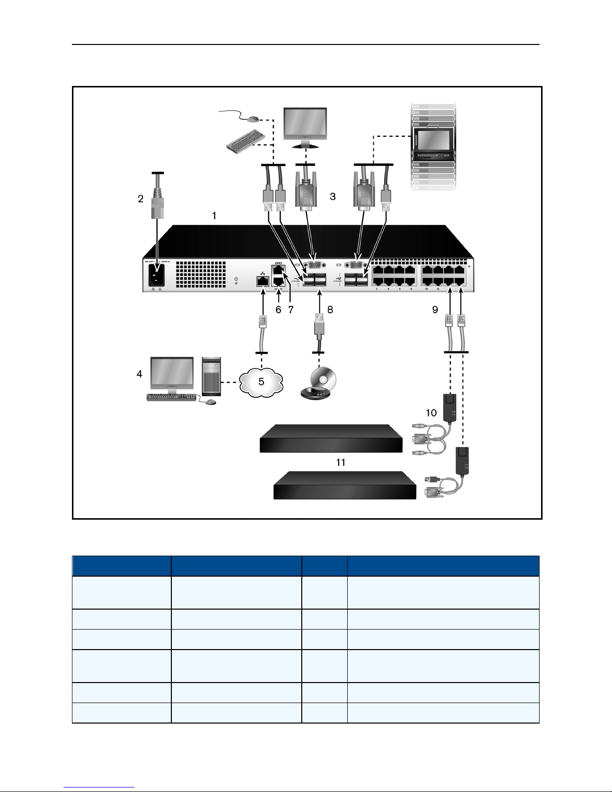
Connecting the AutoView Switch Hardware
The following figure illustrates an example configuration for the AutoView switch.
Page 14
8.....Avocent® AutoView™ 2108/2216/3108/3216 Switch Installer/User Guide
Basic Configuration
Basic Configuration Descriptions
Number Description Number Description
1
AutoView switch(16-Port Model
Shown)
2 Power Cord 8 ExternalVirtualMedia- USB Connections
3 Analog Users (2) 9 Target Device Ports
4
Digital User (requiresthe RAKkey)
5 LAN/Network 11 Servers/Target Devices
6 SETUP Console Setup Port
7 ACI Connection
10 IQ modules
Page 15

Installation.....9
NOTE: The switch supports connecting to another appliance via an ACI connection. This connection
requires that the secondary appliance in the tier have an ACI connector on the user side.
CAUTION: To reduce the risk of electric shock or damage to your equipment, do not disable the jumper
cord grounding plug. The grounding plug is an important safety feature. Plug the jumper cord into a
grounded (earthed) outlet that is easily accessible at all times. Disconnect the power from the unit by
unplugging the jumper cord from either the power source or the unit.
NOTE: If the building has 3-phase AC power, ensure that the computer and monitor are on the same phase
to avoid potential phase-related video and/or keyboard problems.
NOTE: The maximum supported cable length from switch to server is 30 meters.
• Do not disable the power grounding plug. The grounding plug is an important safety feature.
• Connect the jumper cord into a grounded (earthed) outlet that is easily accessible at all times.
• Disconnect the power from the product by unplugging the jumper cord from either the power source
or the product.
• This product has no user-serviceable parts inside the product enclosure. Do not open or remove
product cover.
To connect and turn on your switch:
1. Connect your VGA monitor and USB keyboard and mouse cables to the appropriately labeled ports.
2. Connect one end of a UTP cable (4-pair, up to 98 ft/30 m) to an available numbered port. Connect the
other end to an RJ-45 connector of a IQ module.
3. Connect a IQ module to the appropriate port on the back of a device. Repeat steps 2 and 3 for all devices
you want to connect.
NOTE: When connecting to a Sun Microsystems server, you must use a multi-sync monitor in the local
port to accommodate Sun computers that support both VGA and sync-on-green or composite sync.
4. Connect a user-supplied UTP cable from the Ethernet network to the LAN port on the back of the switch.
Network users will access the switch through this port.
5. Turn on each device, then locate the jumper cord that came with the switch. Connect one end to the
power socket on the rear of the switch. Connect the other end into an appropriate power source.
6. (Optional) Connect the virtual media or smart card readers to any of the USB ports on the switch.
NOTE: For all virtual media sessions, you must use a USB2 or VMC IQ module.
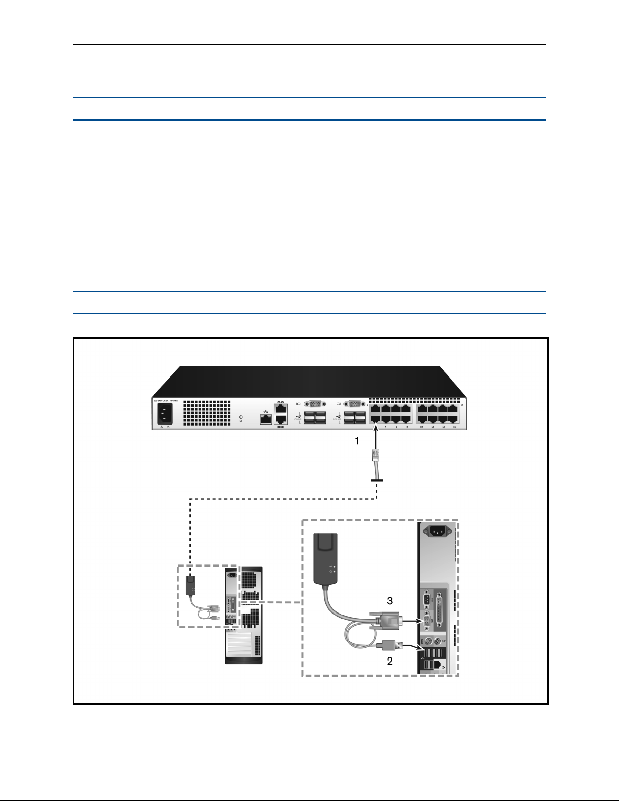
Tiering Your Switch Using an IQ Module
The following figure illustrates a typical IQ module connection between the switch and a device.
Page 16
10.....Avocent® AutoView™ 2108/2216/3108/3216 Switch Installer/User Guide
To connect a IQ module to each device:
NOTE: When tiering devices, the switch closest to the actual user is the primary switch.
1. Locate the IQ modules for your switch.
2. If you are using a PS/2 IQ module connection, attach the color-coded ends of the IQ module cable to the
appropriate keyboard, monitor, and mouse ports on the first device you will be connecting to this switch.
If you are using a USB connection, attach the plug from the IQ module to the USB port on the first device
you will be connecting to this switch.
3. To the RJ-45 connector on the IQ module, attach one end of the CAT 5 cabling that will run from your IQ
module to the switch.
4. Connect the other end of the CAT 5 cable to the desired ARI port on the back of your switch.
5. Repeat steps 2-4 for all devices you wish to attach.
NOTE: Turn off the switch before servicing. Always disconnect the jumper cord from the power source.
IQ Module Connection
Page 17

Installation.....11
Descriptions for IQ Module Configuration
Number Description
1 CAT 5
2 USBConnection
3 VGA Connection
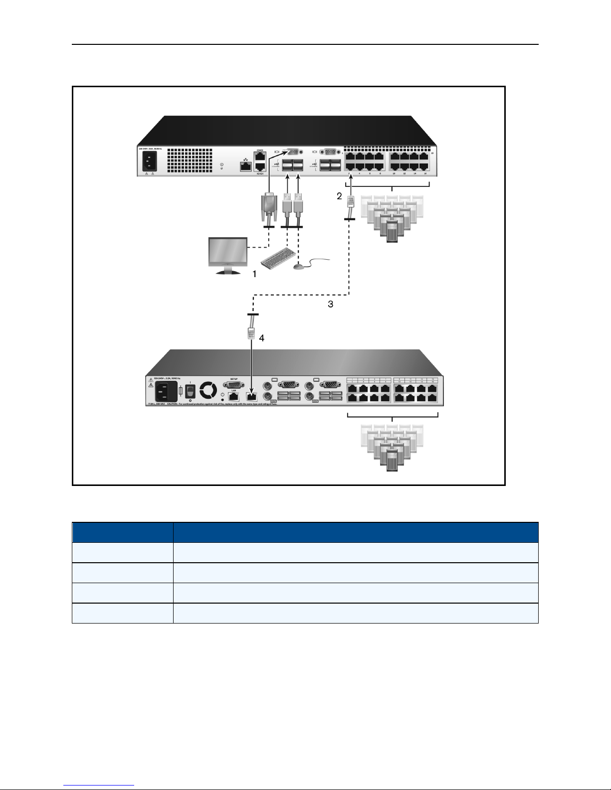
Adding a tiered switch
You can tier up to two levels of switches, enabling users to connect to up to 256 devices. In a tiered system,
each device port on the main switch will connect to the ACI port on each tiered switch. Each tiered switch can
then be connected to a device with an IQ module.
To tier multiple switches:
1. Attach one end of a UTP cable (up to 30 meters in length) to a device port on the switch.
2. Connect the other end of the UTP cable to the ACI port on the back of your tiered switch.
3. Connect the devices to your tiered switch.
4. Repeat these steps for all the tiered switches you wish to attach to your system.
NOTE: The system automatically “merges” the two switches. All switches connected to the tiered switch
are displayed on the main switch list in the local UI.
NOTE: The switch supports one tiered switch per device port of the main switch. You cannot attach a
switch to the tiered switch.
Page 18
12.....Avocent® AutoView™ 2108/2216/3108/3216 Switch Installer/User Guide
Tiering the Switch With a UTP Analog Switch
Descriptions for Tiering the Switch
Number Description
1 LocalUser
2 ARI Connection
3 UTP Connection
4 ACI Connection (chainicon)
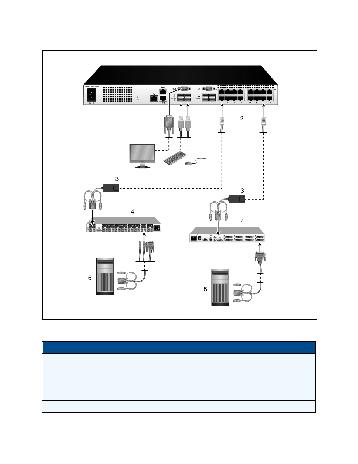
Adding a tiered legacy switch
The following figure illustrates a tiered legacy switch configuration.
To add a legacy switch (optional):
1. Mount the switch into your rack. Locate a UTP cable (up to 30 meters) to connect your switch to the
legacy switch.
2. Attach one end of the UTP cabling to the ARI port on your switch.
Page 19

Installation.....13
3. Connect the other end of the UTP cable to a PS/2 IQ module.
4. Connect the IQ module to the legacy switch according to the switch manufacturer's recommendations.
5. Repeat steps 1-4 for all the legacy switches you wish to attach to your switch.
NOTE: The primary switch supports only one switch per ARI port or USB port. You cannot tier a switch to
a tiered switch.
Page 20
14.....Avocent® AutoView™ 2108/2216/3108/3216 Switch Installer/User Guide
Tiering Legacy Switches
Descriptions for Tiering Legacy Switches
Number Description
1 LocalUser
2 ARI Connection
3 IQ module
4 PS2Connection
5 Target Device Connection
Page 21

Installation.....15
Configuring Your Switch
Once all physical connections have been made, you will need to configure the switch for use in the overall
switch system. This can be accomplished using serial interface, OBWI, OSCAR, or the DSView
management software. When configuring the switch using OSCAR, see Network Settings on page 35. When
using DSView management software on the 2108/2216 switch models, the RAK-key is required. See the
applicable Avocent Installer/User Guide for detailed instructions.
Setting Up the Built-in Web Server
Before using the OBWI to access the switch, the IP address must be specified using the setup port on the
back panel of the switch, or through the local user interface (OSCAR). To use the switch UI, see Local
OSCAR™ User Interface on page 17.
Connecting to the OBWI Through a Firewall
For switch installations that use the OBWI for access, the following ports must be opened in a firewall if
outside access is desired.
OBWI Ports With a Firewall
Port Number Function
TCP 80 Usedfor the initial downloadingof the Video Viewer. The appliance administrator canchangethisvalue.
TCP 443
TCP 2068
TCP/UDP 3211 Discovery(requiresthe RAK-key for the 2108/2216 switchmodels).
The following figure and table provide a typical configuration where the user’s computer is located outside of
the firewall and the switch resides inside the firewall.
Typical Firewall Configuration
Usedby theweb browser interface for managing the switch and launchingKVM sessions.The appliance
Admin can change this value.
Transmissionof KVM session data (mouseand keyboard) or transmission ofvideoon switches (requires the
RAK-keyfor the2108/2216 switch models).
Page 22

16.....Avocent® AutoView™ 2108/2216/3108/3216 Switch Installer/User Guide
Descriptions for Firewall Configuration
Item Description
1 Avocent® AutoView™ 2108/2216/3108/3216Switch
2 Firewall
3 Computer
4 Firewallforwards HTTP requestsand KVMtraffic to the switch
5 Connection toan IPaddressoutsidethe firewall
To configure the firewall:
To access the switch from outside a firewall, configure your firewall to forward ports 80 and 443 from its
external interface to the KVM switch through the firewall’s internal interface. Consult your firewall manual for
specific port forwarding instructions.
NOTE: Ports 80 and 443 can be reconfigured by an administrator. You must reboot for a port change to
take effect.
For information on launching the OBWI, see OBWI Operation on page 29.
Verifying Power Status
The switch has one power supply. The LED illuminates when the switch is turned on and operating normally.
Adjusting Mouse Settings on Target Devices
Before a computer connected to the switch can be used for remote user control, you must either enable
Avocent Module Sync (see Mouse Settings for additional information) or set the target mouse speed and turn
off acceleration. For machines running Microsoft®Windows®(Windows NT®, 2000, XP, or Server 2003), use
the default USB mouse driver.
To ensure that the local mouse movement and remote cursor display remain in sync, mouse acceleration
must be set to none for all user accounts accessing a remote system through a KVM switch. Mouse
acceleration must also be set to none on every remote system. Special cursors should not be used and cursor
visibility options, such as pointer trails, Ctrl key cursor location animations, cursor shadowing, and cursor
hiding, should also be turned off.
NOTE: If you are not able to disable mouse acceleration from within a Windows operating system, or if you
do not wish to adjust the settings of all your target devices, you may use the Tools - Single Cursor Mode
command available in the Video Viewer window. This command places the Video Viewer window into an
“invisible mouse” mode, which allows you to manually toggle control between the mouse pointer on the
device system being viewed and the mouse pointer on the client computer.
Page 23

Local OSCAR™ User Interface
The AutoView switch features user-side keyboard and mouse ports that allow you to connect a USB keyboard
and mouse for direct analog access. The switch uses the OSCAR interface to configure your system and
devices. You can use the OSCAR interface to access devices that are attached to the AutoView switch.
Main Dialog Box Functions
To access the OSCAR interface Main dialog box:
Press Print Screen to launch the OSCAR interface. The Main dialog box will appear.
NOTE: If the OSCAR password has been enabled, you will be prompted to enter a password before you
can launch the OSCAR interface.
Viewing and selecting ports and devices
Use the OSCAR Main dialog box to view, configure, and control devices in the switch system. View your
devices by name, port, or by the unique EID number embedded in each IQ module.
In the following figure, the Port column indicates the ARI port to which a device is connected. If you tier a
switch from the main switch, creating another tier, the ARI port on the switch is listed first, and is followed by
the switch port to which the device is connected.
OSCAR Interface Main Dialog Box
Page 24

18.....Avocent® AutoView™ 2108/2216/3108/3216 Switch Installer/User Guide
NOTE: You can press the Control , Alt or Shift keys twice within one second to launch the OSCAR
interface. You can use this key sequence when you see Print Screen throughout this chapter.
Main Dialog Box Functions
Button Function
Name Name ofdevice.
EID UniqueEID ina module.
Port The port to whicha deviceisconnected.
Clear Clear all offline IQ modules.
Disconnect Disconnect theKVMsession.
Setup Accessthe Setupdialogbox and configure theOSCAR interface.
Commands Accessthe Commandsdialog box.
VMedia Control virtualmedia connection.
Viewing switch system status
The status of devices in your system is indicated in the right column of the Main dialog box. The following
table describes the status symbols.
OSCAR Interface Status Symbols
Symbol Description
(Green circle) deviceconnected,turned on,and theIQ moduleis online.
Connecteddevice is turnedoff or isnot operatingproperly, and theIQ moduleisoffline.
Connectedswitch is online.
Connectedswitch is offlineor not operating properly.
(Yellow circle) The designatedIQ moduleisbeing upgraded. When this symboldisplays, donot cycle power to the
switch or connecteddevicesand donot disconnect the IQ module. Doing so may render themodule permanently
inoperable andrequire theIQ module to be returned tothe factory for repair.
(Green letter) IQ moduleisbeing accessed by theindicated user channel.
Page 25

Local OSCAR™ User Interface.....19
Symbol Description
(Blackletter) IQ moduleisblocked bythe indicateduser channel.
(Red letter)Smart card support isavailable.
Selecting devices
Use the Main dialog box to select a device. When you select a device, the switch reconfigures the local
keyboard and mouse to the settings for that device.
To select a device:
Double-click the device name, EID, or port number.
or-
If the display order of your list is by port (the Port button is depressed), type the port number and press Enter .
-or-
If the display order of your list is by name or EID (the Name or EID button is depressed), type the first few
letters of the name of the device or the EID number to establish it as unique and press Enter.
To select the previous device:
Press Print Screen and then Backspace. This key combination toggles between the previous and current
connections.
To disconnect from a device:
Press Print Screen and then Alt+0 (zero). This leaves the user in a free state, with no device selected. The
status flag on your desktop displays the word Free.
Soft switching
Soft switching is the ability to switch devices using a hotkey sequence. You can soft switch to a device by
pressing Print Screen, and then depending on the method you’ve selected, typing the first few characters of
its name or number. If you have set a Screen Delay Time for the OSCAR interface and you press the key
sequences before that time has elapsed, the OSCAR interface will not be displayed.
To soft switch to a device:
Press Print Screen, type the port number and the first few letters of the name of the device, to establish it as
unique and press Enter.
To switch back to the previous device, press Print Screen and then Backspace.
Navigating the OSCAR interface
The following table describes how to navigate the OSCAR interface using the keyboard and mouse.
Page 26

20.....Avocent® AutoView™ 2108/2216/3108/3216 Switch Installer/User Guide
OSCAR Interface Navigation Basics
Keystroke Function
Print Screen,
Ctrl+Ctrl, Shift+Shift
and/or Alt+Alt
F1
Escape
Alt
Alt+X
Alt+O
Enter
Single-click, Enter
Print Screen,
Backspace
Print Screen, Pause
OSCAR interface activation sequence. Bydefault, Print Screen and Ctrl+Ctrlare set asthe OSCAR
interfaceactivationoptions. Shift+Shift and Alt+Alt mustbe set withinthe OSCAR interfacebefore use.
Opens the Help screen forthe current dialog box.
Closes the current dialogbox withoutsaving changesand returnsto thepreviousone. Ifthe Main dialog
boxisdisplayed,pressingEscape closesthe OSCAR interface and displays a statusflagif statusflagsare
enabled. SeeCommandsDialogBox Functions on page 25 for more information. In a message box,
pressing Escape closes the pop-up boxand returns tothe current dialog box.
Opens dialog boxes, selects or checks options,and executesactions when usedwith underlinedor other
designated letters.
Closes current dialogbox and returns topreviousone.
Selectsthe OK button, thenreturns to the previous dialog box.
Completesa switch operation in the Main dialogbox and exits the OSCAR interface.
In atext box, single-clicking anentry andpressing Enter selectsthe text for editingand enablesthe left
and right arrow keysto movethe cursor. Press Enter again toquit the Editmode.
Togglesbackto previousselection.
Immediatelyturns onScreen Saver modeand prevents accessto that specific console, if it ispassword
protected.
Up/Down Arrows
Right/Left Arrows
Page Up/Page Down
Home/End
Backspace
Movesthe cursor from lineto line in lists.
Movesthe cursor between columns.When editing a textbox, these keysmovethe cursor within the
column.
Pagesup anddown throughName andPort listsand Help pages.
Movesthe cursor to the top or bottomof alist.
Erasescharactersin a textbox.
Connecting local virtual media
You can connect virtual media directly to the switch using a USB port on the switch.
NOTE: All USB ports are assigned to a single virtual media session and cannot be independently mapped.
To start a local virtual media session, complete the following steps:
1. Press Print Screen to start the OSCAR interface and open the Main window.
2. Connect the user to the device with which you want to establish a virtual media session.
3. Use the arrow keys to highlight the device name, and then press Enter.
4. Press Print Screen to start the OSCAR interface again. The Virtual Media window is displayed.
5. Select one or more of the following checkboxes:
Page 27

• Locked - Select this checkbox to specify that when the user is disconnected from a device, the
virtual media is also disconnected.
• Reserve - Select this checkbox to specify that the virtual media connection can be accessed only
by your user name and that no other user can connect to that device. If both Locked and Reserved
are selected, the session will be reserved.
• CD ROM - Select this checkbox to establish a virtual media CD connection to a device. Clear this
checkbox to end the connection.
• Mass Storage - Select this checkbox to establish a virtual media mass-storage connection to a
device. Clear this checkbox to end the connection.
• Write Access - Select this checkbox to enable the connected device to write data to the virtual
media during a virtual media session. Read access is always enabled during virtual media
sessions.
6. Click OK.
Setup Dialog Box Functions
Local OSCAR™ User Interface.....21
You can configure your switch system from the Setup dialog box within the OSCAR interface. Select the
Names button when initially setting up your switch to identify devices by unique names. Select the other
setup features to manage routine tasks for your devices from the OSCAR interface menu. The following table
lists the functions accessed using each of the buttons in the Setup dialog box.
To access the OSCAR interface Setup dialog box, click Setup on the Main dialog box.
Setup Dialog Box Features
Feature Purpose
Change the Maindialogbox listsorting option bytogglingnumericallybetween port number, EID number, or
Menu
Security Set passwordsto protector restrictaccess or enablethe screen saver.
Devices Identifythe appropriatenumber of portson an attached tiered switch.
Names Identifydevicesby unique names.
Keyboard Set the keyboard country code valuefor the USBdevices.
Broadcast Set up to simultaneouslycontrolmultiple devicesthrough keyboard and mouse actions.
Switch Change how local port connectionsare managedby theswitch. ControlLocalto LocalShare Mode.
alphabeticallyby name. Changethe Screen Delay Time before the OSCARinterface displaysafter pressing Print
Screen.You can alsochangehow the OSCAR interface activation sequenceis invoked.
Network Choose your networkspeed, transmission mode, andconfiguration.
Scan Set up a custom Scan pattern for multiple devices.
VMedia Set thebehaviour of the switch during avirtualmediasession.
Page 28

22.....Avocent® AutoView™ 2108/2216/3108/3216 Switch Installer/User Guide
Changing the display behavior
Use the Menu dialog box to change the order of displayed devices, change how the OSCAR interface is
invoked, or set a Screen Delay Time for the OSCAR interface. This setting alters how devices are displayed
in several dialog boxes, including the Main, Devices, and Scan List boxes.
To access the OSCAR interface Menu dialog box, activate the OSCAR interface and click Setup - Menu in
the Main dialog box.
To choose the display order of devices:
1. Select Name to display devices alphabetically by name.
-or-
Select EID to display devices numerically by EID number.
-or-
Select Port to display devices numerically by port number.
2. Click OK.
Depending on the display method selected, the corresponding button will be depressed in the Main dialog box.
To change how the OSCAR interface is invoked:
1. Select the checkbox next to one of the listed methods.
2. Click OK.
To set a Screen Delay Time for the OSCAR interface:
1. Type in the number of seconds (0-9) to delay the OSCAR interface display after you press Print Screen.
Enter 0 to launch the OSCAR interface with no delay.
2. Click OK.
Setting a Screen Delay Time enables you to complete a soft switch without the OSCAR interface. To perform
a soft switch, see Soft switching on page 19.
Controlling the status flag
The status flag displays on your desktop and shows the name or EID number of the selected device or the
status of the selected port. Use the Flag dialog box to configure the flag to display by device name or EID
number, or to change the flag color, opacity, display time, and location on the desktop.
To access the OSCAR interface Flag dialog box:
Activate the OSCAR interface and click Setup - Flag to open the Flag dialog box.
To determine how the status flag is displayed:
1. Select Name or EID to determine what information will be displayed. The following interface Status
Flags are available.
• Flag Description
• Flag type by name
• Flag type by EID number
• Flag indicating that the user has been disconnected from all systems
Page 29

Local OSCAR™ User Interface.....23
2. Select Displayed to activate the flag display. After a switch, the flag will remain on the screen until the
user switches to another device. Selecting Timed will cause the flag to display for five seconds when a
switch is made and then disappear.
3. Select a flag color under Display Color. The following flag colors are available:
• Flag 1 - Gray flag with black text
• Flag 2 - White flag with red text
• Flag 3 - White flag with blue text
• Flag 4 - White flag with violet text
4. In Display Mode, select Opaque for a solid color flag or Transparent to see the desktop through the flag.
5. To position the status flag on the desktop:
a. Click Set Position to gain access to the position flag screen.
b. Left-click on the title bar and drag it to the desired location.
c. Right-click to return to the Flag dialog box.
NOTE: Changes made to the flag position are not saved until you click OK in the Flag dialog box.
6. Click OK to save settings.
-or-
Click X to exit without saving changes.
Setting the keyboard country code
NOTE: Using a keyboard code that supports a language different from that of your switch firmware will
cause incorrect keyboard mapping.
By default, the switch sends the US keyboard country code to USB modules attached to devices, and the
code is applied to the devices when they are turned on or rebooted. Codes are then stored in the IQ module.
Issues may arise when you use the US keyboard country code with a keyboard of another country.
For example, the Z key on a US keyboard is in the same location as the Y key on a German keyboard. The
Keyboard dialog box enables you to send a different keyboard country code than the default US setting. The
specified country code is sent to all devices attached to the switch when they are turned on or rebooted, and
the new code is stored in the IQ module.
NOTE: If an IQ module is moved to a different device, the keyboard country code will need to be reset.
Assigning device types
To access the OSCAR interface Devices dialog box:
Activate the OSCAR interface and click Setup - Devices to open the Devices dialog box.
NOTE: The Modify button is available only if a configurable switch is selected.
Page 30

24.....Avocent® AutoView™ 2108/2216/3108/3216 Switch Installer/User Guide
When the switch discovers a tiered switch, the numbering format changes from switch port to [switch port]-
[switch port] to accommodate each device under that switch.
For example, if a switch is connected to console switch port 6, each device connected to it would be
numbered sequentially. The device using console switch port 6, switch port 1, would be 06-01, the device
using console switch port 6, switch port 2, would be 06-02, and so on.
To assign a device type:
1. In the Devices dialog box, select the desired port number.
2. Click Modify to open the Device Modify dialog box.
3. Choose the number of ports supported by your switch and click OK.
4. Repeat steps 1-3 for each port requiring a device type to be assigned.
Assigning device names
Use the Names dialog box to identify devices by name rather than by port number. The Names list is always
sorted by port order. You can toggle between displaying the name or the EID number of each IQ module, so
even if you move the IQ module/device to another port, the name and configuration will be recognized by the
switch.
NOTE: When it is initially connected, a device will not appear in the Names list until it is turned on. Once an
initial connection has been made, it will appear in the Names list even when turned off.
To access the OSCAR interface Names dialog box, activate the OSCAR interface and click Setup - Names.
NOTE: If new IQ modules are discovered by the switch, the on-screen list will be automatically updated.
The mouse cursor will change into an hourglass during the update. No mouse or keyboard input will be
accepted until the list update is complete.
To assign names to devices:
1. In the Names dialog box, select a device name or port number and click Modify to open the Name
Modify dialog box.
2. Type a name in the New Name box. Names of devices may contain all printable characters.
3. Click OK to assign the new name.
4. Repeat steps 1-3 for each device in the system.
5. Click OK in the Names dialog box to save your changes.
-or-
Click X or press Escape to exit the dialog box without saving changes.
Configuring network settings
Use the Network dialog box to set the Network Speed, Transmission Mode, and Network Configuration
feature.
To change network settings:
1. If the OSCAR interface is not open, press Print Screen to open the Main dialog box.
Page 31

Local OSCAR™ User Interface.....25
2. Click Setup - Network to open the Network dialog box.
3. Make desired changes and click OK to confirm or click X to exit without saving.
NOTE: Changing the network settings will cause the switch to reboot.
4. Click OK in the Devices dialog box to save settings.
NOTE: Changes made in the Device Modify dialog box are not saved to the switch until you click OK in the
Device Modify dialog box.
NOTE: Changes made in the Name Modify dialog box are not saved to the switch until you click OK in the
Names dialog box.
NOTE: If an IQ module has not been assigned a name, the EID is used as the default name.
Commands Dialog Box Functions
From the OSCAR interface Commands dialog box, you can manage your switch system and user
connections, enable the Scan mode, and update your firmware.
Commands to Manage Routine Tasks for Your Devices
Features Purpose
Beginscanningyour devices. Set upa devicelist for
ScanEnable
User Status View anddisconnect users.
IQ Module Status
DisplayVersions
DisplayConfig Viewcurrent configurationparameters.
Device Reset
To access the OSCAR interface Commands dialog box:
scanningin theSetup dialog box. You must have at least
two devices selected in theSetup -Scan List menu to
enabledevice scanning.
Displaythe currentlyavailable firmware for eachtypeof
IQ module.
Viewversioninformationfor the switchas well as view and
upgrade firmware for individualIQ modules.
Re-establishoperation ofkeyboard and mouse onthe
local port.
Activate the OSCAR interface and click Commands to open the dialog box.
Selecting devices for scan mode
The Scan dialog box allows the local user to define a custom list of devices to include while in Scan mode and
the number of seconds to display each device. The creation of the Scan list does not start Scan mode. You
must enable Scan mode using the Scan Enable checkbox on the Commands dialog box. The Scan list is
displayed in the manner set from the Menu dialog box. It can be changed in the Scan dialog box to sort either
Page 32

26.....Avocent® AutoView™ 2108/2216/3108/3216 Switch Installer/User Guide
by name, EID, or port by choosing one of the buttons. If a device on the list is unavailable, it is skipped. Watch
mode views a device unless a conflicting network user blocks the path to that device. If a conflict is detected
in Watch mode (or the device is unavailable), the device to be viewed is skipped.
To add devices to the Scan list:
1. Activate the OSCAR interface and click Setup - Scan to open the Scan dialog box.
2. The dialog box contains a listing of all devices attached to your switch. Click the checkbox to the right of
the device, double-click on the desired entry, or highlight the device, and click the Add/Remove button to
toggle the Scan checkbox setting. You can select up to 100 devices for inclusion in the Scan list.
NOTE: Click the Clear button to remove all devices from the Scan list.
3. In the Time field, type the number of seconds (from 3 - 255) to display each device while scanning. The
default is 15 seconds per device.
4. Click OK.
NOTE: The order in which the devices appear in the Scan dialog box is based on the order in which they
were selected. Scanning a single device multiple times during a loop is not supported. Scan time must be
the same for all devices.
Enabling or disabling scan mode
To start the Scan mode:
1. Activate the OSCAR interface and click Commands. The Commands dialog box is displayed.
2. Select Scan Enable in the Commands dialog box. Scanning will begin.
3. Click X to close the Commands dialog box.
To cancel Scan mode:
Select a device if the OSCAR interface is open.
-or-
Move the mouse or press any key on the keyboard if the OSCAR interface is not open. Scanning will stop at
the currently selected device.
-or-
From the Commands dialog box, clear the Scan Enable checkbox.
Viewing and disconnecting user connections
You can view and disconnect users through the User Status dialog box. The username (U) and server (S) will
always be displayed when connected to a device (local or remote). You can display either the device name or
EID number to which a user is connected. If there is no user currently connected to a channel, the username
and device fields will be blank.
To view current user connections, activate the OSCAR interface and click Commands > User Status to open
the User Status dialog box.
Page 33

Local OSCAR™ User Interface.....27
To disconnect a user:
1. On the User Status dialog box, click the letter corresponding to the user to disconnect. The Disconnect
dialog box will appear.
2. Click Disconnect to disconnect the user and return to the User Status dialog box.
-or-
Click X or press Escape to exit the dialog box without disconnecting a user.
Displaying version information and upgrading firmware
For troubleshooting and support, the OSCAR interface enables you to display the version number of the
switch firmware and any auxiliary devices connected to the switch, as well as upgrade your firmware for
optimum performance.
To display version information and upgrade firmware:
1. Activate the OSCAR interface and click Commands - Display Versions. The top half of the box lists the
subsystem version in the switch. The lower half displays the current IP address, Mask, MAC, and EID.
2. If you want to upgrade the firmware, click Upgrade and then click OK to open the download box. You will
be prompted for an FTP or TFTP device IP address and the related information.
3. Click Download. After the firmware is downloaded, the Upgrade dialog box will appear.
4. Click the Upgrade button.
NOTE: The switch will reboot when the upgrade is complete.
To upgrade individual IQ modules:
1. Click the IQ button to view individual IQ module version information.
2. Select the IQ button to view and click the Version button.
3. Click the Load Firmware button.
4. Click OK to initiate the upgrade and return to the Status dialog box.
NOTE: During an upgrade, the IQ module status indicator in the Main dialog box is yellow. The IQ modules
are unavailable when an upgrade is in progress. When an upgrade is initiated, any current connection to the
device using the IQ module is terminated.
To simultaneously upgrade multiple IQ modules:
1. Activate the OSCAR interface, click Commands - IQ Status and click one or more types of IQ modules
to upgrade.
2. Click Upgrade.
NOTE: When the Enable IQ Auto update option is enabled in the IQ Status dialog box, IQ module firmware
is automatically upgraded when the switch firmware is upgraded or when a new IQ module is discovered by
the switch after a firmware upgrade. IQmodules that have already been discovered but which are not
attached to the switch during the firmware upgrade must be upgraded manually.
Page 34

28.....Avocent® AutoView™ 2108/2216/3108/3216 Switch Installer/User Guide
3. The IQ Upgrade dialog box is displayed. Click OK to initiate the upgrade and return to the IQ Status
dialog box.
To return an IQ module to factory default status:
1. Click IQ in the Version dialog box.
2. Select an IQ module, then click Decommission.
3. Click OK to restore factory defaults. You will see the IQ module go offline briefly and return.
- or-
Click X or press Escape to cancel the operation.
4. Click X to close the IQ Select dialog box.
Page 35

OBWI Operation
The OBWI for the AutoView switch is a remote, web browser-based user interface. For details on setting up
your system, see Connecting the AutoView Switch Hardware on page 7. The following table lists the
operating systems and browsers that are supported by the OBWI. Make sure that you are using the latest
version of your Web browser.
Operating Systems Supported by the OBWI
Browser
Operating System
Microsoft WindowsServer
2003 Standard, Enterprise
or WebEdition
Microsoft WindowsXP
Home Edition or
Professional
Microsoft Windows7 or 8 Yes Yes Yes
Microsoft WindowsServer
2012
Microsoft®Internet
Explorer®Version 9.0
®
Yes Yes Yes
Yes Yes Yes
®
Yes Yes Yes
Firefox Version 10 and Later
Google Chrome Version19 and
Later
Microsoft Windows2008 Yes Yes Yes
Red HatEnterprise Linux®5
and 6
CanonicalUbuntu 12.04 No Yes No
SunSolaris®10 and 11 No Yes No
Novell SUSE Linux
Enterprise10 and11
AppleMacOS XTiber 10.4+ No Yes No
To log in to the switch OBWI:
1. Launch a web browser.
2. In the address field of the browser, enter the IP address or host name assigned to the switch you wish to
access. Use https://xxx.xx.xx.xx or https://hostname as the format.
NOTE: If using IPv6 mode, you must include square brackets around the IP address. Use https://
[<ipaddress-] as the format.
3. When the browser makes contact with the switch, enter your username and password, then click Login.
The switch OBWI will appear.
No Yes No
No Yes No
NOTE: The default username is Admin with no password.
Page 36

30.....Avocent® AutoView™ 2108/2216/3108/3216 Switch Installer/User Guide
To log in to the switch OBWI from outside a firewall, repeat the above procedure, entering the external IP
address of the firewall instead.
NOTE: The switch will attempt to detect if Java is already installed on your PC. If it is not, in order to use
the OBWI, you will need to install it. You may also need to associate the JNLP file with Java WebStart.
NOTE: Using the OBWI requires using Java Runtime Environment (JRE) version 1.6.0_11 or higher.
NOTE: Once you have logged in to the OBWI, you will not have to log in again when launching new
sessions unless you have logged out or your session has exceeded the inactivity timeout specified by the
administrator.
Using the OBWI
After you have been authenticated, the user interface appears. You may view, access, and manage your
switch, as well as specify system settings and change profile settings. The following figure shows the user
interface window areas. Screen descriptions are provided in the following table.
OBWI Window
Descriptions for the OBWI
Number Description
1
2
3 Content area: Use thecontentarea to display or make changesto theswitchOBWI system.
Top option bar:Use thetop option barto contact TechnicalSupport, view the software general information, log out
of anOBWI session, or accessthe Helptool
Sidenavigationbar: Use the side navigation bar to select theinformationto bedisplayed.You can use the side
navigationbar to displaywindows in which you can specifysettingsor perform operations.
Page 37

OBWI Operation.....31
Viewing System Information
You can view switch and target device information from the following screens in the user interface.
System Information
Category Select This: To View This:
List ofconnected devices, as wellas thename, type, status,and actionof
Target Devices Unit View - Target Devices
eachdevice. Clickon a targetdevice toviewthe followinginformation:name,
type,EID, available session option, andthe connection path.
AutoView switch UnitView - Appliance- Tools
Unit View - Appliance - Files Configuration andUser Database forthe switch.
Unit View - Appliance Properties- Identity
Unit View - Appliance Properties- Location
Unit View - Appliance SettingsVersions
Unit View - Appliance SettingsNetwork
Unit View - Appliance SettingsSNMP
Unit View - Appliance SettingsAuditing
Unit View - Appliance SettingsPorts
Unit View - Appliance Settings
Sessions
Name, type, and the switchtools(Maintenance-Overview/Reboot/Resetand
Upgrade, Certificates, andTrap MIB).
Part number, serial number, andstatusof theRAK-key(default settingis
disabled).
Site,department, and location ofeach unit.
Current application, boot, build,hardware, UART, and video ASIC versions.
Network address, LAN speed, andweb server ports.
System description, SNMPsetting, contact,read/write and trap settings, and
designationsfor allowedmanagers.
Events listand status and SNMPtrap destinations.
Status, EID,name, port,applicationand interface type for each IQ adaptor;
name, port, type, channels, andstatusfor eachtiered switch.
General session timeout andsharingdetails; KVM encryptionlevels and
keyboard language; virtual media settings, drive mappings,encryption level,
and IQ adaptoraccess.
Unit View - Appliance - User
Accounts
Unit View - Appliance Connections
ActiveSessions Server, owner, remotehost, duration,and type ofeachactivesession.
NOTE: IQ adaptor and IQ module are used interchangeably. In the OSCAR interface IQ module is the term
used. In the OBWI, IQ adaptor is the term used.
Security and user lock-outfor the localaccount; authenticationserver
assignmentsfor DSView management software, andoverride admin
usernameand password in caseof a failed operation.
Connection path nameand type.
Page 38

32.....Avocent® AutoView™ 2108/2216/3108/3216 Switch Installer/User Guide
Generating a Certificate
A web certificate allows you to access the OBWI without having to acknowledge the switch as a trusted web
device each time you access it. Using the Install Web Certificate window, you can generate a new self-signed
openssl or upload a certificate. Uploaded certificates must be in OpenSSL PEM format with an unencrypted
private key.
To install a web certificate:
1. From the side navigation bar, select Unit View - Appliance - Overview.
2. Click Manage Appliance Web Certificate.
3. Click Update.
4. Select the Generate a new Self-Signed Certificate radio button and enter the following fields:
• Common Name: your name. (Since this is your root certificate, use an appropriate name such as,
"Company_Name Certificate Authority.")
• Organization: organization unit name (marketing, for example).
• City or Locality: the city where your organization is located.
• State or Province: the unabbreviated state or province where your organization is located.
• Country: the two-letter ISO abbreviation for your country.
• Email Address: the email address for the Certificate Authority (CA) to contact.
5. Click Generate to create the certificate.
To upload a new certificate:
1. Click the Upload a New Certificate radio button.
2. Select the method (Filesystem, TFTP, FTP, or HTTP).
3. Click Browse to search for the certificate or enter the certificate filename.
4. Select Install. Close the web browser, then launch the OBWI again for the same IP address.
NOTE: If importing a company certificate file, it may take up to 30 seconds for the OBWI to launch.
5. When prompted, click to view the certificate and follow the instructions to import the certificate into the
Root Certificate Authority folder. After the certificate is stored, the user should not see the certificate
warning.
Tools - Rebooting and Upgrading
From the Unit View - Appliance - Overview page, you can view the switch name and type. You can also
perform the following tasks.
Rebooting the Switch
To reboot the switch:
1. From the side navigation bar, click Unit View - Appliance - Overview to open the Unit Maintenance
screen.
2. Click the Reboot button.
Page 39

OBWI Operation.....33
3. A dialog box appears, warning you that all active sessions will be disconnected. Click the OK button.
NOTE: If you are using the local UI, the screen will be blank while the switch reboots. If you are using the
remote OBWI, a message will appear to let you know that the interface is waiting on the switch to complete
the reboot.
Upgrading switch firmware
You can update your switch with the latest firmware available.
After the memory is reprogrammed with the upgrade, the switch performs a soft reset, which terminates all IQ
adaptor sessions. A target device experiencing an IQ adaptor firmware update may not display, or may
display as disconnected. The target device will appear normally when the update is completed.
Attention: Disconnecting an IQ adaptor during a firmware update or cycling power to the target device will
render the module inoperable and require the IQ adaptor to be returned to the factory for repair.
To upgrade the switch firmware:
1. From the side navigation bar, click Unit View - Appliance - Overview to open the Unit Maintenance
screen.
2. Click Upgrade Firmware.
3. Select one of the following methods to load the firmware file: Filesystem, TFTP, FTP, or HTTP.
NOTE: The Filesystem option is only available on the remote OBWI.
4. If you selected Filesystem, select Browse to specify the location of the firmware upgrade file.
-or-
If you selected TFTP, enter the Server IP Address and Firmware File you wish to load.
-or-
If you selected FTP or HTTP, enter the Server IP Address and Firmware File you wish to load, as well
as the User Name and User Password.
5. Click the Upgrade button.
Saving and restoring configurations and user databases
You may save the switch configuration to a file. The configuration file will contain information about the
managed switch. You may also save the local user database on the switch. After saving either file, you may
also restore a previously saved configuration file or local user database file to the switch.
To save a managed switch configuration or user database of a managed switch:
1. From the side navigation bar, click Unit View - Appliance - Overview.
2. Click either the Save Appliance Configuration or Save Appliance User Database, then click the Save
tab.
3. Select the file save method: Filesystem, TFTP, FTP, or HTTP PUT.
4. If you selected TFTP, enter the Server IP Address and Firmware Filename you wish to load.
-or-
Page 40

34.....Avocent® AutoView™ 2108/2216/3108/3216 Switch Installer/User Guide
If you selected FTP or HTTP, enter the Server IP Address, Username, User Password, and Firmware
Filename you wish to load.
5. Click the Download button. The Save As dialog box will open.
6. Navigate to the desired location and enter a name for the file. Click the Save button.
To restore a managed switch configuration or user database of a managed switch:
1. From the side navigation bar, click the Unit View - Appliance - Overview.
2. Click either the Restore Appliance Configuration or Restore Appliance User Database, then click the
Restore tab.
3. Select the file save method: Filesystem, TFTP, FTP, or HTTP.
4. If you selected Filesystem, click the Browse button to specify the location of the firmware upgrade file.
-or-
If you selected TFTP, enter the Server IP Address and Firmware Filename you wish to load.
-or-
If you selected FTP or HTTP, enter the Server IP Address, User Name, User Password, and Firmware
Filename you wish to load.
5. Click the Browse button. Navigate to the desired location and select the file name. Click the Upload
button.
6. After the success screen appears, reboot the managed switch to enable the restored configuration.
Recovering From a Failed Flash Upgrade
NOTE: You may only recover from a failed Flash upgrade when using IPv4 mode. If the green power LED
on the front and back panel of the Remote Console switch blinks continuously, the Remote Console switch
is in recovery mode.
To recover from a failed Flash upgrade:
1. Download the latest Flash firmware.
2. Save the Flash upgrade file to the appropriate directory on the TFTP server.
3. Set up the TFTP server with the server IP address 10.0.0.20.
4. Rename the downloaded file “CMN-1095.fl” and place it into the TFTP root directory of the TFTP server.
5. If the Remote Console switch is not on, turn it on now. The recovery process should start automatically.
Property Identity and Location Settings
The switch can report most device properties directly through the switch web browser. Clicking Identity
displays the Unit Identification Properties screen and provides the Part Number, Serial Number, and status of
the RAK-key. The Unit Location Properties screen displays the Site, Department and Location.
Viewing Version Information
The Version screen displays version information of the Current Application, Boot, Build, Hardware, UART,
and Video ASIC versions. This screen is a read-only screen.
Page 41

OBWI Operation.....35
Network Settings
NOTE: Only administrators can make changes to the Network dialog box settings. Other users will have
view only access.
From the side navigation bar, click Network to display the General, IPv4, and IPv6 tabs.
To configure general network settings:
1. Click the Network tab, then click the General tab to display the switch General Network Settings
screen.
2. Select one of the following options from the LAN Speed drop-down menu: Auto-Detect, 10 Mbps Half
Duplex, 10 Mbps Full Duplex, 100 Mbps Half Duplex, or 100 Mbps Full Duplex.
NOTE: You must reboot if you change the Ethernet mode.
3. Select either Enabled or Disabled in the ICMP Ping Reply drop-down menu.
4. Verify or modify the HTTP or HTTPS ports. The settings will default to HTTP 80 and HTTPS 443.
5. Click Save.
To configure IPv4 network settings:
1. Click the Network tab, then click the Address tab to display the IPv4 Settings screen.
2. Click the IPv4 button.
3. Click to fill or clear the Enable IPv4 checkbox.
4. Enter the desired information in the Address, Subnet, and Gateway fields. IPv4 addresses are entered
as the xxx.xxx.xxx.xxx dot notation.
5. Select either Enabled or Disabled from the DHCP drop-down menu.
NOTE: If you enable DHCP, any information that you enter in the Address, Subnet, and Gateway fields will
be ignored.
6. Click Save.
To configure IPv6 network settings:
1. Click the IPv6 button.
2. Enter the desired information in the Address, Subnet, and Prefix Length fields. IPv6 addresses are
entered as the FD00:172:12:0:0:0:0:33 or abbreviated FD00:172:12::33 hex notation.
3. Select either Enabled or Disabled from the DHCP drop-down menu.
NOTE: If you enable DHCPv6, any information that you enter in the Address, Gateway, and Prefix length
fields will be ignored.
4. Click Save.
Page 42

36.....Avocent® AutoView™ 2108/2216/3108/3216 Switch Installer/User Guide
SNMP Settings
SNMP is a protocol used to communicate management information between network management
applications and the switch. Other SNMP managers can communicate with your switch by accessing MIB-II.
When you open the SNMP screen, the OBWI will retrieve the SNMP parameters from the unit.
From the SNMP screen, you can enter system information and community strings. You may also designate
which stations can manage the switch as well as receive SNMP traps from the switch. If you select Enable
SNMP, the unit will respond to SNMP requests over UDP port 161.
To configure general SNMP settings:
1. Click SNMP to open the SNMP screen.
2. Click to enable the Enable SNMP checkbox to allow the switch to respond to SNMP requests over UDP
port 161.
3. Enter the system’s fully qualified domain name in the Name field, as well as a node contact person in the
Contact field.
4. Enter the Read, Write, and Trap community names. These specify the community strings that must be
used in SNMP actions. The Read and Write strings only apply to SNMP over UDP port 161 and act as
passwords that protect access to the switch. The values can be up to 64 characters in length. These
fields may not be left blank.
5. Type the address of up to four management workstations that are allowed to manage this switch in the
Allowable Managers fields. Alternatively, you may leave these fields blank to allow any station to
manage the switch.
6. Click Save.
Auditing Event Settings
An event is a notification sent by the switch to a management station indicating that something has occurred
that may require further attention.
To enable individual events:
1. Click Auditing to open the Events screen.
2. Specify the events that will generate notifications by clicking the appropriate checkboxes in the list.
-or-
Select or clear the checkbox next to Event Name to select or deselect the entire list.
3. Click Save.
Setting Event Destinations
You can configure audit events to be sent to SNMP trap destinations and Syslog devices. The events enabled
on the Events screen are sent to all the devices listed on the Event Destination screen.
To set event destinations:
1. Click Auditing and the Destinations tab to open the Event Destinations screen.
2. Type the address of up to four management workstations to which this switch will send events in the
SNMP Trap Destination fields, as well as up to four Syslog devices.
Page 43

OBWI Operation.....37
3. Click Save.
Ports Settings - Configuring an IQ Adaptor
From the switch you can display a list of the attached IQ adaptors, as well as the following information about
each IQ adaptor: EID, Port, Status, Application Version, and Interface Type. You can click on one of the IQ
adaptors to view the following additional information: Switch Type, Boot Version, Application Version,
Hardware Version, FPGA Version, Version Available, and Upgrade Status.
You can also delete an offline IQ adaptor and upgrade the IQ adaptor firmware.
Deleting IQ adaptors
To delete an offline IQ adaptor:
1. From the side navigation bar, click Ports - IQ adaptors to open the IQ adaptor screen.
2. Click in the applicable IQ adaptor checkbox.
3. Click Delete Offline.
Upgrading IQ adaptors
The IQ adaptors will automatically update when the switch is updated. To update your switch firmware, see
Tools - Rebooting and Upgrading on page 32 or the DSView management software Online Help. If issues
occur during the normal upgrade process, IQ adaptors may also be force-upgraded when needed.
NOTE: Check http://www.avocent.com/support for firmware upgrade files.
CAUTION: Disconnecting an IQ adaptor during a firmware update or cycling power to the device will
render the module inoperable and require the IQ adaptor to be returned to the factory for repair.
To upgrade the IQ adaptor firmware:
1. From the side navigation bar, click Ports - IQ adaptors to open the IQ adaptors screen.
2. Select the checkboxes next to the IQ adaptors that you wish to modify.
3. Select Choose an operation and select Upgrade.
4. If the settings are correct, click Upgrade.
To set the USB speed:
NOTE: This section only applies to the USB2 IQ adaptor.
1. From the side navigation bar, click Ports - IQ adaptors to open the IQ adaptors screen.
2. Select the checkboxes next to the IQ adaptors that you wish to modify.
Launching a Session
NOTE: Java 1.6.0_11 or later is required to launch a session.
Page 44

38.....Avocent® AutoView™ 2108/2216/3108/3216 Switch Installer/User Guide
To launch a session:
1. From the side navigation bar, select Target Devices. A list of available devices will appear.
2. The applicable action, KVM Session, will be displayed in the Action column, and will depend on the
target device that was selected to launch the session. If more than one action is available for a given
target device, click the drop-down arrow and select the applicable action from the list.
If the target device is currently in use, you may be able to gain access by forcing a connection to the device if
your preemption level is equal to or higher than the current user's.
To switch to the active session from the local UI (local users only):
1. From the side navigation bar, select Local Session.
2. Select the Resume Active Session checkbox. The Video Viewer window will appear.
NOTE: The RAK-key is required for KVM remote access.
NOTE: From the Active Sessions screen, you can view a list of active sessions. The following information
is listed about each session: Target Device, Owner, Remote Host, Duration, and Type.
General sessions settings
To configure general session settings:
1. From the side navigation bar, select Sessions - General. The General Session Settings screen appears.
2. Select or deselect the Enable Inactivity Timeout checkbox.
3. In the Inactivity Timeout field, enter the amount of inactive time you want to pass before the session
closes (from 1 to 90 minutes).
4. In the Login Timeout field, enter the amount of inactive time you want to pass before you must log in
again (from 21 to 120 seconds).
5. Click Save.
Local user account settings
NOTE: User Account settings are supported when the RAK-key is installed.
The OBWI provides local and login security through administrator-defined user accounts. By selecting User
Accounts on the side navigation bar, administrators may add and delete users, define user preemption, and
access levels, and change passwords.
Access levels
NOTE: Multiple access levels are supported when the RAK-key is installed.
When a user account is added, the user may be assigned to any of the following access levels: Appliance
Administrators, User Administrators and Users.
Page 45

Allowed Operations by Access Level
OBWI Operation.....39
Operation
Configure Interface System-
level Settings
Configure Access Rights Yes Yes No
Add,Change andDelete
User Accounts
Change Your Own
Password
AccessServer Yes, all Servers Yes,allServers Yes,if allowed
To add a new user account (User Administrator or Appliance Administrator only):
1. From the side navigation bar, select User Accounts - Local User Accounts to open the Local User
Accounts screen.
2. Click the Add button.
3. Enter the name and password of the new user in the blanks provided.
Appliance
Administrator
Yes No No
Yes,for allAccess
Levels
Yes Yes Yes
User Administrator Users
Yes,for Usersand User
Administratorsonly
No
4. Select the access level for the new user.
5. Select any of the available devices that you wish to assign to the user account and click Add.
NOTE: User Administrators and Appliance Administrators can access all devices.
6. Click Save.
To delete a user account (User Administrator or Appliance Administrator only):
1. From the side navigation bar, select User Accounts - Local Accounts to open the Local User Accounts
screen.
2. Click the checkbox to the left of each account that you wish to delete, then click Delete.
To edit a user account (Administrator or active user only):
1. From the side navigation bar, select User Accounts - Local Accounts. The Local User Accounts screen
is displayed.
2. Click the name of the user you wish to edit. The user profile will appear.
3. Fill out the user information on the screen, then click Save.
Virtual media session settings
To set virtual media options:
1. From the side navigation bar, select Sessions - Virtual Media to open the Virtual Media Session Settings
screen.
2. Either enable or disable the Virtual Media locked to KVM Sessions checkbox.
Page 46

40.....Avocent® AutoView™ 2108/2216/3108/3216 Switch Installer/User Guide
3. Either enable or disable the Allow Reserved Sessions checkbox.
4. Select one of the following options from the Virtual Media Access Mode from the drop-down menu:
Read-Only or Read-Write.
5. Select one of the Encryption Levels that you wish to be supported.
6. Click Save.
7. Select the checkbox next to each IQ adaptor for which you want to enable virtual media and click Enable
VM.
-or-
Select the checkbox next to each IQ adaptor for which you want to disable virtual media and click
Disable VM.
Virtual media options
You can determine the behavior of the switch during a virtual media session using the options provided in the
Virtual Media Session Settings screen. The following table outlines the options that can be set for virtual
media sessions.
Local users
Local users can determine the behavior of virtual media from the Local Session screen. In addition to
connecting and disconnecting a virtual media session, you can configure the settings that are listed in the
following table.
Local Virtual Media Session Settings
Setting Description
CD ROM/
DVD ROM
MassStorage
Allows virtualmedia sessionsto thefirst detected CD-ROM or DVD-ROM (read-only) drives. Enablethis
checkboxto establisha virtual media CD-ROM or DVD-ROM connectionto adevice. Disableto enda virtual
mediaCD-ROM or DVD-ROM connectionto adevice.
Allows virtualmedia sessionsto thefirst detected mass storage drive. Enable this checkbox to establisha
virtual media mass storage connection toa device.Disable toend avirtualmedia mass storage connection to
a device.
DSView Software Settings
NOTE: DSView Software settings are supported when the RAK-key is installed.
You can contact and register an unmanaged switch with an DSView management software device by
specifying the IP address of the management software device.
To configure the device IP address:
1. On the side navigation bar, select User Accounts - Avocent. The DSView management software
Settings screen is displayed.
2. Enter the device IP addresses that you want to contact. Up to four addresses are allowed.
3. Use the scroll bar to select the desired retry interval.
Page 47

OBWI Operation.....41
4. To disassociate the switch that has been registered with the device, click the Disassociate button.
5. Click Save.
LDAP
LDAP is a vendor-independent protocol standard used for accessing, querying and updating a directory using
TCP/IP. Based on the X.500 Directory Services model, LDAP is a global directory structure that supports
strong security features including authentication, privacy and integrity.
NOTE: The LDAP feature is only available for the 3108 and 3216 switch models.
If individual user accounts are stored on an LDAP-enabled directory service such as Active Directory, you can
use the directory service to authenticate users. The default values given for the LDAP search and query
parameters are defined for use with Active Directory.
The settings made in the OBWI let you configure your authentication configuration parameters. The software
sends the username, password and other information to the appliance, which then determines whether the
user has permission to view or change configuration parameters for the appliance in the OBWI.
NOTE: Unless otherwise specified, the LDAP default values should be used unless Active Directory has
been reconfigured. Modifying the default values may cause LDAP authentication server communication
errors.
Configuring LDAP in the User Interface
LDAP Overview parameters
On the LDAP Overview page in the OBWI, you can configure the LDAP authentication priority and the
parameters that define LDAP server connection information.
LDAP authentication priority
In the LDAP Priority section of the OBWI, you can disable LDAP, or you can set the authentication priority by
choosing whether local authentication or LDAP authentication should happen first.
To configure LDAP authentication priority parameters:
1. Select Appliance - Appliance Settings - User Accounts - LDAP Accounts - Overview.
2. Select either LDAP Disabled, LDAP before Local or LDAP after Local for the LDAP Priority.
3. Click Save.
LDAP servers
The Address fields specify the host filenames or IP addresses of the primary and secondary LDAP servers.
The secondary LDAP server is optional.
The Port fields specify the User Datagram Protocol (UDP) port numbers that communicate with the LDAP
servers. The default value is 389 for non-secure LDAP and 636 for secure LDAP (LDAPS). The default Port ID
is automatically entered by the software when an access type is specified.
Page 48

42.....Avocent® AutoView™ 2108/2216/3108/3216 Switch Installer/User Guide
The Access Type radio buttons specify how a query is sent to each LDAP target device. When using LDAP,
all usernames, passwords and other information sent between an appliance and an LDAP server are sent as
non-secure clear text. Use LDAPS for secure encrypted communication between an appliance and an LDAP
server.
To configure LDAP server parameters:
1. Select Appliance - Appliance Settings - User Accounts - LDAP Accounts - Overview.
2. Identify the primary and secondary server address, port and access type in the appropriate fields or radio
buttons.
3. Click Save.
LDAP Search parameters
On the LDAP Search page, you can configure the parameters used when searching for LDAP directory
service users.
Use the Search DN field to define an administrator-level user that the appliance uses to log into the directory
service. Once the appliance is authenticated, the directory service grants it access to the directory to perform
the user authentication queries specified on the LDAP Query page. The default values are cn=Administrator,
cn=Users, dc=yourDomainName and dc=com and may be modified. For example, to define an administrator
Distinguished Name (DN) for test.view.com, enter cn=Administrator, cn=Users, dc=test, dc=view and
dc=com. Each Search DN value must be separated by a comma.
The Search Password field is used to authenticate the administrator or user specified in the Search DN field.
Use the Search Base field to define a starting point from which LDAP searches begin. The modifiable default
values are dc=yourDomainName and dc=com. For example, to define a search base for test.com, type
dc=test then dc=com. Each Search Base value must be separated by a comma.
The UID Mask field specifies the search criteria for User ID searches of LDAP target devices. The format
should be in the form <name>=<%1>. The default value is sAMAccountName=%1, which is correct for use
with Active Directory. This field is required for LDAP searches.
To configure LDAP search parameters:
1. Select Appliance - Appliance Settings - User Accounts - LDAP Accounts - Search.
2. Enter the appropriate information in the Search DN, Search Password, Search Base and UID Mask
fields.
3. Click Save.
NOTE: These options cannot be changed if the LDAP Priority is set to LDAP Disabled on the Overview
screen.
LDAP Query parameters
On the LDAP Query page, you can configure the parameters used when performing user authentication
queries.
The appliance performs two different types of queries. Query Mode (Appliance) is used to authenticate
administrators and users attempting to access the appliance itself. Query Mode (Target Device) is used to
authenticate users that are attempting to access attached target devices. Additionally, each type of query has
Page 49

OBWI Operation.....43
three modes that utilize certain types of information to determine whether or not an LDAP user has access to
an appliance or connected target devices. See Appliance and Target Device Query Modes on page 44 for
detailed information on each mode.
You can configure the following settings on the LDAP Query Page:
• The Query Mode (Appliance) parameters determine whether or not a user has access to the appliance.
• The Query Mode (Target Device) parameters determine whether or not a user has user access to target
devices connected to an appliance. The user does not have access to the appliance unless granted by
Query Mode (Appliance).
• The Group Container, Group Container Mask and Target Mask fields are only used for group query
modes and are required when performing an appliance or device query.
• The Group Container field specifies the organizational unit (ou) created in Active Directory by the
administrator as the location for group objects.
• Group objects are Active Directory objects that can contain users, computers, contacts and other
groups. Group Container is used when Query Mode is set to Group Attribute. Each group object, in
turn, is assigned members to associate with a particular access level for member objects (people,
appliances and target devices). The access level associated with a group is configured by setting
the value of an attribute in the group object.
• For example, if the Notes property in the group objects list is used to implement the access control
attribute, the Access Control Attribute field on the LDAP Query Page should be set to info. Setting
the Notes property to KVM User Admin causes the members of that group to have user
administration access to the appliances and target devices that are also members of that same
group.
• The Notes property is used to implement the access control attribute. The value of the Notes property,
available in group and user objects shown in Active Directory Users and Computers (ADUC), is stored
internally in the directory, in the value of the info attribute. ADUC is a Microsoft Management Console
snap-in for configuring Active Directory. It is started by selecting Start - Programs - Administrative Tools
- Active Directory Users and Computers. This tool is used to create, configure and delete objects such
as users, computers and groups. See Appliance and Target Device Query Modes on page 44 for more
information.
• The Group Container Mask field defines the object type of the Group Container, which is normally an
organizational unit. The default value is ou=%1.
• The Target Mask field defines a search filter for the target device. The default value is cn=%1.
• The Access Control Attribute field specifies the name of the attribute that is used when the query modes
are set to User Attribute or Group Attribute. The default value is info.
To configure LDAP query parameters:
1. Select Appliance - Appliance Settings - User Accounts - LDAP Accounts - Query.
2. Select either Basic, User Attribute or Group Attribute for the Appliance Query Mode and the Target
Device Query Mode.
3. Enter the appropriate information in the Group Container, Group Container Mask, Target Mask and
Access Control Attribute fields.
4. Click Save.
Page 50

44.....Avocent® AutoView™ 2108/2216/3108/3216 Switch Installer/User Guide
NOTE: These options cannot be changed if the LDAP Priority is set to LDAP Disabled on the Overview
screen.
Appliance and Target Device Query Modes
One of three different modes can each be used for Query Mode (Appliance) and Query Mode (Target Device):
• Basic – A username and password query for the user is made to the directory service. If they are
verified, the user is given appliance administrator access to the appliance and any attached target
devices for Query Mode (Appliance), or to any selected target device for Query Mode (Target Device).
• User Attribute – A username, password and Access Control Attribute query for the appliance user is
made to the directory service. The Access Control Attribute is read from the user object (the user
account) in Active Directory.
If the KVM Appliance Admin value is found, the user is given appliance administrator access to the
appliance and any attached target devices for Query Mode (Appliance), or to any selected target device
for Query Mode (Target Device).
If the KVM User Admin value is found, the user is given user administrator access to the appliance and
attached target devices for Query Mode (Appliance), or to any selected target device for Query Mode
(Target Device).
If the KVM User value is found, the user is given user access to the appliance for Query Mode
(Appliance), or to any selected target device for Query Mode (Target Device).
NOTE: If none of the three values are found, the user is given no access to the appliance and target
devices for Query Mode (Appliance) or to any selected target device for Query Mode (Target Device),
unless the user has User Admin or Appliance Admin privileges to the appliance.
You can access the ADUC by selecting Start - Programs - Administrative Tools - Active Directory Users and
Computers.
Active Directory - KVM User
Page 51

OBWI Operation.....45
• Group Attribute – A username, password and group query is made to the directory service for an
appliance and attached target devices when using Query Mode (Appliance), or for a selected target
device when using Query Mode (Target Device). If a group is found containing the user and the
appliance name, the user is given access to the appliance or attached target devices, depending on the
group contents, when using Query Mode (Appliance). If a group is found containing the user and target
device IDs, the user is given access to the selected target device connected to the appliance when
using Query Mode (Target Device).
Groups can be nested to a maximum of 16 levels in depth. Use nesting to create groups within other
groups. For example, you may have a top-level group named Computers that contains a member named
R&D, which is a group. The R&D group may contain a member named Domestic, which is a group, and
so on.
The following is an example of groups defined in Active Directory.
Active Directory - Define Groups
Setting up Active Directory for Performing Queries
Before you can use any of the querying modes for units, you must first make changes to Active Directory so
that the selected querying mode can assign the applicable authorization level for the user.
To set up group queries:
1. Log into Windows with administrator privileges.
2. Open the Active Directory software.
3. Create an organizational unit to be used as a group container.
4. Create a computer object in Active Directory with a name identical to the switching system name for
querying appliances (specified in the Appliance Overview screen of the OBWI), or identical to the
attached target devices for querying target devices. The name must match exactly, including case.
5. The appliance names and target device names used for group queries are stored in the appliance. The
appliance name specified in the Appliance Overview screen of the OBWI and target device names must
identically match the object names in Active Directory. Each appliance name and target device name
Page 52

46.....Avocent® AutoView™ 2108/2216/3108/3216 Switch Installer/User Guide
may be comprised of any combination of upper-case and lower-case letters (a-z, A-Z), digits (0-9) and
hyphens (-). You cannot use spaces and periods (.) or create a name that consists entirely of digits.
These are Active Directory constraints.
NOTE: The factory default name in earlier versions contains a space that must be removed by editing the
switching system name in the Appliance Overview screen of the OBWI.
6. Create one or more groups under the group container organizational unit.
7. Add the usernames and the target device/appliance objects to the groups you created in step 5.
8. Specify the value of any attribute being used to implement the access control attribute. For example, if
you are using info as the attribute in the Access Control Attribute field and using the Notes property in
the group object to implement the access control attribute, the value of the Notes attribute in Active
Directory may be set to one of the three available access levels (KVM User, KVM User Admin or KVM
Appliance Admin) for the group object. The members of the group may then access the appliances and
target devices at the specified access level.
Active Sessions
From the Active Sessions screen, you can view a list of active sessions and the following information about
each session: Target Device, Owner, Remote Host, Duration, and Type.
Closing a Session
To close a session:
1. From the side navigation bar, select Active Sessions to display the Appliance Active Sessions screen.
2. Click the checkbox next to the desired target device(s).
3. Click Disconnect.
NOTE: If there is an associated locked virtual media session, it will be disconnected.
To close a session (local users only):
1. From the side navigation bar, select Local Session.
2. Select the Disconnect Active Session checkbox.
Page 53

KVM Video Viewer
The following procedure will help you launch a KVM Video Viewer session. For more information about using
the KVM Video Viewer, see the KVM Video Viewer Technical Bulletin.
To open a KVM session:
1. From the side navigation bar of the switch web user interface (UI), click Unit View - Target List.
2. Click the KVM Session link for the target device you wish to view.
3. The KVM Video Viewer launches in a new window.
Page 54

48.....Avocent® AutoView™ 2108/2216/3108/3216 Switch Installer/User Guide
Page 55

Terminal Operation
Each switch may be configured at the switch level through the Terminal Console menu interface, which is
accessed through the setup port. All terminal commands are accessed through a terminal screen or a PC
running terminal emulation software.
NOTE: The preferred method is to make all configuration settings in the local UI.
To connect a terminal to the switch:
1. Using a serial adaptor, a terminal or a PC that is running terminal emulation software, such as
HyperTerminal software, to the setup port on the back panel of the switch. The terminal settings are
9600 bits per second (bps), 8 bits, 1 stop bit, no parity and no flow control.
2. Turn on the switch and each target device. When the switch completes initialization, the Console menu
will display the following message: Press any key to continue.
Network Configuration
To configure network settings using the Console menu:
1. When you turn on the switch, it initializes for approximately one minute. After it completes initialization,
press any key on the terminal or on the computer running the terminal emulation software to access the
Console menu interface.
The terminal may be connected at any time, even when the switch is already turned on.
2. Once the Console Main Menu is displayed, type the number corresponding to Network Configuration
and press Enter .
3. Type 1 and press Enter to set your network speed. For best performance, set the switch at the same
speed as the Ethernet switch to which it is attached. Press Enter to return to the Console Network
Configuration menu.
4. Type 2 and press Enter to specify whether you are using a static or DHCP address.
A static IP configuration may be used to provide a user-defined IP address, netmask, or prefix length,
and default gateway for the switch.
DHCP is a protocol that automates the configuration of TCP/IP-enabled computers. When DHCP is
selected, the IP address, netmask or prefix length, and default gateway settings are automatically
assigned to the switch and may not be modified by a switch user.
If you are using the DHCP option, configure your DHCP device to provide an IP address to the switch
and then go to step 6.
5. Select the remaining options from the Network Configuration menu to finish the configuration of your
switch with an IP address, netmask or prefix length, and default gateway.
6. Type 0 (zero) and press Enter to return to the Console Main menu.
Page 56

50.....Avocent® AutoView™ 2108/2216/3108/3216 Switch Installer/User Guide
Other Console Main Menu Options
Besides the Network Configuration option, the Console Main Menu of the switch features the following menu
items: Firmware Management, Enable Debug Messages, Set/Change Password, Restore Factory Defaults,
Reset Switch, Set Web Interface Ports, and Exit. Each menu item is discussed in this section.
Firmware management
This menu contains the Flash Download selection. For more information, see Tools - Rebooting and
Upgrading on page 32.
Enable debug messages
This menu option turns on console status messages. Because this can significantly reduce performance, only
enable debug messages when instructed to do so by Technical Support. When you are finished viewing the
messages, press any key to exit this mode.
Set/Change password
This menu option allows enabling and disabling of serial port security, which locks the serial port with a user-
defined password.
Restore factory defaults
This menu option will restore all switch options to the default settings.
Reset appliance
This menu option allows you to execute a soft reset of the appliance.
Set web interface ports
The switch uses ports 80 and 443 for HTTP and HTTPS port numbers, respectively. The user can modify or
specify alternate ports.
NOTE: A reboot of the switch is required to use new port numbers.
Exit
This menu selection will return you to the ready prompt. If the Console menu interface password is enabled,
you must exit the Console Main menu so that the next user will be prompted with the Password login screen.
Page 57

Appendices
Appendix A: MIB SNMP Traps
The switch has the ability to send audit events to an SNMP Manager. The SNMP traps are defined in an
SNMP Trap MIB.
The Trap MIB file may be uploaded from the switch using the Save Trap MIB function. The uploaded Trap MIB
file may then be loaded into an SNMP Trap Receiver application.
This appendix describes the trap events that may be generated by the switch. Although care has been taken
to keep the information in this appendix up to date, the actual Trap MIB file will contain the most accurate trap
information.
An SNMP manager may access MIB-II objects of the switch using the IPv4 or IPv6 protocols.
By design, the enterprise specific MIB objects within the switch cannot be accessed using SNMP.
The switch trap definitions use the structure described in the following Request For Comments (RFCs).
• RFC-1155-SMI
Describes the common structures and identification scheme for the definition of management
information for use with TCP/IP-based Internet.
• RFC-1212
Describes the format for producing concise and descriptive MIB modules.
• RFC-1213-MIB
Describes the Internet standard MIB-II for use with network management protocols in TCP/IP-based
inter-networks.
• RFC-1215
Describes the SNMP standardized traps and provides a means for defining enterprise-specific traps.
The specific objects reported by each trap are defined in the Trap MIB file which is uploaded from the
switch. The following table is a list of the generated trap events.
Generated Trap Events
Trap Event Trap Number
User AuthenticationFailure 1
User Login 2
User Logout 3
Target SessionStarted 4
Target SessionStopped 5
Target SessionTerminated 6
Traps 7-8 are Unused 7-8
User Added 9
Page 58

52.....Avocent® AutoView™ 2108/2216/3108/3216 Switch Installer/User Guide
Trap Event Trap Number
User Deleted 10
User Modified 11
Reboot Started 12
Image FileUpgrade Started 13
Image FileUpgrade Results 14
IQ module Added 15
IQ module Removed 16
Target Device Name Changed 17
Tiered SwitchAdded 18
Tiered SwitchRemoved 19
Tiered SwitchName Changed 20
Configuration File Loaded 21
User Database FileLoaded 22
Traps 23-32are Unused 23-32
User Locked 33
User Unlocked 34
IQ module Upgrade Started 35
IQ module ImageUpgrade Result 36
IQ module Restarted 37
VirtualMediaSession Started 38
VirtualMediaSession Stopped 39
VirtualMediaSession Terminated 40
VirtualMediaSession Reserved 41
VirtualMediaSession Unreserved 42
VirtualMediaSession Mapped 43
VirtualMediaDriveUnmapped 44
Traps 45-75are Unused 45-75
Smart Card Inserted 76
Smart Card Removed 77
Traps 78-79are Unused 78-79
AggregatedTarget DeviceStatusChanged 80
Page 59

Appendices.....53
Appendix B: Setup Port Pinouts
The switch setup port is an 8-pin modular jack. The setup port pinouts and descriptions are provided in the
following figure and table.
Setup Port Pinouts
Console/Setup Port Pinout Descriptions
Pin Number Description Pin Number Description
1 No Connection 5 TransmitData (TXD)
2 No Connection 6 Signal Ground (SG)
3 No Connection 7 No Connection
4 Receive Data (RXD) 8 No Connection
Page 60

54.....Avocent® AutoView™ 2108/2216/3108/3216 Switch Installer/User Guide
Appendix C: Using Serial IQ Modules
The serial IQ module is a serial-to-VGA converter that allows VT100-capable devices to be viewed from the
switch local port, the OBWI, or by using the switch software. All serial data coming from the device is read-
only. The data is displayed in a VT100 window, placed into a video buffer, and sent to the switch as though it
came from a VGA device. Likewise, keystrokes entered on a keyboard are sent to the attached device as
though they were typed on a VT100 terminal.
Serial IQ module modes
The following modes can be accessed from the serial IQ module:
• On-Line: This mode enables you to send and receive serial data.
• Configuration: This mode enables you to specify switch communication parameters, the appearance of
the Terminal Applications menu, and key combinations for specific actions and macros.
• History: This mode enables you to review serial data.
Configuring the serial IQ module
NOTE: The serial IQ module is a DCE device and only supports VT100 terminal emulation.
Pressing Ctrl-F8 will activate the Configuration screen of the IQ module’s Terminal Applications menu, which
enables you to configure your serial IQ module.
NOTE: When any Terminal Applications menu is active, pressing Enter saves changes and returns you to
the previous screen. Pressing Escape returns you to the previous screen without saving changes.
Within the Terminal Applications menu’s Configuration screen, you can modify the following options:
• Baud Rate: This option allows you to specify the serial port communications speed. Available options
are 300, 1200, 2400, 9600, 19,200, 34,800, 57,600 or 115,200 bps. The default value is 9600.
• Parity: This option allows you to specify the communications parity for the serial port. Available options
are EVEN, ODD or NONE. The default value is NONE.
• Flow Control: This option allows you to specify the type of serial flow control. Available options are
NONE, XOn/XOff (software) and RTS/CTS (hardware). The default value is NONE. If you select a bps
rate of 115,200, the only available flow control is RTS/CTS (hardware).
• Enter Sends: This option enables you to specify the keys that are transmitted when Enter is pressed.
Available options are CR (Enter), which moves the cursor to the left side of the screen, or CR LF (Enter-
Linefeed), which moves the cursor to the left side of the screen and down one line.
• Received: This option enables you to specify how the module translates a received Enter character.
Available options are CR (Enter) or CR LF (Enter-Linefeed).
• Background: This option changes the screen’s background color. The currently selected color displays
in the option line as it is changed. Available colors are Black, Light Grey, Yellow, Green, Teal, Cyan,
Blue, Dark Blue, Purple, Pink, Orange, Red, Maroon and Brown. The default color is Black. This value
cannot be identical to the Normal Text or Bold Text value.
Page 61

Appendices.....55
• Normal Text: This option changes the screen’s normal text color. The currently selected color displays
in the option line as it is changed. Available colors are Grey, Light Grey, Yellow, Green, Teal, Cyan,
Blue, Dark Blue, Purple, Pink, Orange, Red, Maroon and Brown. The default color is Grey. This value
cannot be identical to the Bold Text or Background value.
• Bold Text: This option changes the screen’s bold text color. The currently selected color displays in the
option line as it is changed. Available colors are White, Yellow, Green, Teal, Cyan, Blue, Dark Blue,
Purple, Pink, Orange, Red, Maroon, Brown and Light Grey. The default color is White. This value cannot
be identical to the Normal Text or Background value.
• Screen Size: This option allows you to specify the screen’s text width size. Available values are widths
of 80 columns or 132 columns. The length for both widths is 26 lines.
The following options for the Terminal Application menu’s Configuration screen enable you to define the
function keys that will perform a selected action. To specify a new function key, press and hold the Ctrl key,
then press the function key that you want to associate with the action. For example, if you want to change the
Configuration (Config) Key Sequences option from Ctrl-F8 to Ctrl-F7 , press and hold the Ctrl key and then
press F7 .
• Config Key Sequences: This option allows you to define the key combination that makes the Terminal
Application menu’s Configuration screen appear. The default key sequence is Ctrl-F8 .
• On-Line Key Sequence: This option allows you to define the key sequence that displays the On-Line
mode. The default key sequence is Ctrl-F10 .
• Help Key Sequence: This option allows you to define the key combination that displays the Help
System screen. The default key sequence is Ctrl-F11.
• History Key Sequence: This option allows you to define the key combination that enables History mode.
The default key sequence is Ctrl-F9.
• Clear History Key Sequence: This option allows you to define the key combination that clears the
history buffer while in History mode. The default key sequence is Ctrl-F11.
• Break Key Sequence: This option allows you to configure the key combination that generates a break
condition. The default key sequence is Alt-B.
To configure a serial IQ module:
1. Press Ctrl-F8 . The Configuration Screen will appear.
2. Select a parameter to change. You can navigate the Configuration Screen using the Up Arrow and
Down Arrow keys.
3. Modify the selected value using the Left Arrow and Right Arrow keys.
4. Repeat steps 2 and 3 to modify additional values.
5. Press Enter to save your changes and exit the Configuration Screen.
-or-
Press Escape to exit the Configuration Screen without saving the changes.
Creating a serial IQ module macro
Pressing the Page Down key when the Terminal Applications menu’s Configuration screen is displayed will
provide access to the Macro Configuration screen. The serial IQ module can be configured with up to 10
Page 62

56.....Avocent® AutoView™ 2108/2216/3108/3216 Switch Installer/User Guide
macros. Each macro can be up to 128 characters in length.
To create a macro:
1. Select the serial IQ module you wish to configure and press Ctrl-F8 to activate the Terminal
Applications menu’s Configuration screen.
2. When the Terminal Applications menu appears, press Page Down to view the Macro Configuration
screen. The Macro Configuration screen shows the 10 available macros and the associated key
sequences, if any, for each.
3. Using the Up Arrow and Down Arrow keys, scroll to an available macro number and highlight the listed
keystroke sequence. Type the new macro keystroke sequence over the default. Any combination of Ctrl
or Alt and a single key may be used. When you have finished entering the keystroke sequence that will
activate the new macro, press the Down Arrow key.
4. On the line below the macro keystroke sequence you just entered, type the keystroke sequence that you
wish the macro to perform.
5. Repeat steps 3 and 4 to configure additional macros.
6. When finished, press Enter to return to the previous screen.
Using history mode
History mode allows you to examine the contents of the history buffer, which contains the events that have
occurred.
The serial IQ module maintains a buffer containing 240 lines minimum, or 10 screens, of output. When the
history buffer is full, it will add new lines at the bottom of the buffer and delete the oldest lines at the top of the
buffer.
NOTE: The Config Key Sequence, On-Line Key Sequence and Clear History Key Sequence used in the
following procedure are the default values. These key combinations can be changed using the Terminal
Applications menu.
To use History mode:
1. Press Ctrl-F9 . The mode will display as History.
2. Press one of the following key combinations to perform the indicated action:
• Home: Move to the top of the buffer.
• End: Move to the bottom of the buffer.
• Page Up: Move up one buffer page.
• Page Down: Move down one buffer page.
• Up Arrow: Move up one buffer line.
• Down Arrow: Move down one buffer line.
• Ctrl-F8 : Enters Configuration mode. The Configuration screen will appear.
• Ctrl-F9 : While in Configuration mode, returns to the previous screen with History mode enabled.
• Ctrl-F10 : While in Configuration mode, returns to the previous screen with On-Line mode enabled.
Page 63

Appendices.....57
• Ctrl-F11 : Clears the history buffer. If you choose this option, a warning screen will appear. Press
Enter to delete the history buffer or Escape to cancel the action. The previous screen will
reappear.
3. When finished, press Ctrl-F10 to exit History mode and return to On-Line mode.
Page 64

58.....Avocent® AutoView™ 2108/2216/3108/3216 Switch Installer/User Guide
Serial IQ module pinouts
The following table lists the pinouts for the serial IQ module.
Serial IQ Module Pinouts
DB9-F Pin Host Signal Name Description Signal Flow SRL Signal Name Description
1 DCD - DataCarrier Detect Out of SRL DTR - DataTerminalReady
2 RXD - ReceiveData Out of SRL TXD - Transmit Data
3 TXD - Transmit Data In toSRL RXD - ReceiveData
4 DTR - Data TerminalReady In to SRL DSR - DataSet Ready
5 GND - Signal Ground N/A GND - Signal Ground
6 DSR - Data Set Ready Out ofSRL DTR - DataTerminalReady
7 RTS - Request to Send In toSRL CTS - Clear toSend
8 CTS - Clear to Send Out ofSRL RTS - Requestto Send
9 N/C - NotConnected N/A N/C - Not Connected
Page 65

Appendices.....59
Appendix D: Sun Advanced Key Emulation
Certain keys on a standard Type 5 (US) Sun keyboard can be emulated by key press sequences on the local
port USB keyboard. To enable Sun Advanced Key Emulation mode and use these keys, press and hold
Ctrl+Shift+Alt and then press the Scroll Lock key. The Scroll Lock LED blinks. Use the indicated keys in
the following table as you would use the advanced keys on a Sun keyboard. For example: For Stop+A , press
and hold Ctrl+Shift+Alt and press Scroll Lock , then F1+A .
These key combinations will work with the USB, USB2, and VMC IQ modules and Avocent USB, USB2, and
VMC IQ modules. With the exception of F12 , these key combinations are not recognized by Microsoft
Windows. Using F12 performs a Windows key press. When finished, press and hold Ctrl+Shift+Alt and then
press the Scroll Lock key to toggle Sun Advanced Key Emulation mode off.
Sun Key Emulation
Compose Application(1)
Compose keypad
Power F11
Open F7
Help Num Lock
Props F3
Front F5
Stop F1
Again F2
Undo F4
Cut F10
Copy F6
Paste F8
Find F9
Mute keypad /
Vol.+ keypad +
Vol.- keypad -
Command (left)(2) F12
Command (left)(2) Win(GUI) left(1)
Command (right)(2) Win (GUI) right(1)
ENDNOTES:
(1) Windows 95 104-key keyboard.
(2) The Command key is the Sun Meta (diamond) key.
Page 66

60.....Avocent® AutoView™ 2108/2216/3108/3216 Switch Installer/User Guide
Appendix E: UTP Cabling
This appendix discusses various aspects of connection media. The switch system utilizes UTP cabling. The
performance of the system depends on high quality connections. Poor quality or poorly installed or maintained
cabling can diminish switch system performance.
NOTE: This appendix is for information purposes only. Please consult with your local code officials and/or
cabling consultants prior to any installation.
UTP copper cabling
The following are basic definitions for the three types of UTP cabling that the switch supports.
• CAT 5 (4-pair) high performance cable consists of twisted pair conductors, used primarily for data
transmission. The twisting of the pairs gives this cable some immunity from the infiltration of unwanted
interference. CAT 5 cable is generally used for networks running at 10 or 100 Mbps.
• CAT 5E (enhanced) cable has the same characteristics as CAT 5, but is manufactured to somewhat
more stringent standards.
• CAT 6 cable is manufactured to tighter requirements than CAT 5E cable. CAT 6 has higher measured
frequency ranges and significantly better performance requirements than CAT 5E cable at the same
frequencies.
Wiring standards
There are two supported wiring standards for 8-conductor (4-pair) RJ-45 terminated UTP cable: EIA/TIA 568A
and B. These standards apply to installations utilizing UTP cable specifications. The switch system supports
either of these wiring standards. The following table describes the standards for each pin.
UTP wiring standards
Pin EIA/TIA 568A EIA/TIA 568B
1 white/green white/orange
2 green orange
3 white/orange white/green
4 blue blue
5 white/blue white/blue
6 orange green
7 white/brown white/brown
8 brown brown
Page 67

Appendices.....61
Cabling installation, maintenance and safety tips
The following is a list of important safety considerations that should be reviewed prior to installing or
maintaining your cables:
• Keep all UTP runs to a maximum of 30 meters each.
• Maintain the twists of the pairs all the way to the point of termination, or no more than one-half inch
untwisted. Do not skin off more than one inch of the jacket while terminating.
• If bending the cable is necessary, make it gradual with no bend sharper than a one inch radius. Allowing
the cable to be sharply bent or kinked can permanently damage the cable’s interior.
• Dress the cables neatly with cable ties, using low to moderate pressure. Do not over tighten the ties.
• Cross-connect cables where necessary, using rated punch blocks, patch panels, and components. Do
not splice or bridge the cable at any point.
• Keep the UTP cable as far away as possible from potential sources of EMI, such as electrical cables,
transformers, and light fixtures. Do not tie the cables to electrical conduits or lay the cables on electrical
fixtures.
• Always test every installed segment with a cable tester. Toning alone is not an acceptable test.
• Always install jacks so as to prevent dust and other contaminants from settling on the contacts. The
contacts of the jack should face up on the flush mounted plates, or left/right/down on surface mount
boxes.
• Always leave extra slack on the cables, neatly coiled in the ceiling or nearest concealed location. Leave
at least five feet at the work outlet side and 15 feet at the patch panel side.
• Choose either 568A or 568B wiring standard before beginning. Wire all jacks and patch panels for the
same wiring scheme. Do not mix 568A and 568B wiring in the same installation.
• Always obey all local and national fire and building codes. Be sure to firestop all the cables that
penetrate a firewall. Use plenum-rated cable where it is required.
Page 68

62.....Avocent® AutoView™ 2108/2216/3108/3216 Switch Installer/User Guide
Appendix F: Technical Specifications
AutoView Switch Technical Specifications
Category Value
Number ofPorts
Type Avocent PS/2, PS2M, USB,Sun, USB2 andVMC modules.
Connectors 8-pin modular (RJ-45).
SyncTypes Separatehorizontaland vertical.
Input Video Resolution
Target Resolutions
AutoView 2108/3108: 8 AHI/ARI.
AutoView 2216/3216: 16 AHI/ARI.
Standard
640 x 480@ 60 Hz.
800 x 600@ 75 Hz.
960 x 700@ 75 Hz.
1024 x 768@ 75 Hz.
1280 x 1024@ 75Hz.
1600 x 1200@ 60Hz.
Widescreen
800 x 500@ 60 Hz.
1024 x 640@ 60 Hz.
1280 x 800@ 60 Hz.
1440 x 900@ 60 Hz.
1680 x 1050@ 60Hz.
Standard
1024 x 768@ 60 Hz (preferred).
1280 x 1024@ 60Hz (preferred).
1600 x 1200@ 60Hz (preferred).
Widescreen
1280 x 800@ 60 Hz (preferred).
1680 x 1050@ 60Hz (preferred).
Supported Cabling 4-pairUTP, 30 meters maximumlength.
Dimensions
Form Factor 1U or 0Urackmount.
Dimensions
Weight (withoutcables) AutoView2108/3108: 5.98 lb (2.71 kg); AutoView 2216/3216: 6.16 lb(2.79 kg).
SetupPort
Number 1.
Protocol RS-232 serial.
Connector 8-pin modular (RJ-45).
LocalPort
1.70x 17.00x 9.42inches.
(4.32 x 43.18x 23.93 cm).
Page 69

Category Value
Appendices.....63
8 Port
Number/Type
1 VGA - HDD15.
4 USB.
Network Connection
Number 2.
Protocol 10/100 Ethernet.
Connector 8-pin modular (RJ-45).
USBPort
Number 4.
Protocol USB2.0.
Power Specifications
Connectors
AutoView 2108/3108: 1 IEC C14.
AutoView 2216/3216: 2 IEC C14.
Type Internal.
Power 18W.
Heat Dissipation 47 BTU/hr.
16 Port
2 VGA - HDD15.
8 USB.
AC Input Range 100- 240 VAC.
AC Frequency 50/60 Hz auto-sensing.
AC Input Current Rating 0.6A.
AC Input Power (Maximum) 20W.
Ambient AtmosphericCondition Ratings
Temperature
Operating: 32to 122degrees Fahrenheit (0 to50 degreesCelsius).
Non-operating: -4 to158 degreesFahrenheit (-20 to70 degreesCelsius).
Operating: 20%to 80% relativehumidity (RH), non-condensing.
Humidity
Non-operating: 5% to 95% relative humidity (RH), 38.7degrees Celsiusmaximum wet bulb
temperature.
Safetyand EMC certificationsfor thisproductare obtainedunder oneor more ofthe following
Safetyand EMC Approvals
designations: CMN(CertificationModel Number), MPN(Manufacturer’s Part Number), or Sales
LevelModel designation. Thedesignation that isreferenced in the EMCand/or safety reports and
certificatesare printedon thelabelappliedto thisproduct.
Page 70

64.....Avocent® AutoView™ 2108/2216/3108/3216 Switch Installer/User Guide
Page 71

Technical Support Site
If you encounter any installation or operational issues with your product, check the pertinent section of this
manual to see if the issue can be resolved by following outlined procedures. For additional assistance, visit
www.avocent.com/support.
Avocent Community Support Site
To search product knowledge content,
visit community.emerson.com/networkpower/support/avocent.
Page 72

About Emerson Network Power
Emerson Network Power, a business of Emerson (NYSE:EMR), delivers software, hardware and services that maximize
availability, capacity and efficiency for data centers, healthcare and industrial facilities. Atrusted industry leader in smart
infrastructure technologies, Emerson Network Power provides innovative data center infrastructure management solutions
that bridge the gap between IT and facilitymanagement and deliver efficiency and uncompromised availability regardlessof
capacitydemands. Our solutions ar e supported globally by localEmerson Network Power servicetechnicians. Learn more
about Emerson Network Power products and services at www.EmersonNetworkPower.com.
590-1223-501C
 Loading...