

Page 1

Home Theater System
with DVD, Audio CD-R/ RW Player
and AM/FM Digital Tuning Recei ver
OWNER’S MANUAL
AV400
Visit our web site at www.emersonradio.com
AV400 IB Rev pages.p65 3/5/2005, 16:5428
Page 2
SAFETY
To ensure proper use of this product, please read this owner manual
carefully and retain for future reference. Should the unit require
maintenance, contact an authorized service location.
1
Page 3
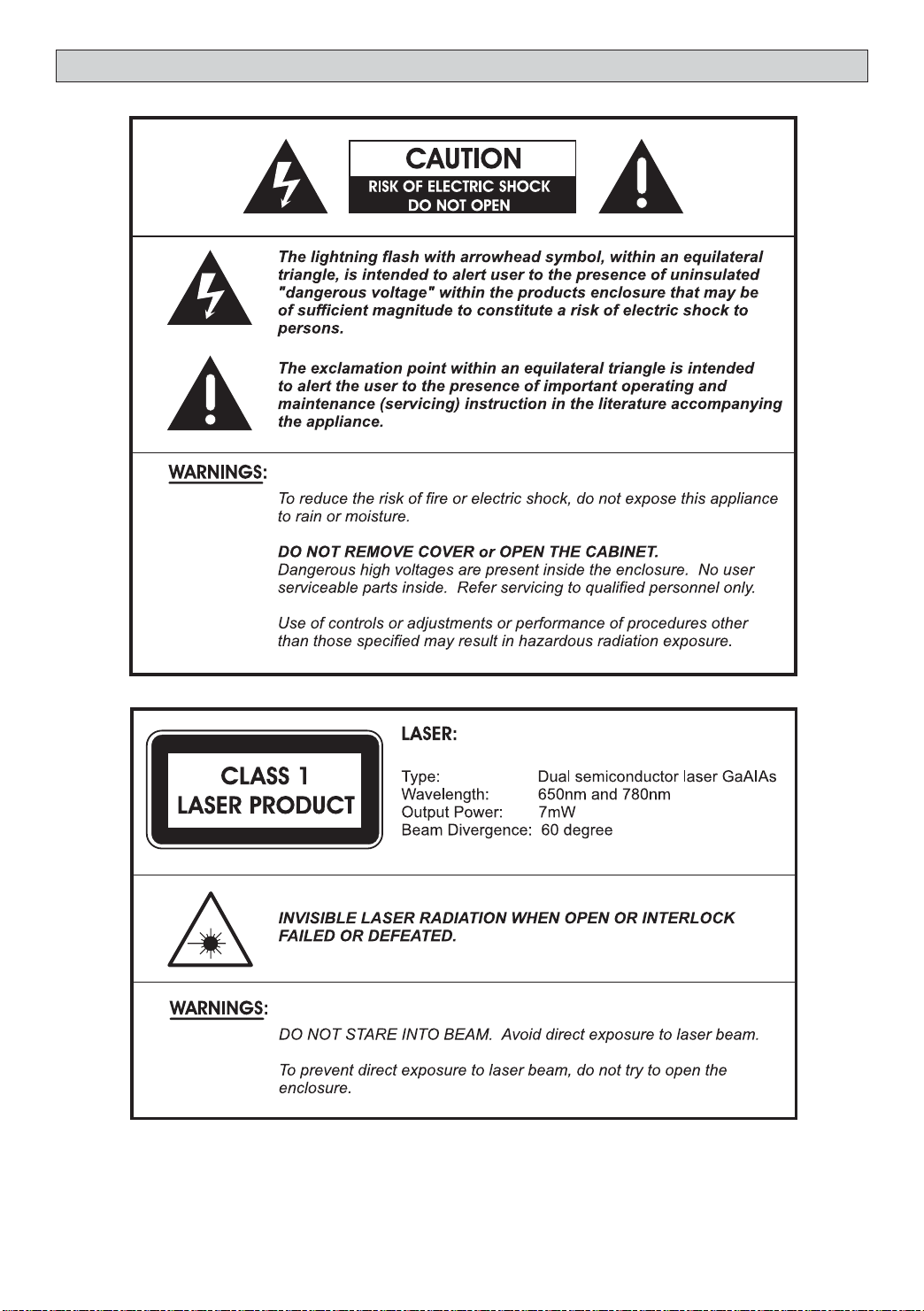
IMPORTANT SAFETY INSTRUCTIONS
CAUTION: RETAIN THIS BOOKLET FOR FUTURE REFERENCE.
This set has been designed and manufactured to assure personal safety. Improper use can result in electric
shock or fire hazard. The safeguards incorporated in this unit will protect you if you observe the following
procedures for installation, use and servicing. This unit does not contain any parts that can be repaired by the
user.
• Read these instructions.
• Keep these instructions.
• Heed all warnings.
• Follow all instructions.
• Do not use this apparatus near
water.
• Clean only with dry cloth.
• Do not block any ventilation
openings. Install in accordance
with the manufacturer’s
instructions.
• Do not install near any heat
sources such as radiators, heat
registers, stoves, or other
apparatus (including amplifiers)
that produce heat.
• Do not defeat the safety purpose
of the polarized or grounding-type
plug. A polarized plug has two
blades, one wider than the other.
A grounding type plug has two
blades and a third grounding
prong. The wide blade or the third
prong is provided for your safety.
If the provided plug does not fit
into your outlet, consult an
electrician for replacement of the
obsolete outlet.
• Protect the power cord from
being walked on or pinched
particularly at plugs, convenience
receptacles and the point where
they exit from the apparatus.
• Only use attachments/
accessories specified by the
manufacturer.
• Unplug this apparatus during
lightning storms or when unused
for long periods of time.
apparatus. When a cart is used,
use caution when moving the cart/
apparatus combination to avoid
injury from tip-over.
• Refer all servicing to qualified
service personnel. Servicing is
required when the apparatus has
been damaged in any way, such as
when the power supply cord or
plug is damaged, liquid has been
spilled or objects have fallen into
the apparatus, the apparatus has
been exposed to rain or moisture,
does not operate normally, or has
been dropped.
• Apparatus shall not be exposed
to dripping or splashing and that
no objects filled with liquids, such
as vases, shall be placed on the
apparatus.
• Disc Tray
Keep your fingers well clear of the
disc tray as it is closing. It may
cause serious personal injury.
• Burden
Do not place a heavy object on, or
step on the product. The object
may fall, causing serious personal
injury and serious damage to the
product.
• Disc
Do not use a cracked, deformed,
or repaired disc. These discs are
easily broken and may cause
serious personal injury and
product malfunction.
qualified service personnel under
the following conditions:
a) When the power-supply cord or
plug is damaged.
b) If liquid has been spilled, or ob-
jects have fallen into the product.
c) If the product has been exposed
to rain or water.
d) If the product does not operate
normally by following the operating instructions. Adjust only those
controls that are covered by the
operating instructions. Improper
adjustment of other controls may
result in damage and will often
require extensive work by a qualified technician to restore the product to its normal operation.
e) If the product has been dropped
or damaged in any way.
f) When the product exhibits a dis-
tinct change in performance - this
indicates a need for service.
• Servicing
Do not attempt to service this
product yourself as opening or
removing covers may expose you
to dangerous voltage or other
hazards. Refer all servicing to
qualified service personnel.
• Replacement Parts
When replacement parts are
required, be sure the service
technician has used replacement
parts specified by the
manufacturer or have the same
characteristics as the original
part. Unauthorized substitutions
may result in fire, electric shock,
or other hazards.
• Safety Check
Upon completion of any service or
repairs to this product, ask the
service technician to perform
safety checks to determine that
the product is in proper operating
condition.
• USA & Canada versions comply
with ETL requirements.
• Use only with a cart, stand, tripod,
bracket or table specified by the
manufacturer, or sold with the
• Damage Requiring Service
Unplug this product from the wall
outlet and refer servicing to
2
Page 4

Contents
Introduction
Safety ................................................................................................................... 1
Important Safety Instructions ................................................................................... 2
Contents, Packing ................................................................................................... 3
Player Zones, Anti-copy Disc Protection, Installation ..................................................... 4
DVD Discs & Cleaning DVD Discs ............................................................................. 4
Remote Control ...................................................................................................... 5
Front Panel ............................................................................................................ 6
Rear Panel ............................................................................................................. 7
Connections
Setup and Installation - Video Connections ................................................................... 9
Audio Connections, Speaker Connections .................................................................... 10
Speaker Placement ................................................................................................. 12
Switch on for the first time, Special on screen message ................................................ 12
Function Setup
Basic Operations .................................................................................................... 13
Play, Play Mode, Lock ............................................................................................... 14
Display ................................................................................................................. 15
Sound ................................................................................................................... 16
Language .............................................................................................................. 18
Basic Playback
General Operation ................................................................................................... 19
Surround Sound & Surround Effects ........................................................................... 20
Radio.................................................................................................................................... 21
Sleep.................................................................................................................................... 22
Playing DVD/CDs .................................................................................................... 22
When DVD/CD Disc is playing ................................................................................... 22
Playing MP3/WMA/JPEG/MEPG4 Discs ...................................................................... 24
Selections Menu ..................................................................................................... 24
When disc is playing ................................................................................................ 24
Problems
Disc you can play .................................................................................................... 26
Problems? ............................................................................................................. 28
Service Information ................................................................................................. 29
Warranty............................................................................................................... 30
NOTE : This equipment has been tested and found to comply with the limits for a Class B digital device, pursuant to part 15 of the FCC Rules.
These limits are designed to provide reasonable protection against harmful interference in a residential installation. This equipment generates,
uses and can radiate radio frequency energy and, if not installed and used in accordance with the instructions, may cause harmful interference
to radio communications. However, there is no guarantee that interference will not occur in a particular inst allation. If thi s equipment does cause
harmful interference to radio or television reception, which can be determined by turning the equipment off and on, the user is encouraged to try
to correct the interference by one or more of the following measures:
- Reorient or relocate the receiving antenna.
- Increase the separation between the equipment and receiver.
- Connect the equipment to a supply outlet different from that to which the receiver is connected.
- Consult the dealer or an experienced radio/TV technician for help.
This product incorporates copyright protection technology that is protected by U.S. patents
and other intellectual property rights. Use of this copyright protection technology must be
authorized by Macrovision, and is intended for home and other limited viewing uses only
unless otherwise authorized by Macrovision. Reverse engineering or disassembly is
prohibited.
U.S. Patent Nos. 4,631,603; 4,819,098; 4,907,093; 5,315,448; and 6,516,132.
Consumers should note that not all high definition television sets are fully compatible with this
product and may cause artifacts to be displayed in the picture. In case of 525 or 625 progressive
scan picture problems, it is recommended that the user switch the connection to the “standard
definition” output. If there are questions regarding our TV set compatibility with this model 525p and
625p DVD player, please contact our customer service center.
Manufactured under license from Dolby Laboratories. “Dolby”, “Pro Logic” and the double-D
symbol are trademarks of Dolby Laboratories.
Packing
Check the contents of the box of your DVD Receiver.
There should be the following:
• DVD Receiver with attached power cord
• Remote Control with 2 batteries
• Owner’s Manual
• Audio / Video Cable
• AM antenna and FM antenna
• Subwoofer with connection cable
• 2 front speakers with wire
• Center speaker with wire
• 2 rear speakers with wire
3
Page 5
Player Zones
For the purpose of distribution of DVD Discs, the world has been separated into 6
zones. The zone your unit is intended for is indicated on the Zone Label. This should
be the same as the label on discs available in your region. If you have any difficulties in
playing a disc, make sure that the disc is for the same zone as your player.
Region 1
Anti-copy Disc Protection
Some DVD discs have anti-copying devices.
With these discs the playback on a Television will give the highest quality picture, however you will not be able to
record this signal on a VCR.
Installation
Install your unit on a stable flat surface. There must be sufficient room in front of the unit for the drawer to be
opened and the unit should be positioned so that it can see the remote control.
Do not expose your unit to extremes of temperature or humidity. Avoid standing it on a hot surface such as on
top of other hot running equipment and ensure that there is adequate ventilation to the unit.
* Caution : Do not install this equipment in confined space such as a book case or similar unit!
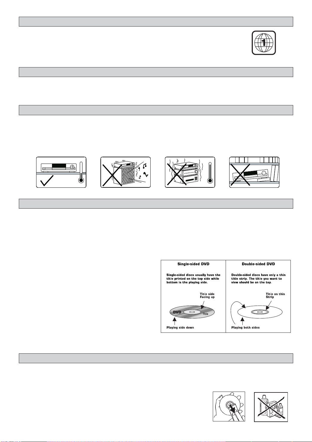
DVD Discs
There are several types of DVD Disc.
Single sided discs. They play for approximately 2 HOURS
Single sided two layer discs. They play for approximately 4 HOURS
Double sided discs. They play for approximately 4 HOURS
Double sided with 2 layers on both sides. They play for approximately 8 HOURS
DVD discs have Titles and Chapters. There can be several Titles on one disc and each Title can contain several
Chapters. Titles and Chapters are numbered, e.g. Title 1, Title 2 etc. & Chapter 1,2,3 etc.
Usually Title one will show the disc publisher and studio
logos. The next Title will be the film. Other Titles
contain trailers for other films, production notes, or
alternative endings for the film. There are many
possibilities with Digital Versatile Disc. Chapters within
the main Title allow you to search quickly for a specific
point on the disc. Many discs have a Chapter Menu
sometimes called Scene Index or Scene Menu that
displays the first shot from each Chapter, which allows
you to select a shot and play the disc from that point
onwards. DVD discs can be PAL or NTSC. This player
can play both types (if the player zone is correct).
DVD discs allow up to 8 Languages and 32 subtitles on a single disc. You can select and change the language
and subtitle to suit yourself and play the whole disc or just part of it and view it from different angles.
Cleaning DVD Discs
Picture freezing & sound skipping or repeating can occur if the disc inside the player is dirty.
• When a disc becomes dirty, clean it with a cleaning cloth. Wipe the disc from the center out.
• Do not wipe in a circular motion. Circular scratches can cause picture distortion or render the disc
unplayable.
CAUTION - Do not use solvents, commercially viable cleaners, or
antistatic spray intended for analog discs.
4
Page 6
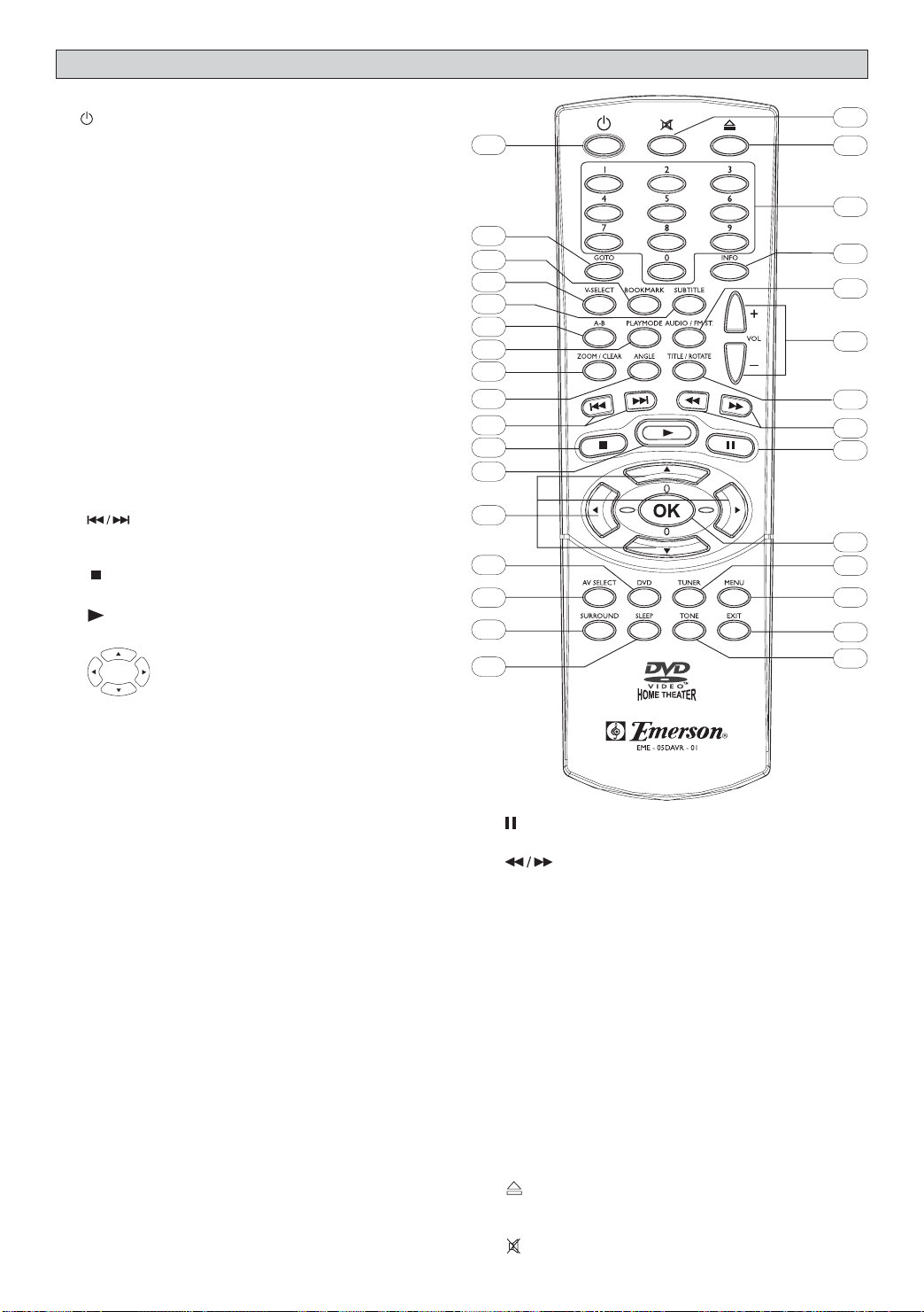
Remote Control
1. ON/STANDBY turns unit on/standby
2. GOTO display Time menu
3. BOOKMARK open bookmark menu of disc
4. V-SELECT toggle between Progressive Scan
and switching different video output modes.
5. SUBTITLE display Subtitle menu
6. A-B display the Repeat A-B info menu
7. PLAYMODE display Playmode menu
8. ZOOM selects Zooming options when playing
video disc by pressing repeatedly CLEAR
delete the last selection in Program mode
9. ANGLE display Angle menu if present on discs
10. skip backward/forward to the previous
or next chapter/track.
stops playing
11.
12.
starts playing
13. (Active Navigation keys) advance
in indicated directions for making
selections in menus, Active
Navigation mode and tuner
settings.
10
11
12
13
14
15
16
17
31
1
2
3
4
5
6
7
8
9
30
29
28
27
26
25
24
23
22
21
20
19
18
14. DVD selects DVD/CD mode.
15. AV SELECT selects external AV inputs
(press repeatedly).
16. SURROUND selects Surround modes or
Soundfield modes.
17. SLEEP sets the Sleep (auto-off) timer
function.
18. TONE selects EQ modes.
19. EXIT exits menus and Active Navigation mode.
20. MENU 1) enters Disc Contents Menu in DVD
mode, 2) enters System Setup for SPEAKER
settings in all other modes.
21. TUNER selects Tuner mode, switches between
AM and FM bands.
22. OK 1) enters or selects in menu and setup
navigation, 2) in Tuner mode, enters
preset programming mode or confirms a
preset.
23.
freezes picture and sound during play
24.
start reverse or forward search.
25. TITLE (ROTATE) 1) displays the Title Menu if
present on disc (DVD mode only), 2) rotates
pictures when playing Picture CDs.
26. -VOL+ increases or decreases the volume.
27. AUDIO/FM ST selects Mono / Stereo in Tuner
mode.
28. INFO enters or exits Active Navigation mode.
29. 0 - 9 (Numeric keys) used for direct selections
of Title, Chapter, Track, Tuner, Channel and Time
search input in DVD mode.
OPEN/CLOSE opens or closes the disc
30.
tray.
31. MUTE mutes and Restores sound output.
5
Page 7
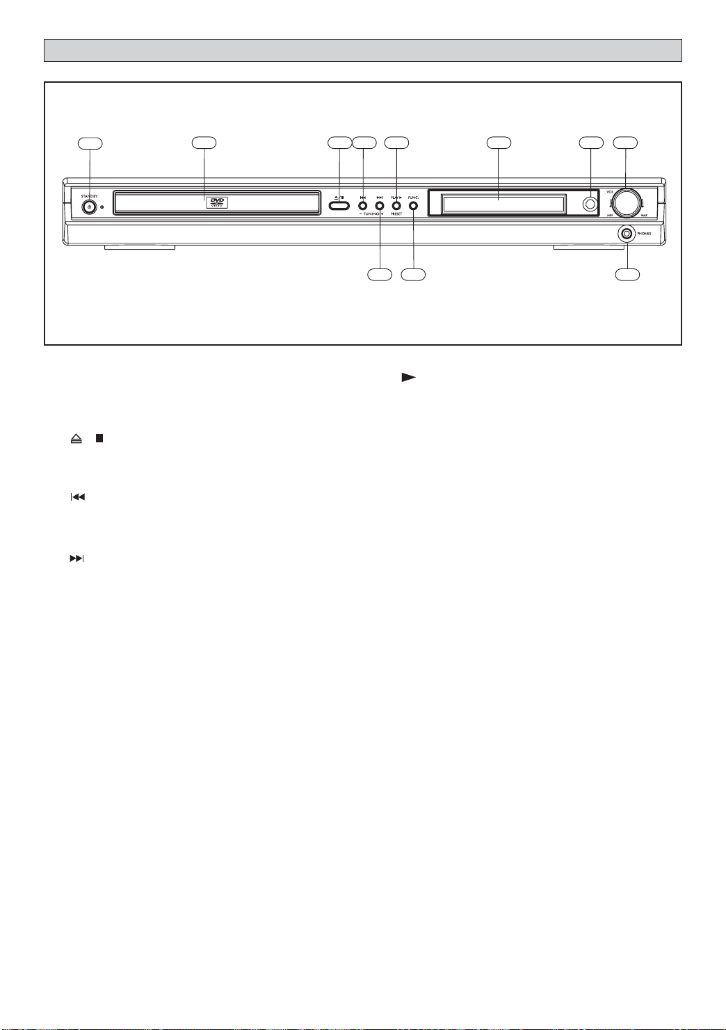
Front Panel
1
2 3 5
1. Standby On / Off
2. Disc Tray
3. / 1) Opens or closes the disc loading
tray in Stop or No Disc mode, 2) Stops
playing.
4.
SKIP 1) skips to previous chapter/track
in DVD/CD mode, 2) tunes to a lower
frequency in Tuner mode.
5.
SKIP 1) skips to next chapter/track in
DVD/CD mode, 2) tunes to a higher
frequency in Tuner mode.
7
6
4
98
10
11
6. 1) Starts playing in DVD/CD mode, 2) Saves
preset channel mode in Tuner mode.
7. FUNC. Switches between AV mode, Tuner
mode, AUX mode and DVD mode.
8. VFD Display
9. Infra-Red Receiver Window
10. VOLUME Adjusts the master volume. Turn
clockwise to increase the volume and counterclockwise to decrease the volume.
11. Headphone Jack
6
Page 8

Rear Panel
1
13
14
6
11
10
9
12
354
2
7
AC120V~ 60Hz 200 Watts
8
IMPORTANT!
Connect the AC cord only after the speakers, antenna and all optional equipment have been
connected.
Never make or change any connections with the power switched on.
The rating plate is located at the rear panel of the system.
1. FM Antenna Input Connections
For FM reception, connect the FM antenna to the FM jack. Move the antenna in various directions until
the clearest signal is received.
AM Loop Antenna Connections
For AM reception, connect the AM loop antenna to the AM jack. Position the loop antenna to receive the
clearest sound.
1
2
Fully insert the stripped portion of the antenna into the terminal as shown above.
Note: Position the antenna as far away as possible from a TV, VCR or other radiation source.
2. Audio Inputs
For connecting audio (Left / Right) input signals from auxiliary sources such as VCR, TV or Satellite
Receiver and playing them through this Home Theater System. These connections are labelled AUX1 and
AUX2 and are selected by the FUNC. button on the front panel.
3. Video Inputs
For connecting video signals from the corresponding video out jacks on the axillary items, such as a TV,
VCR or satellite receiver.
4. Video Output - VCR
For connecting VCR or other recording device (Most DVDs cannot be recorded, however you can use
this connection to record from the auxiliary inputs, such as a satellite receiver, as well).
5. Audio Outputs - VCR
For connecting audio (Left / Right) signals to external recording devices such as VCR or Tape Recorder.
6. Component Video & Progressive Outputs
For connecting TV with component video input (using component video cable, not provided).
7
Page 9

Rear Panel
7. Digital Coaxial Audio Output
For connecting external equipment that has digital audio input jack, such as an External Decoder.(Coaxial
Cable not included)
8. S - Video Output
For connecting the S-VIDEO IN jack on the TV using an optional S-Video cable. This type of connection will
provide superior picture quality. However, your TV must be equipped with an S-Video input socket.
9. Surround Speaker (Rear Speakers)
For connecting the left surround speaker to “SL” terminals and right surround speaker to “SR” terminals.
Connect the colored wire to “+” and black wire to “-”.
10. Subwoofer Speaker
For connecting the passive subwoofer, with colored wire to “+” terminal and black wire to “-” terminal.
11. Center Speaker
For connecting the center speaker, with colored wire to “+” terminal and black wire to “-” terminal.
12. Front Speaker
For connecting the left front speaker to “L” terminals, right front speaker to “R” terminals. Connect the
colored wire to “+” and black wire to “-”.
13. Active Subwoofer Out
For connecting an optional external powered subwoofer (not included).
14. Power Cord
8
Page 10
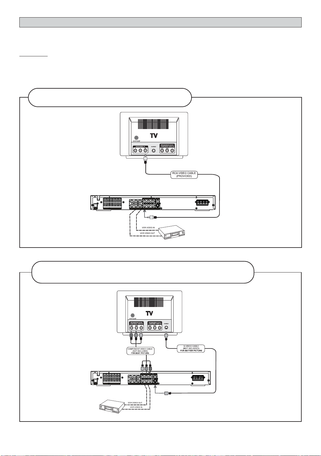
Setup and Installation
The following setup and installation diagrams show the different video and audio connections to TV, VCR or CD
Recorder.
Important
Make sure the AC Voltage matches your local voltage.
Connect the AC cord only after the speakers, antennas, and all optional equipment have been
connected.
(1) Video Connections
For good picture quality, use the RCA VIDEO CABLE
(Included)
NOTE: Not all TVs have S-Video or Component Video Input jacks.
For better picture quality, use S-VIDEO CABLE (not included). For best picture
quality, use COMPONENT VIDEO CABLE (not included)
NOTE: When in AV1 or AV2 mode, only composite video sources will have video output signal, therefore, connect
only RCA video output or TV Out to your TV sets.
9
Page 11

(2) Audio Connections
VCR
AUDIO IN
VCR
AUDIO OUT
TV AUDIO OUT
Example: EXTERNAL DECODER
(OPTIONAL)
COAXIAL IN
VCR
AUDIO OUT
TV AUDIO OUT
Example: EXTERNAL DECODER
VCR
AUDIO IN
(OPTIONAL)
COAXIAL IN
(3) Speaker connections
Before Connecting
This DVD Receiver is designed to reproduce optimum sound quality when the supplied speakers are used. If you
wish to connect other speakers to the system instead of the supplied speakers, they should be 4 ohms
impedance.
Maintain correct polarity when connecting speakers (colored wire for positive and black wire for negative).
To prevent damage to circuits, never short-circuit the positive and negative speaker output terminals.
SUBWOOFER
(Can be placed
anywhere in the room)
5
SURROUND
RIGHT SPEAKER (Rear)
2
FRONT RIGHT
SPEAKER
3
CENTER
SPEAKER (Front)
1
FRONT LEFT
SPEAKER
4
SURROUND
LEFT SPEAKER (Rear)
10
Page 12

The above connections can be expressed by the below table:
SPEAKERS
Unit
Terminals
Use Wires
Insert the wire to the jack behind of the Speaker.
Connection of all speakers are the same.
FRONT LEFT FRONT RIGHT CENTER
L+
White
L -
BlackR+Red
Note: always connect colored wire to colored speaker terminal (+).
R -
Black
always connect black wire to black speaker terminal (-).
Green
C+
C -
Black
SURROUND
LEFT (REAR)
SL+
Blue
SL -
Black
SURROUND
RIGHT (REAR)
SR+
Grey
SR -
Black
Notes
• Do not remove
excessive amount of
insulation on the wire
cords, to avoid the
stripped portion from
touching each other. The
optimal length for the
stripped part should be
around 1/3 inch (or
1cm).
• Do not push the
stripped part too far
into the speaker
connectors.
PASSIVE
SUBWOOFER
+
Purple
-
Black
11
Page 13

Speaker Placement
Placement of speakers play an important role in the reproduction of surround sound. Particular attention
should be taken when designing the speaker layout. For the best surround effects, all speakers should be
installed.
Front
speaker
( left )
Rear speaker
( left surround )
Subwoofer
Center Speaker
TV
VIEWING AREA
Front
speaker
( right )
Rear speaker
( right surround )
Front
speaker
(left)
DIM L
Rear speaker
( left surround )
Subwoofer
Center Speaker
TV
DIM C
DIM R
DIM RSDIM LS
Front
speaker
( right )
Rear speaker
( right surround )
A typical room layout will have the left, center, and right speakers placed across the front and the left surround
and right surround speakers placed along the sides towards the rear as shown in the above left picture. The
center speaker can be positioned above or below the video screen or TV. A subwoofer can be installed for
powerful bass sounds and can be positioned anywhere in the room.
The ‘speaker to listener dimensions’ shown in the above right picture is used for proper setup of the surround
system (
Please refer to Speaker Setup on P.16
).
Note:
• Do not connect more than one speaker to any one pair of +/- speaker terminals.
• Do not connect speakers with an impedance lower than the speakers supplied.
Switch on for the First Time
• You have connected and set up the Home Theater System as shown in the preceding pages.
• Connect Power to the DVD Player.
• The DVD Player should have the Standby Light illuminated.
• Press the Power on key (either on the panel or the remote control), the player will be in AV 1 mode.
• Press DVD (either on the panel or the remote control), the DVD Player will switch on in DVD mode. After
a few seconds the panel will show “NO DISC”.
• Switch on your TV and select the AV input that the DVD Player is connected to. You should see the DVD
Screen and a message “Insert a disc”.
• Press the open key (on the panel or the remote control). The drawer will open. Place a DVD in the drawer,
and press close (same as open). The player will read the disc and start playing it. Before the movie starts
to play, a menu will be shown. You will need to select ‘PLAY MOVIE’ and press [OK] before the movie will
start.
• Although you can watch a movie immediately, to get the best result from your Home Theater, you should
now press ‘STOP’ and proceed to do the system setup options on the next page. This will set up all the
functions on your theater. You only need to do this when you first install your Home Theater.
• If you choose to watch the movie you can find out about DVD options and navigation of the DVD disc in the
section “Playing a DVD disc” and onward.
Special On Screen Message
This symbol when displayed, means that the key you have pressed is not available at this time, or
that this action is not allowed by the disc at this time.
12
Page 14

Function Setup
Proper setup of the unit will let you enjoy better sound and picture quality as well as many useful features. The
selections are the preferred options that will be chosen, provided they are available on the disc. NOTE: If the
disc loaded does not have the preferred option then the disc’s own preference should be used.
BASIC OPERATIONS
To access the setup menu the unit must be in STOP mode.
Play
Play Mode
Lock
Display
Sound
Languages
Insert a disc
Use the Active Navigation keys to browse and make selections in the menus.
To make selections within a menu, press
and then OK
Play
Play Mode
A parent menu exists,
press or EXIT
Lock
Display
Sound
Languages
Player Menus
Disc Menus
Audio
Subtitles
English
English
English
English
A root menu exists,
press or OK.
Example shows how to select “French” as “Disc menus” language in the “Languages” menu.
Select
“Languages”
Play
Play Mode
Lock
Display
Sound
Languages
Play
Play Mode
Lock
Display
Sound
Languages
Insert a disc
Player Menus
Disc Menus
Audio
Subtitles
x5
English
French
English
English
“Languages”
Play
Play Mode
Lock
Display
Sound
Languages
Select “French” Open “Disc Menus”Confirm “French”
Player Menus
Disc Menus
Audio
Subtitles
Open
Player Menus
Disc Menus
Audio
Subtitles
Portuguese
English
French
Spanish
German
Italian
Swedish
English
English
English
English
Select “Disc Menus”
Play
Play Mode
Lock
Display
Sound
Languages
Player Menus
Disc Menus
Audio
Subtitles
Player Menus
Disc Menus
Audio
Subtitles
English
English
English
English
English
French
Spanish
German
Portuguese
Italian
Swedish
13
Page 15

PLAY
Play
PLAY MODE
Play Mode
LOCK
Enter New Password
OK
Play
No menu is available without disc loaded. (See under “When DVD is stopped”
or “When CD is stopped”)
Play Mode
No menu available without disc loaded. (See under “When DVD is stopped” or
“When CD is stopped”)
Lock Player
Create your password here using the numeric keys. The player is delivered
without a password. When you set the rating limits (see under “Rated
Titles”) for the first time, you are required to enter your own password (e.g.
1,2,3,4). This becomes the password for the unit. You must memorize this
password in order to change it in future.
Enter New Password
OK
Change Password
Change your existing password to a new one using the numeric keys to
replace the existing one.
Rated Titles
DVD discs have parental levels assigned to them. The range of parental
controls are from 1 to 8.
The player can be set in a similar way by pressing
unit’s rating limit is set to 8, it will play all discs. If the player’s rating limit is
set below 8, only discs with a lower or equal parental level will play.
For example if the player is set to 5, only discs with parental control ratings
of 5,4,3,2, & 1 will play. To play a higher rated disc you must change the
unit’s rating to a higher number.
. If the
14
Page 16

DISPLAY
Component
S-Video
4 x 3 Letterbox
4 x 3 Standard
16x9Widescreen
4x3 Letterbox
NTSC
Off
Component
Display
TV Image
PAL/NTSC
Progressive Scan
Progressive Scan
Video
TV Image
Three options available: 1) 4x3 Letter Box, 2) 4x3 Standard & 3) 16x9 Wide
Screen. Press OK to select a suitable one.
Select TV Image according to your TV type.
If you have a wide-screen (16:9) TV, select “16x9 Widescreen”
- for 16:9 movie, you will have full screen viewing.
- for 4:3 movie, black bars show on left and right sides of screen.
For conventional 4:3 TV,
- if you select 4x3 Letter Box for 16:9 movie, black bars show on top and
bottom of screen.
- if you select 4x3 Standard for 16:9 movie, left and right edges of the
screen are hidden.
- if you select either 4x3 Letter Box or 4x3 Standard for 4:3 movie, you will
have full screen viewing.
PAL/NTSC
Press OK to select between PAL or NTSC output to match your TV or other
equipment.
The setting will change to Progressive Scan ON.
Incorrect setting of this item can distort the picture or no video
can be observed after proceeding this step. Toretrieve correct
video output, you can press V.SELECT key several times.
Do you want to continue?
No, switch to Component output.
Yes, switch to Progressive Scan output.
Does your TV support Progressive Scan mode? and
Have you connected the Component Video Output cable to your TV
and your TV has set up accordingly?
No
Yes
Progressive Scan
By displaying all the lines of a picture simultaneously (instead of displaying odd
and even lines alternatively such as a conventional TV), Progressive Scan greatly
enhances picture resolution while minimizing distortion and flickering. To use
this feature, your TV must be Progressive Scan compatible with
Component Video input jacks connected to the DVD unit.
1. Set your unit to PAL output mode.
2. Select the Progressive Scan option and press OK (or V.Select on the
remote control) to activate.
3. A caution message will display. Press OK to continue.
Caution: If you see distorted or no picture after pressed OK, then check the following:
i) Your TV may not be Progressive Scan compatible. Wait a few seconds and
the unit will have return to the previous setting automatically.
ii) Make sure your TV is connected with Component Video output from the DVD
unit and is now switched to view such input through which Progressive Scan
signals are transmitted . There will be no video signal from AV output, in case
you have both Component Video and AV connections.
4. A message requesting for confirmation will appear on screen. Select Yes
(confirm) or No (return to previous setting) by
and press
OK to confirm.
Video Output
Press OK to select between Component Output, and S-Video output to
match the video output of your DVD unit.
15
Page 17

SOUND
DRC
Digital Output
Speaker Setup
Sound
OFF
ON
Dynamic Range Compression (DRC)
Press OK to turn on/off. This controls the Dynamic Range Compression
(DRC) for night time listening. DRC reduces the difference between normal
voices and sounds such as like explosion to avoid waking your neighbours.
The amount of range control available depends on the disc.
Digital Output
Press OK to check the box if you have connected the unit’s digital audio
output to a receiver with Dolby Digital or DTS.
Speaker Setup
Two options are available to adjust your speakers setting to
best fit your listening environment.
Distance
You can specify the distance (changing the sound delay) between
speakers (front, center and surround speakers) and the listener for
optimal stereo sound.
The default distance is 10 feet for front and center speakers and 5
feet for surround speakers. Change the distance from 1 to 30 feet
according to your actual listening environment by pressing
and then OK.
PL II Mode
PL II Control
Speaker Setup
Front
Center
Surround
Music
Distance
Volume
Front Speaker Distance
3 meter
Volume
You can make fine adjustment to the loudness of each speaker from 10 to +10 dB. When this option is selected, a test noise will
generate automatically from each speaker, one by one. To go to the
next speaker manually, press .
Adjust loudness by pressing and press OK to
confirm setting and exit the menu.
16
Distance
Volume
Center Speaker
dB
0
Page 18

Pro Logic
Virtual
Music
Movie
Matrix
Pro Logic II Mode
The additional flexibility of Pro Logic II allows it to be tailored for specific applications.
Five standard modes are available:
Pro Logic - It offers users the robust surround processing of the original
Pro Logic.
Virtual - It’s usually used when Pro Logic II is connected to a virtual
process for speaker use.
Music - It’s recommended as the standard mode for autosound music
systems (without video), and is optional for A/V systems.
Movie - It can be called simply “Pro Logic II”. It has stereo surround
channels and no surround filter, unlike Pro Logic which has a
mono surround channels and a 7KHz surround filter. Movie
mode is the standard required for all A/V systems.
Matrix - It’s the same as the Music mode except that the directional
enhancement logic is turned off. It may be used to enhance
mono signals by making them seem “larger”.
Dimension
Panorama
Center Width
Pro Logic II Control
Off
PL II Control lets you to customize the Pro Logic II Music Mode Sound Effect. The
Off
option is available only when the player is in Music Mode.
Off
Dimension
A simple control that alters the ratio of L+R to L-R for the twochannel input signals. It allows the user to gradually adjust the
soundfield either towards the front or towards the rear. If a
recording is too spacious or strong from the surrounds, it can be
adjusted “forward” to get a better balance. Likewise, if a stereo
recording is somewhat too “mono” or “narrow” sounding, it can be
adjusted toward the rear to get a more enveloping, immersing
result.
Panorama
Extends the front stereo image to include the surround
speakers for an exciting “wraparound” effect with side-wall
imaging.
Center Width Control
With Pro Logic decoding, dominant center signals can come
only from the center speaker. If no center speaker is present,
the decoder splits the center signals equally to the left and
right speakers to create a “phantom” center image. The
Center Width control allows variable adjustment of the
center image so it may be heard only from the center
speaker; only from the left/right speakers as a phantom
image; or from all three front speakers to varying degrees.
It’s recommended to set the control to use the position 3
values for the Music mode. This will also help distinguish the
Music mode from the Movie mode, which automatically
presets the Center-width control to position 0.
Dimension
Panorama
Center Width
-3
-2
-1
OFF
1
2
3
OFF
ON
OFF
1
2
3
Soft
5
6
7
17
Page 19

LANGUAGES
Player Menus
Select among the 7 languages as default language for player menus. Press
OK to confirm selection.
English
French
Spanish
English
French
Spanish
English
French
Spanish
Disc Menus
Select among the 7 languages (if available on disc) as default language for
disc menus. Press OK to confirm selection.
Audio
Select amongst the 7 languages (if available on disc) as the default audio
language. Press OK to confirm selection.
Subtitle
Select among the 7 languages (if available on disc) as the default subtitle
language. Press OK to confirm selection.
18
Page 20

General Operation
PL II
Selecting the source
Press one of the input selector buttons (on the front panel or remote control) to select the below input source:
- AV SEL (press FUNC. on front panel or AV SEL on remote control)
- TUNER
HzM
- DVD/CD
Adjusting the Master Volume
The master volume adjusts all channels at the same time: Press on the remote control, OR rotate the
master volume knob on the front panel.
Muting the Sound
Press MUTE to mute the speaker output. The Speaker Indicator will disappear on the display and the MUTE
icon appears. Press MUTE or the volume button on the remote or volume knob on the front panel to restore
the speakers output.
Selecting Surround Output Modes
The number of output modes varies according to the system setup and the input sources. Press SURROUND
repeatedly on the remote control to select the different surround modes as shown below:
- Dolby Pro Logic II Surround - 3 Stereo
VIDEO
CH
PL II
L
R
C
SW
RS
LS
- Stereo - Digital Soundfield Simulation - Stadium
CH
L
R
SW
CH
CH
L
R
C
SW
PL
L
R
SW
RS
LS
- Stage - Hall
CH
PL
L
R
SW
RS
LS
CH
19
PL
L
R
SW
RS
LS
Page 21

- Disco - Live
CH
PL
L
R
SW
RS
LS
CH
PL
L
R
SW
RS
LS
Selecting EQ Modes
There are 6 EQ modes available while you are listening to 2 channels output (e.g. Music CD). Press TONE
repeatedly on remote control for selection amongst FLAT, ROCK, POP, CLASSIC, JAZZ, and EXTENDED BASS.
CH
PL
L
R
SW
RS
LS
Surround Sound & Sound Effects
Display Indicators
D
Dolby Digital Indicator
Dolby ProLogic II Indicator
L
R
C
SW
RS
LS
Speaker Indicator
Note: For proper surround sound make sure you have followed the setup and installation procedure
fully.
Dolby Digital Surround
The Dolby Digital Surround system requires connections of all 5 speakers (front left, center, front right,
surround right, surround left) for the correct surround sound reproduction. This 5.1 channel digital surround
format enables five individual full-range (20Hz-20KHz) channels plus an LFE (Low Frequency Effects) channel
for the low-range (20Hz-120Hz) effects. It creates a realistic sound similar to the theaters and cinemas. A
large proportion of DVD discs use this system for sound.
Dolby Pro Logic II Surround
The Dolby Pro Logic II Surround system is the next generation in Dolby Surround decoding. It creates five fullbandwidth output channels from two-channel sources. This is done using an advanced, high-purity matrix
surround decoder that extracts the spatial properties of the original recording without adding any new sounds
or tonal colorations.
3 Stereo
3 Stereo produces three channels (front left, center, front right) of sound from a two channels analog signal. It
is not a surround format so it does not require surround speakers.
Soundfield Effects
The digital Soundfield Effects recreates the effects of sounds reflected from walls or ceilings to obtain the
sound presence of real environments.
- Stadium: recreates a large stadium using very long reverberation times.
- Stage: recreates a stage environment, emphasizing sound from the front speakers.
- Hall: recreates a hall using lots of reflections. Suitable for orchestral music such as classical and opera.
- Disco: recreates the disco or club music effect. It is suitable for all types of music that are played in
disco.
- Live: suitable for all types of music.
20
Page 22

Radio
Display Indicators
Stereo Indicator
ST
K
MHzHz
AM Frequency Indicator
Tuning
FM Frequency Indicator
Manually
1. Press TUNER to select tuner mode, the display will change to show the current band and frequency.
HzM
2. Press
or / on the Front Panel or use the remote’s numeric keys to change the
frequency.
Automatic tuning
1. Press TUNER to select tuner mode.
2. After two seconds the display will change to show the current band and frequency.
3. Press and hold
or for more than one second to activate auto tuning mode. When a
station is reached, auto tuning will stop.
Tuning to a weak FM stations
1. Press
to tune in a weak FM station manually.
MHz
2. Press AUDIO/FM ST on the remote control to switch to Mono mode. This will normally improve the
reception, but the sound will no longer be in stereo.
Preset Stations
When a preset station is selected, the preset number will appear next to the frequency on the display.
Selecting Preset Stations
1. In tuner mode, press TUNER to switch between AM and FM band if necessary.
MHz
2. Press OK, then use the remote’s numeric keys or to select desired preset station.
Storing Preset Stations
The unit can store up to 20 stations in the FM and AM wavebands respectively.
1. In tuner mode, press TUNER to switch between AM and FM band.
HzM
Storing Preset Stations
The unit can store up to 20 stations in the FM and AM wavebands respectively.
1. In tuner mode, press TUNER to switch between AM and FM band.
HzM
21
Page 23

2. Press and hold OK until the preset channel icon flashes.
3. Press or use the remote’s numeric keys to select the preset channel number .
4. Press OK once more to store into memory when “SAVED” icon flashes.
HzM
Sleep
Setting the Sleep Timer.
This feature allows you to select a time for the system to switch to the Standby mode automatically.
1. Press SLEEP on the remote control repeatedly to cycle through the below sleep timer options.
The available options are :
SLEEP OFF -> SLEEP 120 -> SLEEP 90 -> SLEEP 60 -> SLEEP 30 -> SLEEP 15
2. The ‘SLEEP’ icon will appear when the desired Sleep time is set on.
Checking remaining Sleep Time
When the Sleep timer is switched on, you can check the remaining time before the unit switches to Standby
mode. Press SLEEP once, the remaining time will be displayed.
Cancelling the Sleep Timer
To switch off the Sleep Timer, press SLEEP repeatedly until “SLEEP OFF” is displayed.
Playing DVD/CDs
1. To play DVD/CD disc, press to open the disc tray.
2. Load disc onto the tray with the label side facing upward.
3. Press
playing while the player reads the menu from the disc.
to close the tray. The disc will start playing automatically. There may be a short delay before
When DVD/CD Disc is playing
Pause, Slow Motion and Frame-by-Frame Advance
Press to freeze playing temporarily. Press repeatedly to select between “Pause” and “Freeze” modes. In the
“Pause” mode, press
pressing repeatedly). In “Freeze” mode, each press of will move the play forward/
backward by one frame. Press
Skip
Press to skip forward or backward a chapter.
Fast Search
Press to search through the disc forward or backward quickly. Pressing will increase/
decrease the search speed.
(Note: there is no sound in Fast Search, Slow Motion and Frame-by-frame Advance modes. Press
resume normal playing.)
to start forward/backward slow motion play ( increase or decrease speed by
to resume normal playing.
to
22
Page 24

Quick keys (MENU, TITLE)
Press corresponding keys to go into their respective disc menu. Select options in menus with navigation keys
and confirm selection by pressing OK.
Stop and Resume stop
Press once to resume stop. In this mode playing can be resumed from the stop point by pressing .
Press
twice to stop playing completely and press will start playing from the beginning.
Numeric keys (0-9) for CD Playing
Input track number for direct track selection.
Active Navigation
Press INFO to display the control bar on TV screen to make menu selections without interrupting playing.
Select options by pressing . Press INFO or EXIT to quit from showing the control bar.
For DVD Discs:
PLAY
00:33:10
For CD Discs:
00:33:10
T:01T:01
C:12
Input the desired time you want to play from, by using the numeric key. Associated scene
will be played on screen.
Press
Press to select the chapter of DVD you want to play.
Press
to the availability on disc.
Press
T:01T:01
C:12
to select the title/track you want to play.
to select the screen fit option [Normal,Enhanced or Maximum] according
to select subtitle language according to the availability on disc.
Press to select audio output mode according to the availability on disc.
Press
repeatedly to select play mode and repeat mode as below:
For DVD disc:
Standard > Program > Random > Disc Repeat > Title
Repeat > Chapter Repeat > Repeat A-B
For CD disc:
Standard > Program > Random > Disc Repeat > Track
Repeat > Repeat A-B > IntroScan
Press OK to enter Index mode and index menu will be display on top of screen. Press OK during
playing to set any scene as indexed. To play/cancel indexes, use the Active Navigation keys to
select
(Play) or (Cancel) in an index and press OK.
23
Page 25

Angle
Playing MP3 / WMA /JPEG/ MPEG4 Disc
1. To play MP3/WMA/MPEG4 disc, press to open the disc tray.
2. Load disc onto the tray with label side facing upward.
3. Press
to close the tray, then the files in disc will be detected.
Selections Menu
MP3 / WMA files only:
The player begins playing all the files in the currently selected folder, and then follow by all the files in the subfolders
contained within its parent folder. After that, the player plays the remaining folders in the disc.
Note: MP3/WMA dosen’t support any surround mode.
JPEG files only:
The player starts the slideshow with the JPEG files currently selected and proceeds to display all the JPEG files
in the same folder. It then goes onto the JPEG files in the subfolders contained in the same folder.
MP3 files along with JPEG files:
The player begins the slideshow with the JPEG files in the currently selected folder. At the same time, it plays
the selected MP3 file, following the music-only playback. The slideshow stops when the picture playback has
finished. If all the MP3 files are finished before the end of the slide show, it will play the first MP3 files again until
the end of the slideshow.
Note: If you haven’t confirmed a selection, the player will automatically play the first 10 seconds of
the track you select.
When disc is playing
Pause
Press to stop playing temporarily. Press again to resume playing.
Skip
Press to skip forward or backward a track.
24
Page 26

Stop and Resume Stop
Press once to Resume Stop. In this mode playing can be resumed from the stop point by pressing .
Press
twice to stop playing completely and press will start playing from the beginning.
Quick keys (ROTATE, MENU, ZOOM)
Press corresponding keys to go into respective disc menu. Select options in menus with navigation keys
and confirm selection by pressing OK. Each press of ROTATE will rotate the picture by 90 degrees. Press MENU
during music playback to display the music selection menu without interrupting playback. Press MENU during
picture/music or picture only playback to display the picture/music selection menu, while playback stops. Press
ZOOM to zoom the picture in and out during a picture slideshow.
Active Navigation
Press INFO to display the info bar on TV screen to make menu selections without interrupting the playing.
MP3 / WMA files only:
Press to select a play mode (Standard, Program, Random, Track Repeat, Folder Repeat, and
Disc Repeat).
PLAY
00:15:20
Play Mode: Standard
MP3
MP3 files along with JPEG files or JPEG files only:
Press
PLAY
00:15:20
MP3
My favorite song
Timer
Display the discs current playback time.
Play Mode Selection
Press
Standard > Program > Random > Track Repeat > Folder Repeat > Disc Repeat
Press OK to confirm.
to select a slideshow speed (Slow, Normal, and Fast).
repeatedly to select play mode and repeat mode as below:
MP3
My favorite song
IMAGE Slideshow Speed: Normal
Timer
Display the discs current playback time.
Slideshow Speed Selection
Press to select a slideshow speed: Fast > Slow > Normal
JPEG
JPEG
My best picture
SSS
SS
MPEG4 files only:
Press
icon is highlighted.
PLAY
00:15:20
to select a subtitle language, audio output mode, and play mode when respective
MPEG4
01 Movie Name
MPEG4 Play Mode: Standard
Timer
Display the discs current playback time.
25
Page 27

Subtitle Selection
Press to select subtitle language according to the availability on disc.
Audio Output Selection
Press to select audio output mode according to the availability on disc.
Play Mode Selection
Press repeatedly to select play mode and repeat mode as below:
Standard > Program > Random > Repeat A-B > Folder Repeat > Disc Repeat >Track
Repeat
Note: When the selection is completed, exit the Navigation Bar by pressing INFO, or EXIT.
PLAYABLE DISC
While advances have been made to ensure that your disc player is compatible with the largest number of discs
possible, however it cannot be guaranteed that you will be able to play discs which might not be compliant with
audio CD standards. In the case of writable and rewritable discs, compatibility with this player depends on the
CD/DVD writer, the right software and the disc used.
DVD-Video
Digital video discs - 5” and 3”, single or double sided,
single or dual layer. DVDs are high-density optical
discs on which high quality picture and audio are
recorded by means of digital signals.
DVD-R, DVD-RW
Most DVD-R and DVD+R (one recording only), DVDRW and DVD+RW discs (rewritable). Depending on
the DVD writer and discs used. Recordings using
DVD-R and DVD-RW discs must be made in Video
DVD mode. Recordings using DVD+RW discs must
be made in accordance with the specifications for
DVD+RW discs with a 4.7 GB capacity.
Audio CD (5” and 3”).
CD-R & CD-RW
Most CD-R (one recording only) and CD-RW discs
(rewritable). This player can play most CD-R discs.
CD-Rs written during a multi-session recording can
also be played, provided that the session has ended
before the disc is played (depending on the write
software). However, depending on the condition of the
CD writer, computer and the disc used, you may find
that not all discs will play successfully. When playing a
CD-R disc, it is completely normal for the unit to take
up to 20 seconds to recognize the disc before starting to play. If the disc is not recognized after a period
of 20 seconds, remove the disc, and then insert it
again.
• Irrespective of the actual recording capacity of
the CD-R, do not use its full capacity.
• CD-Rs should be preferably used instead of CDRWs (rewritable CDs) as, in certain cases, CDRW playback may be faulty.
• Use reliable, good-quality CD write software.
• Close all other applications on the computer to
ensure reliable CD-R disc recording.
MP3 Files
CD-R and CD-RW discs containing audio files in MP3
format. As for CD-R MP3 discs, please follow all the
recommendations for CD-R above, along with the
comments below:
• Your MP3 files should be ISO 9660 or JOLIET
format. ISO 9660 format and Joliet MP3 files are
compatible with Microsoft’s DOS and Windows,
as well as with Apple Mac. These two formats are
the most widely used.
• MP3 filenames should not exceed 12 characters,
and should end with the “.MP3” extension.
General name format: “Title.MP3”. When
composing your title ensure that you use 8
characters or less, have no spaces in the name,
and avoid the use of special characters including (
. , / , \ , = ,+).
• Use a decompression transfer rate of at least
128kB/sec (kilobytes/second) when recording
MP3 files. Sound quality with MP3 files basically
depends on the rate of compression /
decompression you choose. Obtaining audio CD
quality sound requires an analog/digital sampling
rate, that is converted to MP3 format, of at least
128kB/sec and up to 160kB/sec. Choosing higher
rates, such as 192 kB/sec or more, will rarely
produce better sound quality. Conversely, files
with sampling rates below 128kB/sec will not play
properly.
• Do not try recording copyright-protected MP3
files. “Secured” files are encrypted and codeprotected to prevent illegal copying. You must not
copy such files.
Important:
The above recommendations cannot be taken as a
guarantee that the DVD player will play MP3
recordings, or as an assurance of sound quality. You
should note that certain technologies and methods
for MP3 file recording on CD-Rs prevent optimal
playback of these files on your DVD player (i.e.
degraded sound quality and even, in some cases,
inability of the player to read the file).
26
Page 28

PLAYABLE DISC
WMA Files MPEG4 Files
CD-R with WMA files. Windows Media Audio (WMA)
is another compressed audio file format that is
similar to MP3. WMA files can also be grouped in
folders or albums as MP3 files.
• WMA filenames should not exceed 12 characters,
and should end with the “.WMA” extension.
General name format: “Title.WMA”. When
composing your title ensure that you use 8
characters or less, have no spaces in the name,
and avoid the use of special characters including
( . , / , \ , = ,+).
• Use a decompression transfer rate of at least
128kB/sec (kilobytes/second) when recording
WMA files. Sound quality with WMA files basically
depends on the rate of compression /
decompression you choose. Obtaining audio CD
quality sound requires an analog/digital sampling
rate, that is conversion to WMA format, of at
least 32kB/sec and up to 160kB/sec. Choosing
higher rates, such as 192 kB/sec or more, only
rarely produces even better sound quality.
Conversely, files with sampling rates below 32kB/
sec will not play properly.
• Supported Formats: WMA 7.0, WMA 8.0, WMA
9.0.
JPEG Files
For MPEG 4 Video file format, only stereo output will
be available.
As for CD-R MPEG4 discs, please follow all the
recommendations for CD-R above, along with the
comments below:
• Your MPEG4 files should be ISO format without
QPEL.
• MPEG4 filenames should not exceed 12 characters,
and should end with the “.avi” extension. General
name format: “Title.avi”. When composing your title
ensure that you use 8 characters or less, have no
spaces in the name, and avoid the use of special
characters including ( . , / , \ , = ,+).
Important:
The above recommendations cannot be taken as a
guarantee that the DVD player will play MPEG4
recordings, or as an assurance of video quality. You
should note that certain technologies and methods for
MPEG4 file recording on CD-Rs prevent optimal
playback of these files on your DVD player (i.e. In some
cases, inability of the player to read the file, or
playback the file normally).
Depending on the conditions of the recording
equipment or the CD-R/RW, DVD+R/RW or DVD-R/
RW disc itself, some discs can not be played on the
unit.
CD-R and CD-RW with JPEG files. JPEG is a
compressed image file format. Your player can play
JPEG files with a resolution of up to five million (5
mega) pixels. However, there is no perceptible
improvement in the quality of pictures displayed on
your TV screen beyond 400,000 pixels.
Certain JPEG files, including progressive JPEG files,
cannot be read by this player.
Note: Display time will vary according to the file size
and number of pixels of JPEG files.
27
Page 29

PROBLEMS
If it appears that your DVD-Video player is faulty, first consult this checklist. It may be that something simple
has been overlooked.
Under no circumstances should you try to repair the player yourself; as this will invalidate the warranty. Only
qualified service personnel can remove the cover or service this player.
*
When the unit is switched on the first time, SCART will be the defaulted video output. Press the V-SELECT
button to select the correct output modes. Your current output mode will show on the Front Panel Display.
NO POWER
• Check if the on/off button on the front of the player
is set to on.
• Check if plug of the AC cord is properly connected.
• Check if there is power at the AC outlet by
plugging in another appliance.
NO PICTURE
• Check if the TV is switched on.
• Select the correct AV input on the TV.
• Check the video connection.
• Check if channel selector is set to AV on the TV.
(See your TV manual for instructions).
• When Progressive Scan is on, no video output for
composite video output.
• Press the V-SELECT button to select the correct
video output mode. Otherwise no picture or
distorted picture will be found.
DISTORTED PICTURE
• Check the disc for fingerprints and clean with soft
cloth, wiping from center to edge.
• Sometimes a small amount of picture distortion
may appear. This is not a malfunction.
• The disc format does not match the TV-set used
(PAL/NTSC).
• Ensure that ONLY one video output is connected.
THE PLAYER DOES NOT RESPOND TO THE
REMOTE CONTROL
• Aim the remote control directly at the sensor on
the front of the player.
• Avoid all obstacles which may interfere with the
signal path.
• Inspect or replace the batteries.
NO SOUND
• Check audio connections.
• If using a Hi-Fi amplifier, try another sound source.
• Check that DTS digital out is selected in the Audio
Menu if a DTS disc is played.
• Ensure there is a DTS decoder connected when
selecting DTS.
• Clean the disc.
• Check if the disc is defective by trying another disc
NO AUDIO AT DIGITAL OUTPUT
• Check the digital connections
• Check the Digital Out menu to make sure that the
digital output is correctly set.
• Check if the audio format of the selected audio
language matches your unit capabilities.
DISC CANNOT BE PLAYED
• Ensure disc is placed properly into the disc tray.
NO COLOR IN PICTURE
• The disc format is not according to the TV-set
used (PAL/NTSC).
• Ensure DVD player is not connected through VCR.
PICTURE SWING
• Relocate the unit further away from possible
interference or emission source (e.g. Radio, Power
Amplifier, radiator etc.).
NO RETURN TO START-UP SCREEN WHEN
DISC IS REMOVED
• Check to see if the program requires another disc
to be loaded.
• Reset by unplugging the player from the power,
then connect the power again.
YOU HAVE FORGOTTEN THE PASSWORD
• Under no disc condition, press Number Key 7,
Number Key 6, Number Key 4, Number Key 1 and
Number 8 on Remote Control in order.
FUNCTION DISTURBED
• The normal function of the product may be
disturbed by external interference. Just reset the
product (disconnecting and reconnecting the power
cord might be required to resume normal
operation).
28
Page 30

TO FIN D THE LO CATI ON A ND PH ONE
R
NUMBER OF YOUR NEAREST SERVICE
SERVICE
CENTER PERMITTED TO PERFORM
WARRANTY...
CALL TOLL FREE: 1-800-695-0098
FOR ADDITIONAL SET-UP OR OPERATING ASSISTANCE
PLEASE CALL:
1-800-898-9020
FOR CUSTOMER SERVICE, PLEASE WRITE TO:
Emerson Radio Corp.,
Consumer Affairs Dept.,
5101 Statesman Drive,
Irving, TX 75063.
The serial number of your system is located on a label on the back panel.
Please take a moment now to locate the serial number and write the number in the space provided
below. You may be asked to provide this number when calling for product service.
Model Number: AV400
Serial Number:
29
AV400 IB pages.p65 29/4/2005, 15:4529
Page 31

EMERSON RADIO CORP.
LIMITED WARRANTY
What does this warranty cover ? Any manufacturing defects in original material, including original parts and workmanship,
under normal use and conditions.
For how long ? For a perio d of ninety (90) days for labor and for a period of one (1) year for parts, from the date of
original purchase in the U.S.
What will we do ? If you need service under this warranty, and you provide us with the dated proof of purchase,we will
provide repair service at no charge for labor and parts, for the time periods set forth above, at an authorized Depot Repair
Facility, or replace the product in our discretion.
How do you make your warranty claim ? If it becomes necessary to repair your unit, you can obtain the name and
mailing location of a Depot Repair Facility by dialing 1-800-695-0098. You should pack your unit in a well-padded heavy
corrugated box, enclose your check or money order payable to the Depot Repair Facility in the amount of $9.00 to cover
the return shipping and handling costs, and enclose a copy of your proof of purchase (warranty service will not be provided
without a dated proof of purchase).
Finally, you should ship the unit prepaid via UPS or parcel post (insured).
What does your warranty not cover ? Your warranty does not cover the following :
• Damage from negligence, misuse, abuse, accident, or failure to follow operating instructions.
• Use of product in a commercial application or rentals.
• Changes or repairs by anyone other than an authorized Depot Repair Facility.
• Damage because your unit is improperly connected to the equipment of other manufacturers.
• Unit on which the serial number has been defaced, modified or removed.
• Damage to equipment not properly connected to the product.
• Cost incurred in shipping your unit to and from an authorized Depot Repair Facility.
• Ordinary adjustments which you can perform as outlined in the owner’s manual.
• Signal reception problems caused by external antenna or cable systems.
• Products purchased, used, serviced, or damaged outside of the United States.
• Damage to compact discs or cassettes.
What other limitations apply to your warranty ? THIS WARRANTY IS NON-TRANSFERABLE AND APPLIES
ONLY TO THE ORIGINAL PURCHASER AND DOES NOT EXTEND TO SUBSEQUENT OWNERS OF THE
PRODUCT. THIS WARRANTY IS VALID ONLY IN THE UNITED STATES OF AMERICA. ANY APPLICABLE
IMPLIED WARRANTIES, INCLUDING THE WARRANTY OF MERCHANTABILITY, ARE LIMITED IN DURATION
TO A PERIOD OF THE EXPRESSED WARRANTY AS PROVIDED ABOVE BEGINNING WITH THE DATE OF
ORIGINAL PURCHASE AT RETAIL AND NO WARRANTIES, WHETHER EXPRESSED OR IMPLIED, SHALL
APPLY TO THE PRODUCT THEREAFTER. WE MAKE NO WARRANTY AS TO THE FITNESS OF THE PRODUCT
FOR ANY PARTICULAR PURPOSE OR USE.
THE EXTENT OF OUR LIABILITY UNDER THIS LIMITED WARRANTY IS THE REPAIR OR REPLACEMENT
PROVIDED ABOVE AND IN NO EVENT WILL OUR LIABILITY EXCEED THE PURCHASE PRICE PAID BY THE
PURCHASER OF THE PRODUCT. UNDER NO CIRCUMSTANCES WILL WE BE LIABLE FOR ANY LOSS, DIRECT,
INDIRECT, INCIDENTAL, SPECIAL, OR CONSEQUENTIAL DAMAGE ARISING OUT OF OR IN CONNECTION
WITH THE USE OF THIS PRODUCT.
How does state law apply to your warranty ? THIS WARRANTY GIVES YOU SPECIFIC LEGAL RIGHTS, BUT
YOU MAY ALSO HAVE OTHER RIGHTS WHICH VARY FROM STATE TO STATE. SOME STATES DO NOT ALLOW
LIMITATIONS ON IMPLIED WARRANTIES OR EXCLUSION OR LIMITATION OF INCIDENTAL OR
CONSEQUENTIAL DAMAGE, SO THESE RESTRICTIONS MAY NOT APPLY TO YOU.
DVD399
30
AV400 IB pages.p65 29/4/2005, 15:4530
Page 32

EMERSON
R
Part No. 16-2991
Printed in China
507-04
AV400 IB pages.p65 29/4/2005, 15:4531
 Loading...