

Page 1

Instruction Sheet
Suction Line Filter-Driers:
PA-00116
June 2008
ASF/ASD/SFD/A-TS/ASK
Suction Line Filter-Driers: ASF/ASD/SFD/A-TS/ASK
Features
• Full copper fittings – easy to sweat in
• Rugged steel shells for shock resistance
• Low pressure drop – full flow fittings
• Dual access valves
• Corrosion resistant finish
• UL listed – file # SA3124
# SA715T (A-TS)
• Maximum working pressure: 500 psig
• Burst pressure: 2500 psig
The Emerson Advantage
Emerson suction line filter-driers incorporate a protective
filter, plus desiccant blended for maximum moisture and
acid removal. Compressor manufacturers recommend the
installation of suction line filter-driers to protect their
equipment from contaminants left in the system after a
burnout. These suction line filter-driers include protection
from moisture and organic or inorganic acids, resulting
from burnouts, or chemical changes in the system
refrigerant or oil. They are specially suited for system
clean-up after a burnout, or when major work has been
performed on the system.
Selection Warning
Emerson suction line filter-driers are intended for use on
the following refrigerants up to the maximum working
pressure marked on the product: CFC’s, HFC’s, HCFC’s,
mineral oil, POE and Alkybenzene.
Do not use Emerson suction line filter-driers on any other
fluid media without written approval of the Emerson
Climate Technologies Flow Controls Division Applications
Engineering Department. Use on fluids not listed could
result in chemical deterioration of the filter-drier.
Safety and Installation Instructions
1. Read these instructions thoroughly. Failure to follow
instructions may result in drier failure, system damage, or personal injury.
2. The system must be pumped down and line depressurized before attempting to install. Failure to do so
can result in personal injury
3. Caution: Extreme care should be taken in handling
contaminated refrigerant to prevent personal injury.
Failure to do so may result in personal injury.
4. Do not remove seal caps until ready for installation.
The seal caps should be removed by unscrewing the
plastic caps if SAE connections, or pulling out with
long nose pliers if ODF connections.
5. Caution: Do not install access valve cores until all
brazing is completed. Installation prior to brazing may
cause damage to valve cores seals.
6. The filter-drier may be installed in any position. For
best results, locate the filter-drier as close as possible
to the inlet of the compressor installation upstream of
vibration eliminators is suggested. When the piping
arrangement results in excessive stress on refrigerant
line, the filter-drier should be supported by a suitable
bracket.
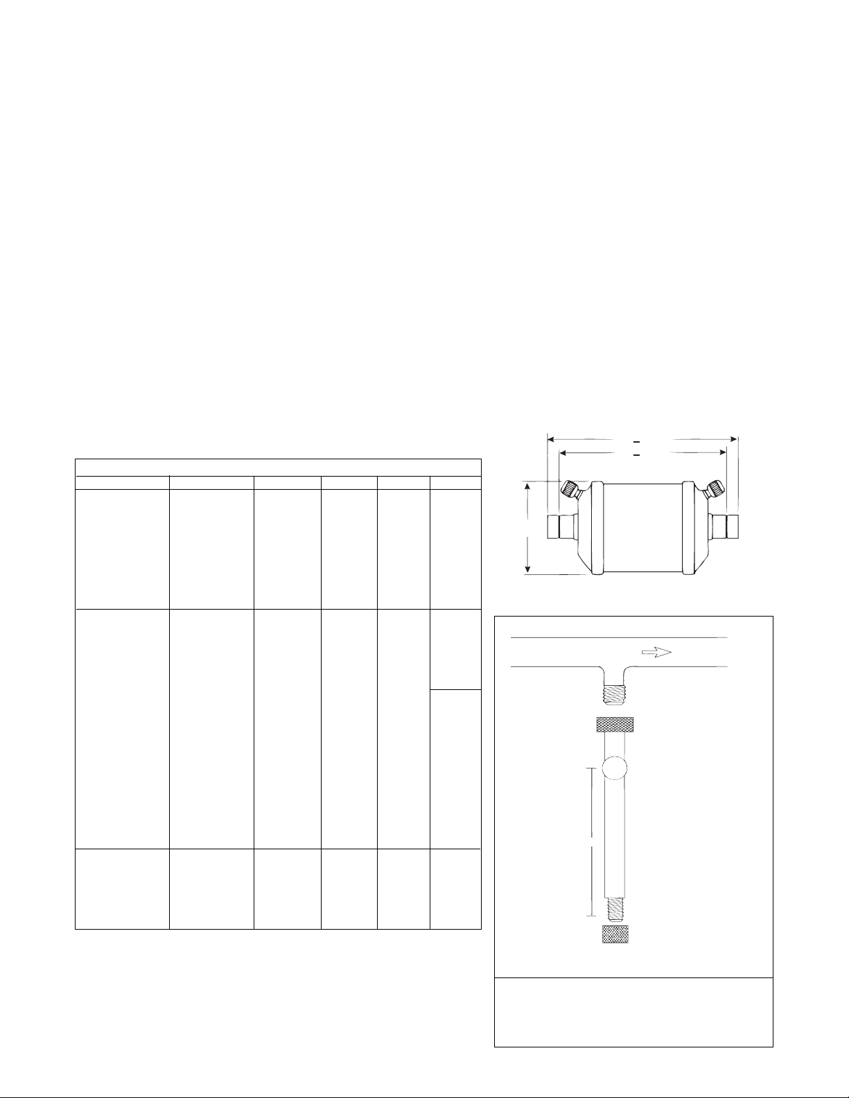
Refer to Table 1 for roughing-in dimensions.
7. Warning: Install with arrow pointing in direction of
flow (toward compressor). Reverse flow may
cause internal damage.
8. Clean and deburr piping ends to provide a good
brazing surface.
9. Use an inert gas, such as nitrogen, to pass thru the
lines while brazing to prevent formation of copper
oxides.
10. High temperature brazing alloys may be used.
Normal precautions should be taken by directing the
flame away from the filter-drier shell. Use chill blocks,
wet rags, or other suitable heat protection for the filterdrier.
11. When the shell has cooled, install valve cores with
tool provided and replace seal caps. Do not charge
system until valve cores are installed.
12. To prevent twisting the refrigerant line, use a back-up
wrench on the flats supplied on SAE connections.
13. Warning: Thoroughly leak-test the system after
installation. Failure to do so could result in loss of
refrigerant.
14. The products listed on this sheet should not be used
for liquid line or hot gas applications.
www.emersonflowcontrols.com
11911 Adie Road P.O. Box 411400 St. Louis MO 63141 USA CUSTOMER SERVICE (314) 569-4666
Page 2
Compressor Motor Burnout Clean-up Procedure – Suction Line Method
1. Determine the extent of the burnout. For mild burnouts,
where the contamination has not spread throughout the
system – it is economical to save the refrigerant charge if
the system has service valves on the compressor. A
severe burnout exists if the oil is discolored, and acid
odor is present, and contamination products are found on
the high and low side. In severe burnouts, extreme
caution should be exercised to avoid breathing the acid
vapors and to prevent contaminated liquid from making
contact with skin.
2. Thoroughly clean and replace all system controls, such
as: thermal expansion valves, solenoids, check valves,
reversing valves, etc. Remove all strainers and filterdriers.
3. Install a replacement compressor and make a complete
electrical check.
4. Make sure the suction line adjacent to the compressor is
clean. Install an Emerson suction line filter-drier.
5. Pressure and leak-test the system according to the unit
manufacturer’s recommendations.
6. Triple evacuate to at least 500 microns. Break the
vacuum with clean, dry nitrogen at 0 psig.
Table 1 — Rough-in Dimensions
Filter-Drier Type Filter Type Connection A B C
ASD 28S3-VV ASF 28S3-VV 3/8 ODF 4-23/32 5-19/32
ASD 28S4-VV ASF 28S4-VV 1/2 ODF 4-11/16 5-11/16
ASD 35F5-VV ASF 35F5-VV 5/8 SAE — 7-9/16
ASD 35S5-VV ASF 35S5-VV 5/8 ODF 5-9/32 6-17/32
ASD 45S6-VV ASF 45S6-VV 3/4 ODF 6-1/2 7-3/4 3-11/16
ASD 45S7-VV ASF 45S7-VV 7/8 ODF 6-7/16 7-15/16
ASD 50S9-VV ASF 50S9-VV 1-1/8 ODF 7-1/32 8-27/32
ASD 75S11-VV ASF 75S11-VV 1-3/8 ODF 10-5/16 12-1/4
ASD 75S13-VV ASF 75S13-VV 1-5/8 ODF 9-29/32 12-5/32
SFD 08F3-VV 3/8 SAE — 5-1/2
SFD 08S3-VV 3/8 ODF 5-5/16 6-3/16
SFD 08F4-VV 1/2 SAE — 5-3/4
SFD 08S4-VV 1/2 ODF 3-15/16 5
SFD 08S5-VV 5/8 ODF 3-29/32 5-5/32
SFD 08S6-VV 3/4 ODF 4-5/16 5-9/16
SFD 13F3-VV 3/8 SAE — 5-1/2
SFD 13S3-VV 3/8 ODF 3-31/32 4-27/32
SFD 13F4-VV 1/2 SAE — 5-3/4
SFD 13S4-VV 1/2 ODF 3-15/16 4-15/16
SFD 13F5-VV 5/8 SAE — 6-1/8
SFD 13S5-VV 5/8 ODF 3-29/32 5-5/32
SFD 13S6-VV 3/4 ODF 4 5-1/4
SFD 13S7-VV 7/8 ODF 4-1/4 5-3/4
SFD 27S7-VV 7/8 ODF 6 7-1/2
SFD 27S9-VV 1-1/8 ODF 5-13/16 7-5/8
SFD 54S11-VV 1-3/8 ODF 10-5/16 12-1/4
SFD 54S13-VV 1-5/8 ODF 9-29/32 12-5/32
A-TS/ASK-165S-VV
A-TS/ASK-166S-VV
A-TS/ASK-167S-VV
A-TS/ASK-306S-VV
A-TS/ASK-307S-VV
A-TS/ASK-309S-VV
5/8 ODF 5-3/16 6-7/16
3/4 ODF 5-5/16 6-3/4
7/8 ODF 5-1/2 7
3/4 ODF 8-7/16 9-11/16
7/8 ODF 8-3/8 9-7/8
1-1/8 ODF 8-7/16 10-1/4
7. Charge the system through an Emerson liquid line filter-
8. Start the compressor and put the system in operation.
9. Replace the suction line filter-drier if the pressure drop
10. Observe the system during the first 4 hours. Repeat step
11. After the system has been in operation for 48 hours,
12. Check the system again after approximately 2 weeks of
13. Clean-up is complete when the oil is clean and odor-free,
For detailed burnout clean-up procedure and recommendations, consult the
3-1/8
3-11/16
3-3/16
drier to equipment manufacturer’s recommendations.
Record the pressure drop across the suction line filterdrier on the enclosed label and apply to the side of the
drier shell.
becomes excessive.
9 as often as required, until no further change in pressure drop is observed.
check the condition of the oil with the Emerson Acid Alert
test kit. IF the oil test indicates an acid condtion, replace
both the liquid and suction line filter-drier. See fig. 1.
operation. IF the oil is still discolored, replace the liquid
and suction line filter-drier.
and is determined to be acceptable with the Emerson
Acid Alert test kit.
RSES Service Manual, section 91.
+
B .078
+
A .062
C*
*DOES NOT INCLUDE WELD BEAD
HORIZONTAL SUCTION LINE
TO COMPRESSOR
MALE SCHRADER FITTING
MUST BE ON BOTTOM OF LINE
FEMALE SCHRADER FITTING
3/8” SIGHT GLASS
3/8” TUBE
4” MINIMUM
SCHRADER FITTING & CAP
Figure 1
The piping arrangement shown will allow you
to remove an oil sample from a system with
a hermetic compressor, without having to
remove the charge.
 Loading...