

Page 1
Advantage® Actuator
Installation, Operation
and Maintenance Manual
IOM.AA.ASCO.en-US.2008-08
Designed and Manufactured by ITT
Page 2

Page 3

Table Of Contents
Introduction and Safety...................................................................................................................................................2
Safety
message levels.........................................................................................................................................................2
Warning...............................................................................................................................................................................2
Safety...................................................................................................................................................................................2
Product Description..........................................................................................................................................................4
Advantage actuator model number................................................................................................................................4
Identification tag............................................................................................................................................................4
Non-sealed and sealed bonnet description....................................................................................................................4
Valve diaphragm identification........................................................................................................................................5
Transportation and Storage............................................................................................................................................6
Transport and store the product.....................................................................................................................................6
Installation...........................................................................................................................................................................7
Install the valve and Advantage actuator.......................................................................................................................7
Install diaphragm...............................................................................................................................................................7
Mount the Advantage actuator to the valve................................................................................................................10
Tighten the bonnet fasteners.........................................................................................................................................10
Fastener torque table for valve body to actuator....................................................................................................10
Actuator operating pressure..........................................................................................................................................11
Set the adjustable opening stop.....................................................................................................................................11
Set the adjustable opening stop.....................................................................................................................................11
Set the manual over-ride (close)....................................................................................................................................11
Set the manual over-ride (open)....................................................................................................................................12
Table Of Contents
Advantage® Actuator Installation and Operation
Designed and Manufactured by ITT
Manual 1
Page 4
Introduction and Safety
Introduction and Safety
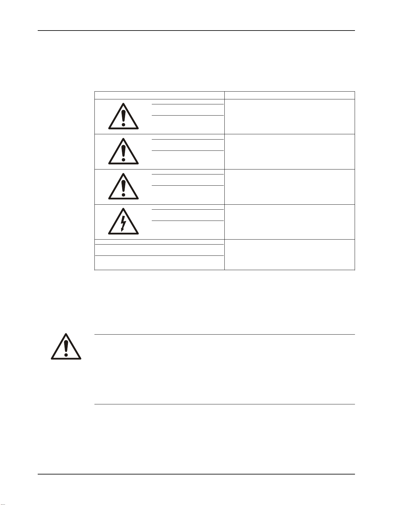
Safety message levels
Definitions
Safety message level Indication
DANGER:
WARNING:
CAUTION:
A hazardous situation which, if not avoided, will
result in death or serious injury
A hazardous situation which, if not avoided,
could result in death or serious injury
A hazardous situation which, if not avoided,
could result in minor or moderate injury
NOTICE:
User health and safety
General precautions
This product is designed and manufactured using good workmanship and materials, and meets
all applicable industry standards. This product should be used only as recommended by ITT or
ASCO.
WARNING:
• Misapplication of the valve can result in injury or property damage. Select valves and valve
components of the proper materials and make sure that they are consistent with your
specific performance requirements. Incorrect application of this product includes but is not
limited to:
• Exceeding the pressure or temperature rating
• Failing to maintain this product according to the recommendations
• Using this product to contain or control media that is incompatible with the materials of
construction
Electrical Hazard:
The possibility of electrical risks if instructions
are not followed in a proper manner
• A potential situation which, if not avoided,
could result in an undesirable result or
state
• A practice not related to personal injury
Qualifications and training
The personnel responsible for the assembly, operation, inspection, and maintenance of the
valve must be appropriately qualified. The operating company must do the following tasks:
• Define the responsibilities and competency of all personnel handling this equipment.
• Provide instruction and training.
Advantage Actuator Installation and Operation Manual2
Designed and Manufactured by ITT
Page 5

• Ensure that the contents of the operating instructions have been fully understood by the
personnel.
Instruction and training can be carried out by ASCO as the reseller of the valve by order of the
manufacturer.
Non-compliance risks
Failure to comply with all safety precautions can result in the following conditions:
• Death or serious injury due to electrical, mechanical, and chemical influences
• Environmental damage due to the leakage of dangerous materials
• Product damage
• Property damage
• Loss of all claims for damages
Operational safety precautions
Be aware of these safety precautions when operating this product:
• Do not leave hot or cold components of the product unsecured against contact if they are a
source of danger.
• Do not remove the contact guard for moving parts when the product is in operation. Never
operate the product without the contact guard installed.
• Do not hang items from the product. Any accessories must be firmly or permanently
attached.
• Do not use the product as a step or hand hold.
• Do not paint over the identification tag, warnings, notices, or other identification marks
associated with the product.
Introduction and Safety
Maintenance safety precautions
Be aware of these safety precautions when performing maintenance on this product:
• You must decontaminate the product if it has been exposed to harmful substances such as
caustic chemicals.
Use of unauthorized parts
Reconstruction or modification of the product is only permissible after consultation with ITT.
Genuine spare parts and accessories authorized by ITT serve to maintain safety. Use of nongenuine ITT parts can annul liability of the manufacturer for the consequences. ITT parts are
not to be used in conjunction with products not supplied by ITT as this improper use can annul
all liability for the consequences.
Unacceptable modes of operation
The operational reliability of this product is only guaranteed when it is used as designated. The
operating limits given on the identification tag and in the data sheet may not be exceeded under
any circumstances. If the identification tag is missing or worn, contact ASCO for specific
instructions.
Advantage Actuator Installation and Operation Manual 3
Designed and Manufactured by ITT
Page 6

Product Description
Product Description
Advantage actuator model number
The Adv
located on the ITT identification tag. The model number is a four digit number defining the actuator as
follows:
A = Advantage Actuator
Mode of Operation
Actuator Series Size
Values in parentheses are specific spring combinations for fail close actuators.
Series size 3, 5, 8, etc. equates to diaphragm effective area.
Examples:
Model # A308 = double acting actuator series 8
Model # A232 = fail close actuator series 33 with a 32 spring set
antage actuator is a spring or double acting pneumatic actuator. The actuator model number is
• 1 = Fail Open (spring to open, air to close) (Direct Acting)
• 2 = Fail Close (spring to close, air to open) (Reverse Acting)
• 3 = Double Acting (air to open, air to close)
• 3 (03, 04)
• 5 (05, 06)
• 8 (08, 09)
• 16 (15, 16, 17)
• 33 (32, 33, 34, 35)
• 47 (47, 48)
Identification tag
Line 1 — V
Line 2 — Valve size and model number
Line 3 — Valve diaphragm type
Line 4 — Maximum recommended actuation pressure
alve serial number
Non-sealed and sealed bonnet description
The non-sealed bonnet has a weep hole that permits leakage of the process fluid if the diaphragm
ruptures. The sealed bonnet uses a special “v-notch” vent plug, which permits inspection for diaphragm
rupture.
4 Advantage® Actuator Installation and Operation
Designed and Manufactured by ITT
Manual
Page 7

Figure 1: V-notch vent plug
Valve diaphragm identification
Diaphragm tab codes
All diaphragm materials and physical properties are batch traceable via permanent codes molded into the
diaphragm tabs. The molding date, grade of diaphragm, and valve size provide traceability to original batch
records.
Product Description (Continued)
Date Code
Valve Size
Supplier Code
Grade of
Diaphragm
Advantage® Actuator Installation and Operation
Designed and Manufactured by ITT
Manual 5
Page 8

Transportation and Storage
Transportation and Storage
Handling and unpacking guidelines
CAUTION:
Always observe the applicable standards and regulations regarding the prevention of
accidents when handling the product.
Handling guidelines
Follow these guidelines when handling the product to prevent damage:
• Use care when handling the product.
• Leave protective caps and covers on the product until installation.
Unpacking guidelines
Follow these guidelines when unpacking the product:
1. Inspect the package for damaged or missing items upon delivery.
2. Note any damaged or missing items on the receipt and freight bill.
3. Do not lift or pull on the electrical conduit lines. Doing so may cause the POC switches to
come out of calibration.
Storage, disposal, and return requirements
Storage
If you are not immediately installing the product after delivery, store it as follows:
• Store the product in a dry room that maintains a constant temperature.
• Make sure that the products are not stacked on top of one another.
Disposal
Dispose of this product and associated components in compliance with federal, state, and local
regulations.
Return
Ensure these requirements are met before you return a product to ASCO:
• Contact ASCO for specific instructions on how to return the product.
• Clean the valve of all hazardous material.
• Complete a Material Safety Data Sheet or Process Data Sheet for any process fluid that
could remain on the valve.
• Obtain a Return Material Authorization from the factory.
Advantage Actuator Installation and Operation Manual6
Designed and Manufactured by ITT
Page 9

Installation
Install the valve and Advantage actuator
Installation
Note: T
Consult the engineering catalog for actuator sizing. Consult the factory or engineering
catalog for vacuum operation.
Consider the following information before installing the actuator:
•
The series 3, 5, 8, or 16 stainless steel bonnet Advantage Actuator can have the air inlets positioned in
any quadrant.
• Maximum valve operating pressure is 150 PSIG (10.34 bar). This pressure is applicable up to 100º F
(38º C). Valves at maximum pressure cannot be used at maximum temperatures.
To install the valve and Advantage Actuator, complete the following procedure:
1. If welding manually, remove the actuator.
2. If welding end valves for schedule 10 or heavier pipe, remove the actuator prior to welding in line.
3. If welding end valves for schedule 5 or lighter pipe and tubing, welding with automatic equipment is
acceptable. In this situation, complete the following steps prior to performing the weld.
a) Do not remove the actuator.
b) Set the valve to the open position.
c) Properly purge the valve with an inert gas.
4. Install the valve stem between 0 and 30 degrees above horizontal for horizontal piping systems to be
drained through the valve.
The proper valve orientation differs depending upon the valve type.
• Dia-Flo diaphragm valves can be installed in any orientation.
• Pure-Flo valves have either raised hash marks (castings) or small machined dots (forgings) on the
valve body to indicate the correct drain angle. Position these marks at the 12 o’clock position to
achieve the optimum drain angle.
5. Prior to pressurization (with the valve slightly open), follow the steps in the Tighten the bonnet
fasteners.
6. For series 33 and 47 actuators, prepare an eye bolt with a 0.625" -18 female thread to attach to the
adjusting bushing.
he actuator size and configuration can limit the actual operating pressure.
Note: Do not lift series
Note: If the actuator
7. Connect the air line.
Connection size is 1/8" NPT
actuators.
Note: Air line connections should be made with
plastic actuator covers.
8. Cycle the valve two to three times to verify smooth operation.
Install diaphragm
1.
Unscrew the diaphragm from the compressor by turning counterclockwise.
a) Periodically inspect the valve compressor pin for excessive wear. Replace the pin or compressor if
excessive wear or axial pin movement is found.
The replacement diaphragm should be identical in size and grade to the original diaphragm.
2. For PTFE assemblies only:
Advantage® Actuator Installation and Operation
Designed and Manufactured by ITT
33 and 47 actuators by their air fittings.
is a series 47 actuator, use a hoist to lift the valve.
for series 3, 5, 8 and 16 actuators and 1/4" NPT for series 33 and 47
care so as not to damage the
Manual 7
Page 10

Installation (Continued)
a) Install the new elastomer backing cushion over the tube nut.
b) Invert the PTFE diaphragm by pressing the center of the diaphragm face with your thumbs while
holding the edge of the diaphragm with your fingers.
c) Engage the threads of the diaphragm into the tube nut by rotating clockwise.
d) Continue rotating the PTFE diaphragm clockwise into the compressor while securing the backing
cushion from rotating
.
3. Rotate the diaphragm until hard stop or heavy resistance is achieved and additional force does not
significantly
8 Advantage® Actuator Installation and Operation
rotate the diaphragm into the compressor.
Designed and Manufactured by ITT
Manual
Page 11

4. For PTFE assemblies only reinvert diaphragm.
Installation (Continued)
5. Back off (no more than 1/2 turn) until the bolt holes in diaphragm and the bonnet flange align.
Advantage® Actuator Installation and Operation
Designed and Manufactured by ITT
Manual 9
Page 12

Installation (Continued)
Mount the Advantage actuator to the valve
Regulate air pressure
1.
Options
If the actuator mode of
operation is ...
1 or 3 regulate the air pressure in the upper cover to extend the
2 regulate the air pressure in the lower cover to properly position
2. Follow steps in Install diaphra
3. Assemble the valve body following the steps in Tighten the bonnet fasteners.
4. Travel stop, if equipped, must be reset at this time to ensure proper closure. Follow steps in Adjust
the travel (closing) stop.
Tighten the bonnet fasteners
Caution: Do not tighten fasteners
temperatures (> 100°F/ 38°C).
1. Depressurize the system.
2. Use regulated air pressure to position diaphragm so that valve is slightly open. It may be necessary to
use air pressure to actuate the valve.
3. Tighten the bonnet fasteners in a crisscross pattern in accordance with the Fastener torque table for
valve body to actuator.
4. Make multiple criss-cross passes to build up torque to the final table value. Make additional criss-cross
passes using final table values to evenly tighten each fastener to within 5% of torque value.
5. Retighten the bonnet fasteners as noted above at ambient conditions after the system has cycled
through operating pressure and temperature.
6. Monitor the valve for leakage.
Description
then ...
compressor
the v
gm.
.
alve diaphragm.
while the system is pressurized or at elevated
If ... then ...
leakage occurs at the body/bonnet
flange sealing area
leakage continues follow the steps in Replace valve diaphragm.
depressurize the system and retighten the bonnet
fasteners as noted above.
Fastener torque table for valve body to actuator
Valve Size Bolt Size PTFE Diaphragm Elastomer Diaphragm
Inch DN Imperial Metric in-lb N-m in-lb N-m
Bio-Tek
3/8,
(1/4,
1/2")
1/2" 15 1/4" M6 25-60 2.8-6.8 20-40 2.3-4.5
3/4" 20 1/4" M6 50-65 5.7-9.1 20-50 2.3-5.7
1" 25 5/16" M8 65-90 7.4-11.3 45-70 5.1-7.9
10 Advantage® Actuator Installation and Operation
Bio-Tek
(8, 10,
#6 M4 20-25 2.3-2.8 20-25 2.3-2.8
15)
Designed and Manufactured by ITT
Manual
Page 13

Valve Size Bolt Size PTFE Diaphragm Elastomer Diaphragm
Inch DN Imperial Metric in-lb N-m in-lb N-m
1 1/2" 40 3/8" M10 200-225 23-25 75-130 8.5-14.7
2" 50 7/16" M12 225-275 25-31 100-180 11-20
3" 80 5/8" M16 750-1000 85-113 300-420 34-48
4" 100 1/2" M12 540-600 61-83 190-230 22-26
Values given are for lubricated fasteners.
Minim
um values given will provide longer diaphragm cycle life for valves in non-autoclave and low
thermal cycle conditions.
Maximum values given may be necessary for autoclave conditions and for high thermal cycle conditions.
Torques should be applied at near ambient conditions (< 100ºF/ 38ºC).
Actuator operating pressure
Maximum permitted air supply pressure is 90 psig (6.2 bar, 620 kPa).
The actuator has a pressure rating of 90 psig. However, the actuator will withstand pressures well in excess
of the rated pressure without risk of bursting. Maintaining operating pressure at or below 90 psig will
ensure optimum life of the operating components, such as the actuator diaphragm. However, operation at
pressures up to 100 psig (6.9 bar), for limited periods of time, will not noticeably affect the life of these
components.
Installation (Continued)
Set the adjustable opening stop
These instructions are for series 3, 5, 8, 16 actuators.
1. Remove the switch package, if present.
2. Using air pressure and a bleed type regulator, open the valve to the desired position.
3. Rotate the adjusting bushing counterclockwise until resistance is felt. The opening stop is now set.
4. Adjust the valve closed switch.
Set the adjustable opening stop
These instructions are for series 47 actuators.
1. Remove the switch package, if present.
2. Remove the clear plastic cap.
3. Using air pressure and a bleed type regulator, open the valve to desired position.
4. Rotate the adjusting bushing counterclockwise until resistance is felt. Count and record the number of
turns.
5. Loosen the two jam nuts and turn the lower nut clockwise the same number of turns as recorded above.
6. Lock the nuts together.
7. Adjust the travel stop. Follow steps in Adjust the travel (closing) stop.
8. Replace the clear plastic cap.
Set the manual over-ride (close)
For series 47 actuator, fail open and double acting only. Wrench closing not available on series 3, 5, 8, 16,
or 33.
1. Remove the switch package, if present.
Advantage® Actuator Installation and Operation
Designed and Manufactured by ITT
Manual 11
Page 14

Installation (Continued)
2. Release any air pressure in the bottom cover.
3.
Remove the clear plastic cap.
4. Use a wrench to turn the adjusting bushing counter clockwise to close the valve. Count and record the
number of turns.
5. Turn the adjusting bushing clockwise the recorded number of turns to return the valve to the open
position.
6. Tighten the travel stop nuts and assemble the clear plastic cap.
Set the manual over-ride (open)
This procedure is for series 47 actuators only.
1. Remove the switch package, if present.
2. Release any air pressure in the top cover.
3. Remove the clear plastic cap and loosen the jam nuts.
4. Use a wrench to hold the adjusting bushing from rotating and turn the lowest jam nut clockwise. This
opens the valve 0.056" (1.42 mm) per rotation.
5. Rotate the nut counterclockwise to return the valve to the closed position.
6. Adjust the travel stop. Follow steps in Adjust the travel (closing) stop.
7. Tighten the jam nuts together and assemble the clear plastic cap.
12 Advantage® Actuator Installation and Operation
Designed and Manufactured by ITT
Manual
Page 15

Page 16

Visit our website for the latest version of this
document and more information:
www.emerson.com
United Kingdom
Customer Service Sales Admin 44-(0)1695-71 36 14
enquiries.asco.uk@emerson.com
France:
Sales Admin: 02 37 24 47 76
anf .serviced ients@emerson.com
Italy
+39 02 95037010
ANS .AFTERSALES@Emerson.com
Netherlands
+31332777805
info.a sco.nl@emerson.com
Spain
+34 942 876 101
ventas.ane@emerson.com
Germany:
Tel. +49 7237 996 100
AND.Sales@emerson.com
ASCO'"
© 2019 ITT Corporation
The original instruction is in English. All non-English instructions are translations of the original
instruction.
Designed and Manufactured by ITT
IOM.AA.ASCO.en-US.2008-08
 Loading...