

Page 1
Page 2
Maximum reliability and excellent value
ASCO 920 Remote Control (RC) Switches
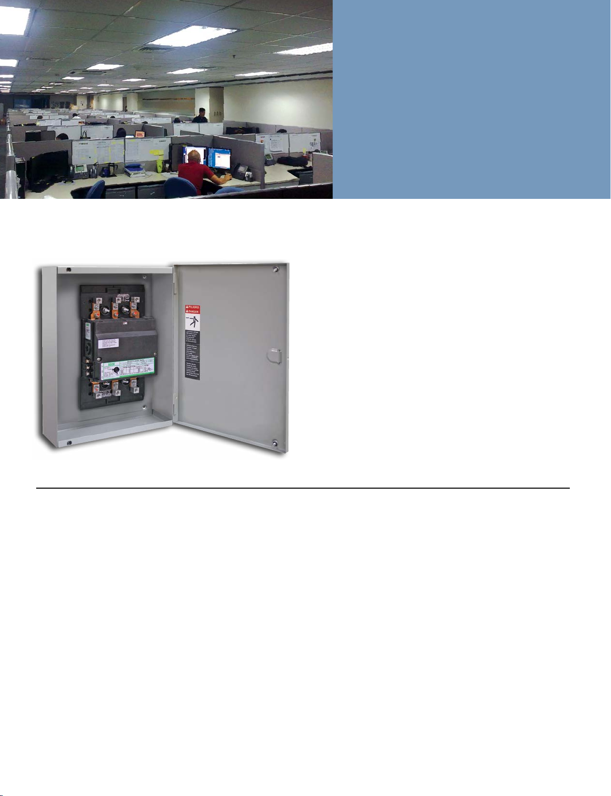
ASCO 920 Remote Control Switch
in Type 1 Enclosure
ASCO 920 Features
Electrical Features
•UL listed. CSA Approved
•Meets UL 67 requirements
with short-circuit rating
(Withstand Current Rating)
of 22,000 Amps rms symmetrical at 480 volts for use
with molded case circuit
breakers; 100,000 Amps
rms symmetrical at 600
volts for use with currentlimiting fuses.
•Interrupts 300% of rated
current at 480 volts, 0.4 to
0.5 power factor
•Can be used with metal halide, mercury vapor, quartz
halogen, tungsten and
uorescent lighting.
•No derating when used on
high inrush loads such as
cold tungsten lamps.
•Wide arc gaps and arc splitters to quickly extinguish
arcs. Isolated arcing chambers are widely spaced and
symmetrically located.
The ASCO 920 is designed
as a feeder disconnect switch
for load capacities beyond
the ASCO 917. ASCO 920
RC switches are available for
separate mounting in NEMA
type enclosures or direct
mounting within lighting
panelboards for total or splitbus applications.
It is available from 30
through 225 Amperes per
pole with 2 or 3 poles and
service voltages through 600
volts AC. The ASCO 920 is
listed under UL 508 for ballast
lighting, tungsten, general
use and resistive loads. It also
Construction Features
•Long life. Designed for
more demanding lighting
contactor use. Provides
extended life and quieter
operation.
•Suitable for use with energy
management systems.
•Rugged molded base and
cover with superior electrical insulation.
•Provisions for manual
operation during inspection
and maintenance.
•Lightweight for easy
installation.
•Plug-in auxiliary control
relays available.
meets the withstand current
requirements of UL 67 for
panelboard applications.
The ASCO 920 is easy to
install and features all position mounting, no derating
for high inrush loads and
a reliable single-solenoid
operator. ASCO 920 RC
switches can be used with
energy management systems
which automatically control
lighting and power circuits
through control devices
such as photoelectric cells,
microprocessors, timers and
occupancy sensors.
•Control line terminal
clamps simplify installation:
Insert wire and tighten.
Wire range #14 AWG to
#10 AWG.
•Contacts are power-driven
in both directions for
complete dependability.
•No extra wires or contacts
needed to install signal
lamps at control stations.
•Can be mounted in any
position.
•Available from stock from
30-225 Amps.
Page 3

The largest service
organization of its kind
ASCO 920 Optional Auxiliary Control Relays
Features
•Allows control of RC
switches directly from
energy management
systems.
•UL recognized for use with
ASCO RC switches.
•Permits low voltage AC or
•Polycarbonate dust cover
for protection against
industrial environment.
•Barrier screw type terminals
with approved means for
solderless connection of
conductors.
DC normal.
•Low VA burden.
•Narrow width design.
•Incorporates ASCO 115
relays.
Two-Wire Control Accessory 47
Catalog No. 321A40
ASCO relay for two-wire control.
Standard Control Voltages:
24,120, 208, 240, 277VAC,
50 or 60Hz, 24 or 110VDC
Three-Wire Control Accessory 48
Catalog No. 321A36
ASCO relay for three-wire control.
Standard Control Voltages:
24,120, 208, 240, 277VAC,
50 or 60Hz, 12, 24, 32, 48
or 110VDC
Auxiliary Control Relays to Operate
RC Switches are useful when:
• When the controlling device does not
have adequate current-carrying capacity
to directly control the RC switch.
• When the control station is to be located at a
distance greater than the allowable RC switch
line run.
• When the controlling device is only available
as a single pole, single throw contact,
necessitating a two-wire control line.
• When Form 3 (start-stop) control for an RC
switch is required.
Two-wire
relay control
of a remote
control switch
Accessory 47
Three-wire
relay control
of a remote
control switch
Accessory 48
Dimensions inches (mm) for ASCO
two-wire and three-wire Control Relays
Height
6-1/2”
165 (mm)
1. Dimensional data is approximate and subject to change.
Certified dimensions available upon request.
Width
2”
51 (mm)
Depth
3-3/8”
86 (mm)
1
Rating
Nominal AC
Pickup Voltage AC
Nominal DC
Pickup Voltage DC
Maximum Voltage
Accessory 47
3.0 VA
85% of Nominal
2.5 Watts
80% of Nominal
120% of Nominal
Accessory 48
2.0 VA
85% of Nominal
1.2 Watts
75% of Nominal
120% of Nominal
Operating Coil Characteristics
Page 4

ASCO is the global leader in
power switching and controls
ASCO 920 Product Specifications
Switch Only (Panelboard Mounting)
Switch Rating
Amps
30-100
150-225
Dimensions, In. (mm)
Width
7-15/16 (201)
7-15/16 (201)
Height
8-5/16 (211)
9-1/2 (241)
Switch With Sub-Panel (Panelboard Mounting)
Switch
Rating Amps
30-100
150-225
4. Enclosure gutter spaces are based on non-looping of cables within the enclosure. Where cables must be looped
within the enclosure, oversize cabinets are available at extra cost. Contac t ASCO for complete information.
Dimensions, In. (mm)
Width
7-15/16 (201)
7-15/16 (201)
Height
11-3/4(298)
14-1/2(368)
Maximum Voltage Ratings at Rated Amps, Open or Enclosed
When Connected
1 Pole to Load
Ballast
Tungsten
General Use
277 VAC
250 VAC
347 VAC
When Connected 2 Poles to Load on 1
and 3 Poles to Load on 3
Ballast
Tungsten
General Use
1,2,3
Depth
3-1/2 (89)
3-1/2 (89)
Depth
3-7/8 (98)
3-15/16(100)
Approx. Shipping
Weight Lb. (kg)
6 (2.7)
7(3.2)
4
Approx. Shipping
Weight Lb. (kg)
8(3.6)
11(5.0)
480 VAC
250 VAC
600 VAC
1. Suitable insulation must be behind switch unit.
2. Suitable for bus bar mounting. Lugs not supplied.
3. Dimensional data is approximate and subject to change.
Certified dimensions available upon request.
NEMA Type 1
Enclosure Dimensions, In. (mm)
Width
13(330)
13(330)
5
5. For DC service, maximum current rating is 75 amps or switch rating,
whichever is less, with maximum voltage rating of 125 volts
when connected 1 pole to load and 250 volts when
connected 2 poles to load.
Height
18-1/4(464)
24(610)
Depth
4-1/2 (114)
4-1/2 (114)
Inrush Current Values and Minimum
Recommended Control Circuit Fuse Size
Switch
Rating Amps
30-100
150-225
6. Overcurrent protective device ratings for control circuits should be selected and installed in accordance with the NEC.
7. This table shows the minimum permissible control circuit fuse size, based on the operating coil’s momentary inrush current.
8. ASCO furnished control fuses are rated at 15 Amps.
120 Volts, 60 Hz
Inrush
Minimum
Amps
24
30
Fuse
8
10
Wire Size for Service and
Control Connections
Switch Rating
Amps
AWG-MCM
30
60-75
100
150-200
225
9. Control circuit connections are supplied with terminals
accommodate a copper wire range of #14 AWG to #10 AWG.
10. Service connection for switches on sub-panels are
furnished with solderless lugs to accommodate copper or
aluminum wire, except on 30 Amp size which is provided
with 1/4” studs.
9,10
AL or CU
Terminal Lug
Wire Range
14-8
12-2
14-1/0
6-250
4-400
No. of Cable
per Terminal
Lug Connector
1
1
1
1
1
6,7,8
240 Volts, 60 Hz
Inrush
Amps
12
15
Maximum Distance Between Control Station and One ASCO
920 RC Switch with Source Line Voltage at 90% of Normal
Switch Rating
11. If the control device does not have adequate current-carrying capacity to control the
switch directly, or the control station is to be located a greater distance from the
switch than is allowed in the above table, auxiliar y control relays for 2-wire, or 3-wire
control are available. See optional accessories on inside tab.
12. For 208 volt system, reduce 240 volt values by 15%.
13. For 265 volt system, reduce 277 volt values by 5%.
Minimum
Fuse
4
5
Amps
30-100
150-225
277 Volts, 60 Hz
Inrush
Amps
11
13
AWG
No.
14
12
10
14
12
10
Minimum
Fuse
4
5
Distance in Feet
120 Volts,
60Hz
465
740
1175
395
630
1000
Approx. Shipping
Weight Lb. (kg)
23(10.4)
31(14.0)
480 Volts, 60 Hz
Inrush
Amps
6
7
240 Volts,
60Hz
1860
2960
4700
1580
2520
4000
Minimum
Fuse
2
3
11
12,13
277 Volts,
60Hz
2480
3940
6265
2100
3350
5325
Page 5

Creative, responsive, customer - focused and competitive.
ASCO 920 Ordering Information
Continuous Ampere
AC/DC
30
60
75
Rating
1
AC
100
150
200
225
Product
Code
920
No.
of Poles
2
3
1. For DC service, maximum current rating is 75 Amps or switch rating, whichever is less, with maximum voltage rating of 125 volts when connec ted 1 pole to load and 250
volts when connected 2 poles to the load.
2. All at 50 or 60 Hz. For voltages other than those listed, and for DC applications, contact your nearest ASCO source.
3. Specied only when ASCO 920 is to be mounted within a panelboard. A sub -panel is required when mounting in NEMA type enclosures
Voltage Code
Voltage
110 to 120V
208 to 240V
265 to 277V
440 to 480V
Other
Voltages Up
to 480
2
Sub-Panel
Code
3
6
7
9
X
Sub Panel
1= Sub-Panel
0 = No
3
Options
Leave Blank
for No
Options.
“X” Indicates
Options. List
Separately.
See Below.
Enclosures
Leave Blank for
Open - Type.
“C” Indicates
NEMA Type1,
or
Specify Other
Type Required.
Example: The catalog number for an ASCO 920, 3-pole, 225-amp switch with a
control coil voltage of 277 volts, 60 Hz, with an Optional Accessory 48 and a sub-panel, in a
NEMA Type 1 enclosure is: 920322571XC with option 48A(120V)
Optional Accessories
ASCO 920 Remote Control Switch
Option Description
Auxiliary contacts, one normally open and one normally
closed. Supplied as a pair. Rated 10 amps at 480 VAC.
Fully-rated neutral plate
Auxiliary control relay for 2-wire control
Auxiliary control relay for 3-wire control
Auxiliary control relay for Form 3 control
Control line fuse:
For grounded control voltage (to 300V)
For ungrounded control voltage (to 300V)
For ungrounded control voltage (301 - 600V)
1. A maximum of one pair of optional 14A and 14B contacts can be supplied on the above indicated remote
control switches.
2. The Amperage of the neutral plate will be equal to the Amperage of the specied remote control switch.
Lugs capable of accommodating the same cables as a single main pole are provided.
3. When ordering specify desired control voltage. See nex t page for control voltages.
4. Control line fuses can be used to supply power from the remote control switch enclosures to external
control stations. Any incoming service or control power should have appropriate overcurrent protec tion
at their source as required by application codes. For a grounded control voltage, one fuse should be
ordered; for an ungrounded control voltage, two fuses should be ordered.
5. Shipped loose for open types. Installed for enclosed types.
6. U.L. recognized.
See Notes
1
2
3,5,6
3,5,6
3,5,6
4,5
Specify Option
14A and 14B
22
47
48
49
52A
52B
52C
with sub-panel
Page 6

Emerson Network Power - Global Headquarters
1050 Dearborn Drive
Columbus, OH 43085
Tel: +1 614 888 0246
ASCO Power Technologies - Global Headquarters
50 Hanover Road
Florham Park, NJ 07932
800-800-ASCO
www.EmersonNetworkPower.com/ASCO
Emerson. Consider it Solved., Emerson Network Power and the Emerson Network Power logo are trademarks and service marks of Emerson Electric Co. ©2013 Emerson Electric Co. All rights reserved.
Publication 3206 R3 © September, 2013 Printed in the U.S.A.
www.ascoapu.com
 Loading...