

Page 1

Series 7000 Frequently Asked Questions
Features
How do I access the event logs?
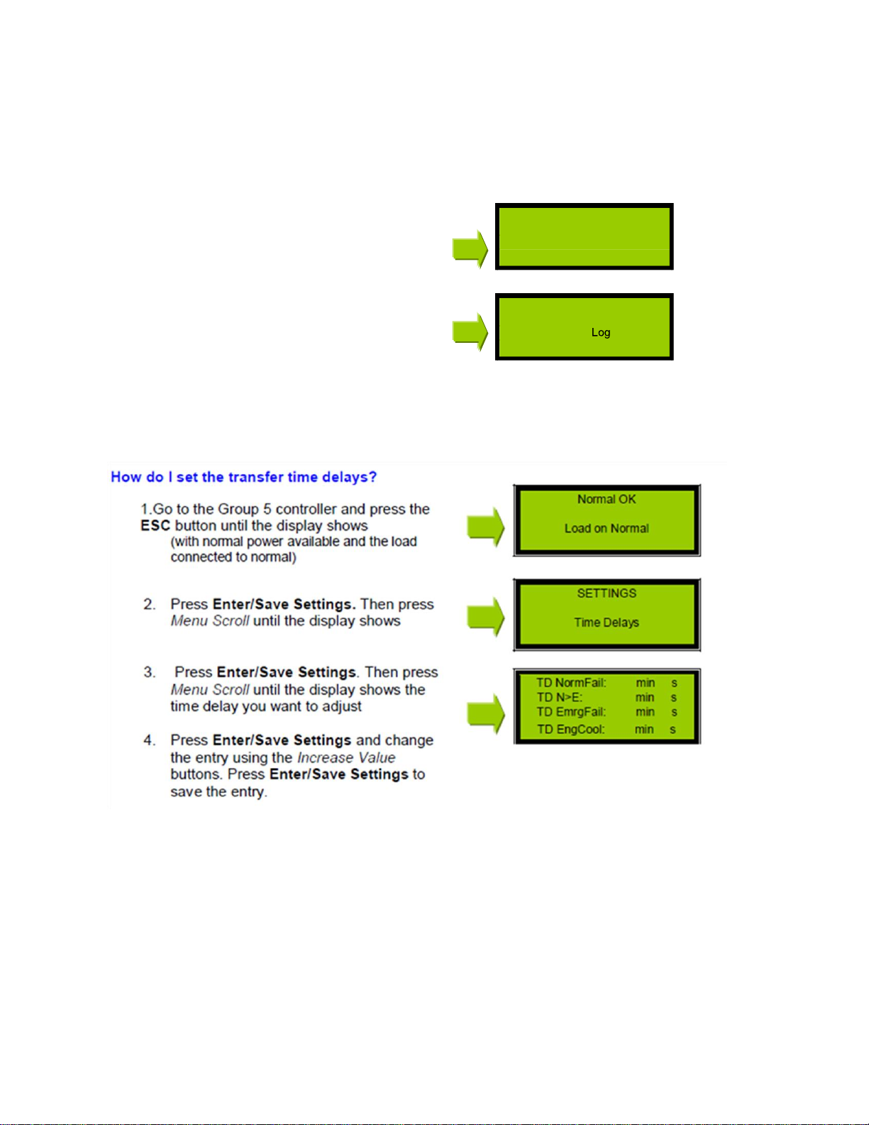
How do I set the transfer time delays?
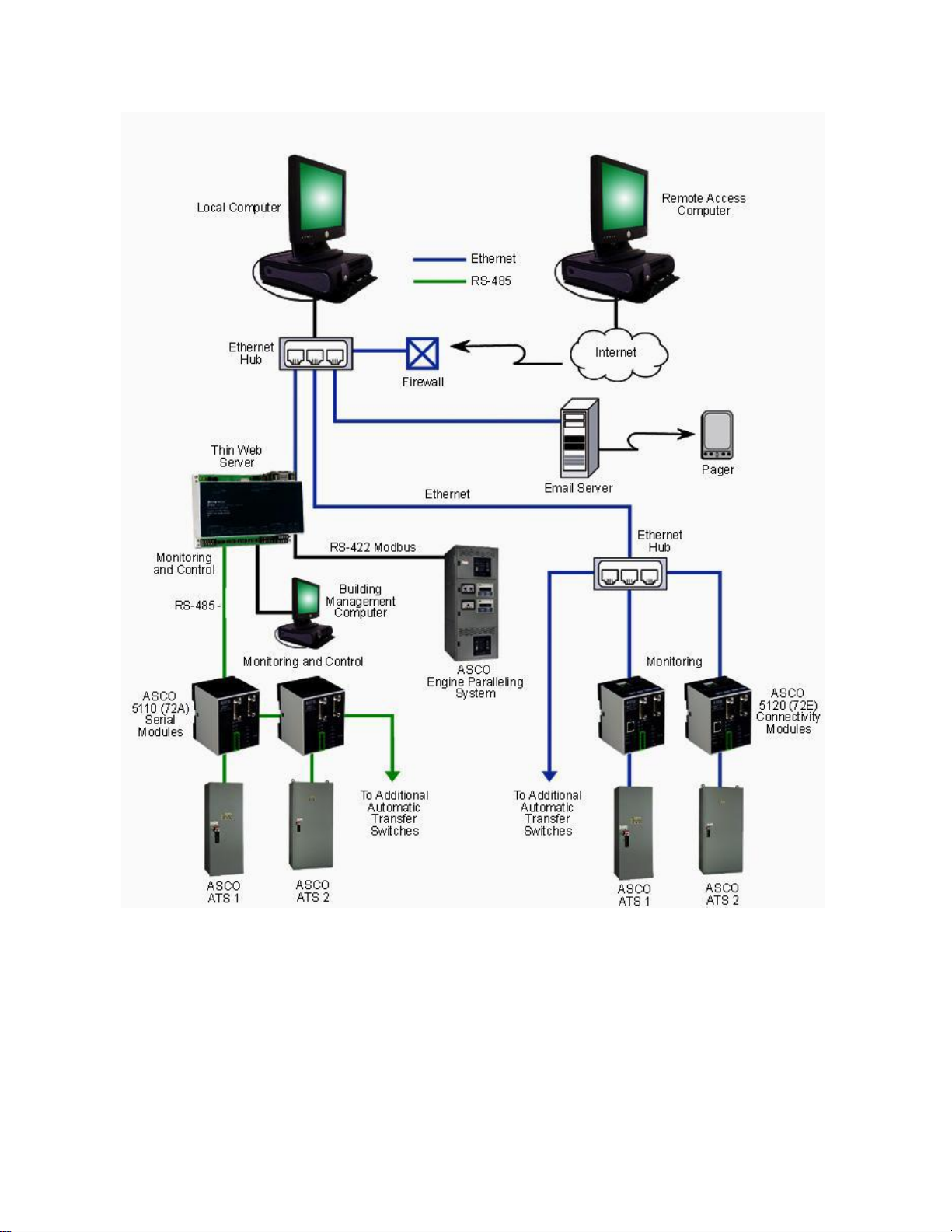
How do I communicate with the ATS?
How do I prevent or inhibit the ATS from transferring?
How do I set the engine exerciser?
Is the clock engine exerciser accurate? What
is an in-phase monitor?
How do I specify the ATS?
What auxiliary features does the ATS offer?
How does the engine exerciser work?
Where can I get load shed signals?
Where can I get pre-transfer and post-transfer signals?
Where can I get source availability signals?
Where can I get source availability signals?
Where can I get switch position contacts?
Where can I send remote transfer signals?
What is the default password?
Operation
Can I adjust the sensing of the controller?
How do I change the password?
How do I perform a transfer test?
How does the ATS work?
How does the engine exerciser work?
Is there a preferred source?
What is the operating temperature of the ATS?
Others
Literature Request
Parts Inquiry
Warranty Issues
Page 2

Product Installation
Can the ATS switch between different voltages?
How do I configure the ATS controller?
How do I install an ATS?
What is the maximum length of the control line?
Where can I get the weight and dimensions of the ATS?
What size cable or wire can I use for the power connections of the ATS?
When do I need to connect the neutral?
How do I specify the type of neutral?
What is the WCR of the ATS?
Which breakers are tested with an ASCO transfer switch?
Service
Can I modify the voltage rating of the ATS?
How can I extend the feature 1C timer?
How do I contact a service technician?
How do I convert an ACTS to an ATS? How
do I convert an ATS to an ADTS?
How do I convert the ATS from 1Φ to 3Φ?
How will I know if the controller is damaged?
What does this alarm message mean?
What should I do if the indicator lights are faulty?
Why won't the ATS retransfer to normal?
Why won't the ATS start the generator?
Why won't the ATS transfer to Emergency?
Why won't the engine exerciser work properly?
Why won't the generator shut-off?
Wiring
Where do I connect the engine start wires?
How can I re-wire my power manager connections?
Page 3
Normal OK
Load on Normal
<<< VIEW >>>
Event
Features
How do I access the event logs?
To access the event logs:
1. Go to the Group 5 controller and press the
ESC button until the display shows
2. Press Enter/Save Settings, then Menu
Scroll until the display shows
3. Press Enter/Save Settings, then Menu
Scroll to view the events.
Page 4
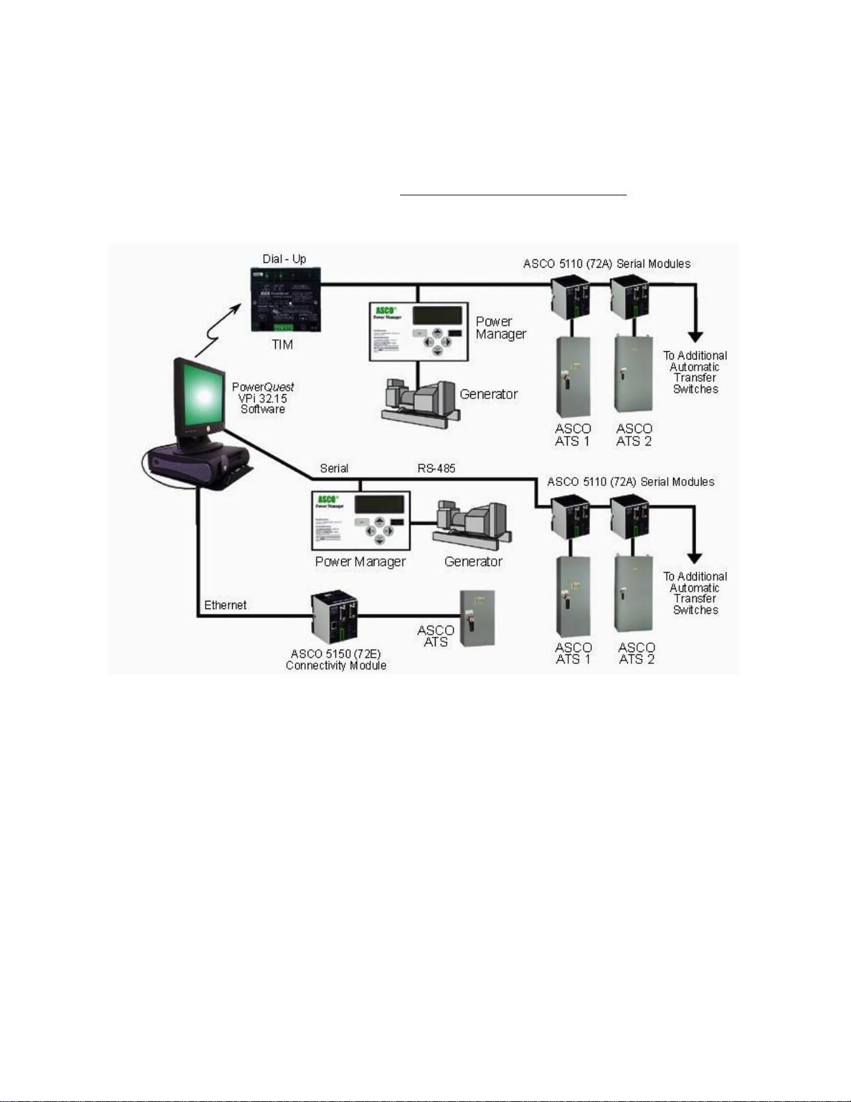
How do I communicate with the ATS?
To communicate with the Series 7000 group 5 controller you will need accessory 72E communication
module. With this you can access the group 5 controller to communicate through MODBUS RTU,
MODBUS TCP protocols at 9600 and 19.2K-baud rates. For a detailed discussion regarding
Communication products and application, go to Communications Product s F AQ ’s.
Page 5
How do I configure the inhibit transfer signal?
Inhibit features are included in the Factory Selectable Features program of the Group 5 controller,
therefore it cannot be modified by the end user. These optional accessories are usually specified by the
customer to be included in the ATS’s upon ordering. If requested for ATS Site, contact ASCO Services
by Dialing 1-800-800-ASCO to arrange a service call.
Page 6
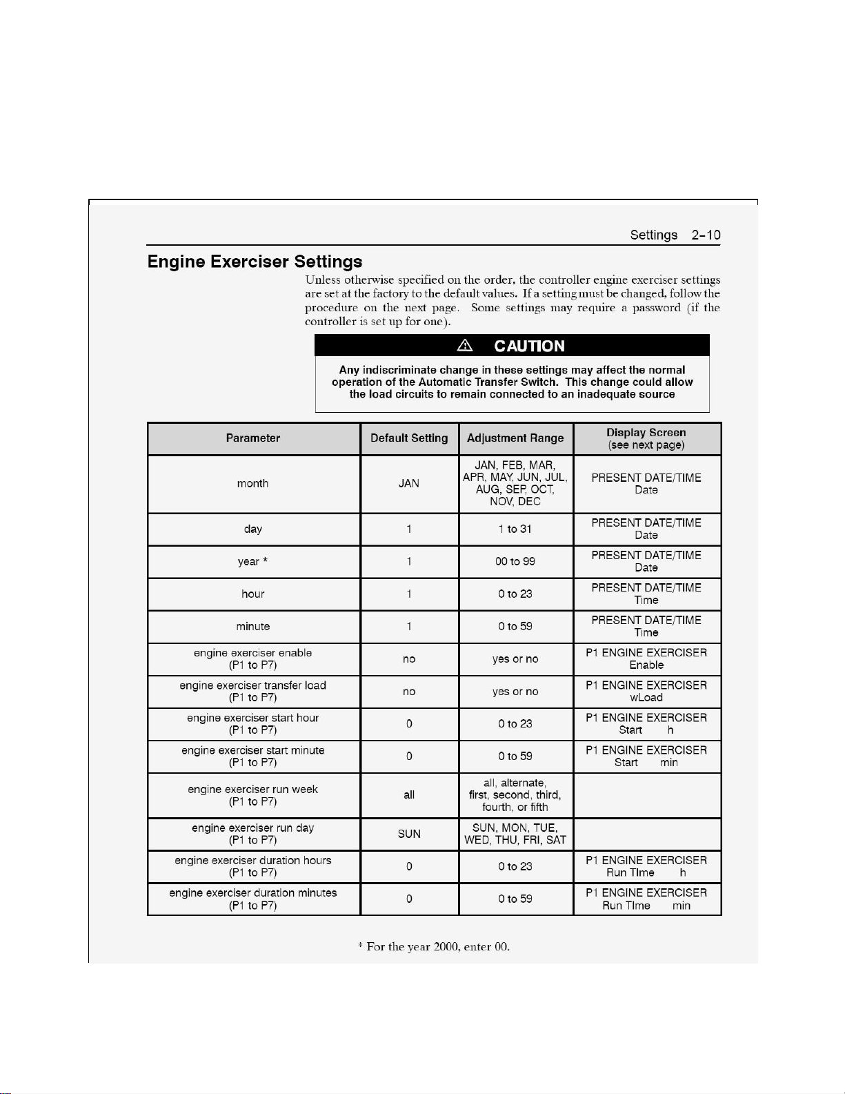
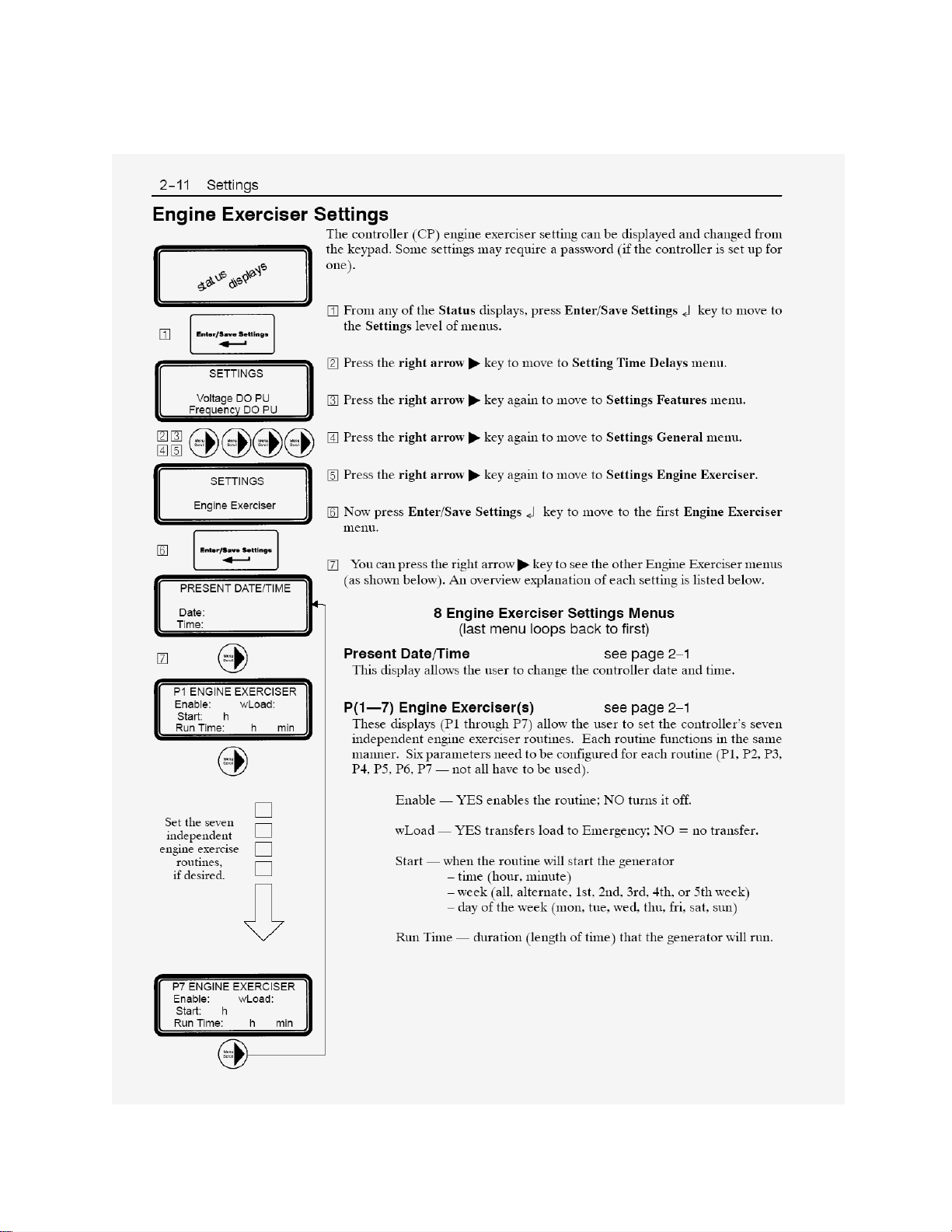
How do I set the engine exerciser?
To set the exerciser, follow the procedures below:
Page 7
Page 8

Is the clock of the engine exerciser accurate?
The engine exerciser clock is moderately accurate. If the generator exercises out of schedule check
the following:
Verify on the event log that the event recorded was an engine exercise.
The PRESENT DATE/TIME setting under the engine exerciser menu should be synchronized with
the present date and time.
The event of engine exercise should fall within any of the enabled P1 to P7 settings.
The generator should not have its own exerciser program.
After checking all of the above and the problem is still there, contact an ASI service technician.
What is an in-phase monitor?
An In-phase monitor is a motor load transfer feature that monitors the voltage and frequency of the two
sources. It ensures that the voltage and the frequency of the two sources are within acceptable phase
angles (in electrical degrees) before the ATS transfers the load between two live sources to avoid
nuisance tripping on the breakers or physical damage to motors.
Page 9
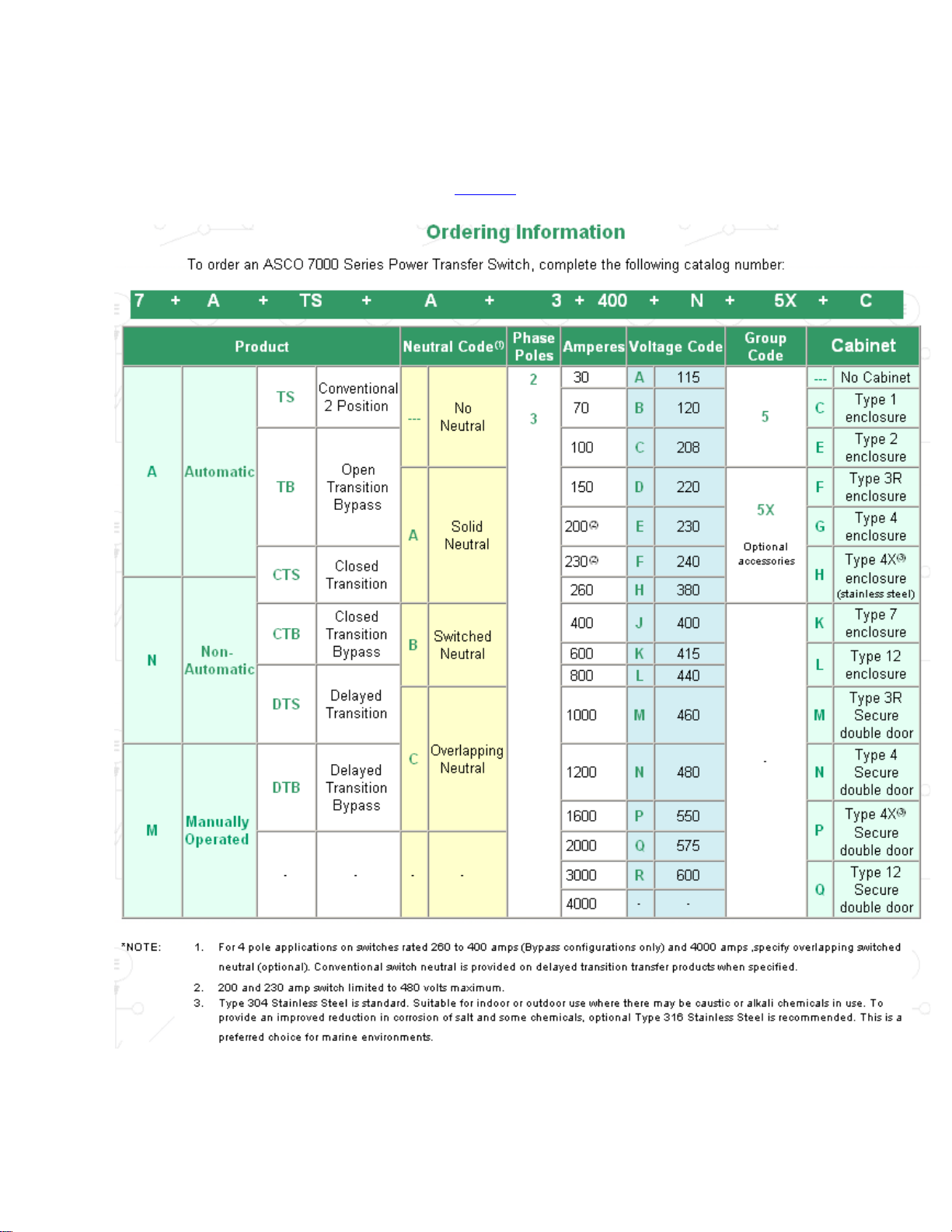
How do I specify an ATS?
To specify the ATS, just follow the catalog no. format below:
NOTE: For the series 7000 suggested specifications click here.
Page 10

What auxiliary control features does the ATS offer?
Click here to view the list of optional control features that the ATB offer.
Where can I get load shed signals?
A load shed signal is provided by an external source. It is then accepted through accessory 30A or 30B
as an add-on circuit that matches the generator capacity with the load. It sends a signal to the ATS to
transfer the load back to the alternate source regardless of its availability. It can be signaled by a removal
of a voltage or contact closure.
.
Page 11

Where can I get pre and post transfer signals on the ATS?
Accessory 31Z is a selective load disconnect that sends a pre- transfer and post transfer signal. The
length of the pre and post transfer delays can be set to 0-5 minutes. Refer to your units wiring diagram
for reference to the correct points on the customer block.
You can get pre-transfer and post transfer signals from an accessory 31Z (Selective load disconnect
contacts) if the transfer switch came with the feature. Refer to the transfer switch wiring diagram and it
should look like figure A (but not exactly the same). If you don’t have this feature on your switch, contact
an ASI technician so they can set-up the feature or call 1-800-800-ASCO (2726) option 1.
Figure A. Selective load disconnect terminal connections
Where can I get source availability signals?
Accessory 18B/18G or source availability contacts are customer contacts added as optional accessory
for the ATS to indicate separate source availability on utility/emergency source regardless of the switch
position. Refer to diagram for example.
You can get source availability signals through an accessory 18B or 18G. The terminal connection would
look like the one shown on Figure B (but not exactly the same). If you don’t have this feature installed on
your switch you may contact an ASI technician or 1-800-800-ASCO (2726) option 1 to have it set-up.
Page 12

Figure B. Acc. 18B and 18G source availability contacts terminal connections
Where can I get switch position contacts?
Accessory 14 is an additional auxiliary contact to indicate switch position. Two sets are standard
(14A/14B). Specify total number of sets if more are required.
Refer to the transfer switch wiring diagram and the terminals connections would look like figure C (But
not exactly the same)
Page 13

Figure C. Acc. 14A and 14B auxiliary contacts terminal connections
Where can I send remote transfer signals?
Feature 17 or a “remote transfer to emergency feature” is a terminal provision for a remote contact that
closes to signal the automatic transfer to emergency and stay in that position while the contact is kept
closed. The transfer switch will retransfer to normal if emergency fails and normal source is available.
What is the default password?
The default password for the Group 5 controller is “1111”. Click here to see how to change the
password.
Page 14

Operation
Can I adjust
the
sensing
of the
controller
?
Yes. Refer to the adjustments listed below (Refer to the
Group 5
User's Guide
for more
information).
Page 15

Page 16

Normal OK
Load on Normal
SETTINGS
How do I change the password?
To change the password, follow the steps below.
1. Go to the Group 5 controller and press the
ESC button until the display shows (with normal
power available and the load connected to normal)
2. Press Enter/Save Settings. Then press
Menu Scroll until the display shows
3. Press Enter/Save Settings. Then
pressMenu Scroll until the display shows
4. If the password below shows “****”, you’ll
need to set DIP switch actuator no. 10 to
“Yes” first, before you can change the
entry.
5. Press Enter/Save Settings and change
the entry using the Increase Value
buttons. Press Enter/Save Settings to
save the entry.
6. After saving the entry, set actuator no. 10
back to “No” to enable the password.
How do I perform a transfer test?
To perform a transfer test, flip the momentary switch to the transfer test position and hold it for 15
seconds or until the switch actually transfers over.
How does the ATS work?
When referring to an open transition transfer switch, the transfer switch main contacts moves in a quick
break - before make mode transition. There is no momentary parallel connection of the two sources and
no extended center-off position during transfer. The transition is quick. The ATS controller monitors the
voltage and frequency of the two sources (upon re-transfer or any transfer between 2 “live” sources) and
ensures that they are in-phase before the load is transferred (if enabled).
How does the engine exerciser work?
The engine exerciser works by closing the engine start contacts and keeping it closed in order to crank and
run the generator. The engine start contacts are kept closed until the exerciser operation timer expires
(approximately 20 minutes). Controller signals the engine start contacts to open up and shut the generator
down completely (after the 5 minute engine cool down period).
For more information please refer to the User Guide.
Page 17

Page 18

Page 19

Is there a preferred source?
Yes, normal (utility) source is considered preferred.
What is the operating temperature of the ATS?
The operating temperature of the 7000 series ATS is 25ºC/ 77ºF.
Others
Literature Request
Click here to view the literatures.
Parts Inquiry
For parts inquiry you may log on at http://www.ascoparts.com/ or dial 1-800-800-ASCO (2726) option 22
Warranty Inquiry
For warranty inquiries, please refer to the standard Warranty published on the website or call 1-800-800ASCO (2726) option 23. (For after sale issues, be sure to take note of the serial no. and catalog no., for a
faster response.) Or contact your local distributor.
Page 20

Product Installation
Can the ATS switch between different voltages?
No. The ATS is designed to get the supply from the source that the transfer switch is connected to. The
switch should get the same voltage coming from Normal and Emergency since the same supply is fed to
the solenoid operator (which has a specific voltage rating). This is the standard design of a 7ATS. If the
switch is to be installed on a facility with different voltage supplied from Normal and Emergency, a
customized design can be done on the factory to meet this requirement.
If it is pre-sale application, contact Application Engineering at 1-800-800- ASCO (2726) option 32. If it is
post sale application, contact ASI at 1-800800-ASCO (2726) option 23.
How do I configure the ATS controller?
The controller configuration depends on the specifications of the switch. Once you’ve verified the
specification based on the Bill Of Materials (BOM), Catalog no. or Serial no., and then you may refer to
the Group 5 User’s Guide for the corresponding adjustments.
Page 21

Type
Design Series
AMPS
Manual Number
7ATS
D
30 - 230
381333-229E
E
260 - 400
381333-127G
J
260 - 600
381333-283B
H
600 - 1200
381333-202C
G
1000 - 4000
381333-414A
7ACTS
E
150 - 400
381333-128E
J
150 - 600
381333-284A
H
600 - 1200
381333-203D
G
1000 - 4000
381333-414A
7ADTS
E
150 - 400
381333-129C
J
150 - 600
381333-285A
H
600 - 1200
381333-204B
G
1000 - 4000
381333-414A
AMPS
7ATB Manual Numbers
7ACTB Manual Numbers
7ADTB Manual Numbers
150 - 600
381333-307A
381333-308A
381333-309
800 - 1200
381333-193C
381333-194B
381333-195A
1600 - 4000
381333-132F
381333-136E
381333-140D
Type
Manual Number
7MTS
381333-205A
7NTS
381333-151B
How do I install an ATS?
To install the ATS you just need to follow the installation procedures on the Operator’s Manual and the
Outline and Mounting Diagrams.
Operator’s Manual
Page 22

Outlines and Mounting Diagrams
Page 23

What is the maximum length of control line run?
The maximum length of a control line run depends on what type and size of control wire is used. The
NEC requirements still rule on this case.
Where can I get the weight and dimensions of the ATS?
Click here to get the standard shipping weights of the ATS. For more detailed info, refer to the Outline
and Mounting Diagrams
What size cable or wire can I use for the power connections of the ATS?
Click here for the recommended wire sizes. You may also refer to the Outline and Mounting Diagrams for
more information.
When do I need to connect the neutral?
You need to connect the neutral:
If it is required by the local code on the installation.
If the ATB is switching line to neutral loads.
If the transfer switch is installed for service entrance.
NOTE: All local code requirements should always be followed.
Page 24

How do I specify the type of neutral?
A Solid Neutral means that the system neutral conductors (load, emergency and utility) are solidly
bonded to a common lug and a copper plate. The connection of the 3 neutral conductors is fixed to the
common lug. It is denoted by an A2 (2 pole) or A3 (3 pole) in the catalog.
A Switched Neutral means that the load neutral conductor connection is switched between the
emergency neutral and the utility neutral. It is denoted by a B2 (2 pole) or B3 (3 pole) in the catalog
number string.
An Overlapping Neutral means that the load neutral conductor is connected to both the normal and
emergency neutrals before the transfer and then remains in the position where the switch transferred
to. It is a make before break neutral design. It is denoted by a C2 (2 pole) or C3 (3 pole) in the catalog
number string.
What is the Withstand Current Rating (WCR) of my transfer switch?
Refer to Publication 1128-R14.
Which breakers are tested with an ASCO transfer switch?
Refer to Publication 1128-R14 for tested breakers for ASCO switches.
Service
Can I modify the voltage rating of the ATS?
To modify the voltage rating of the ATS, you’ll need to replace the coil kit and set the factory jumpers of
the control panel. Contact ASCO Services for a service technician (1-800-800-ASCO).
How can I extend feature 1C timer?
You can extend the time delay before engine start with any backup power accessory. The feature needs
to be set-up by an ASCO Service technician.
How do I contact a service technician?
Call 1-800-800-ASCO (2726) and choose option 2 then 3.
How can I convert an ACTS to an ATS?
Contact ASCO Services (1-800-800-ASCO).
How do I convert an ATS to an ADTS?
This is not possible on the field. You may have the switch shipped to the factory for the modification or
you may opt to replace the ATS for practical reasons.
How do I convert the ATS from 1Φ to 3Φ?
Preferably contact ASCO Services to review wiring (1-800-800-ASCO).
How will I know if the controller is damaged?
Page 25

If the display doesn’t work.
If there are extensive signs of burns on the PC board.
If the OP and NR relays are damaged.
Page 26

What does this alarm message mean?
Below are the definitions of the alarm messages that pop-up on the controller display.
Page 27

Page 28

What should I do if the indicator lights are faulty?
Check the wires to the door controls for any signs of burns.
Check if there is voltage across the pilot lamp terminals.
o
If there is no supply, disconnect the gray plug on J10 of the Group 5 PC
reconnect it again to ensure proper fitting.
o If there is voltage across the pilot lamp terminals, order a replacement door mounted control.
If there is none, check the control panel for possible errors.
Check if the voltage reading on the Group 5 control panel is correct.
o Check the readings with the voltage rating of the ATS.
o If there’s none, check the voltage across the lugs. If the correct voltage is supplied, check
the harness. If it is not the harness then the problem is on the controller.
board and
Why won't the ATS retransfer to normal?
Normal is unavailable
The retransfer to normal inhibit is activated. (Check the wiring diagram
for feature 34A terminals. The jumper could be loose or disconnected)
The solenoid operator is damaged.
Emergency source voltage is not correct.
The ATS has feature 6C and 6D enabled on the switch.
The time delay hasn’t lapsed yet.
Control panel error
Mechanical problem
Why won't the ATS start the generator?
There is incorrect wiring of the engine start.
The control wires are loose.
The generator is not set to auto.
There is an active alarm on the generator.
The NR relay failed (Control panel error)
Why won't the ATS transfer to Emergency ?
Emergency is unavailable.
The Transfer to Emergency Inhibit is activated.
The Load Shed from Emergency feature is activated
The solenoid operator is damaged
The ER relay is damaged
The controller is damaged
There is mechanical failure.
Why won't the engine exerciser work?
The Engine Exerciser settings are not configured properly (Refer to the Group 5 User’s Guide)
The Generator has a built-in engine exerciser
The Controller firmware needs to be upgraded
Page 29

Why won't the generator shut-off?
Normal is unavailable (Check if the right voltage is supplied on the Normal lugs or if Normal Accepted
light is ON)
The generator is in cool down mode. Wait until the cool down timer times out.
The selector switch for manual engine start is set to run. Switch it to AUTO.
The TS (AUX1) auxiliary contact for engine start is stuck-up. Contact a service technician to calibrate
the cam switches.
The NR relay is damaged. Replace the Group 5 controller.
There is a problem on the generator.
Page 30

Wiring
Where do I connect the engine start wires?
The engine start contacts are also known as feature 7 and 8.
Feature 7 – Contact that closes to send an engine start signal
Feature 8 – Contact that opens to send an engine start signal
Refer to the transfer switch wiring diagram for the terminal connections. To request for a wiring diagram,
take note of the Serial number, BOM number, and the Catalog number of the transfer switch and call 1800-800-ASCO (2726) option 33.
How can I re-wire my power manager connections?
Follow the wiring diagram attached on the Power Manager’s Operator’s Manual.
 Loading...