

Page 1
ASCO 5310 User’s Guide
A
A
A
A
User’s Guide
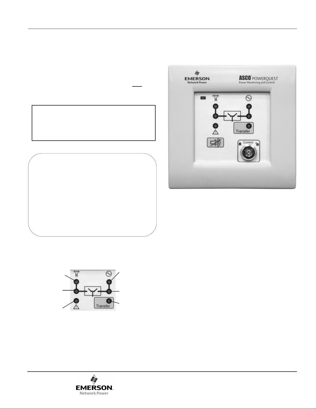
The ASCO Catalog 5310 ATS Remote Annunciator provides
remote visual status reporting and push-button testing of one
ASCO automatic transfer switch.
This User’s Guide provides operation information after
ATS Remote Annunciator has been installed and configured.
It also includes basic troubleshooting.
Refer to Installation Manual 381333-317
for mounting, wiring, and configuration.
TABLE OF CONTENTS
Operation .2-3
Control key switch .
larm silence button .
Transfer test .
Flashing light .
Reset button .
Troubleshooting .
the
page
2
2
2
3
3
4
ATS Remote Annunciator
Catalog 5310
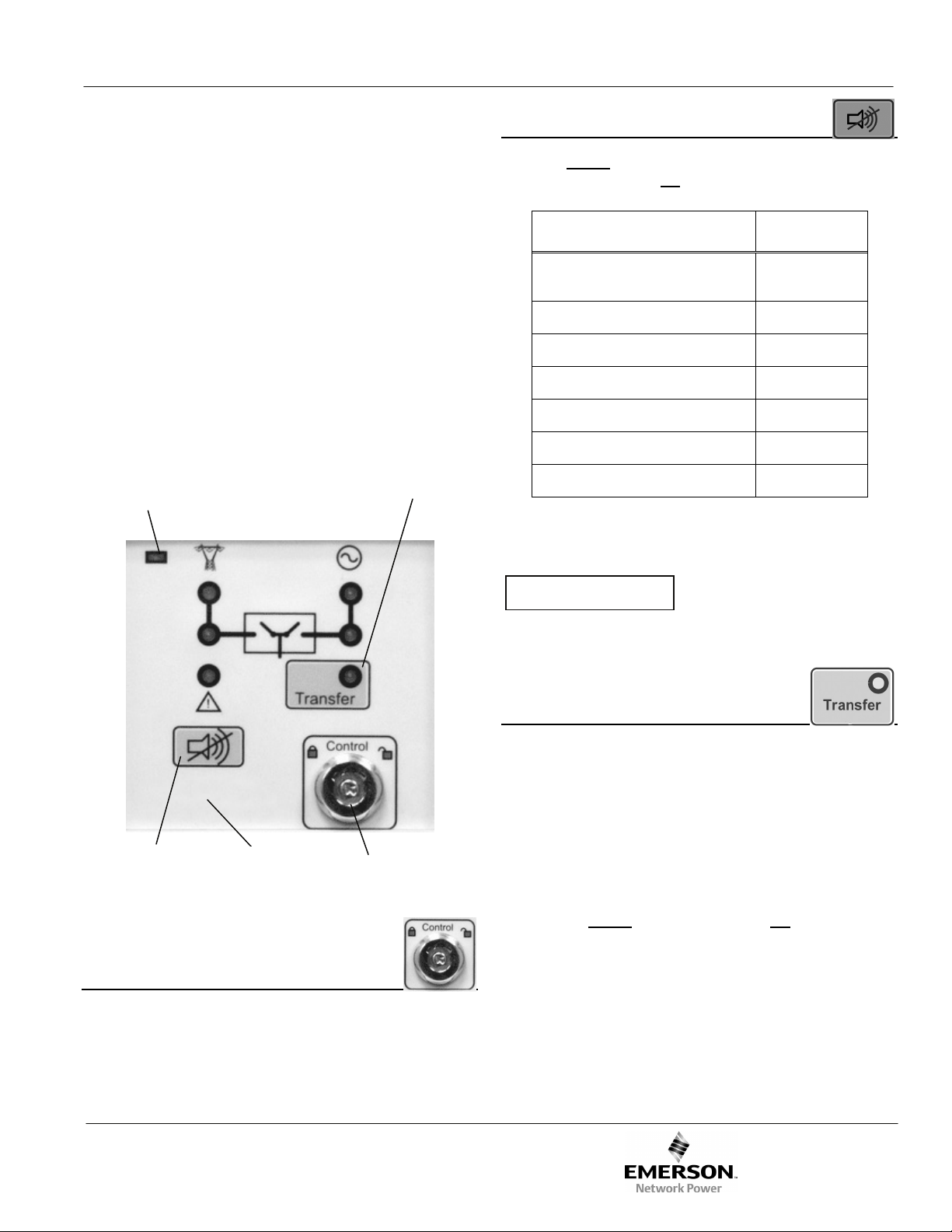
Figure 1 shows the status lights and Transfer button.
The Normal source acceptable light (upper left) is on when
the ATS controller accepts the utility source. This light is off
when the utility has failed.
Generator
Normal source
acceptable
TS connected
to Normal
TS and
common
alarm
Utility
Figure 1: Status lights and Transfer button
Emergency
source
acceptable
TS connected
to Emergency
Transfer time
delay active
The Emergency source acceptable light (upper right) is on
when the ATS controller accepts the generator source. This
light is off when the generator is unacceptable (low or high
voltage, low or high frequency, or generator is off).
The ATS connected to Normal light (center left) is on when the
load is being fed by the utility. It is off when it is disconnected
from the utility.
The ATS connected to Emergency light (center right) is on
when the load is being fed by the generator. It is off when it is
disconnected from the generator.
The ATS & common alarm light (lower left) is on when an
ATS or common alarm is received. It is off when the alarm is
cleared. See Alarm silence button, page 2; Troubleshooting,
page 4.
The Transfer light (lower right) is blinking when a load
transfer time delay is active. It is off when there is not a load
transfer time delay active. See Flashing light (time delay),
page 3.
381333-316 A
381333-316 A ASCO Power Technologies Page 1
Page 2
User’s Guide ASCO 5310
E
Operation
The ASCO 5310 ATS Remote Annunciator communicates
with an ASCO automatic transfer switch (ATS) to report its
status. The ATS Annunciator polls the ATS and obtains its
status. Lights indicate if the ATS is connected to the normal
source or the emergency source. Source acceptability status
for the ATS is also shown. In addition, the ATS Remote
Annunciator can send commands to the ATS to control its
operation.
A control key switch prevents unauthorized operation. A
transfer test button simulates a normal source outage and
transfers the load to the emergency source, if acceptable. The
same button is used to retransfer the load back to the normal
source. When the button is held, any active time delay is
cancelled. A lights in the button indicates if the ATS is in the
test mode and if a time delay is active. See Figures 1 and 2.
Power ON
light
Utility
Transfer button
Generator
2 Alarm silence button
Press and release the alarm silence button to turn off the
audible alarm sound. Do not hold the button. These are the
possible alarm conditions:
Alarm Condition Product
communication error
locked out 4000 & 7000
ATS position error 4000 & 7000
failure to synchronize 4000 & 7000
extended parallel 4000 & 7000
controls not in automatic 4000 & 7000
ATS bypass active 7000
Alarms can be specific to the ATS or a general (common)
communications error or any configured alarm via the Power
Manager.
NOTIC
Before using the transfer button, be sure conditons
are safe for running the generator and for load
transfer.
185, 300,
4000, 7000
Alarm silence
button
hidden reset
button
Figure 2: Control buttons
Control key switch
1 Control key switch
The Control key switch prevents unauthorized operation of
the ATS Remote Annunciator. The key can be removed in
either the locked or unlocked positions. In the locked position
(left), the buttons do not operate. In the unlocked position
(right) all buttons function.
3 Transfer test
The following operation starts the generator and transfers the
load. Be sure that conditions are safe to do this operation.
3-1 Load Transfer to Emergency source
To transfer the load from the normal source to the emergency
source, follow this procedure:
1. Turn the Control key right to the unlocked position.
2. Press and release
button).
3. Observe that the generator light comes on (generator
acceptable).
4. Observe that the light in the corner of the button blinks
(transfer time delay active, if used).
5. Observe that the ATS connected lights change position
(transfer from normal to emergency).
6. To retransfer the load back to Normal go to section 3-2.
Transfer button (do not hold the
Page 2 ASCO Power Technologies 381333-316 A
Page 3

ASCO 5310 User’s Guide
Note:
If Feature 2B transfer to emergency time delay is used, the
transfer may not occur for up to 61 minutes (depending upon
the ATS and the setting in the controller).
To bypass (cancel) this time delay, press the Transfer button
again and hold
beep.
it for more than 5 seconds until you hear a
5 Reset button +
A hidden reset button is located just below the Alarm Silence
button (see Figure 1). The Control key switch must be
unlocked
together as follows:
. The reset button and alarm silence button work
3-2 Load Retransfer to Normal source
To retransfer the load from the emergency source back to the
normal source, follow this procedure:
1. Turn the Control key right to the unlocked position.
2. Press and release
button).
3. Observe that the utility light comes on (utility acceptable).
4. Observe that the light in the corner of the button blinks
(retransfer time delay active, if used).
5. Observe that the ATS connected lights change position
(transfer from emergency to normal).
6. Turn the Control key left to the locked position, then
remove it.
Note:
If Feature 3A retransfer to normal time delay is used, the
transfer may not occur for up to 61minutes (depending upon
the ATS and the setting in the ATS controller).
To bypass (cancel) this time delay, press the Transfer button
again and hold
the Transfer button (do not hold the
it for more than 5 seconds.
5-1 Soft reboot reset
(keeps user’s configurations)
The soft reboot retains the configurations that you have made.
To perform a soft reboot, press and hold the hidden reset
button and the alarm silence button together for less than 3
seconds. The configuration parameters remain unchanged.
5-2 Hard reboot reset
(factory default configuration)
The hard reboot resets all user configuration parameters to
factory default settings. The configurations that you have
made will be erased. To perform a hard reboot, press and hold
the hidden reset button and the alarm silence button together
for more than 15 seconds
parameters are:
IP Address 169.254.1.200
Subnet 255.255.255.0
Gateway
Other factory default parameters could be checked through
Ethernet interface with computer.
. The default configuration
4 Flashing light (time delay)
The light in the Transfer button flashes when a transfer time
delay is active. The faster the blinking, the shorter the delay:
1/10 sec. blink 0 to 5 second transfer delay
1/4 sec. blink 5 to 15 second transfer delay
1/2 sec. blink 15 to 60 second transfer delay
1 sec. blink over 1 minute transfer delay
381333-316 A ASCO Power Technologies Page 3
Page 4

User’s Guide ASCO 5310
Troubleshooting
Numbe
r
1 Power ON light is off
2 The power ON light is blinking.
3
4 Buzzer is beeping continuously.
Transfer button does not work
(load transfer does not occur).
Symptom Probable Cause Recommended Action
The DC or AC power source is
inadequate or off.
The unit keeps on resetting due
to watchdog-reset possibly due
to corruption of software.
Button not held long enough.
ATS Annunciator could have
changed to default settings.
Communication with the Power
Manager may have stopped.
Restore the DC or AC power supply.
Check the terminals, fuse, circuit breaker.
Refer to Installation Manual 381333-317.
Try to reprogram the unit with the latest
software.
Contact ASCO Services for replacement.
800-800-ASCO or
customercare@asco.com
Hold the button for at least 5 seconds
until you hear a beep.
Refer to Installation Manual 381333-317.
Use the configuration details entered on
page 2; reconfigure the ATS Annunciator.
Refer to Installation Manual 381333-317.
Check the Ethernet connections:
ATS Annunciator to the LAN and
Power Manager to the LAN.
5
6
Communication alarm occurs but
all configurations are correct.
A light does not come on when a
corresponding button is pressed.
Communication protocol may not
the same as that of the Power
Manager (if present).
ATS Annunciator is
not functioning properly.
Refer to Installation Manual 381333-317.
Verify that the protocol on both devices is
the same.
Contact ASCO Services for replacement.
800-800-ASCO or
customercare@asco.com
Page 4 ASCO Power Technologies 381333-316 A
 Loading...