

Emerson Anderson Greenwood 81P, Anderson Greenwood 81P Series Maintenance Instructions Manual
Page 1
ANDERSON GREENWOOD TYPE 81P DSO PRESSURE RELIEF VALVES
MAINTENANCE INSTRUCTIONS
Before installation these instructions must be fully read and understood
TABLE OF CONTENTS
1. General ........................................................... 1
2. Valve repair (-4, -8 orifice) ............................ 1
3. Valve repair (G, J orifice) ............................... 3
4. Valve adjustment ........................................... 4
5. Seat leakage .................................................. 5
1 GENERAL
The Anderson Greenwood Type 81P Direct
Spring Operated (DSO) Relief Valve is a direct
acting spring loaded valve for liquid service and
uses a plastic seat and O-ring seals.
The intent of these instructions is to acquaint
the user with the maintenance of this product.
Please read these instructions carefully. This
product should only be used in accordance
with the applicable operating instructions and
within the application specifications of the
original purchase order. The installation and
Operational Safety Instructions (available at
www.valves.emerson.com) should be fully read
and understood before returning this product to
service after maintenance.
WARNING
An attempt to repair this product by unauthorized
or unqualified persons voids the product warranty
and may cause damage to equipment and serious
injury or death to persons.
The product is a safety related component
intended for use in critical applications.
Theimproper application, installation or
maintenance of the product or the use of parts
or components not manufactured by Anderson
Greenwood may result in a failure of the product.
Any installation, maintenance, adjustment, test,
etc. performed on the product must be done
in accordance with the requirements of all
applicable Anderson Greenwood procedures and
instructions as well as applicable National and
International codes and standards.
2 VALVE REPAIR (-4, -8 ORIFICE)
Refer to Figure 1
2.1 Disassembly
2.1.1 Relieve spring tension by turning the
pressure adjusting screw counterclockwise.
2.1.2 Remove inlet bushing, bushing seal and
valve internals.
2.1.3 Separate nozzle from guide by hitting
top of spindle on soft surface. Remove
spindle seals.
2.2 Repair
2.2.1 Hold spindle by skirt O.D. in soft jaw vise
and replace seat.
2.2.2 Examine nozzle and polish out any
scratches or nicks. Replace if necessary.
2.2.3 To obtain better seat seal with PTFE at
low set pressures, burnish seat against
nozzle by chucking spindle in lathe and
holding nozzle against spindle. Burnish
with small force and for short time as
PTFE deforms easily.
2.3 Assembly
Assemble in reverse order of
disassembly. Lubricate the parts listed
below with the specified lubricant. Make
sure the nozzle is fully and squarely
seated in guide.
LUBRICANTS
Part Set pressure Lubricant
Spindle seals 50-1000psig (3.4 - 69.0barg) Dow Corning FS3451
Above 1000psig (69.0barg) Desco 600
Thread and adjusting bolt tip All Dow Corning 33
Emerson.com/FinalControl © 2017 Emerson. All rights reserved.
Engineering Doc. #05.9040.072 Rev. K
VCIOM-01056-EN 16/12
Page 2
ANDERSON GREENWOOD TYPE 81P DSO PRESSURE RELIEF VALVES
MAINTENANCE INSTRUCTIONS
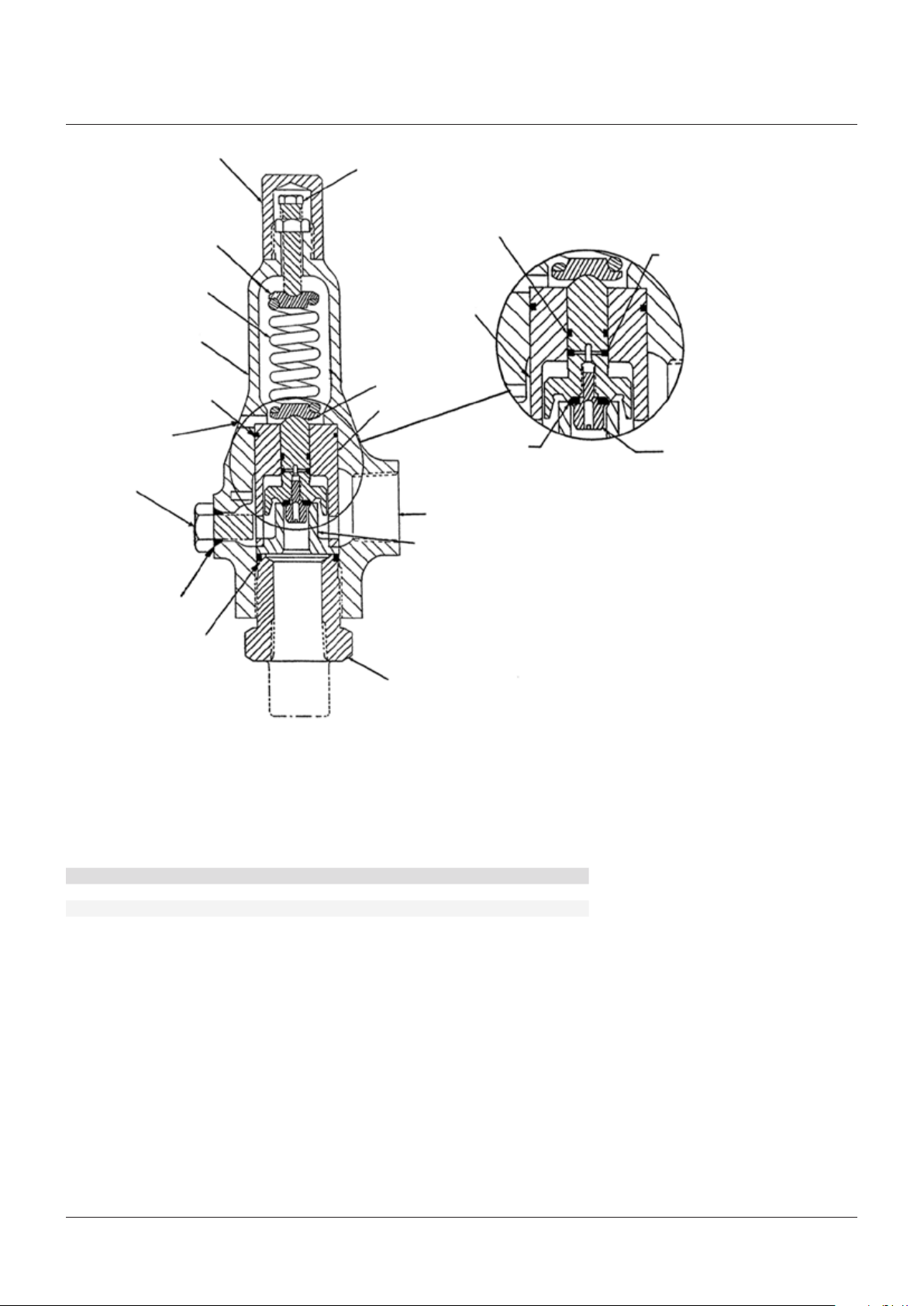
Spring washer
Vent
Plug
Spring
Body
Guide seal
Seal
Cap
Pressure adjustment screw
Spindle seal
Spindle skirt
Spindle
Guide
Outlet
Nozzle
Seat
Drag seal
Seat retainer screw
Seat detail
(-4 illustrated)
Bushing seal
Bushing
FIGURE 1
-4, -8 ORIFICE
2.4 Soft goods repair kit
The part numbers for soft goods repair kits are listed below. Each kit contains the seat and
seals for all pressure ranges and the lubricant specified in paragraph 2.3.
MATERIAL
Orifice NBR FKM EPR
-4 04.4805.029 04.4805.032 04.4805.071
-8 04.4805.029 04.4805.032 04.4805.071
2
Page 3

ANDERSON GREENWOOD TYPE 81P DSO PRESSURE RELIEF VALVES
MAINTENANCE INSTRUCTIONS
Cap
Pressure adjustment screw
Spring washer
Bonnet retainer ring
Outlet
Spring
Vent
Bonnet
flange
Seal
Bonnet
Flange bolt
Spindle
Seal
Nozzle
Body
Drag seal
Guide
Seal
Spindle seal
Seat
Seat retainer screw
Seat detail
Plug
FIGURE 2
G, J ORIFICE
3 VALVE REPAIR (G, J ORIFICE)
Refer to Figure 2
3.1 Disassembly
3.1.1 Relieve spring tension.
3.1.2 Remove spring bonnet and valve internals.
3.1.3 Separate nozzle from guide by hitting top of spindle on soft surface.
3.2 Repair
3.2.1 Hold spindle by skirt O.D. in soft jaw vise and replace seat.
3.2.2 Examine nozzle and polish seating surface as required. Replace if necessary.
3.3 Assembly
Assemble in reverse order of disassembly. Lubricate the parts listed below with the
lubricant specified. Make sure the nozzle is fully and squarely seated in guide.
3
Page 4

ANDERSON GREENWOOD TYPE 81P DSO PRESSURE RELIEF VALVES
MAINTENANCE INSTRUCTIONS
LUBRICANTS
Part Set pressure Orifice Lubricant
Spindle seals 50-300psig (3.4 - 20.7barg) G Dow Corning FS3451
50-100psig (3.4 - 6.9barg) J Dow Corning FS3451
Spindle seals Above 300psig (20.7barg) G Desco 600
Above 100psig (6.9barg) J Desco 600
Thread and adjusting bolt tip All G and J Dow Corning 33
3.4 Soft goods repair kit
The part numbers for soft goods repair kits are listed below. Each kit contains the seat and
seals for all pressure ranges and the lubricant specified in paragraph 3.3.
MATERIAL
Orifice NBR FKM EPR
G 04.4805.030 04.4805.033 04.4805.072
J 04.4805.031 04.4805.034 04.4805.073
4 VALVE ADJUSTMENT
4.1 General
The only adjustment required for the Type 81P valve is the set pressure. The reseat pressure
is not adjustable. Reseat will occur at approximately 75% to 80% of set pressure.
4.2 Proof test
The spindle seals and bonnet seal of the Type 81P valve shall be checked for integrity by
pressurizing the outlet with 30psig (207 kpag) of air. A soap solution shall be applied to the
exterior joints of the bonnet, including across the vent hole. There shall be no evidence of
leakage.
4.3 Set pressure
Type 81P liquid valves marked with the UV code stamp (relief capacity in volume of liquid per
time, GPM) shall be set using water and a 50 gallon pressure vessel.
When setting the valve using water, turn the spring adjustment screw on the bonnet in most
of the way. Increase the pressure to 107% ± 2% of nameplate set and back out screw until
the valve 'pops' or 'gushes' liquid. Set pressure is defined as 93% of that pressure where the
valve 'pops'.
Example liquid English liquid International liquid
Nameplate set = 75psig 5.2barg
'POP' or 'GUSH' = (107% ± 2%) 75 = 78.75 to 81.75psig (107% ± 2%) 5.2 = 5.4 to 5.6barg
Actual 'POP' = 80psig 5.5barg
Actual set = 80 (.93) = 74.4psig 5.5 (.93) = 5.1barg
4
Page 5

ANDERSON GREENWOOD TYPE 81P DSO PRESSURE RELIEF VALVES
MAINTENANCE INSTRUCTIONS
If the Type 81P liquid valve is not marked with the UV code stamp and if a water source is
not available valves with set pressures greater than 750psi (51.7barg) may be set on air
by adjusting the spring to obtain first crack at 95% of set pressure. The valve should not be
popped on air as this may damage the seat. For set pressures below 750psi (51.7barg), the
81P should only be set pressure adjusted using the water method above.
Note: valves with relief capacity in GPM must be set using water if the valve will bear the 'VR'
repair symbol stamp.
Type 81P air valves shall be set using an accumulator large enough to accurately measure
set pressure. Turn the spring adjustment screw on bonnet in most of the way. Increase
pressure to desired level and back out screw until valve pops. Lock screw with jam nut and
retest. Readjust as required.
4.4 Adjustment tolerances
Set pressure range Valve operating characteristics Tolerance or limit
Above 70psig (4.8barg) Set pressure ± 3% of nameplate set
70psig (4.8barg) and below Set pressure ± 2psig
100psig (6.9barg) and above Cracking pressure 92½% of nameplate set
50psig (3.4barg) to 99psig (6.8barg) Cracking pressure 80% of nameplate set
5 SEAT LEAKAGE
5.1 If the valve leaks after repair, check for the following:
5.1.1 Full and even seating of nozzle and guide.
5.1.2 Foreign particles trapped between the seat and nozzle. If any are found they may have
damaged the seat making it necessary to replace it.
5.1.3 Correct seat material for the valve set pressure. If item 1 and 2 reveal no evident seat
leakage source, the procedures described in section 5.2. may be used to eliminate seat
leakage. Section 5.2 applies only to PTFE seated -4 or -8 orifice type 81P with nameplate
set pressures that do not exceed 250 psig (1724 kPag).
5.2 Seat sealing procedures
Heat the valve for 15 to 30 minutes in an oven preheated to 250-265°F (121-129°C). A concentrated
heat source such as a heat gun or open flame must not be used. After the valve has air-cooled to
room temperature, retest per section 4 to ensure seat tightness. If results have not improved, the
valve should be disassembled and the seat replaced.
5
 Loading...