

Emerson Anderson Greenwood 443, Anderson Greenwood 400, Anderson Greenwood 449, Anderson Greenwood 453, Anderson Greenwood 463 Installation And Maintenance Instructions Manual
...
ANDERSON GREENWOOD SERIES 400 PISTON PILOT POPRV
InstallatIon and MaIntenance InstructIons
Before installation these instructions must be fully read and understood
As capacity relief of thesystem is satisfied,
system pressure will begin to decrease. When
it does, the pilot will actuate and direct system
pressure to the main valve dome. This closes
the main valve.
The pilot is the non-flowing type. With the main
valve open and relieving at steady pressure,
no process gas or fluid flows through the pilot.
When process pressure changes, the pilot
actuates to change the lift of the main valve
piston. During these actuations a small amount
of gas or fluid from the main valve dome flows
through the pilot and is discharged thru the
pilot exhaust.
The set pressure range is 100 psig to 1480 psig.
1.2 Installation
Either or both inlet and outlet may be
standard ANSI flanges or ANSI pipe threaded
connections and are to be installed in
accordance with accepted piping practices.
When remote pressure pick-up is used the pilot
TABLE OF CONTENTS
1 General valve description and start-up ...... 1
2 Main valve maintenance .............................. 2
3 Pilot maintenance ........................................ 7
4 Pilot set pressure adjustment .................. 14
5 Valve assembly testing .............................. 20
6 Pilot set pressure field test procedure .... 24
7 Soft goods repair kits................................. 25
8 Pilot accessories ........................................ 26
9 Assembly and maintenance equipment ... 26
1 GENERAL VALVE DESCRIPTION AND
START-UP
1.1 General
The Anderson Greenwood Series 400 valve is
designed for modulating action. The main valve
will open at nameplate set, but only an amount
proportional to the relieving capacity required.
As process pressure increases, the valve will
open more and be in full lift at 110% of set.
The main valve uses the principle of
pressurizing the top or large area of a
differential area piston with line pressure
to hold the piston closed up to set
pressure. At set pressure, the pilot relieves,
depressurizing the volume above the piston,
the main valve dome, and the piston lifts
permitting discharge from the main valve.
supply tube is connected to a remote location
rather than to the inlet neck of the valve. A
block valve in the remote pilot supply line is not
recommended. If one is used it must be opened
before pressurizing the main valve.
NOTE
Remote pressure pick-up piping must have the
equivalent flow area of 3/8” tubing for lengths up to
100 feet. For lengths greater than this, consult factory.
1.3 Start-up
There must be pressure at the valve inlet or at
the pilot inlet/sense port for valves with remote
sense to establish a differential force across
the piston and ‘load’ it in the closed position.
Pressure must pass through the pilot and exert
force on the top of the piston. On normal plant
start-up the valve will close itself as pressure
increases.
Block valves are often used under safety valves
to isolate them when maintenance is required.
When putting the safety valve in service be sure
the block valve is fully opened. If the block valve
is opened after system start-up, the safety
valve may briefly vent before the dome gets
pressurized to close the main valve seat.
Engineering Doc. #05.9040.270 Rev. K
Emerson.com/FinalControl
© 2017 Emerson. All rights reserved.
VCIOM-06020-EN 18/02
ANDERSON GREENWOOD SERIES 400 PISTON PILOT POPRV
InstallatIon and MaIntenance InstructIons
1.4 Maintenance
Anderson Greenwood recommended main valve
and pilot maintenance procedures including
pilot set pressure adjustment and valve
assembly testing are described in the following
paragraphs. Following these procedures in
a regular pressure relief valve maintenance
program appropriate for the specific operating
conditions will ensure satisfactory valve
performance and provide optimum service life.
Should the pressure/media requirements of a
pilot operated pressure relief valve be outside
the capabilities of the repair facility, contact
Anderson Greenwood for specific instructions
before starting any maintenance activity.
This manual is provided as a general guide for
the maintenance of the safety valves described
herein. It does not include procedures
covering all valve configurations and variations
manufactured by Anderson Greenwood. The
user is advised to contact Anderson Greenwood
or one of our authorized representatives for
assistance with valve configurations and
variations not covered in this manual.
2 MAIN VALVE MAINTENANCE
2.1 Disassembly
Before beginning disassembly, bleed off any
pressure trapped in the main valve or pilot.
Refer to Figure 1A (piston/seat Type XX3) and
Figure 1B (piston/seat Type XX9) for parts
description and location.
Remove cap (Item 17) from the body (Item 1).
Remove the liner seal (Item 6), liner (Item 5)
and piston (Item 10). Remove the soft goods
from the piston. If the piston is equipped with
a wedge ring (Item 23), clean and retain for
use during assembly. The dipper tube (Item 4)
is swaged in place and no attempt should be
made to remove it. The nozzle (Item 3) should
not be removed unless it is damaged or the
nozzle seal (Item 2) is leaking.
NOTE
Do not remove lock pin and lift adjusting bolt (Items11
and 12)
on valves so equipped unless nozzle is
removed. This bolt controls the piston lift and hence
the valve’s relieving capacity. If either or both the
nozzle and lift bolt were removed, then lift must be
reset following the procedure of paragraph 2.3.3
(TypeXX3 or paragraph 2.3.4 (Type XX9).
2.1.1 Nozzle and nozzle seal disassembly
Refer to Figure 2 for parts description and
location.
1. Remove lock pin and lift adjusting bolt from
piston, if applicable.
2. Place liner in body and piston, without seat
or seat retainer, into liner and on top of
nozzle.
3. Place appropriate spacer (see Table I) on top
of piston and then the cap over the spacer.
4. Thread the appropriate number of cap bolts
(see Table I) into threaded holes on top of
body. If two bolts are used, they should be
180° apart. When using four bolts, they
should be 90° apart. Always use the shortest
cap bolts supplied with the valve unless
all cap bolts are required. For example,
the1” Type 40/50 is equipped with two 1.50”
long bolts and two 1.88” long bolts but only
the two 1.50” long bolts should be used.
However, the 2” Type 40/50 is equipped with
two 1.25” long bolts and two 1.62” long bolts
and all four bolts are required for nozzle
installation.
5. Tighten cap bolts evenly to the torque listed
in Table I to compress nozzle seal.
6. Use a punch or bar with a light hammer
and tap on the nozzle retainer teeth to
loosen the nozzle retainer. Unthread nozzle
retainer approximately ½ turn.
7.
Loosen cap bolts to remove load from nozzle.
Remove components from main valve.
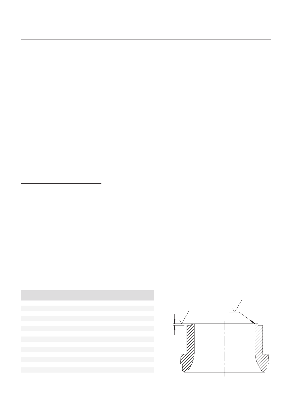
2.2 Main valve nozzle rework
Should the main valve nozzle seating face
become nicked or scratched such that the main
valve seat does not seal, the imperfections
can be removed by polishing the seating face
with 400 grit sandpaper. If necessary, the
nozzle may be removed from the body and
the nozzle seating face (only the seating face)
may be remachined and/or polished using
400 grit sandpaper on a flat surface plate. The
resurfaced nozzle must be within the limiting
dimensions shown in the table and figure
below. If the resurfaced seating face standoff is
less than the minimum projection height listed,
the nozzle must be replaced.
Valve size and type
X = Main valve piston/seat type, 3 or 9
1/1.5 x 2 Type 44X/45X (D, E and F orifice) .045
1.5 x 2/3 Type 44X/45X (G and H orifice) .040
2” Type 44X/45X .035
3” Type 44X/45X .035
4” Type 44X/45X .035
6” Type 44X/45X .035
8” Type 44X/45X .035
1.5” Type 46X .035
2” Type 46X .035
3” Type 46X .035
4” Type 46X .030
6” Type 46X .030
8 x 88 Type 46X .030
8 x 10 Type 46X .030
10” Type 46X .030
Min. nozzle projection
height (in)
Minimum
projection
32
32
.010
R.020
2

ANDERSON GREENWOOD SERIES 400 PISTON PILOT POPRV
InstallatIon and MaIntenance InstructIons
2.3 Assembly
2.3.1 Nozzle and nozzle seal installation
1. Place nozzle seal and nozzle in body.
2. Place nozzle retainer over nozzle and thread
into body until it stops on nozzle shoulder.
Do not lubricate nozzle retainer threads or
mating body threads.
3. Repeat steps 3 through 5 of disassembly
procedure to compress nozzle seal.
Thread nozzle retainer into body as seal is
compressed to keep nozzle retainer from
binding against piston.
4. Use a punch or bar with a light hammer and
tap on the nozzle retainer teeth to snug the
nozzle retainer threads.
5. Loosen cap bolts to remove load from
spacer.
6. Remove spacer from valve.
2.3.2 Soft goods installation and main valve
reassembly
Refer to Figure 1A (piston/seat Type XX3) and
Figure 1B (piston/seat Type XX9) for parts
description and location.
2.3.3 Type XX3 piston and seat
Clean and apply a light coating of Dow Corning
No. 33 or equivalent silicone lubricant on all
threads. Install new seat and reassemble seat
retainer and seat retainer screw or screws.
On 1” to 4” Type 43/53 and 1.5” to 3” Type 63
valves, if either or both the nozzle and lift bolt
were removed, then lift needs to be set. If lift
setting gages are available, use lift setting
procedure 06.3349 (gas service) or 06.3350
(liquid service); otherwise use procedure
05.2284.
Install new piston seal along with original
wedge ring (if so equipped). Lubricate upper
portion of liner I.D., piston seal, and wedge
ring (if present) with Dow Corning No. 33 or
equivalent for all gas service valves and for
liquid service valves with set pressure below
275 psig. Liquid service valves with set pressure
at 275 psig and above use Desco 600 or
equivalent. Use lubricant sparingly. Insert liner
and piston into body and install new liner seal.
Install the cap making sure it is seated squarely
into body. Torque cap bolts uniformly so as not
to ‘cock’ cap. Such a condition may result in
leakage at the liner seal or cause the piston
and liner to bind. See Table II for torque values.
NOTE
Over tightening of seat retainer screw or screws
can distort or damage the seat and cause leakage.
Retainer screw or screws should be installed until
assembly is snug. Then tighten an additional ¼ to ½
turn to secure assembly.
TABLE I
Valve size and type
X = Main valve seat type, 3 or 9 Spacer P/N Cap bolt thread # Cap bolts to use Cap bolt torque (ft·lb)
1/1.5 x 2 Type 44X/45X (D, E and F orifice) 06.5612.001 .500-20 UNF 2 31
1.5 x 2/3 Type 44X/45X (G and H orifice) 06.5612.002 .500-20 UNF 2 41
1.5 x 2/3 Type 44X/45X (G and H orifice) 06.5612.002 .625-18 UNF 2 51
2” Type 44X/45X 06.5612.004 .500-20 UNF 4 27
2” Type 44X/45X 06.5612.004 .625-18 UNF 4 34
3” Type 44X/45X 06.5612.006 .500-20 UNF 4 35
3” Type 44X/45X 06.5612.006 .625-18 UNF 4 44
4” Type 44X/45X 06.5612.008 .750-16 UNF 4 130
4” Type 44X/45X 06.5612.008 .875-14 UNF 4 151
6” Type 44X/45X 06.5612.009 .750-16 UNF 2 82
6” Type 44X/45X 06.5612.009 .875-14 UNF 2 95
8” Type 44X/45X 06.5612.010 .875-14 UNF 4 123
8” Type 44X/45X 06.5612.010 1.000-14 UNS 4 140
1.5” Type 46X 06.5612.004 .500-20 UNF 2 19
2” Type 46X 06.5612.006 .500-20 UNF 2 31
2” Type 46X 06.5612.006 .625-18 UNF 2 39
3” Type 46X 06.5612.008 .750-16 UNF 2 113
4” Type 46X 06.5612.011 .625-18 UNF 2 63
6” Type 46X 06.5612.012 .750-16 UNF 2 88
8 x 88 Type 46X 06.5612.013 .875-14 UNF 4 119
8 x 10 Type 46X 06.5612.014 1.125-12 UNF 10 89
10” Type 46X 06.5612.015 1.125-12 UNF 10 90
3

ANDERSON GREENWOOD SERIES 400 PISTON PILOT POPRV
InstallatIon and MaIntenance InstructIons
2.3.4 Type XX9 piston and seat
Clean and apply a light coating of Dow Corning
No. 33 or equivalent silicone lubricant on all
threads. Do not apply any lubricant to any of
the
soft goods. Install new seat and reassemble
seat retainer and seat retainer screw or screws.
NOTE
Over tightening of seat retainer screw or screws
can distort or damage the seat and cause leakage.
Retainer screw or screws should be installed until
assembly is snug. Then tighten an additional ¼ to ½
turn to secure assembly.
On 1” to 4” Type 49/59 and 1.5” to 3” Type 69
valves, if either or both the nozzle and lift bolt
were removed, then lift needs to be set. If lift
setting gages are available, use lift setting
procedure 06.3349 (gas service) or 06.3350
(liquid service); otherwise use procedure
05.2284.
Install new piston seal along with original wedge
ring (if so equipped and snap ring. Insert liner
and piston into body and install new liner seal.
Install the cap making sure it is seated squarely
into body. Torque cap bolts uniformly so as not
to ‘cock’ cap. Such a condition may result in
leakage at the liner seal or cause the piston
and liner to bind. See Table II for torque values.
TABLE II
Bolt size Torque value (ft·lbs)
¼ 7
5
/
16 12
⅜ 21
7
/
16 33
½ 45
9
/
16 59
⅝ 97
¾ 130
⅞ 202
1 271
1⅛ 408
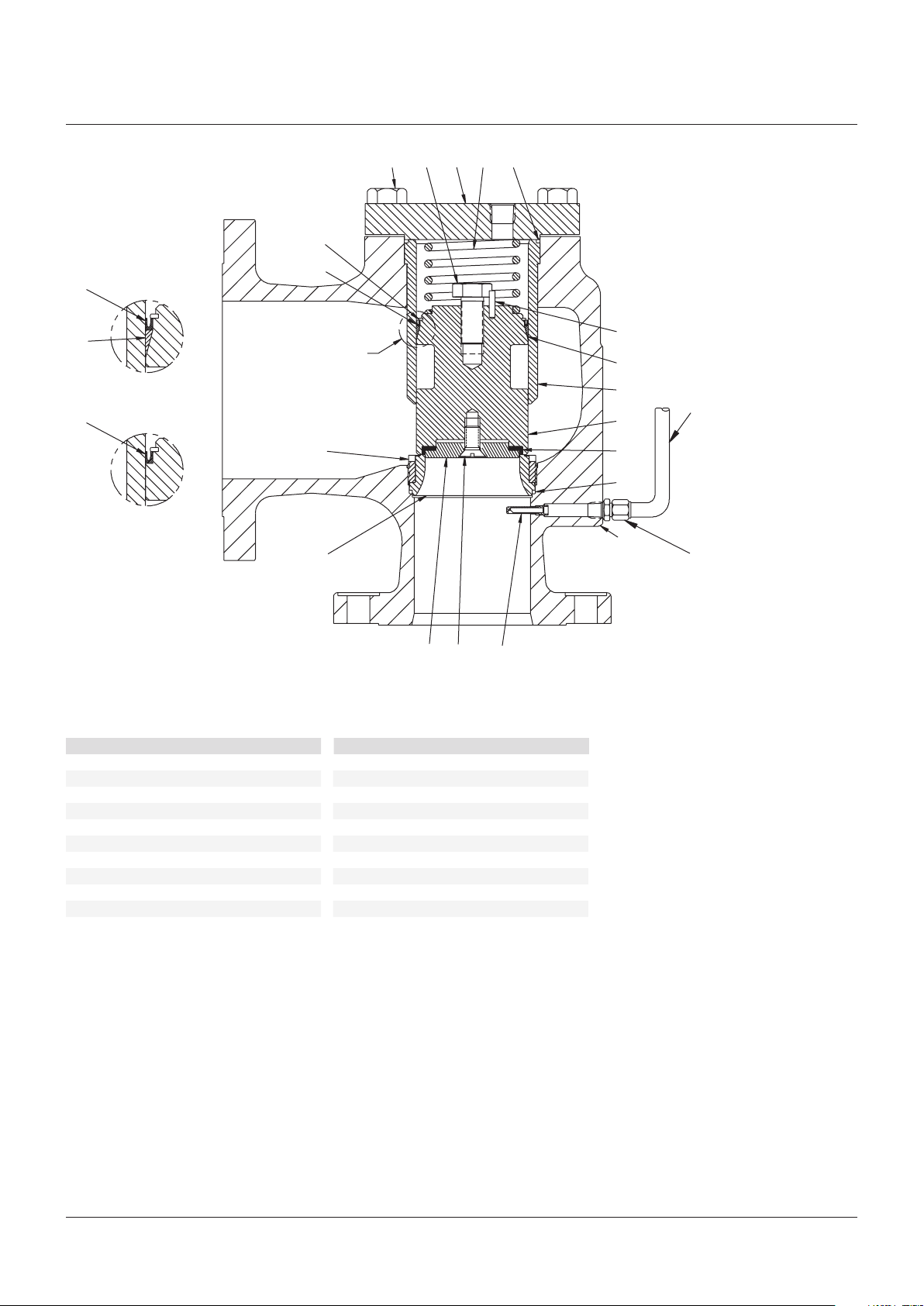
PARTS LIST
Item No. Part name
1 Body
2 Nozzle seal
3 Nozzle
4 Dipper tube
5 Liner
6 Liner seal
7 Seat
8 Seat retainer
9 Seat retainer screw
10 Piston
11 Lift adjusting bolt
12 Lock pin
13 Piston seal
15 Nozzle retainer
16 Dome spring
17 Cap
18 Cap bolt
21 Supply tube
22 Tube connector
23 Wedge ring
NOTES
[1]
Field replaceable only if required.
[2]
Recommended spare parts for repair.
[3]
Used only for liquid service.
[4]
Not used on 6”, 8” Type 443/453 and 4” and larger
Type 463.
Refer to Section 7.1 for soft goods repair kit part
numbers.
[1]
[1]
[2]
[2]
[4]
[4]
[2]
[3]
13
23
Detail A
Liquid service
13
Detail A
Gas service
FIGURE 1A - MAIN VALVE
443/453/463
See detail A
1
6
18 17
11
16 12
13
10
5
7
15
21
3
8
9
2
4
22
4
ANDERSON GREENWOOD SERIES 400 PISTON PILOT POPRV
InstallatIon and MaIntenance InstructIons
16
618 1711
14
13
13
23
Detail A
With wedge ring
13
Detail A
Without wedge ring
FIGURE 1B - MAIN VALVE
449/459/469
PARTS LIST
Item no. Part name
1 Body
2 Nozzle seal
3 Nozzle
4 Dipper tube
5 Liner
6 Liner seal
7 Seat
8 Seat retainer
9 Seat retainer screw
10 Piston
11 Lift adjusting bolt
[1]
[1]
[2]
[2]
12
See detail A
23
5
21
10
15
7
2
1
3
Item no. Part name
12 Lock pin
13 Piston seal
14 Snap ring
15 Nozzle retainer
16 Dome spring
17 Cap
18 Cap bolt
8
[4]
[2]
[2]
9 4
NOTES
[1]
Field replaceable only if required.
[2]
Recommended spare parts for repair.
[3]
Used 1” / 1½” (D,E,F orif. liq.only), 2” (liq. only),
and4” and larger Type 449/459 and 1½” (liq. only),
and 3” and larger type 469.
[4]
Not used on 6” or 8” Type 449/459 and 4”
andlarger Type 469.
22
21 Supply tube
22 Tube connector
[4]
23 Wedge ring
[3]
Refer to Section 7.1 for soft goods repair kit part
numbers.
5
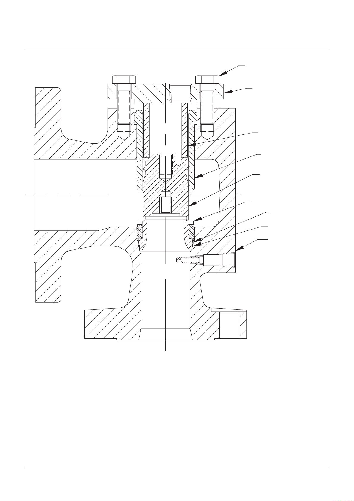
ANDERSON GREENWOOD SERIES 400 PISTON PILOT POPRV
InstallatIon and MaIntenance InstructIons
Cap bolt
Cap
Spacer
Liner
Piston
Nozzle retainer
FIGURE 2
Nozzle
Nozzle seal
Body
6

ANDERSON GREENWOOD SERIES 400 PISTON PILOT POPRV
InstallatIon and MaIntenance InstructIons
3 PILOT MAINTENANCE
Refer to Figures 3, 4, and 5.
Arrange all parts in an orderly sequence on
a flat work surface during disassembly. This
will facilitate assembly and help ensure that
the correct parts are assembled in the proper
sequence.
3.1 Disassembly
Before beginning disassembly, bleed off any
pressure trapped in the main valve or pilot.
3.1.1 Standard pilot – gas or liquid service
NOTE
If the pilot is equipped with a lift lever, the lift lever
handle assembly (Item 42) must be removed from the
cap (Item 17) before continuing with disassembly. To
do this, hold the lift lever handle in the position shown
in Figure 3, unscrew the handle assembly bushing
(Item 43) from the cap, and remove the handle
assembly.
Remove the cap (Item 17), for pilot with lift
lever remove jam nut (Item 44) and lift lever
nut (Item45), loosen the jam nut (Item 16),
and turn the adjustment screw (Item 15)
counterclockwise to relieve the spring tension.
Exercise caution when removing the spring
bonnet (Item 14) from pilots set above 500 psig,
as spring tension is not completely relieved
until the bonnet is removed. Remove the spring
bonnet, spring (Item 6), and spring washers
(Item 13).
Lift the piston plate (Item 4) with internal parts
attached upward and remove from the body
(Item 1). Unscrew the piston nut (Item 9) from
the feedback piston (Item 3) and remove the
lock washer (Item 36). Disassemble the sense
piston (Item 10) and feedback piston from the
piston plate. Unscrew the inlet nozzle (Item 5)
from the feedback piston. Remove the spool
spring (Item 8) and inlet nozzle with the spool
from the feedback piston.
3.1.2 Iso-Dome pilot – gas service
NOTE
All Iso-Dome pilots are gas service pilots; however,
fully assembled valves with these pilots may be either
gas service valves or liquid services valves.
After bleeding off any pressure trapped in the
main valve or pilot, remove the pilot with the
regulator (Item 55) attached from the main
valve. Unscrew and remove bracket bolts
(Items 52) and bracket bolts (Items 53). Slide
the bracket (Item 49) outward approximately
1½” along the regulator cover spacer (Item 50).
11
Using an
/
16” wrench, unscrew the adapter
(Item 48) with regulator attached from the body
(Item 1). If necessary, slide the bracket farther
out along the cover spacer so that it does not
hit the body. Support the regulator during
this operation in order to avoid damaging the
adapter threads or the body threads. Loosen
set screw (Item 54) and remove regulator cover
cap (Item 51), regulator cover spaces (Item 50),
and bracket.
Continue pilot disassembly in accordance with
the procedures described in paragraph 3.1.1
except that the Iso-Dome pilot uses an adapter
in place of the body plug (Item 2) in a standard
pilot.
3.1.3 Iso-Sense pilot – gas or liquid service
The Iso-Sense pilot sectional drawing shown in
Figure 3 is presented for identification purposes
only. This is a special pilot assembly which may
incorporate non-standard components. Contact
Anderson Greenwood for replacement parts
and maintenance instructions for individual
pilots (serial number is required for complete
identification).
Remove the bias spring (Item 11) and body
plug (Item 2) from the body. Using a hex key
(Allen wrench) inserted through the bottom
of the body into the hex socket in the outlet
nozzle (Item 25), unscrew the outlet nozzle and
remove it through the top of the body. Note
that when viewed from the bottom of the body,
the hex key is turned clockwise to unscrew the
outlet nozzle.
7

ANDERSON GREENWOOD SERIES 400 PISTON PILOT POPRV
InstallatIon and MaIntenance InstructIons
3.1.4 Pilot variations and accessories
For pilot equipped with a one-piece spool, Figure3
Style A, remove the spool seal (Item28) and the
outlet seat (Item 30) from the spool (Item31; then
remove the spool from the inlet nozzle.
For pilot equipped with a three-piece spool,
Figure 3 Style E, unscrew the spool nut (Item39)
from the inner spool (Item 41), remove the
outer spool (Item 40) from the inlet nozzle and
remove the inner spool from the outer spool.
For pilot equipped with a field test accessory,
Figure 4, remove this accessory with the shuttle
from the body (Item 1). Disassemble the dome
connector from the field test body and remove
the spring, plunger, and shuttle.
For pilot equipped with a backflow preventer
and pilot exhaust backflow check valve, Figure5,
remove these accessories from main valve
dome port (backflow preventer) and the pilot
exhaust port (backflow check valve). Unscrew
the backflow preventer bushing from the body
and remove the shuttle. Unscrew the fitting
from the backflow check valve body and remove
the flow washer and ball.
Remove and discard all old seats, seals, and
O-rings before beginning assembly.
3.2 Assembly
3.2.1 Standard pilot – gas or liquid service
Assembly is done in the reverse order of
disassembly. Lightly lubricate all O-rings, all
sliding surfaces, screw threads and spring
washer pivot points with Dow Corning No. 33
Silicone grease or equivalent. Do not lubricate
the inlet seat (Item 7) or the outlet seat (Item 30).
For pilot with lift lever, do not install lift lever
handle assembly (Item 42) until final pilot
adjustment is completed, see paragraph 4.6.
3.2.2 Iso-Dome pilot – gas service
All Iso-Dome pilots are gas service pilots
(seeNote paragraph 3.1.2).
Assemble pilot in accordance with procedures
described in paragraph 3.2.1. Support the
regulator when threading the adapter (Item48)
with regulator attached into the body (Item1).
With an
11
/
16” wrench used to back-up the
adapter, the regulator may be rotated ± ¼ turn
about the adapter axis to align the bracket
(Item 49) mounting surfaces on the body and
the regulator bracket (Item 56).
If alignment can not be achieved with ± ¼ turn,
unthread the regulator from the adapter. Clean
the ¼ NPT threads on the adapter and in the
regulator outlet port and wrap the adapter
threads with several wraps of PTFE thread seal
tape. Screw the regulator onto the adapter and
tighten sufficiently to effect a thread seal and
alignment of the bracket mounting surfaces.
Loosen the two #10-24 socket head cap screws
in the regulator bracket so that the bracket can
slide along the outside of the regulator. Install
the bracket and hand tighten two bracket
bolts (Item 52) into the body. Hand tighten
two bracket bolts (Item 53) into the regulator
bracket and securely tighten the two #10-24
socket head cap screws into the regulator
bracket.
Securely tighten the four bracket bolts. Do not
install the regulator cover spacer and regulator
cover cap until final adjustment is completed,
see paragraph 4.3.
Pilot assembly and pretest
When assembling piston plate with attached
internal parts subassembly to body
subassembly, orient hole in plate to fit over the
length of damper bushing (Item 38) projecting
past the body face. Engage spool in outlet
nozzle and press gently until assembly drops
in place.
Pretest to verify proper feedback piston
function by depressing piston stack assembly
downward. The bias spring should return
the stack assembly to the upward position. If
the stack assembly does not return, identify
and correct source of malfunction before
completing assembly.
8
 Loading...