

Emerson Anderson Greenwood 5200, Anderson Greenwood 200, Anderson Greenwood 800, Anderson Greenwood 90, Anderson Greenwood 500 Operating And Safety Instructions Manual
...Page 1
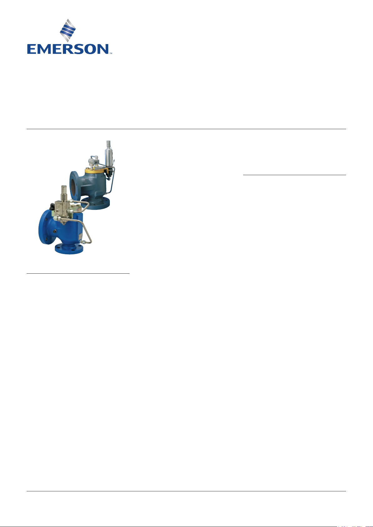
ANDERSON GREENWOOD PILOT OPERATED SAFETY RELIEF VALVES
Operating and Safety inStructiOnS
Before installation these instructions must be fully read and understood
TABLE OF CONTENTS
1. General ........................................................... 1
2. Storage and handling .................................... 2
3. Installation ..................................................... 2
4. Inlet piping ..................................................... 2
5. Discharge piping............................................ 2
6. Remote pressure pick-up ............................. 3
7. Set pressure verification testing .................. 4
SAFETY PRECAUTIONS
• When the safety valve is under pressure never
place any part of your body near the outlet of
the valve.
• The valve outlet and any separate drains should
be piped or vented to a safe location.
• Always wear proper safety gear to protect
hands, head, eyes, ears, etc. anytime you are
near pressurized valves.
• Never attempt to remove the safety valve from a
system that is pressurized.
•
Never make adjustments to or perform
maintenance on the safety valve while in
service unless the valve is isolated from the
system pressure. If not properly isolated from
the system pressure, the safety valve may
inadvertently open resulting in serious injury.
• Remove the safety valve prior to performing any
pressure testing of the system.
• The safety of lives and property often depends
on the proper operation of the safety valve.
The valve must be maintained according
to appropriate instructions and must be
periodically tested and reconditioned to ensure
correct function.
• For further information including adjustment,
maintenance, cleaning lapping and detail
illustrations obtain the appropriate Operation and
Maintenance Manual from the table on page 4.
These manuals may be requested from the factory
or are available at Emerson.com/FinalControl
WARNING
• If a gagging device is provided with the valve it
must be removed before the valve is put into
service.
• Removal of the seal wires in an attempt
to adjust and/or repair this product by
unauthorized or unqualified persons voids
the product warranty and may cause damage
to equipment and serious injury or death to
persons.
• This product is a safety related component
intended for use in critical applications.
The improper application, installation or
maintenance of the valve or the use of parts or
components not manufactured by Emerson may
result in a failure of thevalve.
• Any obstruction due to polymerization,
solidification or solid deposit will affect the
safety performance of this valve. Methods to
reduce such risk should be taken.
• A safety valve should be used only to protect a
system from overpressure during a pressure
upset. It should not be used as a control valve
that is required to operate continuously or as
a block valve to isolate portions of the system.
Itshould not be used as a pipe fitting or
transition piece in a piping system.
•
Any installation, maintenance, adjustment, repair
or test, performed on the safety valve must be
done in accordance with the requirements of all
applicable Emerson Procedures and Instructions
as well as applicable National and International
Codes and Standards.
• The information, specifications and technical
data (the ‘Specifications’) contained in this
document are subject to change without
notice. Emerson does not warrant that the
Specifications are current and assumes no
responsibility for the use or misuse thereof.
ThePurchaser should verify that there have been
no changes to the Specifications prior to use.
Service technicians are available to assist with
your installation or other field problems. Call
your nearest Emerson representative.
1 GENERAL
The intent of these instructions is to acquaint
the user with the storage, installation and
operation of this product.
This safety valve should only be used in
accordance with the applicable operating
instructions and within the application
specifications of the purchase order.
These valves have been tested and adjusted at
the factory. Contact the factory or a Emerson
authorized representative before making any
changes to the settings.
Engineering Doc. #05.9040.352 Rev. B
Emerson.com/FinalControl
© 2017 Emerson. All Rights Reserved.
VCOSI-06034-EN 18/01
Page 2

ANDERSON GREENWOOD PILOT OPERATED SAFETY RELIEF VALVES
Operating and Safety inStructiOnS
2 STORAGE AND HANDLING
Because cleanliness is essential to the
satisfactory operation and tightness of a safety
valve, precautions should be taken during
storage to keep out all foreign materials.
Inlet and outlet protectors should remain in
place until the valve is ready to be installed
in the system. Take care to keep the valve
inlet absolutely clean. It is recommended that
thevalve be stored indoors in the original
shipping container away from dirt and other
forms of contamination.
Safety valves must be handled carefully and
never subjected to shocks. Rough handling may
alter the pressure setting, deform valve parts
and adversely affect seat tightness and valve
performance.
The valve should never be lifted or handled
using the tubing, piping, pilot or pilot brackets.
When it is necessary to use a hoist, use the
lifting eye(s) on the main valve body. If there are
no lifting eyes a chain or sling should be placed
around the main valve body in a manner that
will ensure that the valve is in a vertical position
to facilitate installation.
3 INSTALLATION
Many valves are damaged when first placed
in service because of failure to clean the
connection properly when installed. Before
installation flange faces or threaded
connections on both the valve inlet and
the vessel and/or line on which the valve is
mounted must be thoroughly cleaned of all dirt
and foreign material.
Because foreign materials that pass into and
through safety valves can damage the valve,
the systems on which the valves are tested and
finally installed must also be inspected and
cleaned. New systems in particular are prone
to contain foreign objects that inadvertently get
trapped during construction and will destroy
the seating surface when the valve opens.
Thesystem should be thoroughly cleaned
before the safety valve is installed.
Foam padding is sometimes used to protect the
main valve seat during shipping. Check for any
foam padding inside the main valve and remove
before installation.
The gaskets used must be dimensionally
correct for the specific flanges. The inside
diameters must fully clear the safety valve inlet
and outlet openings so that the gasket does not
restrict flow.
For flanged valves, draw down all connection
studs or bolts evenly to avoid possible distortion
of the valve body.
The maximum torque for flange bolting for
valves with aluminum bodies should not exceed
the values shown in the following table.
Threaded valves have flats on the body inlet
neck to aid in installation. Use a back-up
wrench on the body outlet neck during the
installation of discharge piping.
Safety valves are intended to open and
close within a narrow pressure range. Valve
installations require accurate design both
as to inlet and discharge piping. Refer to
International, National and Industry Standards
for guidelines.
4 INLET PIPING
Connect this valve as direct and close as
possible to the vessel being protected.
The valve should be mounted vertically in an
upright position either directly on a nozzle from
the pressure vessel or on a short connection
fitting that provides a direct, unobstructed flow
between the vessel and the valve. Installing a
safety valve in other than this recommended
position will adversely affect its operation.
The valve should never be installed on a fitting
having a smaller inside diameter than the inlet
connection of the valve.
5 DISCHARGE PIPING
Discharge piping should be simple and direct.
A ‘broken’ connection near the valve outlet is
preferred wherever possible. All discharge
piping should be run as direct as is practicable
to the point of final release for disposal. The
valve must discharge to a safe disposal area.
The pilot exhaust is often vented to the
atmosphere under operating conditions,
since the discharge during operation is small.
When pilot discharge to the atmosphere is
not permissible, the pilot exhaust should
be connected either to the discharge piping
or through a supplementary piping system
to a safe location. When discharge piping is
designed, avoid the possibility of back pressure
on the pilot unless the pilot is a balanced
design.
Discharge piping must be drained properly
to prevent the accumulation of liquids on the
downstream side of the main valve or pilot.
The weight of the discharge piping should be
carried by a separate support and be properly
braced to withstand reactive thrust forces when
the valve relieves. The valve should also be
supported to withstand any swaying or system
vibrations.
ft·lb Nm
2 x 3 18 24
3 x 4 18 24
4 x 6 18 24
6 x 8 32 43
8 x 10 32 43
10 x 12 51 69
12 x 16 51 69
If the pilot valve is discharging into a
pressurized system be sure the valve is a
‘balanced’ design. Pressure on the discharge of
an ‘unbalanced’ design will adversely affect the
valve performance and set pressure.
Fittings or pipe having a smaller inside
diameter than the valve outlet connections
must not be used.
2
Page 3

ANDERSON GREENWOOD PILOT OPERATED SAFETY RELIEF VALVES
Operating and Safety inStructiOnS
6 REMOTE PRESSURE PICK-UP
When remote pressure sensing is specified, the
valve will have a red plastic plug with a warning
tag installed in the pilot pressure sensing
port. The tag reads ‘WARNING: THIS VALVE IS
EQUIPPED FOR INSTALLATION WITH REMOTE
PRESSURE PICK-UP’. Remove the plug and
connect the remote sense line to this port.
Remote pressure pick-up piping must be
installed in accordance with the following
requirements:
For Series 200, 400, 800, 5100 and 5200 valves
Remote pressure pick-up piping up to 100 feet
(30 m) in length must have an inside diameter
not less than 0.245” (6 mm), the inside diameter
of ⅜” x 0.065” wall (10 mm x 2 mm wall)
seamless tubing. For lengths greater than
100feet (30 m), larger tubing or pipe should be
used.
For Series 90, 500, and 900 valves
Remote pressure pick-up piping up to 20 feet
(6m) in length must have an inside diameter not
less than 0.430” (10 mm), the inside
½” x 0.035” wall (12 mm x 1 mmwall)
tubing. For lengths greater than 20feet (6 m),
larger tubing or pipe should be used.
diameter of
seamless
For Series 9000 valves
(Remote pressure pick-up is standard on all
vacuum and combination valves.)
For 6” (150 mm) and smaller valves, remote
pressure pick-up piping up to 20 feet (6 m) in
length must have an inside diameter not less
than 0.430” (10 mm), the inside diameter of ½”
x 0.035” wall (12 mm x 1 mm wall) seamless
tubing. For lengths greater than 20 feet (6 m),
larger tubing or pipe should be used.
For 8” (200 mm) and larger valves, remote
pressure pick-up piping for lengths up to
20feet (6 m) must have an inside diameter not
less than 0.824” (20.9 mm), the inside diameter
of ¾” schedule 40 pipe. For lengths greater
than 20 feet (6 m), larger pipe should be used.
Ensure that the pilot sensing port is within the
system protected by the main valve.
A block valve for shut off in the remote pilot sense
line is not recommended. A closed block valve
in the remote sense line renders the safety valve
inoperative. If one is used, it must be opened
before pressurizing the system or opening the
isolating block valve under the main valve.
For Series 700 valves
Remote pressure pick-up piping up to 10 feet
(3m) in length must have an inside diameter not
less than 0.245” (6 mm), the inside diameter
⅜” x 0.065” wall (10 mm x 2 mm wall) seamless
tubing. For lengths greater than 10 feet (6 m),
1” (25 mm) or larger pipe should be used. The
remote sense line must be self draining and
insulated to minimize condensate formation and
freezing potential.
of
3
Page 4

ANDERSON GREENWOOD PILOT OPERATED SAFETY RELIEF VALVES
Operating and Safety inStructiOnS
7 SET PRESSURE VERIFICATION TESTING
Set pressure verification testing should be performed in accordance with instructions in the
applicable Operation and Maintenance Manual.
OPERATION AND MAINTENANCE MANUALS
Valve model Operation and maintenance manual
Series 200 05.9040.268 (VCIOM-06018)
Series 400 with diaphragm pilot 05.9040.269 (VCIOM-06019)
Series 400 with piston pilot 05.9040.270 (VCIOM-06020)
Series 500 05.9040.272 (VCIOM-06022)
Series 800 05.9040.271 (VCIOM-06021)
Series 900 05.9040.273 (VCIOM-03377)
Series 727 - steam service 05.9040.192 (VCIOM-06013)
Series 727 - air/gas service 05.9040.238 (VCIOM-03096)
Series 93 (Series 90) 05.9040.081 (VCIOM-03092)
Series 93T (Series 90) 05.9040.082 (VCIOM-03093)
Series 91/94 (Series 90) 05.9040.080 (VCIOM-06025)
Series 95 (Series 90) 05.9040.083 (VCIOM-06026)
Series 9240 05.9040.171 (VCIOM-03091)
Series 9290 05.9040.174 (VCIOM-06012)
Series 9300 05.9040.275 (VCIOM-06024)
Series 9390 (Series 9300) for chloride service 05.9040.233
LCP 05.9040.313
MLCP 05.9040.324 (VCIOM-03101)
Series 5100 05.9040.349 (VCIOM-06040)
Series 5200 05.9040.370 (VCIOM-02850)
Neither Emerson, Emerson Automation Solutions, nor any of their affiliated entities assumes responsibility for the selection, use or maintenance of any product.
Responsibility for proper selection, use, and maintenance of any product remains solely with the purchaser and end user.
Anderson Greenwood is a mark owned by one of the companies in the Emerson Automation Solutions business unit of Emerson Electric Co. Emerson Automation
Solutions, Emerson and the Emerson logo are trademarks and service marks of Emerson Electric Co. All other marks are the property of their respective owners.
The contents of this publication are presented for informational purposes only, and while every effort has been made to ensure their accuracy, they are not to be
construed as warranties or guarantees, express or implied, regarding the products or services described herein or their use or applicability. All sales are governed by
our terms and conditions, which are available upon request. We reserve the right to modify or improve the designs or specifications of such products at any time without
notice.
Emerson.com/FinalControl
4
 Loading...