

Page 1

Information furnished by EMERSON Motion Control is believed to be accurate and
reliable. However, no responsibility is assumed by EMERSON Motion Control for its use.
EMERSON Motion Control reserves the right to change the design or operation of the
equipment described herein and any associated motion products without notice.
EMERSON Motion Control also assumes no responsibility for any errors that may appear
in this document. Information in this document is subject to change without notice.
P/N 400514-01
Rev.: A2
Date: October 22, 1999
© 1999 EMERSON Motion Control. All rights reserved.
ALP-130 and ALP-430
Auxiliary Logic Power Supply
Installation Manual
Page 2

ii
© 1999 EMERSON Motion Control. All rights reserved.
Part Number: 400514-01
Revision: A2
Date: October 1999
Printed in United States of America
Information in this document is subject to change without notice.
Companies, names, and data used in examples herein are fictitious
unless otherwise noted. No part of this document may be reproduced or
transmitted in any form or by any means, electronic or mechanical, for
any purpose, without the express written permission of EMERSON
Motion Control.
The following are trademarks of EMERSON Motion Control and may
not be reproduced in any fashion without written approval of
EMERSON Motion Control.
Microsoft, Excel and Windows are registered trademarks of Microsoft Corporation.
IBM is a registered trademark of International Business Machines, Inc.
Modbus is a trademark of Modicon, Inc.
Data Highway Plus is a trademark of Allen-Bradley
Schaffner is a trademark of Schaffner
Commercial names of products from other manufacturers or developers
that appear in this manual are registered or unregistered trademarks
of those respective manufacturers or developers, which have expressed
neither approval nor disapproval of EMERSON Motion Control.
This document has been prepared to conform to the current released version of the
hardware and software system. Because of our extensive development efforts and our
desire to further improve and enhance the product, inconsistencies may exist between the
product and documentation in some instances. Call your customer support representative if
you encounter an inconsistency.
Page 3

iii
Customer Service
EMERSON Motion Control
12005 Technology Drive
Eden Prairie, Minnesota 55344-3620
U.S.A.
Telephone: (612) 995-8000 or (800) 397-3786
It is EMERSON Motion Control’s goal to ensure your greatest
possible satisfaction with the operation of our products. We are
dedicated to providing fast, friendly, and accurate assistance.
That is why we offer you so many ways to get the support you
need. Whether it’s by phone, fax or modem, you can access
EMERSON Motion Control support information 24 hours a
day, seven days a week. Our wide range of services include:
FAX (612) 995-8011
You can FAX questions and comments to EMERSON Motion
Control. Just send a FAX to the number listed above.
Website and Email www.emersonmotioncontrol.com
Website: www.emersonmotioncontrol.com
Email: info@emersonmotioncontrol.com
If you have Internet capabilities, you also have access to
technical support using our website. The website includes
technical notes, frequently asked questions, release notes and
other technical documentation. This direct technical support
connection lets you request assistance and exchange software
files electronically.
Page 4

iv
ALP-130 and ALP-430 Auxiliary Logic Power Supply Installation Manual
Technical Service (612) 995-8033
Email: service@emersonmotioncontrol.com
EMERSON Motion Control’s products are backed by a team of
professionals who will service your installation wherever it
may be. Our technical service center in Minneapolis,
Minnesota is ready to help you solve those occasional problems
over the telephone. Our technical service center is available 24
hours a day for emergency service to help speed any problem
solving. Also, all hardware replacement parts, should they ever
be needed, are available through our service organization.
When you call, please be at your computer, have your
documentation in hand, and be prepared to provide the
following information:
• Product version number, found by choosing About from the
Help menu.
• The type of controller or product you are using.
• Exact wording of any messages that appear on your screen.
• What you were doing when the problem occurred.
• How you tried to solve the problem.
Need on-site help? EMERSON Motion Control provides
service, in most cases, the next day. Just call EMERSON’s
technical service center when on-site service or maintenance is
required.
Training Services (612) 995-8000
Email: training@emersonmotioncontrol.com
EMERSON Motion Control maintains a highly trained staff of
instructors to familiarize customers with EMERSON Motion
Page 5

v
Control’s products and their applications. A number of courses
are offered, many of which can be taught in your plant upon
request.
Application Engineering (612) 995-8003
Email: applengr@emersonmotioncontrol.com
An experienced staff of factory application engineers provides
complete customer support for tough or complex applications.
Our engineers offer you a broad base of experience and
knowledge of electronic motion control applications.
Customer Service (Sales) (612) 995-8000
Email: sales@emersonmotioncontrol.com
Authorized EMERSON Motion Control distributors may place
orders directly with our Order Processing Department by
calling the number listed above. For information on your local
distributor, call EMERSON Motion Control.
Document Conventions
Manual conventions have been established to help you learn to
use this manual quickly and easily. As much as possible, these
conventions correspond to those found in other Microsoft
Windows documentation.
Menu names and options are printed in bold type: the File
menu.
Dialog box names begin with uppercase letters: the Axis Limits
dialog box.
Dialog box field names are in quotes: “Field Name”.
Page 6
vi
ALP-130 and ALP-430 Auxiliary Logic Power Supply Installation Manual
Button names are in italic: OK button.
Source code is printed in Courier font: Case ERMS.
In addition, you will find the following typographic conventions
throughout this manual.
Safety Instructions
General Warning
Failure to follow safe installation guidelines can cause death or
serious injury. The voltages used in the product can cause
severe electric shock and/or burns, and could be
lethal.Extreme care is necessary at all times when working
with or adjacent to it. The installation must comply with all
relevant safety legislation in the country of use.
Qualified Person
For the purpose of this manual and product, a “qualified
person” is one who is familiar with the installation,
construction and operation of the equipment and the hazards
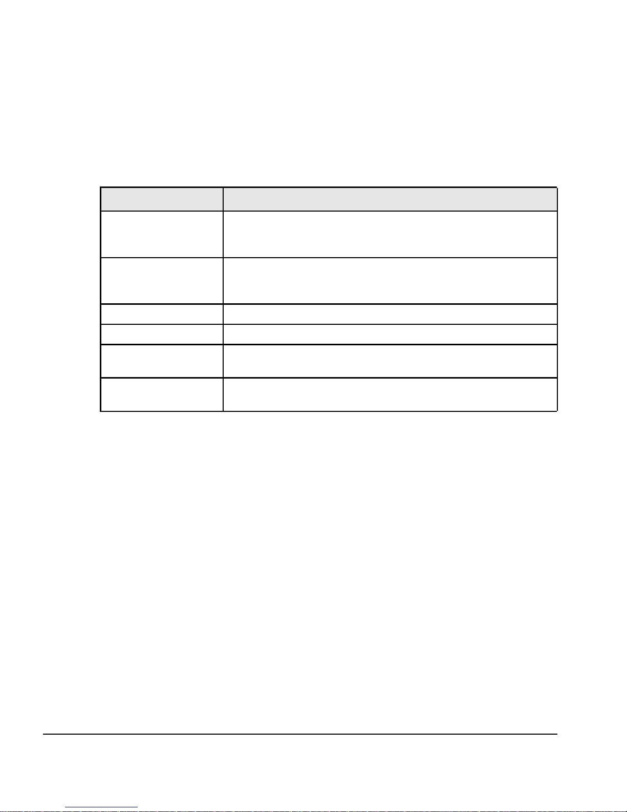
This Represents
bold
Characters that you must type exactly as they appear. For
example, if you are directed to type a:setup, you should type
all the bold characters exactly as they are printed.
italic
Place holders for information you must provide. For example, if
you are directed to type filename, you should type the actual
name for a file instead of the word shown in italic type.
ALL CAPITALS Directory names, file names, key names, and acronyms.
SMALL CAPS Non-printable ASCII control characters.
KEY1+KEY2
example: (Alt+F)
A plus sign (+) between key names means to press and hold
down the first key while you press the second key.
KEY1,KEY2
example: (Alt,F)
A comma (,) between key names means to press and release the
keys one after the other.
Page 7
vii
involved. In addition, this individual has the following
qualifications:
• Is trained and authorized to energize, de-energize, clear,
ground and tag circuits and equipment in accordance with
established safety practices.
• Is trained in the proper care and use of protective
equipment in accordance with established safety practices.
• Is trained in rendering first aid.
Warning
For the purpose of this manual and product, “Warning”
indicates death, severe personal injury or substantial
damage CAN result if proper precautions are not taken.
Caution
For the purpose of this manual and product, “Caution”
indicates minor personal injury or property damage CAN
result if proper precautions are not taken.
Note
For the purpose of this manual and product, “Note”
indicates information about the product or the respective
part of the manual which is essential to highlight.
Epsilon Only
For the purpose of this manual and product, the “Epsilon”
symbol indicates information about the Epsilon drive
specifically.
Page 8

viii
ALP-130 and ALP-430 Auxiliary Logic Power Supply Installation Manual
E Series Only
E
N
For the purpose of this manual and product, the “EN”
symbol indicates information about the E Series drive
specifically.
Throughout this manual, the word "drive" refers to an Epsilon
or E Series drive.
Page 9

ix
Underwriters Laboratories Listed
The ALP-130/-430 are marked with the “UL Listed” label after
passing a rigorous set of design and testing criteria developed
by UL (UL508C). This label indicates that the UL certifies this
product to be safe when installed according to the installation
guidelines and used within the product specifications.
The “conditions of acceptability” required by UL are:
• The ALP-130 ambient temperature must be 40° C (104° F)
or less.
• The ALP-430 ambient temperature must be 50° C (122° F)
or less.
CE Declaration of Conformity
The ALP-130/-430 (Auxiliary Logic Supply) is marked with the
“Conformite Europeenne Mark” (CE mark) after passing a
rigorous set of design and testing criteria. This label indicates
that this product meets safety standards when installed
according to the installation guidelines and used within the
product specifications.
LISTED 80XM
IND. CONT. EQ.
A
L
P
-
1
3
0
a
n
d
A
L
P
-
4
3
0
Page 10

x
ALP-130 and ALP-430 Installation Manual
Declaration of Conformity
Manufacturer’s Name:
EMERSON Motion Control
Manufacturer’s Address:
1365 Park Road
Chanhassen, MN 55317
USA
Declares that the following products:
Products Description:
Drive Accessories
Model Number:
RSR-2 and ALP-430
Conforms to the following product specification:
The products herewith comply with the requirements of the Low Voltage Directive (LVD) 73/23/EEC. These products are considered
components and as such, the EMC Directive (89/336/EEC) does not apply.
Supplementary information:
This electronic drive product is intended to be used with an appropriate motor, electrical protection components and other equipment to
form a complete end product or system. It must only be installed by a professional assembler who is familiar with requirements for safety
and electromagnetic compatibility (“EMC”). The assembler is responsible for ensuring that the end product or system complies with all the
relevant laws in the country where it is to be used. Refer to the product manual for installation guidelines.
August 18, 1999
Bradley Schwartz/ VP Engineering Date
European Contact:
Sobetra Automation
Langeveldpark Lot 10
P. Dasterleusstraat 2
1600 St. Pieters Leeuw, Belgium
Page 11

xi
Declaration of Conformity
Manufacturer’s Name:
EMERSON Motion Control
Manufacturer’s Address:
1365 Park Road
Chanhassen, MN 55317
USA
Declares that the following products:
Products Description:
E Series Digital Servo Drive
Model Number:
EN-204, EN-208 and EN-214
System Options:
This declaration covers the above products with the ALP-130 Backup Logic Power Supply and ECI-44
Screw Terminal Interface.
Conforms to the following product specification:
Electomagnetic Compatibility (EMC):
EN 55011/1991 Class A Group 1, CISPR 11/1990 Class A Group 1
EN 50082-2/1995: IEC 1000-4-2/1995; EN 61000-4-2, 4kV CD
IEC 1000-4-3/1995; EN 61000-4-3, ENV 50140/1993, 80% AM, 10V/m @ 3 m
IEC 1000-4-4/1995; EN 61000-4-4, 2 kV ALL LINES
IEC 1000-4-8/1993; EN 61000-4-8, 30 A/m
ENV 50141/1993, 80% AM, 10V, .15-80 MHz
ENV 50204/1995, Pulse, 900 MHz, 50% DTY, 200 Hz
Supplementary information:
The products herewith comply with the requirements of the Low Voltage Directive (LVD) 73/23/EEC and EMC Directive 89/336/EEC
This electronic drive product is intended to be used with an appropriate motor, electrical protection components and other equipment to form a complete end product or system.
It must only be installed by a professional assembler who is familiar with requirements for safety and electromagnetic compatibility (“EMC”). The assembler is responsible for
ensuring that the end product or system complies with all the relevant laws in the country where it is to be used. Refer to the product manual for installation guidelines.
December 2, 1997
Bradley Schwartz/ VP Engineering Date
European Contact:
Sobetra Automation
Langeveldpark Lot 10
P. Dasterleusstraat 2
1600 St. Pieters Leeuw, Belgium
Page 12

Page 13

xiii
Introduction
Auxiliary Power Supply . . . . . . . . . . . . . . . . . . . . . . . . . . . . . . . . 1
ALP-130 . . . . . . . . . . . . . . . . . . . . . . . . . . . . . . . . . . . . . . . . . . 1
ALP-430 . . . . . . . . . . . . . . . . . . . . . . . . . . . . . . . . . . . . . . . . . . 1
Installation
ALP-130 Wiring Example . . . . . . . . . . . . . . . . . . . . . . . . . . . . . . .3
ALP-430 Wiring Example . . . . . . . . . . . . . . . . . . . . . . . . . . . . . . .4
Installation Procedure . . . . . . . . . . . . . . . . . . . . . . . . . . . . . . . . . 5
ALPC-xxx Cable Installation Instructions . . . . . . . . . . . . . . . . . 7
Specifications
Power Supply Specifications. . . . . . . . . . . . . . . . . . . . . . . . . . . . . 9
ALP-130 Dimensions. . . . . . . . . . . . . . . . . . . . . . . . . . . . . . . . . . . 9
ALP-430 Dimensions. . . . . . . . . . . . . . . . . . . . . . . . . . . . . . . . . . 10
Table of Contents
A
L
P
-
1
3
0
a
n
d
A
L
P
-
4
3
0
Page 14

Page 15

1
Introduction
Auxiliary Power Supply
Note
ALP’s are intended for use with E Series drives only.
ALP-130
The ALP-130 supplies enough logic power for one E Series
drive with any function module (FM). It comes with the
hardware necessary for mounting to most DIN rail mounting
tracks and includes the screw terminal plug connectors to mate
with the auxiliary supply receptacle on the drive and the drive
end connector kit and includes a ALPC-xxx cable to mate with
the recepticle on the drive.
Note
The ALP-130 is considered a Class 2 device. As such, there
is not a connection for PE on the ALP-130. Protect Class 2
referes to any equipment in which protection against
electrical shock does not rely on basic insulation only, but in
which additonal safety precautions such as double
insulation or reinforced insulation are provided, there being
no provision for protective earthing or reliance upon
installation provisions according to EN 50178.
ALP-430
The ALP-430 has four isolated power supply outputs to provide
enough logic power for up to four E Series drives with function
modules. It comes with the hardware necessary for mounting
A
L
P
-
1
3
0
a
n
d
A
L
P
-
4
3
0
Page 16

2
ALP-130 and ALP-430 Installation Manual
to most mounting tracks or enclosures and includes the screw
terminal plug connectors to mate with the auxiliary supply
receptacle on the drives and the drive end connector kit and
includes four (4) ALPC-xxx cables to mate with the recepticle
on the drive.
Page 17

3
Installation
ALP-130 Wiring Example
230 VAC
Backup Power
ALPC-xxx Cable
A
L
P
-
1
3
0
a
n
d
A
L
P
-
4
3
0
Page 18

4
ALP-130 and ALP-430 Installation Manual
ALP-430 Wiring Example
230 VAC
Backup Power
ALPC-xxx
Cable
Page 19

5
Installation
Installation Procedure
Follow the wiring diagrams below for the ALP-130/-430
installation and fusing.
Use #16 to 18 AWG, 600V, insulated, stranded wire for AC in
and DC out wiring.
The ALP-130 and ALP-430 package includes the cable
assembly that mates with the 2-position header(s) on your
drive(s).
Figure 1: ALP-130 Connections and Internal Wiring
Diagram
Page 20

6
ALP-130 and ALP-430 Installation Manual
Figure 2: ALP-430 Connections and Internal Wiring
Diagram
Page 21

7
Installation
ALPC-xxx Cable Installation Instructions
The ALPC-xxx cable is designed to connect an auxiliary logic
power supply such as the ALP-130/430 to the E Series drive. It
includes a 2-position plug that mates with the 2-position
header (J3) on your E Series drive and flying leads that connect
to the auxiliary logic power supply.
Note
This manufactured cable must be used in order to maintain
the UL Listing on the drives and on the ALP-130/430 power
supplies.
Note
Refer to the “ALP-130 and ALP-430 Auxiliary Power Supply
Installation Manual” (P/N 400514-01) for power supply
installation instructions.
1. Break out the plastic knock-out tab in the J3 location on
the top of the drive.
2. Plug the connector end of the ALPC-xxx cable into the two
position receptacle in the J3 location.
3. route the cable to the power supply (i.e., ALP-130/430), cut
it to length, and connect the wires as shown below.
Red wire goes to +V
Black wire goes to -V
Page 22

8
ALP-130 and ALP-430 Installation Manual
Figure 1: Signal Description with the New Style Two Position
Receptacle in the J3 Location
All drives serial numbers 9747 and lower and some drive serial
number 9748 or higher, use a spring terminal for J3 rather
than a header. These drives will not use the ALPC-xxx cable.
See drawing below for connection descriptions for this type of
drive.
Figure 2: Signal Description with the Original Design
Spring Terminal in the J3 Location
Two position receptacle
The mating connector/cable assembly
ALPC-xxx plugs into the receptacle.
Additional cables available from
EMERSON Motion Control.
Page 23

9
Specifications
Power Supply Specifications
ALP-130 Dimensions
Model
Input Output IP
Rated
Ambient
Temperature
Weight
ALP-130
115/230 VAC
40 Watts
140 VDC
30 Watts
20 50° C (122° F)
1.6 lbs
(.07 kg)
ALP-430
115/230 VAC
130 Watts
140 VDC
(4) x 20 Watts
20 50° C (122° F)
7.7 lbs
(3.5 kg)
0.25
0.25
2.0 min.
2.0 min.
A
L
P
-
1
3
0
a
n
d
A
L
P
-
4
3
0
Page 24

10
ALP-130 and ALP-430 Installation Manual
ALP-430 Dimensions
6.53 0.18
2.25
7.05
7.50
0.23
2.95
0.35
0.22
2.0 min.
2.0 min.
0.25
0.25
 Loading...