

Emerson AL200 Owner's Manual
READ AND SAVE THESE INSTRUCTIONS
ACCESSORY
AL200
Ceiling Fan LED Accent
Light Fixture Owner's Manual
Net Weight: 0.43 Lbs.
Questions, problems, missing parts: Before returning to the store call
Emerson Electric Customer Service 8 a.m. - 6 p.m., Eastern, Monday-Friday
1-800-654-3545
www.emersonfans.com
Air Comfort Products
Part No. F40BP75400000 Form No. BP7540
Revision: 180123 U.L. Model No.: AL200
DIVISION OF EMERSON ELECTRIC CO.
8100 W. Florissant • St. Louis, MO63136

Table of Contents
Section Page
Safety Instructions . . . . . . . . . . . . . . . . . . . . . . . . . . . . . . . . . . . . . . . . . . . . . . . . . . . . . . . . . . . . . . . . . . . . . . . . . . . . . .2
1. Unpacking Instructions . . . . . . . . . . . . . . . . . . . . . . . . . . . . . . . . . . . . . . . . . . . . . . . . . . . . . . . . . . . . . . . . . . . . . . . . .3
2. Electrical Requirements . . . . . . . . . . . . . . . . . . . . . . . . . . . . . . . . . . . . . . . . . . . . . . . . . . . . . . . . . . . . . . . . . . . . . . .3
3. Installation on Ceiling Fan CF901 . . . . . . . . . . . . . . . . . . . . . . . . . . . . . . . . . . . . . . . . . . . . . . . . . . . . . . . . . . . . . . . . .4
4. Installation on Ceiling Fan CF921 . . . . . . . . . . . . . . . . . . . . . . . . . . . . . . . . . . . . . . . . . . . . . . . . . . . . . . . . . . . . . . .5-6
. Installation on Ceiling Fan CF5100 & CF5200 . . . . . . . . . . . . . . . . . . . . . . . . . . . . . . . . . . . . . . . . . . . . . . . . . . . . . . .7
5
Product Limited Warranty . . . . . . . . . . . . . . . . . . . . . . . . . . . . . . . . . . . . . . . . . . . . . . . . . . . . . . . . . . . . . . . . . . . . . . . . .8
READ AND SAVE THESE INSTRUCTIONS
Safety Instructions
WARNING
TO REDUCE THE RISK OF FIRE, ELECTRICAL SHOCK,
OR INJURY TO PERSONS, OBSERVE THE
FOLLOWING:
a. Use this unit only in a m anner intended by the
manufacturer. If you have questions, contact the
manufacturer.
b. Before servicing or cleaning unit, switch power off
at se r v i c e panel and lo c k service pa n e l
disconnecting means to prevent power from being
switched on a c c i d e n t a l l y . W h e n t h e s e r v i c e
disconnecting means cannot be locked, securely
fa sten a war ning de vice , s uch as a tag, to the
service panel.
1. Read your Owner’s Manual carefully before installing
the light fixture. Retain Owner’s Manual for future
reference.
2. Be car eful of the fan an d blades wh en c lean ing,
painting, or working near the fan. Before installing or
servicing the light fixture or ceiling fan, switch power
off at service pa n e l and lo c k service pa n e l
disconnecting means to prevent power from being
switched on accidentally. When t h e s e r v i c e
disconn ecting means cannot be lock ed, secu rely
fasten a warning device, such as a tag, to the service
panel.
!
Additional Safety Instructions for Installation
1. To avoid possible shock, be sure electricity is turned
off at the fuse box or circuit breaker before wiring.
2. All wiring must be in accordance with the National
El ectri c al C ode “ANSI /NFPA 70- 2014” and Loc a l
Electrical Codes. Use the National Electrical Code if
Local Codes do not exist. The ceiling fan must be
grounded as a precaution against possible electrical
sh ock. Ele ctri cal insta llat ion sho uld be mad e or
approved by a licensed electrician.
3. Make certain no bare wires are exposed outside the
wire connectors.
4. Follow the recommended instructions for the proper
method of wiring your new light fixture. If you do not
know enough about electrical wiring knowledge or
experience , h ave your li ght fixture in sta lled by a
licensed electrician. Any electrical work not described
in this manual should be performed by a licensed
electrician.
WARNING
To reduce the risk of possible fire and electrical shock,
install only on Emerson Models CF901, CF921, CF5100
& CF5200 Ceiling Fans.
This LED Accent Light Fixture is NOT to be used on
Emerson CF Series Ceiling Fans installed in damp or
wet locations.
!
Troubleshooting
TROUBLE PROBABLE CAUSE SUGGESTED REMEDY
LED Will Not Loose Electrical Connections. Shut off the Branch Circuit Electricity at the Fuse Box or Breaker Panel
Illuminate. and check the LED Accent Light Fixture Electrical Connectors for
proper Installation.
U.L. Model No.: AL200
2
B
A
1. Unpacking Instructions
WARNING
o not install or use accessory if any part is damaged
D
or missing. Call Toll-Free for replacement parts:
!
1-800-654-3545
WARNING
This product is designe d t o use on ly those part s
supplied with this product and/or any accessories
designated specifically for use with this product by
Emerson Electric Co. Substitution of parts or
accessories not designated for use with this product
by Emerson Electric Co. could result in personal injury
or property damage.
!
1.1
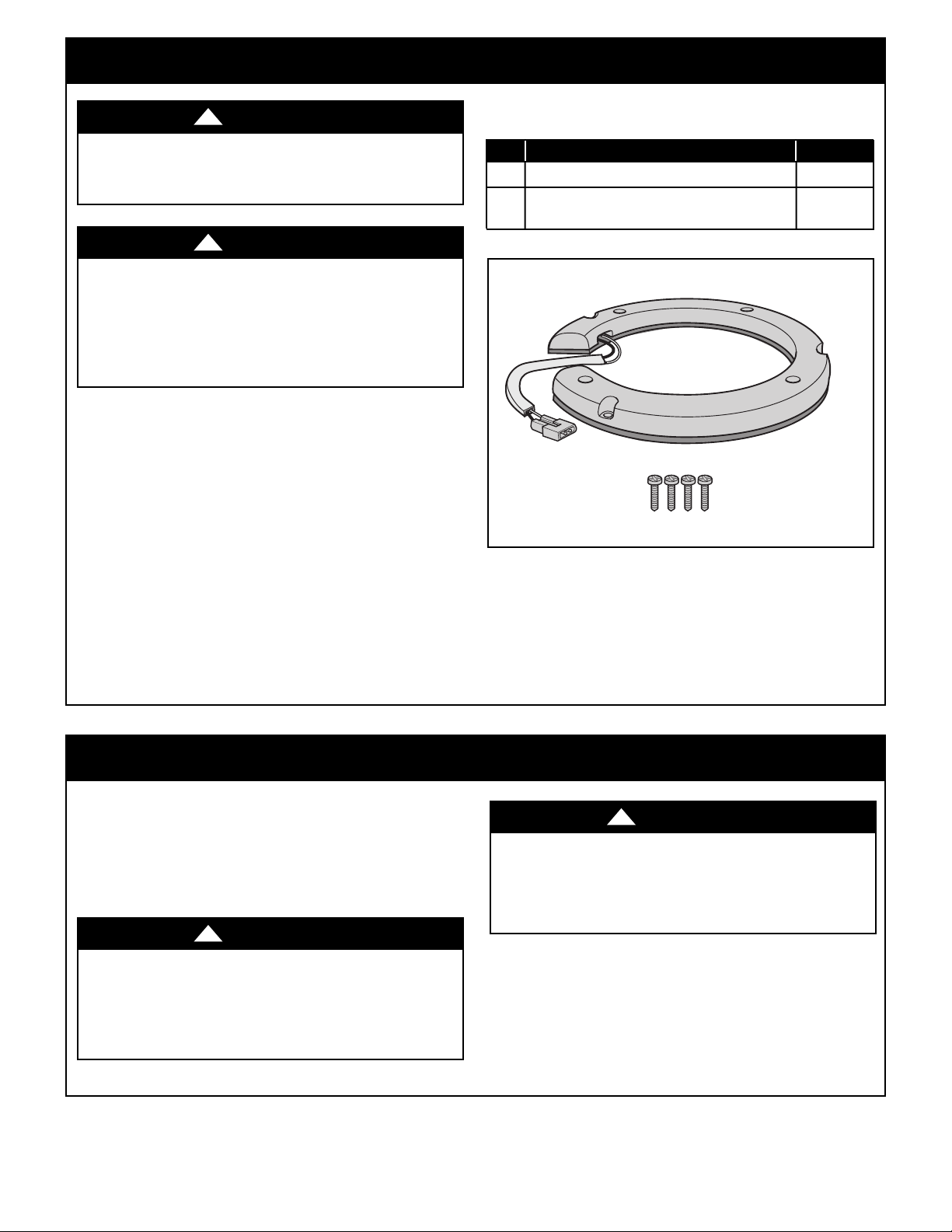
Check to see that you have received the following parts:
NOTE: If you are uncertain of part description, refer
to exploded view illustration.
NOTE: Place the parts from the hardware bags in a
small container to keep them from being lost.
If any p a r t s are mis s i n g, call 1 - 8 0 0-654-3 5 4 5
for replacement parts before proceeding.
TOOLS NEEDED FOR INSTALLATION
One Phillips Head Screwdriver One Stepladder
PACKAGE CONTENTS
Part Description Quantity
A LED Accent Light Fixture 1
B Loose Parts Bag Containing:
#8-32 Pan Head Screws (1 spare) 4
NOTE: Emer s o n Ce i l i ng Fa ns ha ve di fferent
configurations of how to assemble the AL200 LED
Accent Light Fixture to each fan housing. Locate
Your Ceiling Fan Model Number in this manuals and
proceed from there the Assembly of the AL200 LED
Accent Light Fixture.
2. Electrical Requirements
2.1
Disconnect electrical power to the branch circuit at the
Circuit Breaker or Main Fuse Box before attempting to
install t h e C e i l i n g Fan LED Accent L i g h t F i x t u r e
Accessory.
WARNING
Turning off wall swi tch is not sufficient . To avoid
possible electrical shock, be sure electricity is turned
off at the main fuse box before wiring. All wiring must
be in accordance with National and Local codes and
the ceilin g fan m u s t be p r o p erly g r o u n d e d as a
precaution against possible electrical shock.
!
WARNING
To avoid fire or shock, follow all wiring instructions
carefully.
Any e l e c t r i c a l work not d e s c r i b e d i n these
instructions should be done or approved by a licensed
electrician.
Please call Em e r son T echnical Support at
1- 800-654-354 5 if you have any question s abo ut
Installation and Operation of this Ceiling Fan LED
Accent Light Fixture Accessory.
3
!
emersonfans.com
Please contact 1-800-654-3545 for further assistance
U.L. Model No.: AL200

3. Installation for Ceiling Fan CF901
MOTOR
HOUSING
ASSEMBLY
LED ACCENT
LIGHT FIXTURE
MOTOR
HOUSING
ASSEMBLY
MALE 2-PIN
CONNECTOR
LIGHT FIXTURE
FEMALE 2-PIN
CONNECTOR
MOTOR
HOUSING
ASSEMBLY
HOLES (3)
#8-32 PAN HEAD
SCREWS (3)
LIGHT FIXTURE
MOUNTING
HOLES (3)
MOTOR HOUSING ASSEMBLY
MALE 2-PIN CONNECTOR
LIGHT FIXTURE
FEMALE 2-PIN
CONNECTOR
CONNECTOR
WIRE STORAGE
3.1
Position the LED Accent Light Fixture so that the
ownrod passes thro ugh the opening of the LED
D
Accent Light Fixture.
lign the LED Accent Light Fi xture Female 2-Pin
A
Connector with the Motor Housing Assembly Male
2-Pin Connector (Figure 1).
3.2
Align the Mounting Holes of the LED Accent Light
Fixture and the Motor Housing Assembly (Figure 2).
Figure 1
NOTE: Be s ure t h e L E D Ac c e n t Li g h t Fix t u r e
Connector is located close to the Motor Housing
Assembly Connector for ease of installation.
Install the LED Accent Light Fixture t o the Mot or
Housing Assembly using three #8-32 Pan Head Screws
(supplied) (Figure 2).
WARNING
To avoid possible fire or electric shock, be careful not
to pinch wires under the LED Accent Light Fixture
during assembly.
3.3
Securely engage the LED Accent Light Fixture Female
2-Pin Connector to the Motor Housing Assembly Male
2-Pin Connector (Figure 3).
For s t o r a g e of excess Con n e c t o r Wire, tuck the
Connector Wire along inside edge of the LED Accent
Light Fixture (Figure 3).
U.L. Model No.: AL200
!
Figure 2
Figure 3
4

4. Installation for Ceiling Fan CF921
M
OTOR HOUSING
A
SSEMBLY
COUPLER COVER
SCREWS (3)
(RETAIN FOR LATER
INSTALLATION)
COUPLER COVER
MOTOR
HOUSING
ASSEMBLY
#8-32 PAN HEAD
SCREWS (3)
LED ACCENT
LIGHT FIXTURE
LIGHT FIXTURE
MOUNTING
HOLES (3)
4.1
Remove the three Coupler Cover Screws and slide the
oupler Cover up the Downrod for installation of LED
C
Accent Light Fixture (Figure 4).
etain the three Screws for reinstallation of Coupler
R
Cover (Steps 4.4 & 4.5). (Figure 4).
4.2
Position the LED Accent Light Fixture so that the
Downrod passes thr ough the opening of the L ED
Accent Light Fixture (Figure 5).
Figure 4
Align the Mounting Holes of the LED Accent Light
Fixture to the Motor Housing Assembly (Figure 5).
NOTE: Be s ure t h e L E D Ac c e n t Li g h t Fix t u r e
Connector is located close to the Motor Housing
Assembly Connector for ease of installation.
Install the LED Accent Light Fixture t o the Mot or
Housing Assembly using the three #8-32 Pan Head
Screws (supplied) (Figure 5).
WARNING
To avoid possible fire or electric shock, be careful not
to pinch wires under the LED Accent Light Fixture
during assembly.
!
Figure 5
emersonfans.com
Please contact 1-800-654-3545 for further assistance
5
U.L. Model No.: AL200
 Loading...