

Page 1

Instruction Manual
IM-106-400 IMPS, Rev. 2.0
February 2009
IMPS 4000
Intelligent Multiprobe
Test Gas Sequencer
http://www.raihome.com
Page 2

Page 3

HIGHLIGHTS OF CHANGES
Effective February 28, 2009 - Rev. 2.0
Page Summary
General Reformatted entire manual in accordance with Emerson Process Management style and
format requirements. Changed all general references to Oxymitter to read oxygen
transmitter. Changed specific references to Oxymitter 4000 to include X-STREAM O
Transmitter. Revised illustrations to meet Emerson Process Management format
requirements and to show updated Rosemount Analytical product logo where applicable.
Cover Updated photo, revision number and release date.
Page i and ii Added Essential Instructions section with Technical Support Hotline information.
1-1 Revised text of NOTE.
1-4 Revised Figure 1-3 to include electrical and pneumatic diagram connections from IMPS
to X-STREAM probe housing and Xi unit.
2-4 Revised Electrical Connections discussion to include separate steps for Oxymitter and
X-STREAM. Changed all OXT terminal indicators to read XMTR.
2-5 Revised Figure 2-3 to include X-STREAM Xi unit connection and setup data.
3-6 and 3-7 Revised Automatic Calibration instructions to include expanded autocalibration setup
details for Oxymitter and new setup details for X-STREAM.
3-7 Added Xi Keypad paragraph to Semi-Automatic Calibration instructions.
A-1 Added new Appendix A , Safety Data.
B-1 Added new Appendix B, Return of Material.
I-1 Added new Index.
Back Cover Updated company addresses.
2
Page 4

Page 5

Instruction Manual
IM-106-880, Rev 2.0
February 2009
IMPS 4000
Table of Contents
Essential Instructions. . . . . . . . . . . . . . . . . . . . . . . . . . . . . . . . . . . . . . . . i
Preface . . . . . . . . . . . . . . . . . . . . . . . . . . . . . . . . . . . . . . . . . . . . . . . . . . ii
Definitions . . . . . . . . . . . . . . . . . . . . . . . . . . . . . . . . . . . . . . . . . . . . . . . . ii
Symbols. . . . . . . . . . . . . . . . . . . . . . . . . . . . . . . . . . . . . . . . . . . . . . . . . . ii
Technical Support Hotline . . . . . . . . . . . . . . . . . . . . . . . . . . . . . . . . . . . . ii
SECTION 1
Description and
Specifications
SECTION 2
Installation
SECTION 3
Operation
Introduction . . . . . . . . . . . . . . . . . . . . . . . . . . . . . . . . . . . . . . . . . . . . . 1-1
Component Checklist. . . . . . . . . . . . . . . . . . . . . . . . . . . . . . . . . . . . . . 1-2
System Overview. . . . . . . . . . . . . . . . . . . . . . . . . . . . . . . . . . . . . . . . . 1-2
Physical Description . . . . . . . . . . . . . . . . . . . . . . . . . . . . . . . . . . . . 1-2
Theory of Operation. . . . . . . . . . . . . . . . . . . . . . . . . . . . . . . . . . . . . . . 1-4
Z-Purge Option . . . . . . . . . . . . . . . . . . . . . . . . . . . . . . . . . . . . . . . . . . 1-5
Specifications. . . . . . . . . . . . . . . . . . . . . . . . . . . . . . . . . . . . . . . . . . . . 1-5
Overview . . . . . . . . . . . . . . . . . . . . . . . . . . . . . . . . . . . . . . . . . . . . . . . 2-1
Mechanical Installation . . . . . . . . . . . . . . . . . . . . . . . . . . . . . . . . . . . . 2-1
Gas Connections . . . . . . . . . . . . . . . . . . . . . . . . . . . . . . . . . . . . . . . . . 2-3
Electrical Connections . . . . . . . . . . . . . . . . . . . . . . . . . . . . . . . . . . . . . 2-3
Switch Settings . . . . . . . . . . . . . . . . . . . . . . . . . . . . . . . . . . . . . . . . . . 2-5
Overview . . . . . . . . . . . . . . . . . . . . . . . . . . . . . . . . . . . . . . . . . . . . . . . 3-1
Calibration Requirements . . . . . . . . . . . . . . . . . . . . . . . . . . . . . . . . . . 3-1
Operator Interface Description. . . . . . . . . . . . . . . . . . . . . . . . . . . . . . 3-2
Membrane Keypad . . . . . . . . . . . . . . . . . . . . . . . . . . . . . . . . . . . . . 3-3
LCD Display . . . . . . . . . . . . . . . . . . . . . . . . . . . . . . . . . . . . . . . . . . 3-3
Using The Operator Interface . . . . . . . . . . . . . . . . . . . . . . . . . . . . . . 3-5
Selecting a Parameter . . . . . . . . . . . . . . . . . . . . . . . . . . . . . . . . . . 3-5
Changing a Typical Parameter . . . . . . . . . . . . . . . . . . . . . . . . . . . . 3-5
Test Gas Flow Setup . . . . . . . . . . . . . . . . . . . . . . . . . . . . . . . . . . . . . . 3-6
Automatic Calibration. . . . . . . . . . . . . . . . . . . . . . . . . . . . . . . . . . . . . . 3-6
Semi-Automatic Calibration . . . . . . . . . . . . . . . . . . . . . . . . . . . . . . . . 3-7
SECTION 4
Troubleshooting
http://www..raihome.com
Overview . . . . . . . . . . . . . . . . . . . . . . . . . . . . . . . . . . . . . . . . . . . . . . . 4-1
Troubleshooting. . . . . . . . . . . . . . . . . . . . . . . . . . . . . . . . . . . . . . . . . . 4-1
Calibration Troubleshooting. . . . . . . . . . . . . . . . . . . . . . . . . . . . . . . . . 4-3
PLC I/O LED Indications . . . . . . . . . . . . . . . . . . . . . . . . . . . . . . . . . . . 4-4
Page 6

IMPS 4000
Instruction Manual
IM-106-4000 IMPS, Rev 2.0
February 2009
SECTION 5
Maintenance and Service
SECTION 6
Replacement Parts
APPENDIX A
Safety Data
APPENDIX B
Return of Material
Overview . . . . . . . . . . . . . . . . . . . . . . . . . . . . . . . . . . . . . . . . . . . . . . . 5-1
Fuse Replacement. . . . . . . . . . . . . . . . . . . . . . . . . . . . . . . . . . . . . . . . 5-3
PLC Replacement . . . . . . . . . . . . . . . . . . . . . . . . . . . . . . . . . . . . . . . . 5-3
Operator Interface Replacement . . . . . . . . . . . . . . . . . . . . . . . . . . . . . 5-5
Solenoid Replacement. . . . . . . . . . . . . . . . . . . . . . . . . . . . . . . . . . . . . 5-5
Pressure Regulator Maintenance . . . . . . . . . . . . . . . . . . . . . . . . . . . 5-6
Pressure Adjustments . . . . . . . . . . . . . . . . . . . . . . . . . . . . . . . . . . 5-6
Condensation Drain . . . . . . . . . . . . . . . . . . . . . . . . . . . . . . . . . . . . 5-6
Flowmeter Adjustments . . . . . . . . . . . . . . . . . . . . . . . . . . . . . . . . . . . . 5-6
Reference Gas Flowmeter . . . . . . . . . . . . . . . . . . . . . . . . . . . . . . . 5-6
Test Gas Flowmeter . . . . . . . . . . . . . . . . . . . . . . . . . . . . . . . . . . . . 5-6
Replacement Parts List . . . . . . . . . . . . . . . . . . . . . . . . . . . . . . . . . . . . 6-1
Safety Instructions . . . . . . . . . . . . . . . . . . . . . . . . . . . . . . . . . . . . . . . . A-2
Returning Material . . . . . . . . . . . . . . . . . . . . . . . . . . . . . . . . . . . . . . . . B-1
TOC-2
Page 7

Instruction Manual
IM-106-400 IMPS, Rev. 2.0
February 2009
Intelligent Mutiprobe Test Gas Sequencer
4000 IMPS
READ THIS PAGE BEFORE PROCEEDING!
ESSENTIAL
INSTRUCTIONS
Emerson Process Management designs, manufactures and tests its products
to meet many national and international standards. Because these
instruments are sophisticated technical products, you MUST properly
install, use, and maintain them to ensure they continue to operate within
their normal specifications. The following instructions MUST be adhered to
and integrated into your safety program when installing, using, and
maintaining Emerson’s Rosemount Analytical products. Failure to follow the
proper instructions may cause any one of the following situations to occur:
Loss of life; personal injury; property damage; damage to this instrument; and
warranty invalidation.
• Read all instructions
product.
• If you do not understand any of the instructions, contact your
Emerson Process Management representative for clarification.
• Follow all warnings, cautions, and instructions
supplied with the product.
• Inform and educate your personnel
operation, and maintenance of the product.
• Install your equipment as specified in the Installation Instructions
of the appropriate Instruction Manual and per applicable local and
national codes. Connect all products to the proper electrical and
pressure sources.
• To ensure proper performance, use qualified personnel
operate, update, program, and maintain the product.
• When replacement parts are required, ensure that qualified people use
replacement parts specified by Emerson Process Management.
Unauthorized parts and procedures can affect the product's
performance, place the safe operation of your process at risk, and
VOID YOUR WARRANTY. Look-alike substitutions may result in fire,
electrical hazards, or improper operation.
• Ensure that all equipment doors are closed and protective covers
are in place, except when maintenance is being performed by
qualified persons, to prevent electrical shock and personal injury.
prior to installing, operating, and servicing the
marked on and
in the proper installation,
to install,
http://www.raihome.com
The information contained in this document is subject to change without
notice.
Page 8

Instruction Manual
IM-103-400A, Rev. 2.0
4000 IMPS
February 2009
PREFACE The purpose of this manual is to provide information concerning the
components, functions, installation and maintenance of the IMPS 4000
Intelligent Multiprobe Test Gas Sequencer.
DEFINITIONS The following definitions apply to WARNINGS, CAUTIONS, and NOTES
found throughout this publication.
Highlights an operation or maintenance procedure, practice, condition, statement, etc. If not
strictly observed, could result in injury, death, or long-term health hazards of personnel.
Highlights an operation or maintenance procedure, practice, condition, statement, etc. If not
strictly observed, could result in damage to or destruction of equipment, or loss of
effectiveness.
SYMBOLS
TECHNICAL SUPPORT
HOTLINE
NOTE
Highlights an essential operating procedure, condition, or statement.
:
EARTH (GROUND) TERMINAL
:
PROTECTIVE CONDUCT OR TERMINAL
:
RISK OF ELECTRICAL SHOCK
:
WARNING: REFER TO INSTRUCTION MANUAL
NOTE TO USERS
The number in the lower right corner of each illustration in this publication is a
manual illustration number. It is not a part number, and is not related to the
illustration in any technical manner.
For assistance with technical problems, please call the Customer Support
Center (CSC). The CSC is staffed 24 hours a day, 7 days a week.
Phone: 1-800-433-6076 1-440-914-1261
In addition to the CSC, you may also contact Field Watch. Field Watch
coordinates Emerson Process Management’s field service throughout the
U.S. and abroad.
Phone: 1-800-654-RSMT (1-800-654-7768)
Emerson Process Management may also be reached via the Internet through
e-mail and the World Wide Web:
e-mail: GAS.CSC@emerson.com
World Wide Web: www.raihome.com
ii
Page 9

Instruction Manual
IM-106-400 IMPS, Rev. 2.0
February 2009
4000 IMPS
Section 1 Description and Specifications
Introduction . . . . . . . . . . . . . . . . . . . . . . . . . . . . . . . . . . . . . page 1-1
Component Checklist . . . . . . . . . . . . . . . . . . . . . . . . . . . . . page 1-2
System Overview . . . . . . . . . . . . . . . . . . . . . . . . . . . . . . . . page 1-2
Theory of Operation . . . . . . . . . . . . . . . . . . . . . . . . . . . . . . page 1-4
Z-Purge Option . . . . . . . . . . . . . . . . . . . . . . . . . . . . . . . . . . page 1-5
Specifications . . . . . . . . . . . . . . . . . . . . . . . . . . . . . . . . . . . page 1-5
INTRODUCTION The Rosemount Analytical IMPS 4000 Intelligent Multiprobe Test Gas
Sequencer is used with the Oxymitter 4000 or the X-STREAM Oxygen
Transmitter. The IMPS 4000 has the intelligence to provide test gas
sequencing of up to four oxygen transmitters to accommodate automatic and
semi-automatic calibration routines. Table 1-1 lists the available IMPS 4000
versions.
Table 1-1. IMPS 4000 Versions
NOTE
The IMPS 4000 Intelligent Multiprobe Test Gas Sequencer operates the same
when used with the Oxymitter 4000 or the X-STREAM O
Transmitter with
2
HART or FOUNDATION fieldbus Communications. References to the
Oxymitter 4000 or the X-STREAM O
manual also include the Oxymitter 5000 and the X-STREAM O
Transmitter throughout this instruction
2
Transmitter
2
with FOUNDATION fieldbus Communications.
Part Number Description Number of O2 Transmitters
3D39695G01 IMPS 1
3D39695G02 IMPS 2
3D39695G03 IMPS 3
3D39695G04 IMPS 4
3D39695G05 IMPS w/115 V Heater 1
3D39695G06 IMPS w/115 V Heater 2
3D39695G07 IMPS w/115 V Heater 3
3D39695G08 IMPS w/115 V Heater 4
3D39695G09 IMPS w/220 V Heater 1
3D39695G10 IMPS w/220 V Heater 2
3D39695G11 IMPS w/220 V Heater 3
3D39695G12 IMPS w/220 V Heater 4
http://www.raihome.com
Page 10

4000 IMPS
Instruction Manual
IM-106-400 IMPS, Rev. 2.0
February 2009
COMPONENT
CHECKLIST
Figure 1-1. Typical System Package
A typical IMPS 4000 should contain the items shown in Figure 1-1. Record
the part number, serial number, and order number for the IMPS 4000 on the
back cover of this manual.
1. Instruction Manual
2. IMPS 4000
SYSTEM OVERVIEW
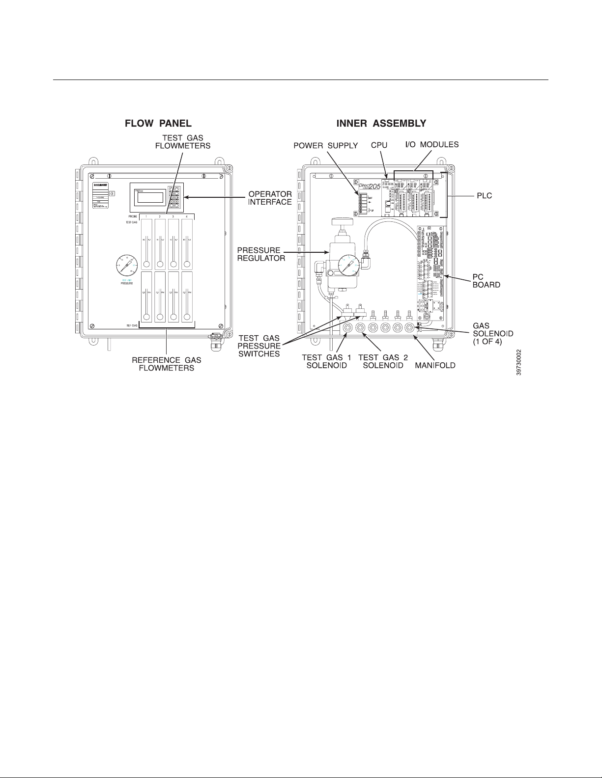
Physical Description The main components of the IMPS 4000 are housed in a NEMA 4X (IP56)
enclosure for use in non-hazardous areas.
The main internal components include the flow panel and the inner assembly.
Flow Panel (Figure 1-2)
The Programmable Logic Controller (PLC) operator interface and the
reference and test gas flowmeters are mounted to the flow panel.
1. The PLC operator interface allows you to set up time-sequenced
calibration routines for up to four oxygen transmitters. It also allows you
to initiate a semi-automatic calibration.
2. Four sets of test gas and reference gas flowmeters are mounted on the
flow panel. One set of flowmeters is available for each of the four
oxygen transmitters that can be attached to the IMPS 4000. The test
gas flowmeter indicates the amount of test gas sent to the oxygen
transmitter. The reference gas flowmeter indicates the amount of
reference air flowing to the oxygen transmitter.
1-2
Page 11
Instruction Manual
IM-106-400 IMPS, Rev. 2.0
February 2009
Figure 1-2. IMPS Components
4000 IMPS
Inner Assembly
The inner assembly consists of the PLC, PC board, pressure regulator, gas
solenoids, test gas pressure switches, and heater.
1. The PLC consists of a power supply, Central Processing Unit (CPU),
and three I/O modules.
a. The power supply supplies the voltage and current needed to
operate the IMPS 4000.
b. The CPU controls most system operations. It contains the program
memory in which the information entered into the PLC operator
interface is stored, and it processes the I/O signals received from the
I/O modules.
c. The I/O modules are terminated on the PC board. They receive and
send signals between the PLC and PC board for communication
between the oxygen transmitter and the IMPS 4000.
2. The PC board contains all wiring connections for up to four oxygen
transmitters.
3. The pressure regulator ensures the instrument air (reference gas)
flowing to the oxygen transmitter is at a constant pressure. The
regulator also has a drain valve that drains excess moisture from the
internal gas circuit.
4. The manifold can have up to six solenoids: test gas 1 solenoid, test gas
2 solenoid, and a gas solenoid for each oxygen transmitter connected to
the IMPS 4000. The solenoids activate and deactivate to allow test gas
to flow between the IMPS 4000 and an oxygen transmitter.
1-3
Page 12

Instruction Manual
IM-106-400 IMPS, Rev. 2.0
4000 IMPS
5. The pressure switches detect if the pressure of a test gas is low, which
can be caused by an empty gas bottle, a disconnected gas line, etc.
Calibration is prohibited when test gas pressure is low.
6. The heater keeps the components in the ambient temperature range to
prevent electronic malfunction.
February 2009
THEORY OF OPERATION Reference Figure 1-3. When a calibration is initiated, via the IMPS,
HART/AMS, oxygen transmitter, or remote location, the signal is sent to the
IMPS 4000 PLC. The PLC first energizes the oxygen transmitter solenoid and
then energizes the test gas 1 (high gas) solenoid. Test gas 1 flows through the
IMPS 4000 to the oxygen transmitter. The oxygen transmitter measures the
oxygen content of test gas 1 and sends a signal to the IMPS 4000 indicating
that it received test gas 1. When the IMPS 4000 receives the signal, the PLC
deenergizes the test gas 1 solenoid.
Figure 1-3. IMPS Calibration Setup
1-4
Page 13

Instruction Manual
IM-106-400 IMPS, Rev. 2.0
February 2009
4000 IMPS
After a time delay that allows test gas 1 to clear the system, the PLC
energizes the test gas 2 (low gas) solenoid. Test gas 2 flows through the
IMPS 4000 to the oxygen transmitter. The oxygen transmitter measures the
oxygen content of test gas 2 and sends a signal to the IMPS 4000 indicating
that it received test gas 2. After measuring the two test gases, the oxygen
transmitter automatically makes the internal calibration adjustment and sends
the signal to the IMPS 4000. When the IMPS receives the signal, the PLC
deenergizes the test gas 2 solenoid and the oxygen transmitter solenoid.
Whether or not the calibration passes or fails displays on the PLC operator
interface.
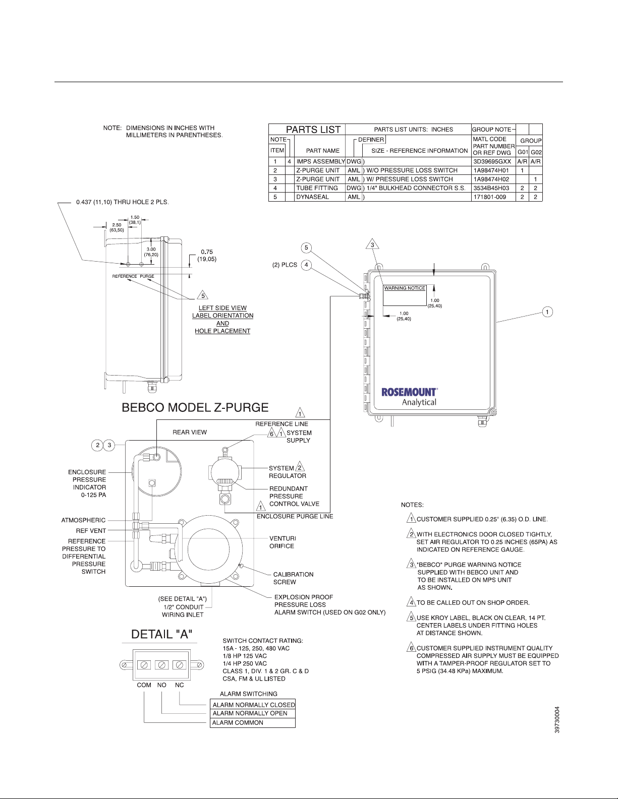
Z-PURGE OPTION Some IMPS applications have area safety requirements (Class 1, Division 2).
These requirements may be satisfied with the installation of an optional
Z-purge. The Z-Purge provides positive pressure within the IMPS 4000
enclosure to keep out dust and other foreign matter. Figure 1-4 shows the
Z-purge unit and how it connects to the IMPS 4000.
SPECIFICATIONS
Feature Specification
Electrical Classification NEMA 4X (IP56)
Humidity Range 95% Relative Humidity
Ambient Temperature Range*
w/o Heater Option
w/ Heater Option
Input Power*
w/o Heater Option
w/ 115 V Nominal Heater (Optional)
w/ 220 V Nominal Heater (Optional)
External Electrical Noise Minimum Interference
Handshake Signal to/from Oxygen
Transmitter (Self-Powered)
Cal Initiate Contact Input from
Control Room (One per Probe) 24 VDC (Self-Powered)
Relay Outputs to Control Room
(One "In-Cal" per Probe, "Low
Gas Flowing," "High Gas
Flowing, "One "Cal Failed" per
Probe, "Gas Pressure Low"
Cabling Distance Between IMPS 4000
and Oxygen Transmitter
Cabling Distance Between IMPS 4000
and Customer-Supplied Status
Relay I/O in Control Room
Piping Distance Between IMPS 4000
and Oxygen Transmitter
Approximate Shipping Weight 40 lbs (18 kg)
*If using the heater option, the low temperature value of the ambient temperature range may vary depending on
the input voltage supply.
32° to 131°F (0° to 55°C)
-35° to 131°F (-37° to 55°C)
90 to 250 V, 50/60 Hz, 50 VA
115 V Nominal, 50/60 Hz, 200 VA
230 V Nominal, 50/60 Hz, 200 VA
5 V (5 mA Maximum)
5 to 30 VDC Form A (SPST),
1.5 A per point, 3 A total per common
1000 ft (303 m) Maximum
1000 ft (303 m) Maximum
300 ft (91 m) Maximum
1-5
Page 14
4000 IMPS
Figure 1-4. IMPS 4000 with Z-Purge
Instruction Manual
IM-106-400 IMPS, Rev. 2.0
February 2009
1-6
Page 15
Instruction Manual
IM-106-400 IMPS, Rev. 2.0
February 2009
4000 IMPS
Section 2 Installation
Overview . . . . . . . . . . . . . . . . . . . . . . . . . . . . . . . . . . . . . . . page 2-1
Mechanical Installation . . . . . . . . . . . . . . . . . . . . . . . . . . . page 2-2
Gas Connections . . . . . . . . . . . . . . . . . . . . . . . . . . . . . . . . page 2-3
Electrical Connections . . . . . . . . . . . . . . . . . . . . . . . . . . . . page 2-4
Switch Settings . . . . . . . . . . . . . . . . . . . . . . . . . . . . . . . . . . page 2-6
OVERVIEW This section describes the installation requirements for the IMPS 4000
Intelligent Multiprobe Test Gas Sequencer.
Before starting to install this equipment, read the “Safety Instructions for the Wiring and
Installation of this Apparatus” in Appendix A of this Instruction Manual. Failure to follow the
safety instructions could result in injury or death.
Install all protective equipment covers and safety ground leads after installation. Failure to
install covers and ground leads could result in serious injury or death.
http://www.raihome.com
Page 16
4000 IMPS
Instruction Manual
IM-106-400 IMPS, Rev. 2.0
February 2009
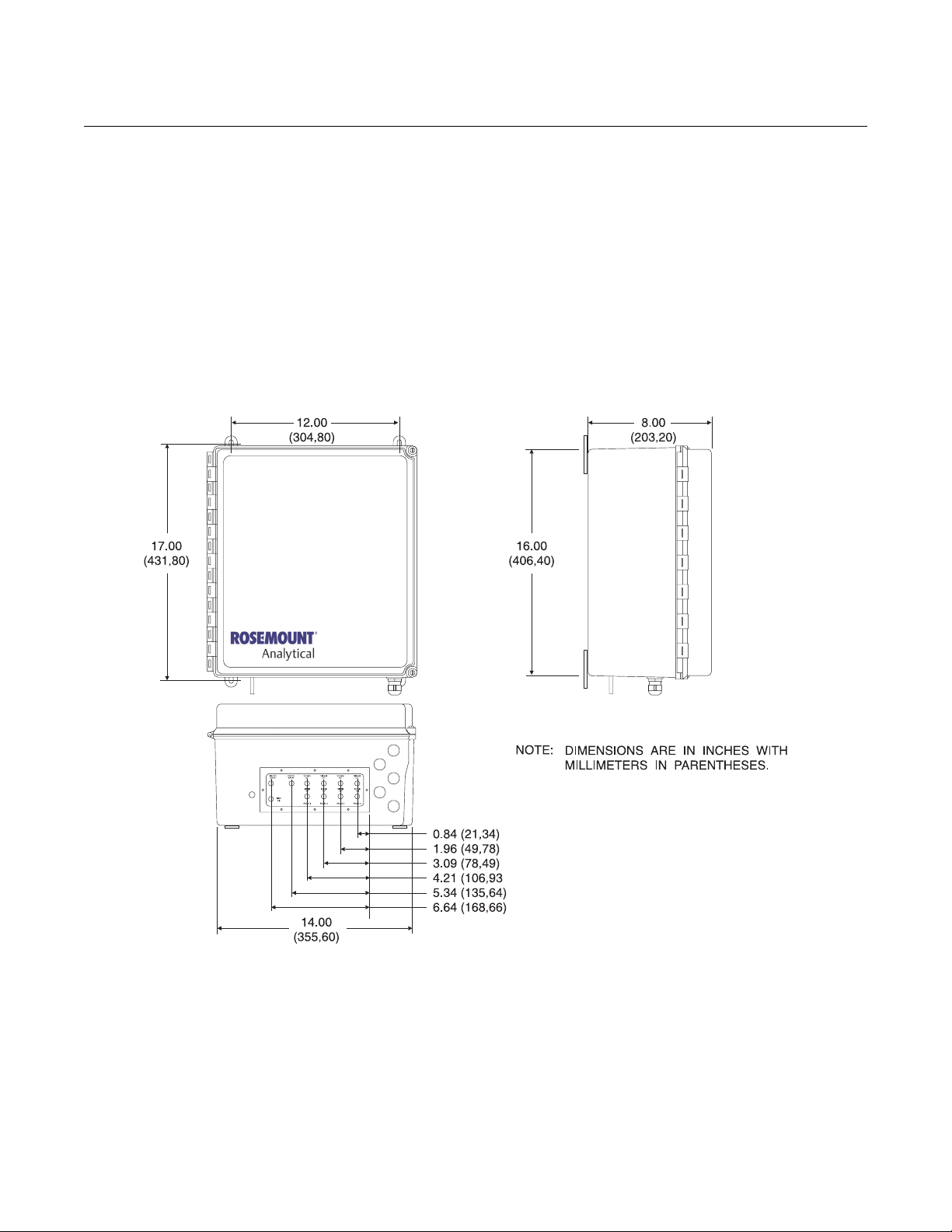
MECHANICAL
INSTALLATION
Figure 2-1. Mounting Dimensions
The outline drawing in Figure 2-1 shows mounting centers and clearances for
the IMPS 4000. The unit is designed to mount on a wall or bulkhead. Ensure
the unit is installed according to the following instructions.
1. Install the module no further than 300 ft (91 m) from the probe and no
further than 1000 ft (303 m) from a remote connection or from the status
relay indicators.
2. Locate units without the optional heater where the ambient temperature
is between 32° and 131°F (0° and 55°C). For units with the optional
heater, install where the ambient temperature is between -35° and
131°F (-37° and 55°C).
2-2
Page 17
Instruction Manual
IM-106-400 IMPS, Rev. 2.0
February 2009
4000 IMPS
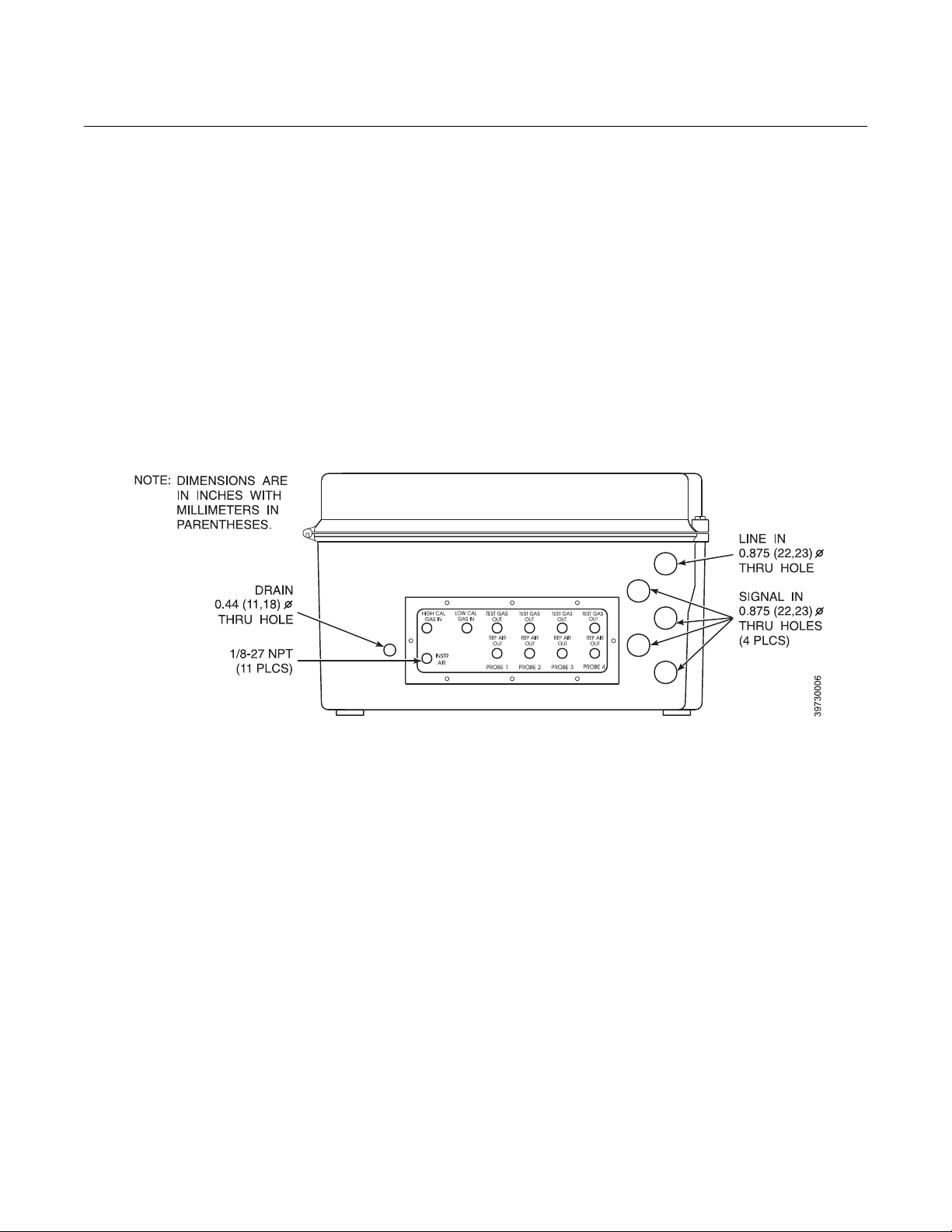
GAS CONNECTIONS Gas connections are located on the bottom of the IMPS 4000 and are 1/8-27
NPT fittings (Figure 2-2). Use the following procedure to connect the test
gases:
1. Connect the reference air supply to INSTR AIR. The pressure regulator
valve is set at the factory to 20 psi (138 kPa). If necessary, readjust by
turning the knob on the top of the valve until the desired pressure is
obtained.
2. Connect the O
should be set at 20 psi (138 kPa).
3. Connect the O
should be set at 20 psi (138 kPa).
4. Connect the oxygen transmitter REF GAS to REF AIR OUT.
5. Connect the oxygen transmitter CAL GAS to TEST GAS OUT.
Figure 2-2. Gas Connections
test gas 1 to HIGH CAL GAS IN. The test gas pressure
2
test gas 1 to LOW CAL GAS IN. The test gas pressure
2
2-3
Page 18

4000 IMPS
Instruction Manual
IM-106-400 IMPS, Rev. 2.0
February 2009
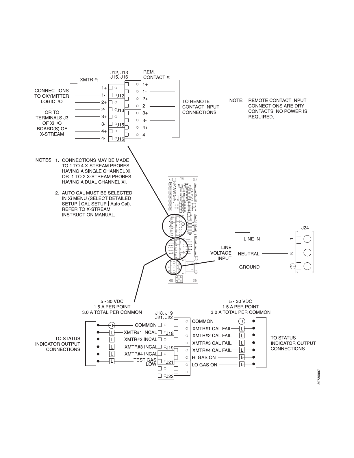
ELECTRICAL
CONNECTIONS
All wiring must conform to local and national codes. Refer to Figure 2-3 and
use the following procedure to connect the first oxygen transmitter. Repeat
the procedure for each remaining oxygen transmitter.
1. Run the line voltage through the bulkhead fitting on the bottom of the
IMPS 4000 marked LINE IN. Connect the line voltage to the J24
terminal. The power supply automatically adjusts to the input voltage.
Tighten the cord grips to provide strain relief.
2. When connecting an Oxymitter O
I/O wires for each oxygen transmitter through a bulkhead fitting on the
bottom of the IMPS 4000 marked SIGNAL IN. Dedicate one fitting for
each oxygen transmitter. Connect the oxygen transmitter logic I/O wires
as shown in Figure 2-3.
3. When connecting an X-STREAM O
signal wires from connector J3 of the Xi I/O board through a bulkhead
fitting on the bottom of the IMPS 4000 marked SIGNAL IN. Dedicate
one fitting for each oxygen transmitter. Connect the oxygen transmitter
handshake signal wires as shown in Figure 2-3.
4. To set up the IMPS 4000 to initiate a calibration from a remote location,
run the remote contact input wires through the SIGNAL IN bulkhead
fitting. Connect the remote contact input wires as shown in Figure 2-3.
5. Status relay connections are available on the IMPS 4000 PC board to
signal when the oxygen transmitter is in or out of calibration and to
indicate calibration gas status. Status relays can be connected to either
indicator lights or a computer interface. Relay contacts are capable of
handling up to 5 to 30 V, 1.5 A per point, 3.0 A total per common
maximum power source. Cabling requirement is 1000 ft (303 m)
maximum. Make the status relay switch connections as shown in
Figure 2-3.
Transmitter, run the handshake logic
2
Transmitter, run the handshake
2
2-4
Page 19
Instruction Manual
IM-106-400 IMPS, Rev. 2.0
February 2009
Figure 2-3. Electrical Connections
4000 IMPS
2-5
Page 20
Instruction Manual
IM-106-400 IMPS, Rev. 2.0
4000 IMPS
February 2009
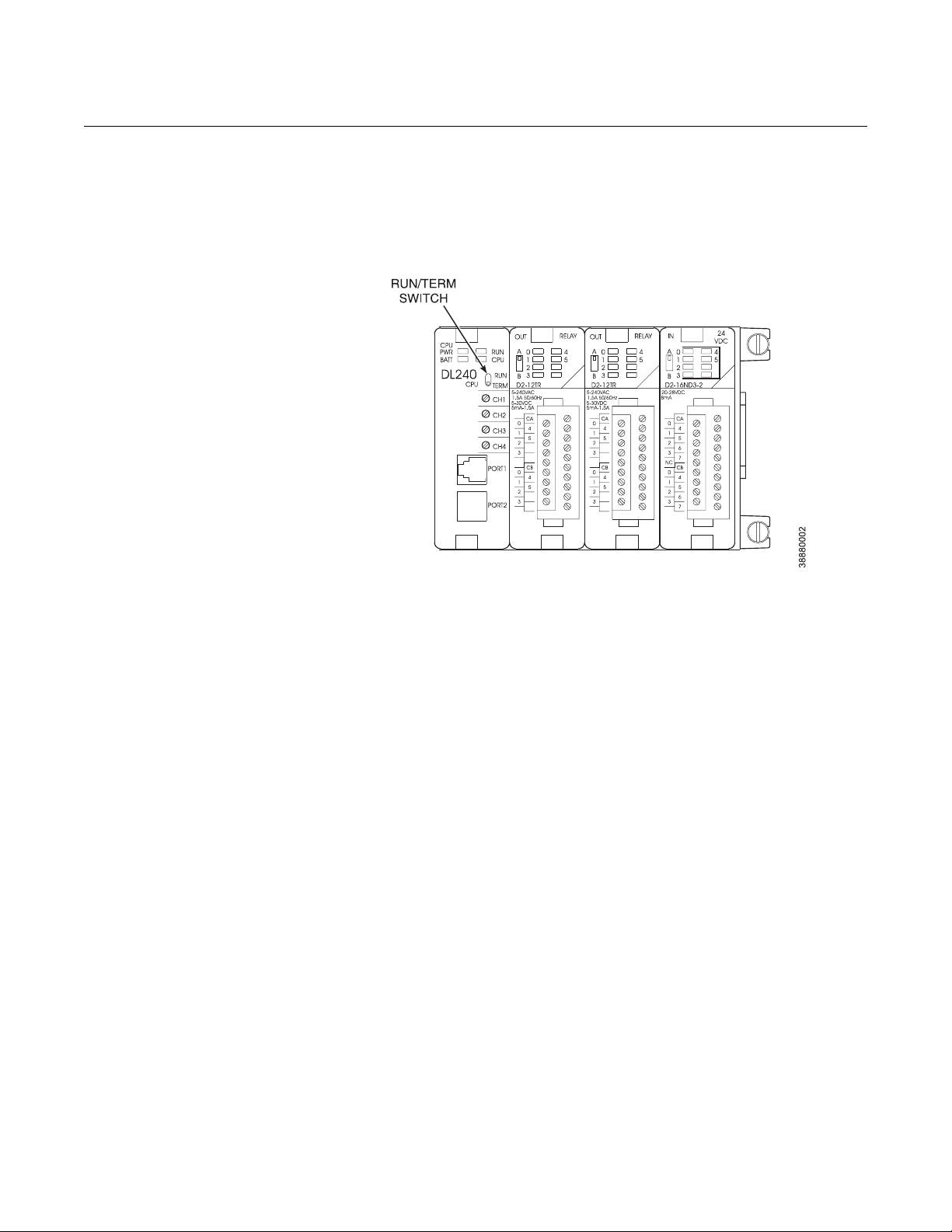
SWITCH SETTINGS The PLC RUN/TERM switch must be in the TERM position for proper
operation. When the RUN/TERM switch is in the RUN position, the PLC will
display an “E525 Keyswitch” error message. Refer to Figure 2-4 and verify
that the RUN/TERM switch is in the RUN position.
Figure 2-4. RUN/TERM Switch
Settings
2-6
Page 21

Instruction Manual
IM-106-400 IMPS, Rev. 2.0
February 2009
4000 IMPS
Section 3 Operation
Overview . . . . . . . . . . . . . . . . . . . . . . . . . . . . . . . . . . . . . . . page 3-1
Calibration Requirements . . . . . . . . . . . . . . . . . . . . . . . . . page 3-1
Operator Interface Description . . . . . . . . . . . . . . . . . . . . . page 3-2
Message Display Mode Parameters . . . . . . . . . . . . . . . . . page 3-5
Test Gas Flow Setup . . . . . . . . . . . . . . . . . . . . . . . . . . . . . . page 3-6
Automatic Calibration . . . . . . . . . . . . . . . . . . . . . . . . . . . . page 3-6
Semi-Automatic Calibration . . . . . . . . . . . . . . . . . . . . . . . . page 3-7
OVERVIEW This section specifies the requirements to set up an oxygen transmitter
calibration. It describes the PLC operator interface and explains how to set up
time-sequenced calibration routines for up to four oxygen transmitters using
the IMPS 4000. This section also explains the differences between automatic
and semi-automatic calibrations and how to initiate them.
CALIBRATION
REQUIREMENTS
The following components are required for an oxygen transmitter calibration
using the IMPS 4000:
1. Two tanks of precision calibration gas mixtures are required.
Recommended calibration gases are nominally 0.4% and 8.0% oxygen
in nitrogen. Two sources of calibrated gas mixtures are:
LIQUID CARBONIC GAS CORP.
SPECIALTY GAS LABORATORIES
700 South Alameda Street
Los Angeles, California 90058
213/585-2154
767 Industrial Road
San Carlos, California 94070
415/592-7303
9950 Chemical Road
Pasadena, Texas 77507
713/474-4141
12054 S.W. Doty Avenue
Chicago, Illinois 60628
312/568-8840
603 Bergen Street
Harrison, New Jersey 07029
201/485-1995
http://www.raihome.com
255 Brimley Road
Scarborough, Ontario, Canada
416/266-3161
Page 22
4000 IMPS
Instruction Manual
IM-106-400 IMPS, Rev. 2.0
February 2009
SCOTT ENVIRONMENTAL
TECHNOLOGY, INC.
SCOTT SPECIALTY GASES
2600 Cajon Blvd.
San Bernardino, California 92411
714/887-2571
TWX: 910-390-1159
1290 Combermere Street
Troy, Michigan 48084
314/589-2950
Route 611
Plumsteadville, Pennsylvania 18949
215/766 8861
TWX: 510-665-9344
2616 South Loop West
Suite 100
Houston, Texas 77054
713/669-0469
OPERATOR INTERFACE
DESCRIPTION
Figure 3-1. Operator Interface
2. A check valve is required at the oxygen transmitter (between the
calibration fitting and the gas line) to prevent the migration of process
gases down the calibration gas line. A typical calibration setup is shown
in Section 1, Figure 1-3 of this manual.
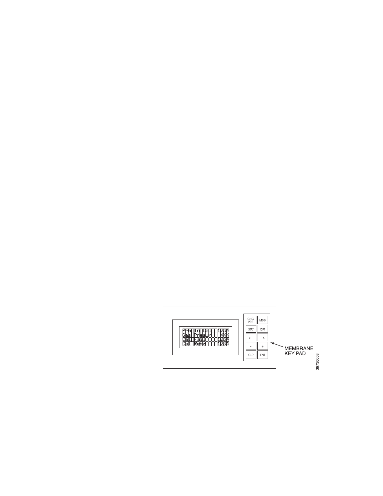
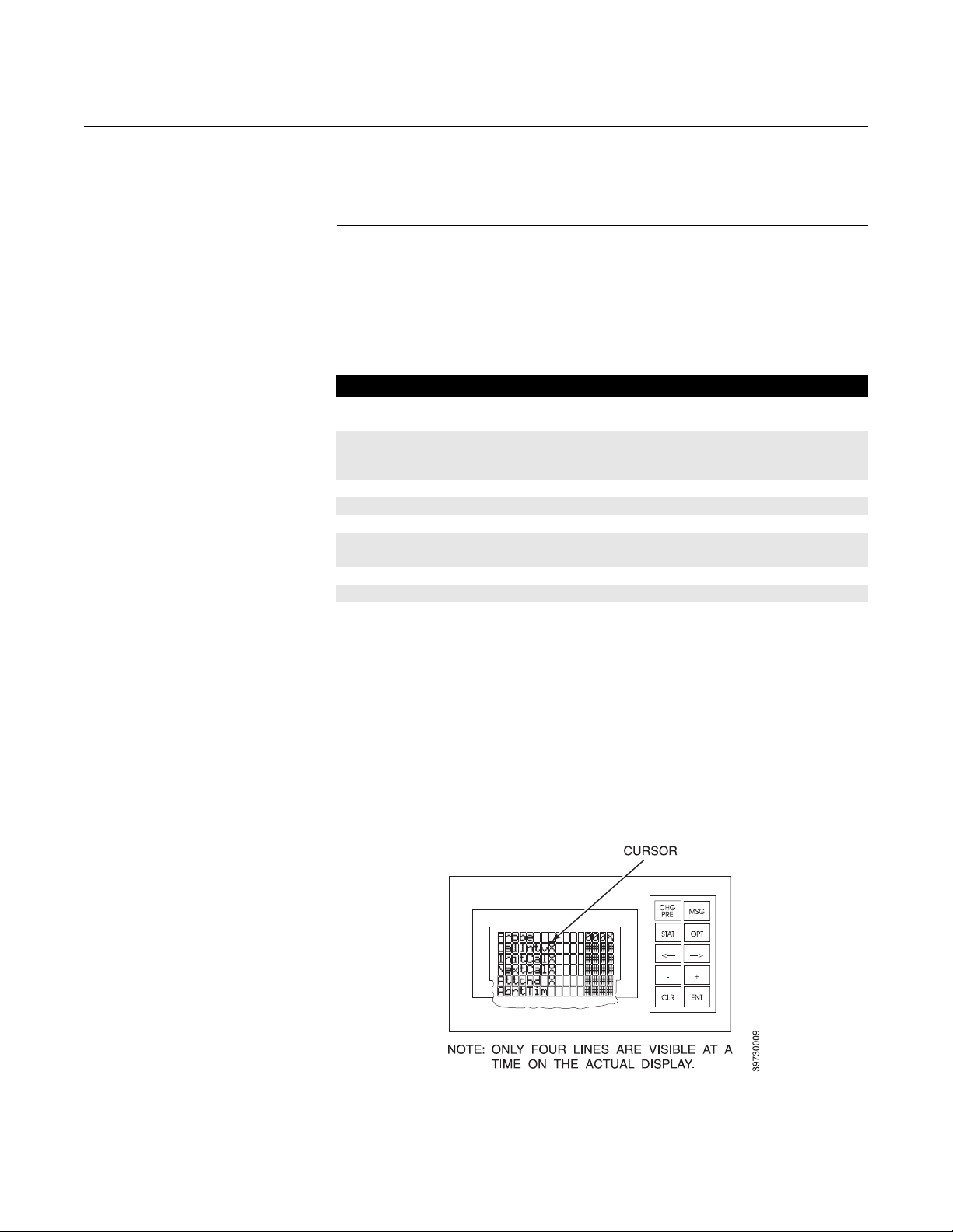
See Figure 3-1. The operator interface consists of a membrane keypad and a
4-line, 16-character, backlit LCD display. The LCD display is divided into two
areas. The left side is a descriptive field that identifies the calibration
parameter. The right side shows the current value or status of the calibration
parameter.
3-2
Page 23
Instruction Manual
IM-106-400 IMPS, Rev. 2.0
February 2009
4000 IMPS
Membrane Keypad The 10-key keypad, shown in Figure 3-1, allows you to toggle between the
two available modes, scroll through the available descriptive fields, and
change data field values. Table 3-1 describes the available membrane keys.
NOTE
Keypad response time is intentionally slow to allow the unit time to process
each keystroke. Please pause between keystrokes.
While viewing the display, note that the cursor appears only on the top line.
Table 3-1. Membrane Key
Descriptions
Name Description
CHG PRE Accesses the change presets display mode. The data fields in this mode
can be changed using the keypad as required for system operation.
MSG Accesses the message display mode. The message display mode
provides IMPS status indications. The data fields indicate current status
and are not changeable by the operator.
STAT Not used.
OPT Not used.
Left/Right Arrow Moves the cursor left and right in the data field.
Plus/Minus Sign Moves the text to the cursor when in a descriptive field or increases and
decreases the data value highlighted by the cursor when in a data field.
CLR Not used.
ENT Toggles the cursor between the descriptive and data fields.
LCD Display The two available display modes are the Editable Change Presets Display
Mode and the view-only Message Display Mode.
1. Refer to Figure 3-2. The front panel display is only accessible when the
noted switch is in the “TERM” position.
2. The Change Presets Display Mode shown in Figure 3-2 identifies the six
parameters necessary to program time-sequenced, automatic
calibration routines for up to four oxygen transmitters and to initiate a
semi-automatic calibration. Table 3-2 explains the calibration
parameters used in the Change Presets Display Mode.
Figure 3-2. Change Presets
Display Mode
3-3
Page 24

4000 IMPS
Table 3-2. Change Preset
Display Mode Parameters
Instruction Manual
IM-106-400 IMPS, Rev. 2.0
February 2009
Parameter
Name
In the following parameters, X indicates the oxygen transmitter number (1 through 4).
Probe 0001 to
Data
Display
0004
Description
NOTE
This parameter sets/identifies the specific oxygen transmitter for
setup/review. Only the least significant digit is editable.
* CalIntvX 0001 to
9998,
9999
* InitCalX or
AbrtCalX
* NextCalX 0001 to
Attchd X 0000 or
AbrtTim X 0001 to
0000 or
0001
9997
0001
9999
CalIntvX sets/indicates the number of hours between automatic
calibrations. The range is 0001 to 9998 hours. Setting the
parameter to 9999 intentionally does not establish a timed
calibration interval.
When no calibration is taking place, InitCalX displays. Changing
the 0000 parameter to 0001 initiates oxygen transmitter
calibration. Only the least significant digit is editable.
The display changes to AbrtCalX when the specified oxygen
transmitter is undergoing calibration. Changing the 0001
parameter to 0000 aborts oxygen transmitter calibration. Only
the least significant digit is editable.
NextCalX sets/indicates the number of hours until the next
timed calibration. The maximum allowable value is the CalIntvX
value specified for the oxygen transmitter.
Attchd X indicates whether or not the specified oxygen
transmitter is connected to the IMPS 4000. A 0000 value
indicates the oxygen transmitter is not connected. A 0001 value
indicates the oxygen transmitter is connected. Only the least
significant digit is editable.
This parameter is also useful to reset the oxygen transmitter if
the oxygen transmitter and the IMPS 4000 lose their
communication link.
AbrtTim X indicates the time (in tenths of seconds) that the
IMPS 4000 will wait for a step signal from the oxygen
transmitter. This parameter limits the amount of time that gas
will flow if communications between the IMPS 4000 and the
oxygen transmitter are disrupted.
3-4
The PLC operator interface holds only one value for the AbrtTim
X. If the AbrtTim X is changed, it changes for all the oxygen
transmitters connected to the IMPS 4000.
This parameter value must be greater than the highest dwell
time of all the oxygen transmitters connected to the IMPS 4000.
Refer to the Oxymitter 4000 or the X-STREAM Instruction
Manual for more information on dwell time. If no signal is
received from the oxygen transmitter within the AbrtTim X
specified, the calibration gas turns off and the sequence aborts.
Page 25

Instruction Manual
IM-106-400 IMPS, Rev. 2.0
February 2009
Figure 3-3. Message Display
Mode
Table 3-3. Message Display
Mode Parameters
4000 IMPS
3. The Message Display Mode shown in Figure 3-3 is a display-only mode
that shows the current calibration status od the the IMPS 4000. The
parameters are not changeable by the user. Table 3-3 decribes the
calibration status displays that are shown in the Message Display Mode
mode.
Parameter
Name
Prb in Cal none, 1, 2, 3,
Gas Presur OK or LOW Gas Presur indicates if the calibration gas pressure is high
Cal Fail none, 1, 2, 3,
Cal Reqd none or 1, 2,
Data
Display
or 4
or 4
3, and/or 4
Description
Prb in Cal indicates the oxygen transmitter currently undergoing
calibration. If no oxygen transmitter is being calibrated, the
parameter displays none.
enough for calibration. OK indicates the pressure is high
enough. LOW indicates the calibration gas pressure is too low
and calibration will not occur.
If an oxygen transmitter fails calibration, Cal Fail displays the
oxygen transmitter number. If the oxygen transmitter does not
fail calibration, Cal Fail displays none.
Cal Reqd displays the oxygen transmitter(s) waiting to be
calibrated when another oxygen transmitter is in calibration.
More than one oxygen transmitter can display at one time. If no
oxygen transmitter is waiting to be calibrated, Cal Reqd displays
none.
USING THE OPERATOR
The following paragraphs describe how to use the operator interface.
INTERFACE
Selecting a Parameter The cursor only appears on the top line of the Change Presets Display Mode.
To access a parameter, scroll the parameter to the top line of the display.
Pressing the + key scrolls down the list. Pressing the - key scrolls up the list.
The list of parameters will continuously scroll in either direction when at the
top or bottom of the display.
NOTE
The PLC operator interface only uses the Change Presets Display Mode and
the Message Display Mode. If a screen displays that you do not recognize,
press the CHG PRE or MSG key to exit the unfamiliar screen.
3-5
Page 26

4000 IMPS
Instruction Manual
IM-106-400 IMPS, Rev. 2.0
February 2009
Changing a Typical
Parameter
Once the parameter you want to change is at the top line, use the ENT key to
move the cursor from the descriptive field to the data field. In the data field,
use the left or right arrow key to move the cursor left or right in the data field.
Next use the + or - key to increase or decrease the data value highlighted by
the cursor.
TEST GAS FLOW SETUP After setting up the parameters in Table 3-2, calibrate each oxygen transmitter
to verify IMPS 4000 operation and the communication link between the
sequencer and the oxygen transmitter.
1. Verify that both test gases are connected to the IMPS 4000 and the
operator interface Gas Pressure parameter in the Message Display
Mode indicates OK. Also verify that the pressure regulators on both test
gas bottles are set to 20 psig (138 kPag).
2. Initiate a semi-automatic calibration using one of the methods specified
in the Semi-Automatic Calibration discussion that follows.
NOTE
The test gas flowmeter should be adjusted only upon initial installation and
after changing the diffusion element in the oxygen transmitter. Refer to the
flowmeter adjustments procedure in Section 5, Maintenance and Service for
more information.
3. As the IMPS 4000 and oxygen transmitter apply the first test gas, set
the test gas flowmeter to 5 scfh. During the application of the second
test gas, verify that the flowmeter reads 5 scfh. If not, adjust the
pressure regulator on the second test gas bottle to get a 5 scfh flow.
AUTOMATIC
CALIBRATION
Automatic calibrations require no operator action. Automatic calibrations are
performed through the time-sequenced calibrations programmed through the
IMPS 4000 or through oxygen transmitter CAL RECOMMENDED feature.
IMPS 4000. The calibration routines programmed into the IMPS 4000 are
automatic calibrations. After setting up the calibration routines using the PLC
operator interface, the oxygen transmitters can calibrate on a time-sequenced
schedule without any user intervention.
Oxymitter 4000 O
a handshake with the IMPS 4000, an automatic calibration starts when the
CAL RECOMMENDED alert becomes active. Enable automatic calibration
using one the following (HART or LOI) instruction sets.
1. Using the HART Communications menu:
a. Select DETAILED SETUP | OUTPUT CONDITION | ALARM
OUTPUT | Logic IO Pin Mode | Mode 8 to enable calibration on a
CAL RECOMMENDED alarm.
b. Select DETAILED SETUP | OUTPUT CONDITION | ALARM
OUTPUT | Logic IO Pin Mode | Mode 9 to calibrate at a specific
interval and DETAILED SETUP | O2 CALIBRATION | Cal Intrvl h to
select the calibration interval (in hours).
c. Select DETAILED SETUP | O2 CALIBRATION | Cal Mode | Auto to
enable the autocalibration mode.
Transmitter. When the Oxymitter 4000 is configured for
2
3-6
Page 27

Instruction Manual
IM-106-400 IMPS, Rev. 2.0
February 2009
4000 IMPS
2. Using the LOI Communications menu:
a. Select SYSTEM | Input/Output | Digital | Logic IO Mode | Mode 8 to
enable calibration on a CAL RECOMMENDED alert.
b. Select SYSTEM | Calib Setup | Auto Calib? | Yes to enable the
autocalibration mode.
SEMI-AUTOMATIC
CALIBRATION
X-STREAM O
Transmitter can be enabled only at the Xi Enhanced Interface. Autocalibration
is not available without the Xi. When the X-STREAM is configured for a
handshake with the IMPS 4000, an automatic calibration starts when a CAL
RECOMMENDED alert becomes active. To enable the autocalibration mode
use the Xi menu to select DETAILED SETUP | CAL SETUP | Auto Cal.
Semi-automatic calibrations require operator initiation. Semi-automatic
calibrations can be performed using the IMPS 4000 keypad, the Oxymitter
keypad, the X-STREAM Xi keypad, the HART field communicator/AMS
software, or a remote contact.
IMPS 4000 Keypad. A semi-automatic calibration can be initiated using the
InitCalX parameter in the change presets display mode. Change the InitCalX
parameter from 0000 to 0001 for the oxygen transmitter to be calibrated. This
semi-automatic calibration will not disturb the automatic, time-sequenced
calibration programmed into the IMPS 4000.
Oxymitter Keypad. For information on initiating a semi-automatic calibration
from the Oxymitter keypad, refer to the Oxymitter 4000 Oxygen Transmitter
Instruction Manual.
Xi Keypad. For information on initiating a semi-automatic calibration from the
Xi keypad, refer to the X-STREAM O
HART Field Communicator/AMS Soft-ware. A semi-automatic calibration
can be initiated by connecting the HART field communicator, or AMS
software, to the oxygen transmitter signal line and initiating the calibration
using the HART field communicator keypad or computer keyboard. Refer to
the Oxymitter 4000 Oxygen Transmitter Instruction Manual, the X-STREAM
O
Oxygen Transmitter Instruction Manual, or the available HART
2
documentation for more information.
Transmitter. An autocalibration of the X-STREAM O2
2
Oxygen Transmitter Instruction Manual.
2
Remote Contact. A semi-automatic calibration can be initiated using a
remote contact such as a customer’s control system. The remote contact
processes the calibration command on the PC and sends a signal to the
oxygen transmitter. For more information on remote-site calibrations, refer to
the documentation for the system in use.
3-7
Page 28

4000 IMPS
Instruction Manual
IM-106-400 IMPS, Rev. 2.0
February 2009
3-8
Page 29

Instruction Manual
IM-106-400 IMPS, Rev. 2.0
February 2009
4000 IMPS
Section 4 Troubleshooting
Overview . . . . . . . . . . . . . . . . . . . . . . . . . . . . . . . . . . . . . . . page 4-1
Troubleshooting . . . . . . . . . . . . . . . . . . . . . . . . . . . . . . . . . page 4-1
Calibration Troubleshooting . . . . . . . . . . . . . . . . . . . . . . . page 4-3
PLC I/O LED Indications . . . . . . . . . . . . . . . . . . . . . . . . . . . page 4-4
OVERVIEW This section describes troubleshooting for the IMPS 4000. Additional
troubleshooting information can be found in the Oxymitter 4000 or
X-STEAM O
Install all protective equipment covers and safety ground leads after troubleshooting. Failure
to replace covers and ground leads could result in serious injury or death.
Transmitter Instruction Manual.
2
TROUBLESHOOTING Table 4-1 provides a guide to fault finding failures within the IMPS 4000. The
flowchart in Figure 4-1 provides an alternate approach to fault finding IMPS
related problems.
Table 4-1. Fault Finding
Symptom Check Fault Remedy
Power to solenoid, test gas
not released to probe
No power to solenoid Power supply output
Test gas
Solenoid
Fuse on PC board
Main power source
Insufficient test gas
Solenoid failure
Power supply failure
Fuse blown
Main power off
Install new test gas tanks.
Replace solenoid.
Replace PLC.
Replace fuse.
Repair power outage.
http://www.raihome.com
Page 30

4000 IMPS
Figure 4-1. IMPS Troubleshooting Flowchart
Instruction Manual
IM-106-400 IMPS, Rev. 2.0
February 2009
4-2
Page 31

Instruction Manual
IM-106-400 IMPS, Rev. 2.0
February 2009
4000 IMPS
CALIBRATION
TROUBLESHOOTING
If the IMPS 4000 is unable to calibrate the oxygen transmitter, use Table 4-2
to determine and correct the problem.
Table 4-2. Cal Fail Fault Finding
Symptom Check Fault Remedy
Cal Fail indicated
in MSG display mode
Cal Reqd indicated
in MSG display mode
but IMPS 4000 cannot
initiate calibration
Test gas
Oxygen transmitter
Handshake signal Loss of synchronization
Test gas pressure low
Transmitter malfunction
O
2
between IMPS 4000 and
O
Transmitter.
2
Check test gas line for obstruction or install
new test gas bottle. When test gas pressure
is OK, initiate a semi-calibration to clear the
fault.
Refer to O
for further troubleshooting information.
1. Set AttchdX to 0000 in the CHG PRE
display mode for that particular O
Transmitter to clear the IMPS 4000
internal registers.
2. Ensure no alarm conditions are indicated
on the O
LED is off. If the green CAL LED is on or
flashing, press the CAL button three times
within one second for the O
to abort the calibration routine.
3. When the O
and no other alarms exist, reset the
AttchdX parameter to 0001.
Transmitter Instruction Manual
2
2
Transmitter and the green CAL
2
Transmitter
2
Transmitter green LED is off
2
Cal Fail indicated in
message display mode but
IMPS 4000 cannot initiate a
calibration
O2 Transmitter indicates a
calibration failure, but IMPS
4000 does not
Handshake signal Loss of synchronization
Handshake signal Loss of synchronization
between IMPS 4000 and
O
Transmitter.
2
between IMPS 4000 and
O
Transmitter.
2
NOTE
The CalIntvX for that particular O
Transmitter resets to 9999 when the O
Transmitter is detached from and reattached
to the IMPS 4000. If a timed calibration is
required for that O
parameter to the appropriate time interval
(in hours).
4. After resetting the IMPS, initiate a
calibration. Observe the O
status outputs. The INCAL contact will
remain closed throughout the calibration
cycle. The HI GAS ON contact will close
for the test gas time set in the O
Transmitter. Shortly after the high gas
contact opens, the LO GAS ON contact
will close for the test gas time.
Refer to remedy for symptom 2.
Refer to remedy 1, 3, and 4 for symptom 2.
Transmitter, set this
2
2
2
Transmitter
2
2
4-3
Page 32

4000 IMPS
Instruction Manual
IM-106-400 IMPS, Rev. 2.0
February 2009
PLC I/O LED
INDICATIONS
Figure 4-2. PLC I/O LEDs
Observing the operation of the PLC inputs and outputs can be a valuable tool
in troubleshooting the operation of the IMPS 4000.
Figure 4-2 displays the PLC I/O LEDs. On each input and output module are
LEDs that correspond to a specific input or output. Each LED can have two
different functions depending on the position of the A/B switch. On the input
I/O module for example, if the switch is in the A position, LED 0 indicates input
X0 operation. If the switch is in the B position, LED 0 indicates input X10
operation.
Table 4-3 and Table 4-4 list each input and output of the I/O modules and its
description. The tables also identify on which module the input or output
resides, what position the A/B switch must be in to identify an I/O using an
LED, the LED number, and notes. These notes explain typical I/O operation
and corrective actions if the LED does not operate as specified.
4-4
Page 33

Instruction Manual
IM-106-400 IMPS, Rev. 2.0
February 2009
Table 4-3. PLC Inputs
Input No. Module No. Switch LED No. Description Note
X0 3 A 0 XMTR #1 Input 1
X1 3 A 1 XMTR #2 Input 1
X2 3 A 2 XMTR #3 Input 1
X3 3 A 3 XMTR #4 Input 1
X5 3 A 5 Gas Pressure Switch 2
X10 3 B 0 Remote Input #1 3
X11 3 B 1 Remote Input #2 3
X12 3 B 2 Remote Input #3 3
X13 3 B 3 Remote Input #4 3
NOTES
1. Energized by a digital output from the oxygen transmitter. If the LED is on steady, it indicates that the IMPS 4000 is not responding to an
oxygen transmitter request for a calibration. To correct, perform the following procedure:
a. Unattach the oxygen transmitter at the IMPS 4000 operator interface.
b. Abort the calibration at the oxygen transmitter. Refer to the O
c. Reattach the oxygen transmitter at the IMPS 4000 operator interface.
2. Energized when test gas pressure is high enough for calibration. Deenergized indicates low gas pressure. If low test gas pressure is
indicated by an unlit LED, verify that the test gas bottles are not empty. Check the piping from the test gas bottles to the IMPS 4000 for
leaks or blockages.
Transmitter Instruction Manual.
2
4000 IMPS
3. Energized when a remote system is requesting calibration. This must be a momentary contact. If the LED is on steady, a malfunction is in
the remote system or there is a short in interconnecting wiring. Locate and correct the problem.
4. RUN/TERM switch should be in the TERM position for proper equipment operation.
4-5
Page 34

Instruction Manual
IM-106-400 IMPS, Rev. 2.0
4000 IMPS
Table 4-4. PLC Outputs
Output No. Module No. Switch LED No. Description Note
Y0 1 A 0 XMTR #1 Reply 1
Y1 1 A 1 XMTR #2 Reply 1
Y2 1 A 2 XMTR #3 Reply 1
Y3 1 A 3 XMTR #4 Reply 1
Y10 1 B 0 XMTR #1 Solenoid 2,8
Y11 1 B 1 XMTR #2 Solenoid 2,8
Y12 1 B 2 XMTR #3 Solenoid 2,8
Y13 1 B 3 XMTR #4 Solenoid 2,8
Y14 1 B 4 Gas 1 Solenoid 3,9
Y15 1 B 5 Gas 2 Solenoid 3,9
Y20 2 A 0 XMTR #1 In Cal 4,10
Y21 2 A 1 XMTR #2 In Cal 4,10
Y22 2 A 2 XMTR #3 In Cal 4,10
Y23 2 A 3 XMTR #4 In Cal 4,10
Y24 2 A 4 Gas Pressure Alarm 5,10
Y30 2 B 0 XMTR #1 Cal Fail 6,10
Y31 2 B 1 XMTR #2 Cal Fail 6,10
Y32 2 B 2 XMTR #3 Cal Fail 6,10
Y33 2 B 3 XMTR #4 Cal Fail 6,10
Y34 2 B 4 Gas 1 On 7,10
Y35 2 B 5 Gas 2 On 7,10
NOTES
1. Energized to reply to an oxygen transmitter. A pulse or a series of pulses will be observed, depending on what portion of the calibration
cycle is being performed. If the LED is on steady, it may indicate a PLC failure. Before replacing the PLC, reset the PLC by powering
down and powering up the IMPS 4000. Monitor the gas application portion of the calibration cycle once again. If the LED is still on steady,
replace the PLC.
2. Energized to select which oxygen transmitter will receive test gas during calibration. It is only energized during the gas application
portion of the calibration cycle.
3. Energized to apply either test gas. It is only energized during the gas application portion of the calibration cycle.
4. Energized when an oxygen transmitter is in calibration.
5. Energized if gas pressure is low.
6. Energized if a calibration has failed.
7. Energized when a test gas is flowing.
8. If energized continuously, reset by unattaching and reattaching the oxygen transmitter at the IMPS 4000 operator interface.
9. If energized longer than the AbrtTim set at the operator interface, reset using the following procedure:
a.Unattach the oxygen transmitter at the IMPS 4000 operator interface.
b.Abort the calibration at the oxygen transmitter. Refer to the Oxygen Transmitter Instruction Manual.
c.Reattach the oxygen transmitter at the IMPS 4000 operator interface.
10. If the output LED is illuminated but the remote indication is off, check the wiring from the IMPS 4000 to the remote device. Make sure the
wiring is in accordance with Figure 2-3. Note that the status outputs from the IMPS 4000 have shared common connections and remote
power is required.
February 2009
4-6
Page 35

Instruction Manual
IM-106-400 IMPS, Rev. 2.0
February 2009
4000 IMPS
Section 5 Maintenance and Service
Overview . . . . . . . . . . . . . . . . . . . . . . . . . . . . . . . . . . . . . . . page 5-1
Fuse Replacement . . . . . . . . . . . . . . . . . . . . . . . . . . . . . . . page 5-3
PLC Replacement . . . . . . . . . . . . . . . . . . . . . . . . . . . . . . . . page 5-3
Operator Interface Replacement . . . . . . . . . . . . . . . . . . . . page 5-5
Solenoid Replacement . . . . . . . . . . . . . . . . . . . . . . . . . . . . page 5-5
Pressure Regulator Maintenance . . . . . . . . . . . . . . . . . . . page 5-6
Flowmeter Adjustments . . . . . . . . . . . . . . . . . . . . . . . . . . . page 5-6
OVERVIEW This section describes service and routine maintenance of the IMPS 4000.
Replacement parts referenced are available from Emerson Process
Management. Refer to Section 6: Replacement Parts for part numbers and
ordering information.
Install all protective equipment covers and safety ground leads after equipment repair or
service. Failure to install covers and ground leads could result in serious injury or death.
Do not operate without doors and covers secure. Servicing requires access to live parts
which can cause death or serious injury. Refer servicing to qualified personnel.
Tampering or unauthorized substitution of components may adversely affect safety of this
product. Use only factory documented components for repair.
Disconnect and lock out power before working on any electrical components.
http://www.raihome.com
Page 36
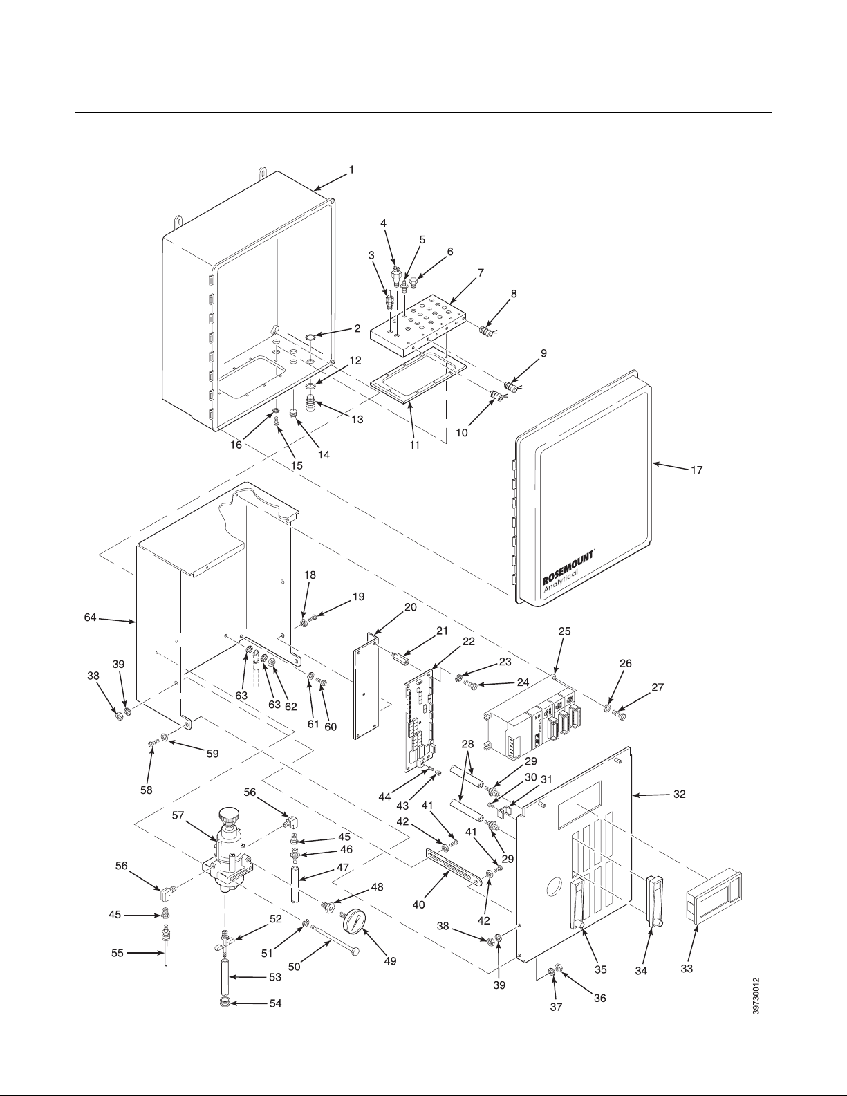
4000 IMPS
Figure 5-1. IMPS 4000, Exploded View
Instruction Manual
IM-106-400 IMPS, Rev. 2.0
February 2009
5-2
Page 37

Instruction Manual
IM-106-400 IMPS, Rev. 2.0
February 2009
Legend for Figure 5-1
Item Description Item Description Item Description
1 Outer Enclosure 22 PC Board 43 Fuseholder
2 Conduit Locknut 23 Washer 44 Fuse
3 Fitting 24 Screw 45 Bushing
4 Pressure Switch 25 PLC 46 Hose Adapter
5 Hose Adapter 26 Washer 47 1/4 in. Tube
6 Plug 27 Screw 48 Bushing
7 Manifold 28 1/8 in. Hose 49 Pressure Gauge
8 O2 Transmitter Gas Solenoid 29 Hose Adapter 50 Bolt
9 Test Gas 2 Solenoid 30 Screw 51 Washer
10 Test Gas 1 Solenoid 31 Bracket 52 Drain Valve
11 Gasket 32 Flow Panel 53 1/8 in. Impolene Drain Tube
12 Seal 33 Operator Interface 54 Grommet
13 Cable Grip 34 Test Gas Flowmeter, 10 scfh 55 Connector
14 Plug 35 Ref. Gas Flowmeter, 2 scfh 56 Elbow
15 Screw 36 Nut 57 Pressure Regulator
16 Washer 37 Washer 58 Screw
17 Outer Cover 38 Nut 59 Washer
18 Washer 39 Washer 60 Screw
19 Screw 40 Slide 61 Washer
20 Mounting Bracket 41 Screw 62 Nut
21 Standoff 42 Washer 63 Washer
64 Inner Enclosure
4000 IMPS
FUSE REPLACEMENT The IMPS 4000 has a fuse on the PC board. Refer to Table 6-1 for
replacement fuse specifications. Perform the following procedure to check or
replace the fuse.
1. Turn off power to the system.
2. Open outer cover (17, Figure 5-1).
3. Loosen the two captive screws holding flow panel (32). Lower the flow
panel.
4. Remove fuseholder (43) by pushing in the top and turning 1/4 turn
counterclockwise. Remove fuse (44).
5. After checking or replacing fuse (44), install fuseholder (43) by pushing
in the top and turning 1/4 turn clockwise.
6. Raise and secure flow panel (32) with two captive screws. Close outer
cover (17).
PLC REPLACEMENT Perform the following procedure to replace a PLC.
1. Turn off power to the system.
2. Open outer cover (17, Figure 5-1).
3. Loosen the two captive screws holding flow panel (32). Lower the flow
panel.
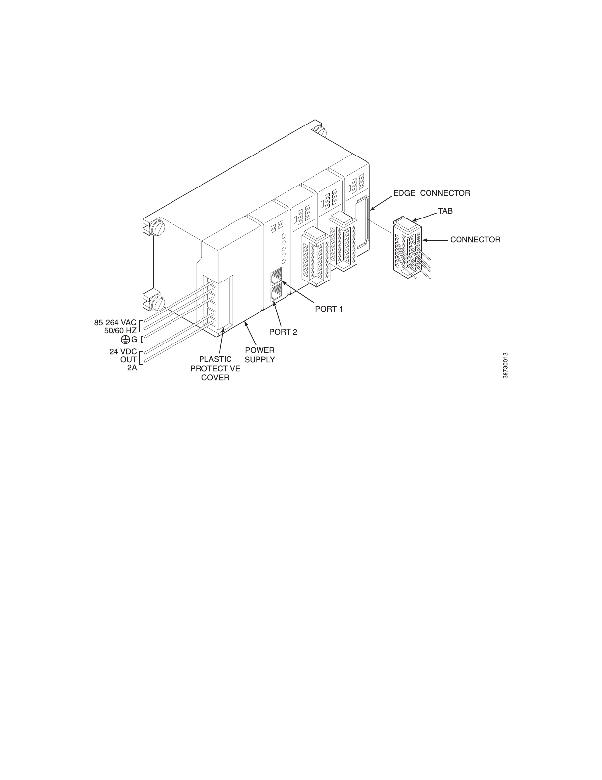
4. Remove the plastic protective cover over the PLC power supply terminal
block (Figure 5-2).
5. Tag and remove the wires shown in Figure 5-2 from the PLC power
supply terminal block.
6. Remove the operator interface jack from PORT 2 on the CPU.
5-3
Page 38
4000 IMPS
Figure 5-2. PLC Connections
Instruction Manual
IM-106-400 IMPS, Rev. 2.0
February 2009
7. Tag the three connectors connected to the I/O modules. To remove
each connector, squeeze together the top and bottom connector tabs
and pull the connector from the I/O module.
8. Remove PLC (25, Figure 5-1) from inner enclosure (64) by removing
four screws (27) and washers (26).
9. Mount new PLC (25) to inner enclosure (64) using four washers (26)
and screws (27).
10. Refer to Figure 5-2. Carefully install the connectors in the I/O modules.
While squeezing the top and bottom tabs together on the connector,
align the connector to the I/O module edge connector. Firmly press the
connector into place until it seats in the I/O module and the tabs click
into place. Verify that you are installing the connectors in the same
location as removed in step 7.
11. Install the operator interface jack in PORT 2 on the CPU.
12. Install the wires to the PLC power supply terminal block.
13. Install the plastic protective cover in the grooves over the power supply
terminals.
14. Raise and secure flow panel (32, Figure 5-1) with two captive screws.
Close outer cover (17).
5-4
Page 39

Instruction Manual
IM-106-400 IMPS, Rev. 2.0
February 2009
4000 IMPS
OPERATOR INTERFACE
REPLACEMENT
SOLENOID
REPLACEMENT
Perform the following procedure to replace an operator interface.
1. Turn off power to the system.
2. Open outer cover (17, Figure 5-1).
3. Loosen the two captive screws holding flow panel (32). Lower the flow
panel.
4. Disconnect the operator interface jack from PORT 2 of the PLC. Refer
to Figure 5-2.
5. From the inner side of flow panel (32, Figure 5-1), squeeze in the two
tabs on either side of operator interface (33) and push the interface
through the front of the flow panel.
6. Install new operator interface (33) by threading the cord through the
interface mounting hole in flow panel (32).
7. Press operator interface (33) into flow panel (32) until the tabs click into
place.
8. Plug the operator interface jack into PORT 2 of the PLC. Refer to
Figure 5-2.
9. Raise and secure flow panel (32, Figure 5-1) with two captive screws.
Close outer cover (17).
The IMPS 4000 manifold (7, Figure 5-1) has a HI GAS (test gas 1) solenoid
(10), a LOW GAS (test gas 2) solenoid (9), and a solenoid (8) for each oxygen
transmitter connected to the unit.
1. Turn off power to the system.
2. Shut off the test gases at the cylinders.
3. Open outer cover (17).
4. Loosen the two captive screws holding flow panel (32). Lower the flow
panel.
5. Disconnect the HI GAS (J2), LOW GAS (J4), or oxygen transmitter
(J5, J7, J8, or J9) plug from its receptacle on PC board (22).
6. Loosen the retaining ring in the middle of the solenoid and remove the
top part.
7. With a spanner wrench or padded pliers, remove the remaining part of
the solenoid from manifold (7).
8. Separate the new solenoid and screw the smaller part into manifold (7).
9. Place the top part of the solenoid into position and tighten the retaining
ring.
10. Connect the plug to the proper receptacle on PC board (22).
11. Raise and secure flow panel (32) with two captive screws. Close outer
cover (17).
12. Turn on the test gases at the cylinders.
5-5
Page 40

Instruction Manual
IM-106-400 IMPS, Rev. 2.0
4000 IMPS
February 2009
PRESSURE
REGULATOR
MAINTENANCE
Pressure Adjustments Pressure regulator (57, Figure 5-1) is factory set to 20 psi (138 kPa). Adjust
using the knob on top of the pressure regulator if necessary.
Condensation Drain To drain excess moisture from the internal gas circuit of the IMPS 4000,
periodically loosen drain valve (52) on the bottom of pressure regulator (57).
The moisture will flow through drain tube (53) on the bottom of the pressure
regulator and exit the bottom of outer enclosure (1).
FLOWMETER
ADJUSTMENTS
Reference Gas
Flowmeter
Reference gas flowmeter (35, Figure 5-1) regulates the reference gas and
must be set to 2 scfh. Adjust the flow with the knob on the bottom of the
respective reference gas flowmeter when necessary.
Test Gas Flowmeter Test gas flowmeter (34) regulates the test gas flow and must be set to 5 scfh.
However, only adjust the flowmeter to 5 scfh after placing a new diffusion
element on the end of the oxygen transmitter. Adjusting the flowmeter at any
other time can pressurize the cell and bias the calibration.
In applications with a heavy dust loading, the O
becomes plugged over time, causing a slower speed of response. The best
way to detect a plugged diffusion element is to note the time it takes the
oxygen transmitter to return to the normal process reading after the last test
gas is removed and the test gas line is blocked off. A plugged element also
can be indicated by a slightly lower reading on the flowmeter.
Change the diffusion element when the test gas flowmeter reads slightly lower
during calibration or when the response time to the process flue gases
becomes very slow. Each time the diffusion element is changed, reset the test
gas flowmeter to 5 scfh and calibrate the oxygen transmitter. For more
information on changing the diffusion element, refer to the Oxymitter 4000 or
the X-STREAM Instruction Manual.
probe diffusion element
2
5-6
Page 41

Instruction Manual
IM-106-400 IMPS, Rev. 2.0
February 2009
Section 6 Replacement Parts
4000 IMPS
REPLACEMENT PARTS
Table 6-1 provides a list of replacement parts for the IMPS 4000.
LIST
Table 6-1. Replacement Parts for the IMPS 4000
Figure, Item Part Number Description
5-1, 8, 9, and 10 3D39435G01* Solenoid
5-1, 44 1A97913H03 Fuse, 5A @ 250 Vac, Slow Blow
5-1, 34 771B635H01* Flowmeter Assembly - Test Gas
5-1, 35 771B635H02* Flowmeter Assembly - Reference Gas
1A98631 Probe Adder Kit
5-1, 29 1A97953H01* Hose Adapter
4847B46H01* Tubing Length
4847B46H02* Tubing Length
4847B46H03* Tubing Length
4847B46H04* Tubing Length
1-3 7307A56G02 Check Valve
5-1, 33 1A98972H01 Operator Interface
5-1, 25 PLC
1A98969H01 PLC 4-Slot Base, 110/220 VDC Power Supply
1-2 1A98967H01 CPU, programmed
1A98968H01 CPU Battery
4-2 1A98970H01 DC Input Module
4-2 1A98971H01 Relay Output Module
5-1, 22 3D39681G01 PC Board
* These items are included in the probe adder kit.
http://www.raihome.com
Page 42

4000 IMPS
Instruction Manual
IM-106-400 IMPS, Rev. 2.0
February 2009
6-2
Page 43

Instruction Manual
IM-106-400 IMPS, Rev. 2.0
February 2009
Appendix A Safety Data
4000 IMPS
http://www.raihome.com
Page 44

4000 IMPS
SAFETY INSTRUCTIONS IMPORTANT
SAFETY INSTRUCTIONS FOR THE WIRING
AND INSTALLATION OF THIS APPARATUS
The following safety instructions apply specifically to all EU member
states. They should be strictly adhered to in order to assure compliance
with the Low Voltage Directive. Non-EU states should also comply with
the following unless superseded by local or National Standards.
1. Adequate earth connections should be made to all earthing points,
internal and external, where provided.
2. After installation or troubleshooting, all safety covers and safety grounds
must be replaced. The integrity of all earth terminals must be maintained
at all times.
3. Mains supply cords should comply with the requirements of IEC227 or
IEC245.
4. All wiring shall be suitable for use in an ambient temperature of greater
than 75°C.
5. All cable glands used should be of such internal dimensions as to
provide adequate cable anchorage.
6. To ensure safe operation of this equipment, connection to the mains
supply should only be made through a circuit breaker which will
disconnect all
circuit breaker may also include a mechanically operated isolating
switch. If not, then another means of disconnecting the equipment from
the supply must be provided and clearly marked as such. Circuit
breakers or switches must comply with a recognized standard such as
IEC947. All wiring must conform with any local standards.
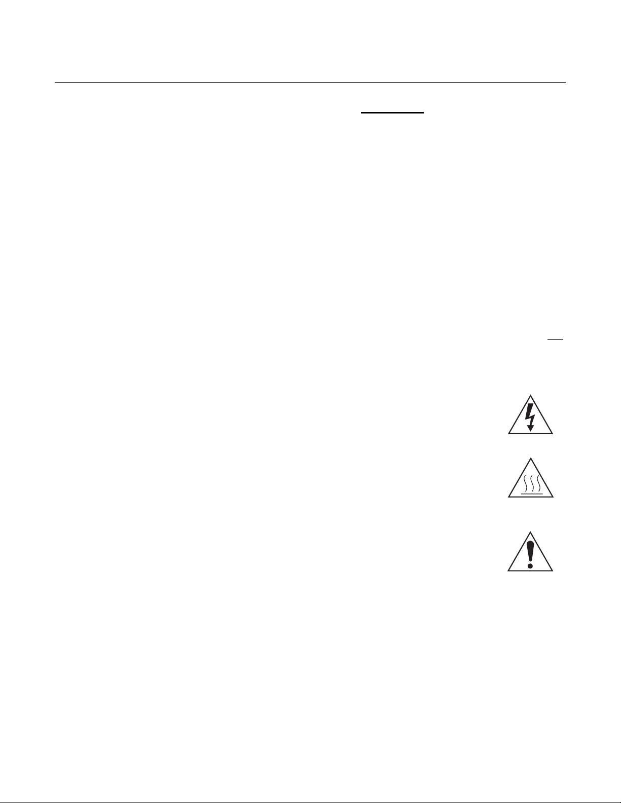
7. Where equipment or covers are marked with the symbol
to the right, hazardous voltages are likely to be present
beneath. These covers should only be removed when
power is removed from the equipment - and then only
by trained service personnel.
8. Where equipment or covers are marked with the symbol
to the right, there is a danger from hot surfaces beneath.
These covers should only be removed by trained
service personnel when power is removed from the
equipment. Certain surfaces may remain hot to the
touch.
9. Where equipment or covers are marked with the symbol
to the right, refer to the Operator Manual for instructions.
10. All graphical symbols used in this product are from one
or more of the following standards: EN61010-1, IEC417,
and ISO3864.
11. Where equipment or labels are marked "Do Not Open While Energized"
or similar, there is a danger of ignition in areas where an explosive
atmosphere is present. This equipment should only be opened when
power is removed and adequate time as specified on the label or in the
instruction manual has been allowed for the equipment to cool down and then only by trained service personnel.
circuits carrying conductors during a fault situation. The
Instruction Manual
IM-106-400 IMPS, Rev. 2.0
February 2009
A-2
Page 45

Instruction Manual
IM-106-400 IMPS, Rev. 2.0
February 2009
4000 IMPS
DŮLEŽITÉ
Bezpečnostní pokyny pro zapojení a instalaci zařízení
Následující bezpečnostní pokyny se speciálně vztahují na všechny
členské státy EU. Pokyny by měly být přísně dodržovány, aby se
zajistilo splnění Směrnice o nízkém napětí. Pokud nejsou pokyny
nahrazeny místními či národními normami, měly by je dodržovat i
nečlenské státy EU.
1. U všech zemnicích bodů, interních a externích, by mělo být vytvořeno
odpovídající uzemnění.
2. Po instalaci nebo odstranění problémů musí být vyměněny všechny
bezpečnostní kryty a uzemnění. Vždy musí být zajištěna integrita všech
zemnicích svorek.
3. Sí˙ové kabely by měly odpovídat požadavkům normy IEC227 nebo
IEC245.
4. Všechna zapojení by měla být vhodná pro použití při vnějších teplotách
nad 75 °C.
5. Všechna použitá kabelová hrdla by měla mít takové vnitřní rozměry, aby
zajistila odpovídající zakotvení kabelu.
6. Správnou činnost zařízení zajistíte, vytvoříte-li připojení k napájecímu
zdroji pouze přes jistič, který v případě
s konduktory. Jistič může také obsahovat mechanický odpojovač.
Pokud ho neobsahuje, musí být zajištěn a jasně označen jiný způsob
odpojení zařízení od zdroje. Jističe nebo přepínače musí odpovídat
uznávaným normám, např. IEC947. Všechna zapojení musí odpovídat
místním normám.
7. Je-li zařízení nebo kryt označen symbolem na pravé
straně, pravděpodobně se uvnitř nachází nebezpečné
napětí. Tyto kryty by měly být sejmuty pouze po
odpojení zařízení od zdroje - a to pouze kvalifikovaným
zaměstnancem.
8. Je-li zařízení nebo kryt označen symbolem na pravé
straně, povrch zařízení může být velmi horký. Tyto kryty
by měly být sejmuty pouze kvalifikovaným
zaměstnancem po odpojení zařízení od zdroje. Některé
povrchy mohou být stále horké.
9. Je-li zařízení nebo kryt označen symbolem na pravé
straně, přečtěte si nejprve instrukce v návodu k obsluze.
10. Všechny grafické symboly používané u výrobku
pocházejí z následujících norem: EN61010-1, IEC417 a
ISO3864.
11. Pokud je zař
napětím, neotvírejte jej“ či podobným, může dojít ve výbušném prostředí
ke vznícení. Zařízení lze otevřít pouze po jeho odpojení od zdroje a
ponechání dostatečného času na vychladnutí, jak je uvedeno na štítku
nebo v návodu k obsluze - a to pouze kvalifikovaným zaměstnancem.
ízení nebo štítky označeno varováním „Je-li zařízení pod
poruchy odpojí všechny obvody
A-3
Page 46
4000 IMPS
Instruction Manual
IM-106-400 IMPS, Rev. 2.0
February 2009
VIGTIGT
Sikkerhedsinstruktion for tilslutning og installering af dette udstyr.
Følgende sikkerhedsinstruktioner gælder specifikt i alle
EU-medlemslande. Instruktionerne skal nøje følges for overholdelse af
Lavsspændingsdirektivet og bør også følges i ikke EU-lande medmindre
andet er specificeret af lokale eller nationale standarder.
1. Passende jordforbindelser skal tilsluttes alle jordklemmer, interne og
eksterne, hvor disse forefindes.
2. Efter installation eller fejlfinding skal alle sikkerhedsdæksler og
jordforbindelser reetableres.
3. Forsyningskabler skal opfylde krav specificeret i IEC227 eller IEC245.
4. Alle ledningstilslutninger skal være konstrueret til omgivelsestemperatur
højere end 75°C.
5. Alle benyttede kabelforskruninger skal have en intern dimension, så
passende kabelaflastning kan etableres.
6. For opnåelse af sikker drift og betjening skal der skabes beskyttelse
mod indirekte berøring gennem afbryder (min. 10A), som vil afbryde alle
kredsløb med elektriske ledere i fejlsitua-tion. Afbryderen skal indholde
en mekanisk betjent kontakt. Hvis ikke skal anden form for afbryder
mellem forsyning og udstyr benyttes og mærkes som sådan. Afbrydere
eller kontakter skal overholde en kendt standard som IEC947.
7. Hvor udstyr eller dæksler er mærket med dette symbol,
er farlige spændinger normalt forekom-mende bagved.
Disse dæksler bør kun afmonteres, når
forsyningsspændingen er frakoblet - og da kun af
instrueret servicepersonale.
8. Hvor udstyr eller dæksler er mærket med dette symbol,
forefindes meget varme overflader bagved. Disse
dæksler bør kun afmonteres af instrueret
servicepersonale, når forsyningsspænding er frakoblet.
Visse overflader vil stadig være for varme at berøre i op
til 45 minutter efter frakobling.
9. Hvor udstyr eller dæksler er mærket med dette symbol,
se da i betjeningsmanual for instruktion.
10. Alle benyttede grafiske symboler i dette udstyr findes i
én eller flere af følgende standarder:- EN61010-1,
IEC417 & ISO3864.
11. Når udstyr eller etiketter er mærket "Må ikke åbnes, mens udstyret
tilføres strøm” eller lignende, er der fare for antændelse i områder, hvor
der er en eksplosiv atmosfære. Dette udstyr må kun åbnes, når
strømkilden er fjernet, og der er gået tilstrækkelig tid til, at udstyret er
kølet ned. Den nødvendige tid hertil er angivet på etiketten eller i
brugervejledningen. Udstyret må kun åbnes af en faglært person.
A-4
Page 47

Instruction Manual
IM-106-400 IMPS, Rev. 2.0
February 2009
4000 IMPS
BELANGRIJK
Veiligheidsvoorschriften voor de aansluiting en installatie van dit toestel.
De hierna volgende veiligheidsvoorschriften zijn vooral bedoeld voor de
EU lidstaten. Hier moet aan gehouden worden om de onderworpenheid
aan de Laag Spannings Richtlijn (Low Voltage Directive) te verzekeren.
Niet EU staten zouden deze richtlijnen moeten volgen tenzij zij reeds
achterhaald zouden zijn door plaatselijke of nationale voorschriften.
1. Degelijke aardingsaansluitingen moeten gemaakt worden naar alle
voorziene aardpunten, intern en extern.
2. Na installatie of controle moeten alle veiligheidsdeksels en -aardingen
terug geplaatst worden. Ten alle tijde moet de betrouwbaarheid van de
aarding behouden blijven.
3. Voedingskabels moeten onderworpen zijn aan de IEC227 of de IEC245
voorschriften.
4. Alle bekabeling moet geschikt zijn voor het gebruik in
omgevingstemperaturen, hoger dan 75°C.
5. Alle wartels moeten zo gedimensioneerd zijn dat een degelijke kabel
bevestiging verzekerd is.
6. Om de veilige werking van dit toestel te verzekeren, moet de voeding
door een stroomonderbreker gevoerd worden (min 10A) welke alle
draden van de voeding moet onderbreken. De stroomonderbreker mag
een mechanische schakelaar bevatten. Zoniet moet een andere
mogelijkheid bestaan om de voedingsspanning van het toestel te halen
en ook duidelijk zo zijn aangegeven. Stroomonderbrekers of
schakelaars moeten onderworpen zijn aan een erkende standaard
zoals IEC947.
7. Waar toestellen of deksels aangegeven staan met het
symbool is er meestal hoogspanning aanwezig. Deze
deksels mogen enkel verwijderd worden nadat de
voedingsspanning werd afgelegd en enkel door getraind
onderhoudspersoneel.
8. Waar toestellen of deksels aangegeven staan met het
symbool is er gevaar voor hete oppervlakken. Deze
deksels mogen enkel verwijderd worden door getraind
onderhoudspersoneel nadat de voedingsspanning
verwijderd werd. Sommige oppper-vlakken kunnen 45
minuten later nog steeds heet aanvoelen.
9. Waar toestellen of deksels aangegeven staan met het
symbool gelieve het handboek te raadplegen.
10. Alle grafische symbolen gebruikt in dit produkt, zijn
afkomstig uit een of meer van devolgende standaards:
EN61010-1, IEC417 en ISO3864.
11. Op plaatsen waar uitrusting of etiketten zijn voorzien van een melding
als "Niet openen bij aanwezigheid van spanning" bestaat er
brandgevaar in omgevingen waar een explosieve atmosfeer aanwezig
is. Deze uitrusting mag uitsluitend worden geopend wanneer het niet
meer onder spanning staat en de uitrusting gedurende de
voorgeschreven tijd op het etiket of in de handleiding is afgekoeld - en
dan uitsluitend door voldoende opgeleid onderhoudspersoneel.
A-5
Page 48

4000 IMPS
Instruction Manual
IM-106-400 IMPS, Rev. 2.0
February 2009
BELANGRIJK
Veiligheidsinstructies voor de bedrading en installatie van dit apparaat.
Voor alle EU lidstaten zijn de volgende veiligheidsinstructies van
toepassing. Om aan de geldende richtlijnen voor laagspanning te
voldoen dient men zich hieraan strikt te houden. Ook niet EU lidstaten
dienen zich aan het volgende te houden, tenzij de lokale wetgeving
anders voorschrijft.
1. Alle voorziene interne- en externe aardaansluitingen dienen op
adequate wijze aangesloten te worden.
2. Na installatie, onderhouds- of reparatie werkzaamheden dienen alle
beschermdeksels /kappen en aardingen om reden van veiligheid weer
aangebracht te worden.
3. Voedingskabels dienen te voldoen aan de vereisten van de normen
IEC 227 of IEC 245.
4. Alle bedrading dient geschikt te zijn voor gebruik bij een omgevings
temperatuur boven 75°C.
5. Alle gebruikte kabelwartels dienen dusdanige inwendige afmetingen te
hebben dat een adequate verankering van de kabel wordt verkregen.
6. Om een veilige werking van de apparatuur te waarborgen dient de
voeding uitsluitend plaats te vinden via een meerpolige automatische
zekering (min.10A) die alle
indien een foutconditie optreedt. Deze automatische zekering mag ook
voorzien zijn van een mechanisch bediende schakelaar. Bij het
ontbreken van deze voorziening dient een andere als zodanig duidelijk
aangegeven mogelijkheid aanwezig te zijn om de spanning van de
apparatuur af te schakelen. Zekeringen en schakelaars dienen te
voldoen aan een erkende standaard zoals IEC 947.
7. Waar de apparatuur of de beschermdeksels/kappen
gemarkeerd zijn met het volgende symbool, kunnen
zich hieronder spanning voerende delen bevinden die
gevaar op kunnen leveren. Deze beschermdeksels/
kappen mogen uitsluitend verwijderd worden door
getraind personeel als de spanning is afgeschakeld.
8. Waar de apparatuur of de beschermdeksels/kappen
gemarkeerd zijn met het volgende symbool, kunnen
zich hieronder hete oppervlakken of onderdelen
bevinden. Bepaalde delen kunnen mogelijk na 45 min.
nog te heet zijn om aan te raken.
9. Waar de apparatuur of de beschermdeksels/kappen
gemarkeerd zijn met het volgende symbool, dient men
de bedieningshandleiding te raadplegen.
10. Alle grafische symbolen gebruikt bij dit produkt zijn
volgens een of meer van de volgende standaarden:
EN 61010-1, IEC 417 & ISO 3864.
11. Op plaatsen waar uitrusting of etiketten zijn voorzien van een melding als
"Niet openen bij aanwezigheid van spanning" bestaat er brandgevaar in
omgevingen waar een explosieve atmosfeer aanwezig is. Deze uitrusting
mag uitsluitend worden geopend wanneer het niet meer onder spanning
staat en de uitrusting gedurende de voorgeschreven tijd op het etiket of in
de handleiding is afgekoeld - en dan uitsluitend door voldoende opgeleid
onderhoudspersoneel.
spanningvoerende geleiders verbreekt
A-6
Page 49

Instruction Manual
IM-106-400 IMPS, Rev. 2.0
February 2009
4000 IMPS
WICHTIG
Sicherheitshinweise für den Anschluß und die Installation dieser Geräte.
Die folgenden Sicherheitshinweise sind in allen Mitgliederstaaten der
europäischen Gemeinschaft gültig. Sie müssen strickt eingehalten
werden, um der Niederspannungsrichtlinie zu genügen.
Nichtmitgliedsstaaten der europäischen Gemeinschaft sollten die
national gültigen Normen und Richtlinien einhalten.
1. Alle intern und extern vorgesehenen Erdungen der Geräte müssen
ausgeführt werden.
2. Nach Installation, Reparatur oder sonstigen Eingriffen in das Gerät müssen
alle Sicherheitsabdeckungen und Erdungen wieder installiert werden. Die
Funktion aller Erdverbindungen darf zu keinem Zeitpunkt gestört sein.
3. Die Netzspannungsversorgung muß den Anforderungen der IEC227
oder IEC245 genügen.
4. Alle Verdrahtungen sollten mindestens bis 75°C ihre Funktion dauerhaft
erfüllen.
5. Alle Kabeldurchführungen und Kabelverschraubungen sollten in Ihrer
Dimensionierung so gewählt werden, daß diese eine sichere
Verkabelung des Gerätes ermöglichen.
6. Um eine sichere Funktion des Gerätes zu gewährleisten, muß die
Spannungsversorgung über mindestens 10 A abgesichert sein. Im
Fehlerfall muß dadurch gewährleistet sein, daß die
Spannungsversorgung zum Gerät bzw. zu den Geräten unterbrochen
wird. Ein mechanischer Schutzschalter kann in dieses System integriert
werden. Falls eine derartige Vorrichtung nicht vorhanden ist, muß eine
andere Möglichkeit zur Unterbrechung der Spannungszufuhr
gewährleistet werden mit Hinweisen deutlich gekennzeichnet werden.
Ein solcher Mechanismus zur Spannungsunterbrechung muß mit den
Normen und Richtlinien für die allgemeine Installation von
Elektrogeräten, wie zum Beispiel der IEC947, übereinstimmen.
7. Mit dem Symbol sind Geräte oder Abdeckungen gekennzeichnet, die eine
gefährliche (Netzspannung) Spannung führen. Die Abdeckungen dürfen
nur entfernt werden, wenn die Versorgungsspannung unterbrochen wurde.
Nur geschultes Personal darf an diesen Geräten Arbeiten ausführen.
8. Mit dem Symbol sind Geräte oder Abdeckungen gekennzeichnet, in
bzw. unter denen heiße Teile vorhanden sind. Die Abdeckungen dürfen
nur entfernt werden, wenn die Versorgungsspannung unterbrochen
wurde. Nur geschultes Personal darf an diesen Geräten Arbeiten
ausführen. Bis 45 Minuten nach dem Unterbrechen der Netzzufuhr
können derartig Teile noch über eine erhöhte Temperatur verfügen.
9. Mit dem Symbol sind Geräte oder Abdeckungen gekennzeichnet, bei
denen vor dem Eingriff die entsprechenden Kapitel im Handbuch
sorgfältig durchgelesen werden müssen.
10. Alle in diesem Gerät verwendeten graphischen Symbole entspringen
einem oder mehreren der nachfolgend aufgeführten Standards:
EN61010-1, IEC417 & ISO3864.
11. Wenn Geräte oder Etiketten mit dem Hinweis "Nicht unter Spannung
öffnen" oder ähnlichen Hinweisen versehen sind, besteht in
explosionsgefährdeten Umgebungen Entzündungsgefahr. Das Gerät
darf nur geöffnet werden, wenn es nicht ans Stromnetz angeschlossen
und entsprechend der Zeitangaben auf dem Etikett bzw. in der
Betriebsanleitung ausreichend abgekühlt ist. Das Gerät darf nur von
geschultem Service-Personal geöffnet werden.
A-7
Page 50

4000 IMPS
Instruction Manual
IM-106-400 IMPS, Rev. 2.0
February 2009
ΣΗΜΑΝΤΙΚΟ
Οδηγιεσ ασφαλειασ για την καλωδιωση και εγκατασταση τησ συσκευησ
Οι ακόλουθες οδηγίες ασφαλείας εφαρµόζονται ειδικά για όλες τις χώρες
µέλη της Ευρωπαϊκής Κοινότητας. Θα πρέπει να ακολουθούνται αυστηρά
ώστε να εξασφαλιστεί η συµβατότητα µε τις οδηγίες για τη Χαµηλή Τάση.
Χώρες που δεν είναι µέλη της Ευρωπαϊκής Κοινότητας
να ακολουθούν τις οδηγίες, εκτός εάν αυτές αντικαθίστανται από τα
Τοπικά ή Εθνικά πρότυπα.
1. Επαρκείς συνδέσεις γείωσης θα πρέπει να γίνονται σε όλα τα σηµεία
γείωσης, εσωτερικά και εξωτερικά, όπου υπάρχουν.
2. Μετά την εγκατάσταση ή την αντιµετώπιση σφαλµάτων, όλα τα καλύµµατα
ασφαλείας
κατάσταση όλων των ακροδεκτών γείωσης πρέπει να συντηρείται διαρκώς.
3. Τα καλώδια τροφοδοσίας πρέπει να πληρούν τις απαιτήσεις των IEC227
ή IEC245.
4. Όλες οι καλωδιώσεις θα πρέπει να είναι κατάλληλες για χρήση σε
θερµοκρασία χώρου υψηλότερη από 75°C.
5. Όλοι οι στυπιοθλίπτες θα πρέπει
διαστάσεων, ώστε να παρέχουν επαρκή στερέωση των καλωδίων.
6. Για τη διασφάλιση ασφαλούς λειτουργίας αυτής της συσκευής, η σύνδεση
τροφοδοσίας θα πρέπει να γίνεται µόνο µέσω ασφαλειοδιακόπτη, ο
οποίος θα αποσυνδέει όλους
κυκλωµάτων, στη διάρκεια κατάστασης σφάλµατος. Ο ασφαλειοδιακόπτης
µπορεί επίσης να περιλαµβάνει µηχανικό διακόπτη αποµόνωσης. Εάν δεν
περιλαµβάνει, τότε άλλα µέσα αποσύνδεσης της συσκευής από την
τροφοδοσία πρέπει να παροχηθούν και να σηµανθούν σαφώς ως τέτοια.
Οι ασφαλειοδιακόπτες ή διακόπτες πρέπει
αναγνωρισµένα πρότυπα όπως το IEC947. Όλες οι καλωδιώσεις πρέπει
να συµµορφώνονται µε τα τοπικά πρότυπα.
7. Όπου συσκευές ή καλύµµατα είναι σηµασµένα µε το
σύµβολο που εικονίζεται δεξιά, επικίνδυνες τάσεις
ενυπάρχουν κάτω από αυτά. Αυτά τα καλύµµατα θα
πρέπει να αφαιρούνται
τροφοδοσία από τη συσκευή - και στην περίπτωση αυτή,
µόνο από ειδικευµένο τεχνικό προσωπικό.
8. Όπου συσκευές ή καλύµµατα είναι σηµασµένα µε το
σύµβολο που εικονίζεται δεξιά, υπάρχει κίνδυνος από
καυτές επιφάνειες κάτω από αυτά. Τέτ ο ια καλύµµατα θα
πρέπει να
προσωπικό, όταν έχει αφαιρεθεί η τροφοδοσία από τη
συσκευή. Κάποιες επιφάνειες µπορούν να παραµένουν ζεστές στην αφή.
9. Όπου συσκευές ή καλύµµατα είναι σηµασµένα µε το
σύµβολο που εικονίζεται δεξιά, ανατρέξτε στις οδηγίες
χρήσης της συσκευής.
10. Όλα τα γραφικά σύ
το προϊόν είναι από ένα ή περισσότερα από τα εξής
πρότυπα: EN61010-1, IEC417 και ISO3864.
11. Όπου συσκευή ή ετικέτα είναι σηµασµένη µε την ένδειξη "Μην ανοίγετε ενώ
βρίσκεται σε λειτουργία" ή άλλη παρόµοια, υπάρχει κίνδυνος ανάφλεξης σε
περιοχές µε εκρηκτική ατµόσφαιρα. Ο παρών
ανοίγεται µόνο όταν είναι εκτός ρεύµατος και αφού παρέλθει ο κατάλληλος
χρόνος που αναγράφεται στην ετικέτα ή στο εγχειρίδιο οδηγιών ώστε να
ψυχθεί και µόνο από εκπαιδευµένο προσωπικό συντήρησης.
και οι γειώσεις ασφαλείας πρέπει να επανεγκαθίστανται. Η καλή
να είναι τέτοιων εσωτερικών
τους ηλεκτροφόρους αγωγούς των
να συµµορφώνονται µε
µόνο όταν έχει αφαιρεθεί η
αφαιρούνται µόνο από ειδικευµένο τεχνικό
µβολα που χρησιµοποιούνται σε αυτό
εξοπλισµός πρέπει να
θα πρέπει επίσης
A-8
Page 51
Instruction Manual
IM-106-400 IMPS, Rev. 2.0
February 2009
4000 IMPS
OLULINE TEAVE
Juhtmestiku ja seadme paigaldamisega seotud ohutusjuhised
Alljärgnevad ohutusjuhised rakenduvad eriti kõigi Euroopa Liidu
liikmesriikide suhtes. Antud juhiseid tuleb täpselt järgida, et kindlustada
vastavus madalpinge direktiiviga. Euroopa Liitu mittekuuluvad riigid
peavad samuti alljärgnevaid juhiseid järgima, va juhul, kui on olemas
vastavad kohalikud riiklikud standardid.
1. Ettenähtud maanduspunktide, nii sisemiste kui väliste jaoks tuleb
tagada nõuetekohased maaühendused.
2. Pärast paigaldamist või rikketuvastust tuleb kõik turvaümbrised ja
turvamaandused uuesti oma kohale seada. Kõigis olukordades tuleb
säilitada kõigi maandusklemmide terviklikkus.
3. Toitejuhtmed peavad vastama IEC227 või IEC245 nõuetele.
4. Kogu juhtmestik peab sobima kasutamiseks üle 75°C õhutemperatuuri
juures.
5. Kõik juhtmetihendid peavad sisemõõtmete poolest tagama
nõuetekohased kaabliühendused.
6. Seadme ohutu töötamise tagamiseks peab ühendus toiteallikaga
toimuma vaid läbi automaatkorgi, mis veaolukorras lülitab välja kõik
voolukandjad. Automaatkorgil võib olla ka mehhaaniliselt reguleeritav
lahklüliti. Vastasel juhul peab seadme toiteallikast lahtiühendamiseks
olema teine ja selgelt osutatud moodus. Automaatkorgid või -lülitid
peavad vastama tunnustatud standarditele nagu nt IEC947. Kogu
juhtmestik peab vastama kohalikele standarditele.
7. Seadmel või ümbristel asuv paremale osutav sümbol
tähistab selle all leiduvat ohtlikku pinget. Selliste
sümbolitega ümbriseid võib eemaldada vaid juhul, kui
seade on toiteallikast lahti ühendatud ning ka siis ainult
vastavate oskustega spetsialisti poolt.
8. Seadmele või ümbristele märgitud paremale osutava
sümboli all valitseb kuumadest pindadest tulenev oht.
Nimetatud sümbolitega ümbriseid võib eemaldada vaid
vastavate oskustega spetsialist, kui seade on
toiteallikast lahti ühendatud. Teatud pinnad võivad
puudutamise jaoks liiga kuumad olla.
9. Seadmel või ümbristel leiduva paremale osutava
sümboli korral vt juhiste jaoks Toimimisjuhendit.
10. Kõik selle toote juures kasutatavad graafilised sümbolid
lähtuvad ühest või enamast järgmistest standarditest:
EN61010-1, IEC417 ja ISO3864.
11. Kui seadmele või siltidele on kirjutatud "Ärge avage voolutarbimine
korral" vms, valitseb plahvatusohtlikus keskkonnas süttimise oht.
Seadet võib avada ainult siis, kui toide on lahti ühendatud ning seadmel
on võimaldatud sildil või kasutusjuhendis osutatud aja jooksul maha
jahtuda -- ning ka sellisel juhul ainult vastavate oskustega spetsialisti
poolt.
A-9
Page 52

4000 IMPS
Instruction Manual
IM-106-400 IMPS, Rev. 2.0
February 2009
TÄRKEÄÄ
Turvallisuusohje, jota on noudatettava tämän laitteen asentamisessa ja
kaapeloinnissa.
Seuraavat ohjeet pätevät erityisesti EU:n jäsenvaltioissa. Niitä täytyy
ehdottomasti noudattaa jotta täytettäisiin EU:n matalajännitedirektiivin
(Low Voltage Directive) yhteensopivuus. Myös EU:hun kuulumattomien
valtioiden tulee nou-dattaa tätä ohjetta, elleivät kansalliset standardit
estä sitä.
1. Riittävät maadoituskytkennät on tehtävä kaikkiin maadoituspisteisiin,
sisäisiin ja ulkoisiin.
2. Asennuksen ja vianetsinnän jälkeen on kaikki suojat ja suojamaat
asennettava takaisin pai-koilleen. Maadoitusliittimen kunnollinen
toiminta täytyy aina ylläpitää.
3. Jännitesyöttöjohtimien täytyy täyttää IEC227 ja IEC245 vaatimukset.
4. Kaikkien johdotuksien tulee toimia >75°C lämpötiloissa.
5. Kaikkien läpivientiholkkien sisähalkaisijan täytyy olla sellainen että
kaapeli lukkiutuu kun-nolla kiinni.
6. Turvallisen toiminnan varmistamiseksi täytyy jännitesyöttö varustaa
turvakytkimellä (min 10A), joka kytkee irti kaikki jännitesyöttöjohtimet
vikatilanteessa. Suojaan täytyy myös sisältyä mekaaninen erotuskytkin.
Jos ei, niin jännitesyöttö on pystyttävä katkaisemaan muilla keinoilla ja
merkittävä siten että se tunnistetaan sellaiseksi. Turvakytkimien tai
kat-kaisimien täytyy täyttää IEC947 standardin vaatimukset
näkyvyydestä.
7. Mikäli laite tai kosketussuoja on merkitty tällä merkillä
on merkinnän takana tai alla hengenvaarallisen
suuruinen jännite. Suojaa ei saa poistaa jänniteen
ollessa kytkettynä laitteeseen ja poistamisen saa
suorittaa vain alan asian-tuntija.
8. Mikäli laite tai kosketussuoja on merkitty tällä merkillä
on merkinnän takana tai alla kuuma pinta. Suojan saa
poistaa vain alan asiantuntija kun jännite-syöttö on
katkaistu. Tällainen pinta voi säilyä kosketuskuumana
jopa 45 mi-nuuttia.
9. Mikäli laite tai kosketussuoja on merkitty tällä merkillä
katso lisäohjeita käyt-töohjekirjasta.
10. Kaikki tässä tuotteessa käytetyt graafiset symbolit ovat
yhdestä tai useammasta seuraavis-ta standardeista:
EN61010-1, IEC417 & ISO3864.
11. Jos laitteessa tai tarrassa on merkintä "Älä avaa, kun virta on kytketty"
tai vastaava, räjähdysvaarallisissa tiloissa on syttymisen vaara. Nämä
laitteet voidaan avata vain silloin, kun virta ei ole kytkettynä ja laitteen
on annettu jäähtyä tarrassa tai oppaassa määritetyn ajan. Tällöinkin
laitteet saa avata vain koulutettu huoltohenkilökunta.
A-10
Page 53

Instruction Manual
IM-106-400 IMPS, Rev. 2.0
February 2009
4000 IMPS
IMPORTANT
Consignes de sécurité concernant le raccordement et l'installation de
cet appareil.
Les consignes de sécurité ci-dessous s'adressent particulièrement à
tous les états membres de la communauté européenne. Elles doivent
être strictement appliquées afin de satisfaire aux directives concernant
la basse tension. Les états non membres de la communauté européenne
doivent également appliquer ces consignes sauf si elles sont en
contradiction avec les standards locaux ou nationaux.
1. Un raccordement adéquat à la terre doit être effectuée à chaque borne
de mise à la terre, interne et externe.
2. Après installation ou dépannage, tous les capots de protection et toutes
les prises de terre doivent être remis en place, toutes les prises de terre
doivent être respectées en permanence.
3. Les câbles d'alimentation électrique doivent être conformes aux normes
IEC227 ou IEC245.
4. Tous les raccordements doivent pouvoir supporter une température
ambiante supérieure à 75°C.
5. Tous les presse-étoupes utilisés doivent avoir un diamètre interne en
rapport avec les câbles afin d'assurer un serrage correct sur ces derniers.
6. Afin de garantir la sécurité du fonctionnement de cet appareil, le
raccordement à l'alimentation électrique doit être réalisé exclusivement
au travers d'un disjoncteur (minimum 10A.) isolant tous
en cas d'anomalie. Ce disjoncteur doit également pouvoir être actionné
manuellement, de façon mécanique. Dans le cas contraire, un autre
système doit être mis en place afin de pouvoir isoler l'appareil et doit
être signalisé comme tel. Disjoncteurs et interrupteurs doivent être
conformes à une norme reconnue telle IEC947.
7. Lorsque les équipements ou les capots affichent le
symbole suivant, cela signifie que des tensions
dangereuses sont présentes. Ces capots ne doivent
être démontés que lorsque l'alimentation est coupée, et
uniquement par un personnel compétent.
8. Lorsque les équipements ou les capots affichent le
symbole suivant, cela signifie que des surfaces
dangereusement chaudes sont présentes. Ces capots ne
doivent être démontés que lorsque l'alimentation est
coupée, et uniquement par un personnel compétent.
Certaines surfaces peuvent rester chaudes jusqu'à
45 mn.
9. Lorsque les équipements ou les capots affichent le
symbole suivant, se reporter au manuel d'instructions.
10. Tous les symboles graphiques utilisés dans ce produit
sont conformes à un ou plusieurs des standards
suivants: EN61010-1, IEC417 & ISO3864.
11. Les équipements comportant une étiquette avec la mention " Ne pas
ouvrir sous tension " ou toute autre mention similaire peuvent créer un
risque d'incendie dans les environnements explosifs. Ces équipements
ne doivent être ouverts que lorsqu'ils sont hors tension et que la durée de
refroidissement requise indiquée sur l'étiquette ou dans le manuel
d'instructions s'est écoulée. En outre ils ne doivent être ouverts que par
un personnel qualifié.
les conducteurs
A-11
Page 54

4000 IMPS
Instruction Manual
IM-106-400 IMPS, Rev. 2.0
February 2009
FONTOS
Biztonsági előírások a készülék vezetékeléséhez és üzembeállításához
A következő biztonsági előírások kifejezetten vonatkoznak az összes
EU-tagállamra. Ezeket szigorúan be kell tartani a Kisfeszültségű
irányelvnek való megfelelés biztosításához. A nem EU-tagállamok
szintén tartsák be a következőket, kivéve ha a helyi és nemzeti
szabványok azt másként nem írják elő.
1. A megfelelő földelést biztosítani kell az összes rendelkezésre álló
földelési ponton, legyen az belső vagy külső.
2. Az üzembeállítás vagy hibaelhárítás után az összes biztonsági
burkolatot és biztonsági földvezetéket ki kell cserélni. A földelőkapcsok
sértetlenségét mindig biztosítani kell.
3. A tápvezetékeknek eleget kell tenniük az IEC227 vagy IEC245
szabványokban megfogalmazott követelményeknek.
4. Az összes vezetéknek alkalmasnak kell lennie a 75 °C-nál magasabb
környezeti hőmérséklet melletti használatra.
5. Az összes használt kábelvezető tömszelencének olyan belső
méretűnek kell lennie, hogy biztosítsák a kábelek megfelelő lekötését.
6. A berendezés biztonságos működésének biztosításához az elektromos
hálózathoz való csatlakozást csak megszakítón keresztül szabad
megvalósítani, amely az összes
hibahelyzet esetén. A megszakító magában foglalhat egy mechanikusan
működtethető áramtalanító kapcsolót is. Ellenkező esetben biztosítani kell
a berendezés elektromos hálózatról történő lekapcsolásának más módját,
és ezt világosan jelezni kell. A megszakítóknak vagy kapcsolóknak meg
kell felelniük egy elismert szabványnak, például az IEC947 szabványnak.
Az összes vezetéknek meg kell felelnie az összes helyi szabványnak.
7. Ha a berendezés vagy a burkolata a jobb oldalon
látható szimbólummal jelzett, alatta valószínűleg
veszélyes feszültség van jelen. Az ilyen burkolat csak a
berendezés áramtalanítása után távolítható el - és csak
képzett szervizszakember végezheti el.
8. Ha a berendezés vagy a burkolata a jobb oldalon
látható szimbólummal jelzett, fenn áll a veszélye, hogy
alatta forró felületek találhatóak. Az ilyen burkolatot
csak képzett szervizszakember távolíthatja el a
berendezés áramtalanítása után. Bizonyos felületek
érintésre forróak maradhatnak.
9. Ha a berendezés vagy a burkolata a jobb oldalon
látható szimbólummal jelzett, tekintse meg az
Üzemeltetési útmutató arra vonatkozó utasításait.
10. A terméken használt grafikus szimbólumok a következő
szabványok legalább egyikéből származnak:
EN61010-1, IEC417 és ISO3864.
11. Ha a berendezésen vagy a címkéken a „Ne nyissa ki bekapcsolt
állapotban” vagy hasonló felhívás szerepel, robbanásveszélyes
környezetben fennáll a gyulladás veszélye. Ez a berendezés csak
áramtalanítás után nyitható ki, a címkén vagy a kezelési útmutatóban
szereplő, a berendezés lehűlését biztosító megfelelő idői ráhagyás után és csak képzett szervizszakember végezheti el.
áramot szállító vezetéket bontja
A-12
Page 55
Instruction Manual
IM-106-400 IMPS, Rev. 2.0
February 2009
4000 IMPS
IMPORTANTE
Norme di sicurezza per il cablaggio e l'installazione dello strumento.
Le seguenti norme di sicurezza si applicano specificatamente agli stati
membri dell'Unione Europea, la cui stretta osservanza è richiesta per
garantire conformità alla Direttiva del Basso Voltaggio. Esse si
applicano anche agli stati non appartenenti all'Unione Europea, salvo
quanto disposto dalle vigenti normative locali o nazionali.
1. Collegamenti di terra idonei devono essere eseguiti per tutti i punti di
messa a terra interni ed esterni, dove previsti.
2. Dopo l'installazione o la localizzazione dei guasti, assicurarsi che tutti i
coperchi di protezione siano stati collocati e le messa a terra siano
collegate. L'integrità di ciscun morsetto di terra deve essere
costantemente garantita.
3. I cavi di alimentazione della rete devono essere secondo disposizioni
IEC227 o IEC245.
4. L'intero impianto elettrico deve essere adatto per uso in ambiente con
temperature superiore a 75°C.
5. Le dimensioni di tutti i connettori dei cavi utilizzati devono essere tali da
consentire un adeguato ancoraggio al cavo.
6. Per garantire un sicuro funzionamento dello strumento il collegamento alla
rete di alimentazione principale dovrà essere eseguita tramite interruttore
automatico (min.10A), in grado di disattivare tutti i conduttori di circuito in
caso di guasto. Tale interruttore dovrà inoltre prevedere un sezionatore
manuale o altro dispositivo di interruzione dell'alimentazione, chiaramente
identificabile. Gli interruttori dovranno essere conformi agli standard
riconosciuti, quali IEC947.
7. Il simbolo riportato sullo strumento o sui coperchi di
protezione indica probabile presenza di elevati voltaggi.
Tali coperchi di protezione devono essere rimossi
esclusivamente da personale qualificato, dopo aver
tolto alimentazione allo strumento.
8. Il simbolo riportato sullo strumento o sui coperchi di
protezione indica rischio di contatto con superfici ad alta
temperatura. Tali coperchi di protezione devono essere
rimossi esclusivamente da personale qualificato, dopo
aver tolto alimentazione allo strumento. Alcune superfici
possono mantenere temperature elevate per oltre 45 minuti.
9. Se lo strumento o il coperchio di protezione riportano il
simbolo, fare riferimento alle istruzioni del manuale
Operatore.
10. Tutti i simboli grafici utilizzati in questo prodotto sono
previsti da uno o più dei seguenti standard: EN61010-1,
IEC417 e ISO3864.
11. L'indicazione "Non aprire sotto tensione" o simili sull'apparecchiatura o
sulle etichette segnala il pericolo di accensione nelle aree in cui è
presente un'atmosfera esplosiva. L'apparecchiatura può essere aperta
solo quando l'alimentazione è scollegata ed è trascorso il tempo
indicato sull'etichetta o nel manuale delle istruzioni per consentirne il
raffreddamento. L'operazione può essere effettuata esclusivamente da
personale dell'assistenza qualificato.
A-13
Page 56

4000 IMPS
Instruction Manual
IM-106-400 IMPS, Rev. 2.0
February 2009
SVARBU
šio prietaiso laidų prijungimo ir instaliacijos saugos instrukcijos
Toliau išvardinti saugumo reikalavimai taikomi konkrečiai visoms ES
šalims narėms. Jų turi būti griežtai paisoma, kad būtų užtikrintai
laikomasi Žemos įtampos direktyvos. Ne ES narės taip pat turi laikytis
toliau pateikiamų reikalavimų nebent juos pakeičia vietiniai ar
Nacionaliniai standartai.
1. Turi būti atliktas tinkamas įžeminimas visuose įžeminimo taškuose,
vidiniuose ir išoriniuose, kur numatyta.
2. Visos apsauginės dangos ir įžemikliai po instaliacijos ar remonto turi
būti pakeisti. Visų įžeminimo terminalų vientisumo priežiūra turi būti
atliekama nuolat.
3. Matinimo tinklo laidai turi atitikti IEC227 ar IEC245 reikalavimus.
4. Visi laidai turi būti tinkami naudojimui aplinkos temperatūtoje,
aukštesnėje nei 75°C.
5. Visi naudojamų kabelių riebokšliai turi būti tokių vidinių matmenų, kad
būtų galimas tinkamas kabelio pritvirtinimas.
6. Saugaus šio prietaiso veikimo užtikrinimui, prijungimas prie maitinimo
tinklo turi būti atliekamas tik per automatinį pertraukiklį, kuris atjungs
visas
grandines nešančius konduktorius linijos gedimo metu.
Automatinis pertraukiklis taip pat gali turėti mechaniškai veikiantį
įzoliavimo jungiklį. Jeigu ne, tuomet turi būti nurodytos kitos įrenginio
atjungimo priemonės, ir aiškai pažymėtos, kad jos tokios yra.
Automatiniai perjungikliai ar jungikliai turi atitikti pripažintus standartus,
tokius kaip IEC947. Visi laidai turi atitikti visus vietinius standartus.
7. Kur įrenginys ar dangos yra pažymėti simboliu dešinėje,
žemiau turi būti pavojinga įtampa. Šios dangos turi būti
nuimamos tik tada, kai srovė yra pašalinta iš įrenginio ir tik tuomet tai turi atlikti apmokytas personalas.
A-14
8. Ten kur įrenginys ar dangos yra pažymėti simboliu
dešinėje, ten yra pavojus nuo karštų paviršių apačioje.
Šios dangos gali būti nuimamos tik apmokyto
personalo, kai srovė yra pašalinta iš įrenginio. Tam tikri
paviršiai gali išlikti karšti liečiant.
9. Ten kur įrenginys ar dangos yra pažymėti simboliu
dėšinėje, žr. nurodymus Valdymo instrukcijose.
10. Visi grafiniai simboliai naudojami šiam produktui yra iš
vieno ar daugiau toliau išvardintų standartų:
EN61010-1, IEC417, ir ISO3864.
11. Ten, kur įrenginys ar etiketės yra pažymėti "Neatidaryti esant srovės
tiekimui" ar panašiai, yra užsidegimo pavojus tose vietose, kur yra
sprogstamoji atmosfera. Šis įrenginys gali bū
pašalinta srovė, ir praėjęs atitinkamas laikas, nurodytas etiketėje ar
valdymo instrukcijoje, pakankamas įrenginio ataušimui - ir tai tik
apmokyto personalo.
ti atidarytas tuomet, kai yra
Page 57
Instruction Manual
IM-106-400 IMPS, Rev. 2.0
February 2009
4000 IMPS
SVARĪGI
Drošības norādījumi š īs iekārtas pievienošanai un uzstādīšanai
Turpmākie drošības norādījumi attiecas uz visām ES dalībvalstīm. Tie ir
stingri jāievēro, lai nodrošinātu atbilstību Zemsprieguma direktīvai.
Turpmāk norādītais jāievēro arī valstīs, kas nav ES dalībvalstis, ja vien
šos norādījumus neaizstāj vietējie vai valsts standarti.
1. Visi pieejamie iekšējie un ārējie zemējuma punkti ir atbilstoši jāiezemē.
2. Pēc uzstādīšanas vai problēmu risināšanas visi drošības pārsegi un
drošības zemējuma savienojumi ir jā
savienojumiem vienmēr jābūt iezemētiem.
3. Elektropadeves vadiem jāatbilst IEC227 vai IEC245 prasībām.
4. Visai elektroinstalācijai jābūt piemērotai lietošanai apkārtējā
temperatūrā, kas pārsniedz 75°C.
5. Visu izmantoto kabeļu blīvju iekšējiem izmēriem jābūt tādiem, lai
atbilstoši nostiprinātu kabeli.
6. Lai nodrošinātu šīs iekārtas drošu darbību, savienojums ar
elektropadeves tīklu jāizveido, izmantojot slēdzi, kas kļūmes gadījumā
atvienos visas
mehānisks pārtraucējslēdzis. Ja tāda nav, tad ir jāuzstāda cita veida
ierīce iekārtas atvienošanai no strāvas padeves un tā atbilstoši un skaidri
jāmarķē. Slēdžiem jāatbilst kādam vispāratzītam standartam, piemēram,
IEC947. Visai elektroinstalācijai jāatbilst vietējiem standartiem.
7. Vietās, kur iekārta vai tās pārsegi ir marķēti ar labajā
pusē norādīto simbolu, visticamāk, zem tiem ir bīstams
spriegums. Šos pārsegus drīkst noņemt tikai tad, ja
iek
ārta ir atvienota no strāvas padeves, – un šos darbus
drīkst veikt tikai atbilstoši apmācīti remontdarbu
darbinieki.
8. Vietās, kur iekārta vai tās pārsegi ir marķēti ar labajā
pusē norādīto simbolu, apdraudējumu izraisa zem tiem
esošās karstās virsmas. Šos pārsegus drīkst noņemt tikai
atbilstoši apmācīti remontdarbu darbinieki, kad iekārta ir
atvienota no strāvas padeves. Iespējams, dažas virsmas
arī pēc iekārtas atvienošanas paliks karstas.
9. Ja iekārta vai pārsegi ir marķēti ar labajā pusē esošo
simbolu, skatiet operatora rokasgrāmatā ietvertos
norādījumus.
10. Visi šajā izstrādājumā izmantotie grafiskie simboli atbilst
vienam vai vairākiem no šiem standartiem: EN61010-1,
IEC417 un ISO3864.
11. Ja iek ā
vai tamlīdzīga norāde, tas nozīmē, ka sprādzienbīstamā vidē ir
uzliesmošanas bīstamība. Šo iekārtu drīkst atvērt tikai tad, ja ir atvienota
strāva un ir nogaidīts iekārtas atdzišanai nepieciešamais laiks, kas
norādīts uzlīmē vai ekspluatācijas rokasgrāmatā, – un šos darbus drīkst
veikt tikai atbilstoši apmācīti remontdarbu darbinieki.
rtai vai uzlīmēm ir marķējums "Neatvērt, kamēr pieslēgta strāvai"
ķēdes, kurās ir vadītāji. Slēdzī var būt iestrādāts arī
pievieno atpakaļ. Visiem zemējuma
A-15
Page 58

4000 IMPS
Instruction Manual
IM-106-400 IMPS, Rev. 2.0
February 2009
IMPORTANTI
STRUZZJONIJIET TAS-SIGURTÀ GĦALL-WIRING U
L-INSTALLAZZJONI TAT-TAGĦMIR
L-istruzzjonijiet tas-sigurtà japplikaw speċifikament għall-Istati Membri ta'
l-UE. Dawn għandhom jiġu osservati b'mod strett biex tkun żgurata lkonformità mad-Direttiva dwar il-Vultaġġ Baxx. Stati li mhumiex membri ta'
l-UE għandhom ukoll ikunu konformi ma' dan li ġej ħlief jekk dawn ikunu
sostituti mill-Istandards lokali jew Nazzjonali.
1. Konnessjonijiet adegwati ta' l-ert għandhom isiru għall-punti kollha ta'
l-ert, interni u esterni, fejn ikun ipprovdut.
2. Wara l-installazzjoni jew meta tipprova ssolvi xi problema, l-għatjien
kollha tas-sigurtà u l-erts tas-sigurtà għandhom jitpoġġew lura f'posthom.
L-integrità tat-terminali kollha ta' l-ert għandha tinżamm f'kull ħin.
3. Il-wajers tal-provvista tad-dawl għandhom ikunu konformi ml-ħtiġijiet ta'
IEC227 jew IEC245.
4. Il-wiring kollu għandu jkun adattat għall-użu f'temperatura ta' l-ambjent ta'
iktar minn 75°C.
5. Il-glands tal-kejbils kollha li jintużw iridu jkunu ta' daqs intern tali li
jipprovdu ankoraġġ adegwat lill-kejbil.
6. Biex tiżgura t-tħaddim sigur ta' dan it-tagħmir, il-konnessjoni mal-provvista
tad-dawl għandha ssir biss permezz ta' circuit breaker li jiskonnetta
l-kondutturi kollha li jkunu jġorru ċ-ċirkuwiti f'sitwazzjoni meta jkun hemm
il-ħsara. Is-circuit breaker jista wkoll jinkludi swiċċ li jiżola li jaħdem b'mod
mekkaniku. Jekk dan ma jkunx il-każ, mezz ieħor ta' kif it-tagħmir jiġi
skonnettjat minn mal-provvista tad-dawl għandu jkun ipprovdut, u jkun
immrkat b'mod ċar li hu hekk. Is-circuit breakers jew swiċċijiet iridu jkunu
konformi ma' standard rikonoxxut bħal IEC947. Il-wiring kollu jrid ikun
konformi ma' l-istandards lokali, jekk ikun hemm.
7. Meta t-tagħmir jew l-għatjien ikunu mmarkati bis-simbolu fuq il-lemin,
x'aktarx li jkun hemm vultaġġi perikolużi taħthom. Dawn l-għatjien
għandhom jitneħħew biss meta titneħħa l-provvista tad-dawl
mit-tagħmir - u minn ħaddiema tal-manutenzjoni mħarrġa biss.
8. Meta t-tagħmir jew l-għatjien ikunu mmarkati bis-simbolu fuq il-lemin,
ikun hemm periklu mill-uċuħ jaħarqu li jkun hemm taħthom. Dawn
l-għatjien għandhom jitneħħew biss minn ħaddiema tal-manutenzjoni
mħarrġa meta titneħħa l-provvista tad-dawl mit-tagħmir. Ċerti wċuħ
jistgħu jibqgħu jaħarqu meta tmisshom.
9. Meta t-tagħmir jew l-għatjien ikunu mmarkati bis-simbolu fuq il-lemin,
irreferi għall-Manwal ta' l-Operatur għall-istruzzjonijiet.
10. Is-simboli grafiċi kollha użati f'dan il-prodott huma minn wieħed jew
iktar mill-istandards li ġejjin: EN61010-1, IEC417, u ISO3864.
11. Fejn it-tagħmir u t-tikketti huma mmarkati bil-kliem “Tiftaħx Meta
Jkun Enerġizzat” jew kliem simili, hemm periklu ta' nar f'żoni fejn
atmosfera esplossiva hi preżenti. It-tagħmir għandu jinfetaħ biss meta
l-provvista tad-dawl tkun mitfija u jkun għadda ħin biżżejjed, kif speċifikat
fuq it-tikketta jew fil-manwal ta' l-istruzzjonijiet, biex it-tagħmir ikun kesaħ
– u t-tagħmir għandu jinfetaħ biss minn staff li jkun imħarreġ.
A-16
Page 59

Instruction Manual
IM-106-400 IMPS, Rev. 2.0
February 2009
4000 IMPS
VIKTIG
Sikkerhetsinstruks for tilkobling og installasjon av dette utstyret.
Følgende sikkerhetsinstruksjoner gjelder spesifikt alle EU medlemsland
og land med i EØS-avtalen. Instruksjonene skal følges nøye slik at
installasjonen blir i henhold til lavspenningsdirektivet. Den bør også
følges i andre land, med mindre annet er spesifisert av lokale- eller
nasjonale standarder.
1. Passende jordforbindelser må tilkobles alle jordingspunkter, interne og
eksterne hvor disse forefinnes.
2. Etter installasjon eller feilsøking skal alle sikkerhetsdeksler og
jordforbindelser reetableres. Jordingsforbindelsene må alltid holdes i
god stand.
3. Kabler fra spenningsforsyning skal oppfylle kravene spesifisert i IEC227
eller IEC245.
4. Alle ledningsforbindelser skal være konstruert for en
omgivelsestemperatur høyere en 75°C.
5. Alle kabelforskruvninger som benyttes skal ha en indre dimensjon slik at
tilstrekkelig avlastning oppnåes.
6. For å oppnå sikker drift og betjening skal forbindelsen til
spenningsforsyningen bare skje gjennom en strømbryter (minimum 10A)
som vil bryte spenningsforsyningen til alle elektriske kretser ved en
feilsituasjon. Strømbryteren kan også inneholde en mekanisk operert
bryter for å isolere instrumentet fra spenningsforsyningen. Dersom det
ikke er en mekanisk operert bryter installert, må det være en annen måte
å isolere utstyret fra spenningsforsyningen, og denne måten må være
tydelig merket. Kretsbrytere eller kontakter skal oppfylle kravene i en
annerkjent standard av typen IEC947 eller tilsvarende.
7. Der hvor utstyr eller deksler er merket med symbol for
farlig spenning, er det sannsynlig at disse er tilstede bak
dekslet. Disse dekslene må bare fjærnes når
spenningsforsyning er frakoblet utstyret, og da bare av
trenet servicepersonell.
8. Der hvor utstyr eller deksler er merket med symbol for
meget varm overflate, er det sannsynlig at disse er
tilstede bak dekslet. Disse dekslene må bare fjærnes
når spenningsforsyning er frakoblet utstyret, og da bare
av trenet servicepersonell. Noen overflater kan være for
varme til å berøres i opp til 45 minutter etter
spenningsforsyning frakoblet.
9. Der hvor utstyret eller deksler er merket med symbol,
vennligst referer til instruksjonsmanualen for instrukser.
10. Alle grafiske symboler brukt i dette produktet er fra en
eller flere av følgende standarder: EN61010-1, IEC417
& ISO3864.
11. Når utstyr eller merkelapper bærer advarselen "Må ikke åpnes under
spenning" eller lignende, innbærer det fare for eksplosjon i områder
med en eksplosiv atmosfære. Utstyret skal bare åpnes når det ikke er
noen strømtilførsel, og etter at det har hatt tilstrekkelig tid til å kjøle ned,
som spesifisert på merkelappen eller i håndboken. Selv da skal utstyret
bare åpnes av erfarne serviceteknikere.
A-17
Page 60

4000 IMPS
Instruction Manual
IM-106-400 IMPS, Rev. 2.0
February 2009
WAŻNE!
Zalecenia dotyczące bezpieczeństwa w zakresie podłączania i instalacji
tego urządzenia
Następujące zalecenia dotyczą zwłaszcza stosowania urządzenia we
wszystkich krajach Unii Europejskiej. Należy się ściśle do nich
stosować w celu zapewnienia zgodności z dyrektywą niskonapięciową.
W przypadku instalacji urządzenia w krajach nienależących do Unii
Europejskiej należy również przestrzegać poniższych zaleceń, chyba że
są one zastąpione lokalnymi lub ogólnokrajowymi standardami.
1. Urządzenie należy podłączyć kablem uziemiającym do wszystkich
punktów uziemienia (wewnętrznych i zewnętrznych).
2. Po instalacji lub czynnościach serwisowych należy zamknąć wszystkie
pokrywy zabezpieczające i ponownie podłączyć uziemienie. Należy
pilnować, by nie doszło do przerwania uziemienia.
3. Przewody zasilające powinny być zgodne z wymaganiami normy
IEC227 lub IEC245.
4. Wszystkie przewody powinny być odpowiednie do użytku w środowisku
o temperaturze wyższej niż 75°C.
5. Wszystkie dławnice powinny mieć wymiary wewnętrzne zapewniające
pewne umocowanie przewodów.
6. W celu zapewnienia bezpiecznej pracy urządzenie należy podłączyć do
sieci tylko za pośrednictwem wyłącznika automatycznego, który w razie
awarii odłączy wszystkie
automatyczny może być również wyposażony w mechaniczny odłącznik
napięcia. W przeciwnym razie należy zapewnić i jasno oznaczyć inną
możliwość odłączenia urządzenia od zasilania. Wyłączniki automatyczne
oraz odłączniki powinny być zgodne z uznawanymi standardami, takimi
jak norma IEC947. Wszystkie przewody muszą być zgodne z lokalnymi
przepisami.
7. Pod pokrywami lub elementami urządzenia oznaczonymi
symbolem pokazanym na rysunku po prawej stronie
może występować niebezpieczne napięcie elektryczne.
Te pokrywy mogą być zdejmowane tylko po odłączeniu
zasilania, wyłącznie przez odpowiednio przeszkolonych
pracowników serwisu.
8. Pod pokrywami lub elementami urządzenia
oznaczonymi symbolem pokazanym na rysunku po
prawej stronie znajdują się gorące powierzchnie. Te
pokrywy mogą być zdejmowane tylko po odłączeniu
zasilania, wyłącznie przez odpowiednio przeszkolonych
pracowników serwisu. Niektóre powierzchnie mogą
pozostać
9. W przypadku sprzętu oraz pokryw oznaczonych
symbolem pokazanym na rysunku po prawej stronie
należy zapoznać się ze wskazówkami w Instrukcji
operatora i stosować się do nich.
10. Wszystkie symbole graficzne zastosowane do
oznaczenia produktu pochodzą z następujących norm: EN61010-1,
IEC417 lub ISO3864.
11. Oznaczenie „Nie otwierać, gdy urządzenie jest pod napięciem” lub
podobne oznaczenia informują o ryzyku zapłonu w miejscach, gdzie
występuje zagrożenie wybuchem. Urządzenie należy otwierać tylko po
odłączeniu zasilania i po upływie czasu na ostygnięcie urządzenia
oznaczonego na etykiecie lub w instrukcji obsługi. Urządzenie mogą
otwierać wyłącznie odpowiednio przeszkoleni pracownicy serwisu.
nagrzane przez pewien czas po odłączeniu zasilania.
obwody, w których przepływa prąd. Wyłącznik
A-18
Page 61
Instruction Manual
IM-106-400 IMPS, Rev. 2.0
February 2009
4000 IMPS
IMPORTANTE
Instruções de segurança para ligação e instalação deste aparelho.
As seguintes instruções de segurança aplicam-se especificamente a
todos os estados membros da UE. Devem ser observadas rigidamente
por forma a garantir o cumprimento da Directiva sobre Baixa Tensão.
Relativamente aos estados que não pertençam à UE, deverão cumprir
igualmente a referida directiva, exceptuando os casos em que a
legislação local a tiver substituído.
1. Devem ser feitas ligações de terra apropriadas a todos os pontos de
terra, internos ou externos.
2. Após a instalação ou eventual reparação, devem ser recolocadas todas
as tampas de segurança e terras de protecção. Deve manter-se sempre
a integridade de todos os terminais de terra.
3. Os cabos de alimentação eléctrica devem obedecer às exigências das
normas IEC227 ou IEC245.
4. Os cabos e fios utilizados nas ligações eléctricas devem ser adequados
para utilização a uma temperatura ambiente até 75ºC.
5. As dimensões internas dos bucins dos cabos devem ser adequadas a
uma boa fixação dos cabos.
6. Para assegurar um funcionamento seguro deste equipamento, a
ligação ao cabo de alimentação eléctrica deve ser feita através de um
disjuntor (min. 10A) que desligará todos os condutores de circuitos
durante uma avaria. O disjuntor poderá também conter um interruptor
de isolamento accionado manualmente. Caso contrário, deverá ser
instalado qualquer outro meio para desligar o equipamento da energia
eléctrica, devendo ser assinalado convenientemente. Os disjuntores ou
interruptores devem obedecer a uma norma reconhecida, tipo IEC947.
7. Sempre que o equipamento ou as tampas contiverem o
símbolo, é provável a existência de tensões perigosas.
Estas tampas só devem ser retiradas quando a energia
eléctrica tiver sido desligada e por Pessoal da
Assistência devidamente treinado.
8. Sempre que o equipamento ou as tampas contiverem o
símbolo, há perigo de existência de superfícies quentes.
Estas tampas só devem ser retiradas por Pessoal da
Assistência devidamente treinado e depois de a energia
eléctrica ter sido desligada. Algumas superfícies
permanecem quentes até 45 minutos depois.
9. Sempre que o equipamento ou as tampas contiverem o
símbolo, o Manual de Funcionamento deve ser
consultado para obtenção das necessárias instruções.
10. Todos os símbolos gráficos utilizados neste produto
baseiam-se em uma ou mais das seguintes normas:
EN61010-1, IEC417 e ISO3864.
11. Sempre que o equipamento ou as etiquetas apresentarem o aviso "Não
abrir quando ligado à corrente" ou semelhante, existe um risco de ignição
em atmosferas explosivas. Este equipamento só deve ser aberto depois
de desligado da corrente eléctrica e o tempo de arrefecimento adequado
especificado na etiqueta ou no manual de instruções ter decorrido.
O equipamento só pode ser aberto por técnicos qualificados.
A-19
Page 62
4000 IMPS
Instruction Manual
IM-106-400 IMPS, Rev. 2.0
February 2009
DÔLEŽITÉ
Bezpečnostné pokyny pre zapojenie káblov a inštaláciu tohto prístroja
Nasledovné bezpečnostné pokyny sa vzt’ahujú konkrétne na všetky
členské štáty EÚ. Musia byt’ striktne dodržané, aby sa zaistila zhoda so
Smernicou o nízkom napätí. Štáty, ktoré nie sú členskými štátmi EÚ by
mali nasledovné pokyny taktiež dodržiavat’, pokiaľ nie sú nahradené
miestnymi alebo národnými normami.
1. Adekvátne uzemnenia musia byt’ vykonané na všetkých bodoch
uzemnenia, interných aj externých, tam, kde sú poskytnuté.
2. Po inštalácii alebo riešení problémov musia byt’ všetky bezpečnostné
kryty a bezpečnostné uzemnenia vymenené. Integrita všetkých
uzemňovacích terminálov musí byt’ vždy zachovaná.
3. Káble siet’ového napájania musia byt’ v zhode s požiadavkami IEC227
alebo IEC245.
4. Všetky káblové pripojenia by mali byt’ vhodné pre používanie v teplote
okolia vyššej, ako 75°C.
5. Všetky použité káblové priechodky musia mat’ také vnútorné rozmery,
aby poskytovali adekvátne uchopenie kábla.
6. Pre zaistenie bezpečnej prevádzky tohto zariadenia musí byt’ pripojenie
k siet’ovému napájaniu zapojené len cez prerušovač obvodu, ktorý
počas poruchovej situácie odpojí všetky
Prerušovač obvodu by mal obsahovat’ aj mechanicky ovládaný úsekový
vypínač. Ak nie, musí byt’ poskytnutý iný spôsob odpojenia zariadenia
od siet’ového napájania a tento spôsob musí byt’ zreteľne označený.
Prerušovače obvodu alebo spínače musia byt’ v zhode s uznanou
normou, ako napr. IEC947. Všetky káblové pripojenia musia vyhovovat’
akýmkoľvek miestnym normám.
7. Tam, kde je zariadenie alebo kryty označené symbolom
na pravej strane, sa pravdepodobne nachádza
nebezpečné napätie. Tieto kryty by sa mali odoberat’
len vtedy, keď je zariadenie odpojené od elektrickej
energie a len vyškoleným servisným personálom.
8. Tam, kde je zariadenie alebo kryty označené symbolom
na pravej strane, existuje nebezpečenstvo horúcich
povrchov. Tieto kryty by mali byt’ odstraňované len
vyškoleným servisným personálom, pričom je
zariadenie odpojené od elektrickej energie. Určité
povrchy môžu ostat’ horúce na dotyk.
9. V miestach, kde je zariadenie alebo kryty označené
symbolom na pravej strane, si kvôli pokynom pozrite
Operátorskú príručku.
10. Všetky obrázkové symboly použité pri tomto produkte
zodpovedajú jednej alebo viacerým nasledujúcim
normám: EN61010-1, IEC417 a ISO3864.
11. V miestach, kde je zariadenie alebo značky označené nápisom
"Neotvárat’ pod elektrickým prúdom" alebo podobné, existuje
nebezpečenstvo vznietenia v oblastiach s prítomnost’ou výbušného
ovzdušia. Toto zariadenie sa smie otvárat’ len v prípade odpojenia od
elektrického napájania a ponechania zariadenia vychladnút’ po dobu
uplynutia dostatočného času tak, ako je to uvedené na štítku alebo
v návode na použitie - a len vyškoleným servisným personálom.
obvody elektrických vodičov.
A-20
Page 63

Instruction Manual
IM-106-400 IMPS, Rev. 2.0
February 2009
4000 IMPS
POMEMBNO
Varnostna navodila za povezavo in vgradnjo naprave
Naslednja varnostna navodila veljajo za vse države članice EU. Zaradi
zagotovitve skladnosti z nizkonapetostno direktivo morate navodila
strogo upoštevati. V državah, ki niso članice EU, je treba upoštevati tudi
naslednje smernice, razen če jih ne zamenjujejo lokalni ali nacionalnimi
standardi.
1. Do vseh ozemljitvenih točk, notranjih in zunanjih, ki so na voljo, morajo
biti speljane ustrezne ozemljitvene povezave.
2. Po vgradnji ali odpravljanju težav je treba namestiti vse varnostne
pokrove in zaščitne ozemljitve. Brezhibnost vseh ozemljitvenih
priključkov je treba nenehno preverjati.
3. Omrežni napajalni kabli morajo biti skladni z zahtevami standarda
IEC227 ali IEC245.
4. Vsa napeljava mora biti primerna za uporabi pri temperaturi okolja, višji
od 75 °C.
5. Notranje dimenzije kabelskih tesnilk morajo zagotavljati ustrezno
pritrditev kablov.
6. Za zagotovitev varnega delovanja opreme mora biti povezava z omrežnim
napajanjem vzpostavljena prek odklopnega stikala, ki v primeru napake
izklopi vse
mehansko izolacijsko stikalo. V nasprotnem primeru morajo biti
zagotovljeni in jasno označeni drugi načini za izklop opreme iz napajanja.
Odklopna in druga stikala morajo biti skladna z uveljavljenimi standardi,
kot je IEC947. Vsa napeljava mora biti skladna z lokalnimi standardi.
7. V opremi ali pod pokrovi, ki so označeni s simbolom na
desni, je prisotna nevarna napetost. Te pokrove je
dovoljeno odstraniti samo, če je napajanje opreme
izklopljeno. To lahko izvaja samo usposobljeno servisno
osebje.
8. Pri opremi ali pod pokrovi, ki so označeni s simbolom na
desni, so prisotne nevarne vroče površine. Te pokrove
lahko odstranjuje samo usposobljeno servisno osebje.
Napajanje opreme mora biti izklopljeno. Določene
površine so lahko vroče.
9. Pri opremi ali pokrovih, ki so označeni s simbolom na
desni, si za navodila oglejte priročnik za upravljanje.
10. Vsi uporabljeni grafični simboli so iz enega ali več
naslednjih standardov: EN61010-1, IEC417 in ISO3864.
11. Če je na opremi ali oznakah navedeno "Ne odpirajte, če je pod
napetostjo" ali podobno opozorilo, je na območjih z eksplozivnim
ozračjem prisotna nevarnost vžiga. To opremo je dovoljeno odpirati
samo, če je napajanje izklopljeno in je poteklo dovolj časa, da se
oprema ohladi, kot je navedeno na oznaki ali v priročniku z navodili.
Opremo lahko odpira samo usposobljeno servisno osebje.
tokokroge s prevodniki. Odklopno stikalo lahko vključuje tudi
A-21
Page 64

4000 IMPS
Instruction Manual
IM-106-400 IMPS, Rev. 2.0
February 2009
IMPORTANTE
Instrucciones de seguridad para el montaje y cableado de este aparato.
Las siguientes instrucciones de seguridad, son de aplicacion especifica
a todos los miembros de la UE y se adjuntaran para cumplir la normativa
europea de baja tension.
1. Se deben preveer conexiones a tierra del equipo, tanto externa como
internamente, en aquellos terminales previstos al efecto.
2. Una vez finalizada las operaciones de mantenimiento del equipo, se
deben volver a colocar las cubiertas de seguridad aasi como los
terminales de tierra. Se debe comprobar la integridad de cada terminal.
3. Los cables de alimentacion electrica cumpliran con las normas IEC 227
o IEC 245.
4. Todo el cableado sera adecuado para una temperatura ambiental de
75ºC.
5. Todos los prensaestopas seran adecuados para una fijacion adecuada
de los cables.
6. Para un manejo seguro del equipo, la alimentacion electrica se realizara
a traves de un interruptor magnetotermico ( min 10 A ), el cual
desconectara la alimentacion electrica al equipo en todas sus fases
durante un fallo. Los interruptores estaran de acuerdo a la norma IEC
947 u otra de reconocido prestigio.
7. Cuando las tapas o el equipo lleve impreso el simbolo
de tension electrica peligrosa, dicho alojamiento
solamente se abrira una vez que se haya interrumpido
la alimentacion electrica al equipo asimismo la
intervencion sera llevada a cabo por personal
entrenado para estas labores.
8. Cuando las tapas o el equipo lleve impreso el simbolo,
hay superficies con alta temperatura, por tanto se abrira
una vez que se haya interrumpido la alimentacion
electrica al equipo por personal entrenado para estas
labores, y al menos se esperara unos 45 minutos para
enfriar las superficies calientes.
9. Cuando el equipo o la tapa lleve impreso el simbolo, se
consultara el manual de instrucciones.
10. Todos los simbolos graficos usados en esta hoja, estan
de acuerdo a las siguientes normas EN61010-1,
IEC417 & ISO 3864.
11. Cuando el equipo o las etiquetas tienen la indicación " No abrir mientras
reciba energía" u otra similar, existe el peligro de ignición en zonas
donde haya un ambiente explosivo. Este equipo sólo debe ser abierto
por personal de servicio cualificado después de apagarlo y dejar pasar
el intervalo de tiempo correspondiente indicado en la etiqueta o el
manual de instrucciones para que el equipo se enfríe.
A-22
Page 65
Instruction Manual
IM-106-400 IMPS, Rev. 2.0
February 2009
4000 IMPS
VIKTIGT
Säkerhetsföreskrifter för kablage och installation av denna apparat.
Följande säkerhetsföreskrifter är tillämpliga för samtliga
EU-medlemsländer. De skall följas i varje avseende för att
överensstämma med Lågspännings direktivet. Icke EU medlemsländer
skall också följa nedanstående punkter, såvida de inte övergrips av
lokala eller nationella föreskrifter.
1. Tillämplig jordkontakt skall utföras till alla jordade punkter, såväl internt
som externt där så erfordras.
2. Efter installation eller felsökning skall samtliga säkerhetshöljen och
säkerhetsjord återplaceras. Samtliga jordterminaler måste hållas
obrutna hela tiden.
3. Matningsspänningens kabel måste överensstämma med föreskrifterna i
IEC227 eller IEC245.
4. Allt kablage skall vara lämpligt för användning i en
omgivningstemperatur högre än 75ºC.
5. Alla kabelförskruvningar som används skall ha inre dimensioner som
motsvarar adekvat kabelförankring.
6. För att säkerställa säker drift av denna utrustning skall anslutning till
huvudströmmen endast göras genom en säkring (min 10A) som skall
frånkoppla alla strömförande kretsar när något fel uppstår. Säkringen
kan även ha en mekanisk frånskiljare. Om så inte är fallet, måste ett
annat förfarande för att frånskilja utrustningen från strömförsörjning
tillhandahållas och klart framgå genom markering. Säkring eller
omkopplare måste överensstämma med en gällande standard såsom t
ex IEC947.
7. Där utrustning eller hölje är markerad med vidstående
symbol föreliggerisk för livsfarlig spänning i närheten.
Dessa höljen får endast avlägsnas när strömmen ej är
ansluten till utrustningen - och då endast av utbildad
servicepersonal.
8. När utrustning eller hölje är markerad med vidstående
symbol föreligger risk för brännskada vid kontakt med
uppvärmd yta. Dessa höljen får endast avlägsnas av
utbildad servicepersonal, när strömmen kopplats från
utrustningen. Vissa ytor kan vara mycket varma att
vidröra även upp till 45 minuter efter avstängning av
strömmen.
9. När utrustning eller hölje markerats med vidstående
symbol bör instruktionsmanualen studeras för
information.
10. Samtliga grafiska symboler som förekommer i denna
produkt finns angivna i en eller flera av följande
föreskrifter:- EN61010-1, IEC417 & ISO3864.
11. För utrustning som markerats med föreskrifter som "Öppna inte när
strömmen är på", eller liknande, råder explosionsrisk när det
förekommer explosiva ångor. Utrustningen får endast öppnas efter att
strömmen stängts av och efter att utrustningen fått svalna under så lång
tid som anges i instruktionsboken. Öppnandet får endast utföras av
utbildad servicepersonal.
A-23
Page 66

4000 IMPS
Instruction Manual
IM-106-400 IMPS, Rev. 2.0
February 2009
A-24
Page 67

Instruction Manual
IM-106-400 IMPS, Rev. 2.0
February 2009
4000 IMPS
Appendix B Return of Material
RETURNING MATERIAL If factory repair of defective equipment is required, proceed as follows:
1. Secure a return authorization number from an Emerson Process
Management Sales Office or representative before returning the
equipment. Equipment must be returned with complete identification in
accordance with Emerson Process Management instructions or it will
not be accepted.
In no event will Emerson Process Management be responsible for
equipment returned without proper authorization and identification.
2. Carefully pack defective unit in a sturdy box with sufficient shock
absorbing material to ensure that no additional damage will occur during
shipping.
3. In a cover letter, describe completely:
a. The symptoms from which it was determined that the equipment is
faulty.
b. The environment in which the equipment has been operating
(housing, weather, vibration, dust, etc.).
c. Site from which equipment was removed.
d. Whether warranty or nonwarranty service is requested.
e. Complete shipping instructions for return of equipment.
f. Reference the return authorization number.
4. Enclose a cover letter and purchase order and ship the defective
equipment according to instructions provided in Emerson Process
Management Return Authorization, prepaid, to:
Emerson Process Management
RMR Department
Daniel Headquarters
11100 Britmore Park Drive
Houston, TX 77041
If warranty service is requested, the defective unit will be carefully inspected
and tested at the factory. If failure was due to conditions listed in the standard
Rosemount Analytical warranty, the defective unit will be repaired or replaced
at Emerson Process Management's option, and an operating unit will be
returned to the customer in accordance with shipping instructions furnished in
the cover letter.
For equipment no longer under warranty, the equipment will be repaired at the
factory and returned as directed by the purchase order and shipping
instructions.
http://www.raihome.com
Page 68

4000 IMPS
Instruction Manual
IM-106-400 IMPS, Rev. 2.0
February 2009
B-2
Page 69

Instruction Manual
IM-106-400 IMPS, Rev 2.0
February 2009
IMPS 4000
Index
A
Automatic Calibration . . . . . . . . 3-6
C
Cal Fail Fault Finding . . . . . . . . 4-3
Calibration Requirements . . . . . 3-1
Calibration Setup . . . . . . . . . . . 1-4
Calibration Troubleshooting . . . 4-3
Change Preset Display
Mode Parameters . . . . . . . . . 3-4
Change Presets
Display Mode . . . . . . . . . . . . . 3-3
Changing a Typical
Parameter . . . . . . . . . . . . . . . 3-5
Component Checklist . . . . . . . . 1-2
Condensation Drain . . . . . . . . . 5-6
D
Definitions . . . . . . . . . . . . . . . . . . iii
E
Electrical Connections . . . . . . . 2-3
Electrical Connections
Diagram . . . . . . . . . . . . . . . . . 2-4
Essential Instructions . . . . . . . . . . i
F
Fault Finding . . . . . . . . . . . . . . . 4-1
Flowmeter Adjustments . . . . . . 5-6
Fuse Replacement . . . . . . . . . . 5-3
G
Gas Connectins . . . . . . . . . . . . 2-2
Gas Connections . . . . . . . 2-2, 2-3
I
IMPS 4000 Versions . . . . . . . . . 1-1
IMPS 4000 with Z-Purge . . . . . . 1-6
IMPS 4000, Exploded View . . . . 5-2
IMPS Components . . . . . . . . . . 1-3
IMPS Troubleshooting
Flowchart . . . . . . . . . . . . . . . . 4-2
Introduction . . . . . . . . . . . . . . . . 1-1
L
LCD Display . . . . . . . . . . . . . . . 3-3
M
Maintenance . . . . . . . . . . . . . . . 5-1
Mechanical Installation . . . . . . . 2-1
Membrane Key Descriptions . . . 3-3
Membrane Keypad . . . . . . . . . . 3-3
Message Display Mode . . . . . . . 3-5
Message Display Mode
Parameters . . . . . . . . . . . . . . . 3-5
Mounting Dimensions . . . . . . . . 2-2
O
Operator Interface
Description . . . . . . . . . . . . . . . 3-2
Operator Interface
Replacement . . . . . . . . . . . . . 5-5
P
Physical Description . . . . . . . . . 1-2
PLC Connections View . . . . . . . 5-4
PLC I/O LED Indications . . . . . . 4-4
PLC I/O LEDs . . . . . . . . . . . . . . 4-4
PLC Inputs . . . . . . . . . . . . . . . . . 4-5
PLC Outputs . . . . . . . . . . . . . . . 4-6
P
PLC Replacement . . . . . . . . . . .5-3
Preface . . . . . . . . . . . . . . . . . . . . iii
Pressure Adjustments . . . . . . . .5-6
Pressure Regulator
Maintenance . . . . . . . . . . . . . .5-6
R
Reference Gas Flowmeter . . . . .5-6
Replacement Parts List . . . . . . .6-1
Returning Material . . . . . . . . . . B-1
RUN/TERM Switch Settings . . .2-5
S
Selecting a Parameter . . . . . . . . 3-5
Semi-Automatic Calibration . . . .3-7
Solenoid Replacement . . . . . . .5-5
Specifications . . . . . . . . . . . . . . .1-5
Switch Settings . . . . . . . . . . . . .2-5
Symbols . . . . . . . . . . . . . . . . . . . . iv
System Overview . . . . . . . . . . . .1-2
T
Technical Support Hotline . . . . . . iv
Test Gas Flow Setup . . . . . . . . .3-6
Test Gas Flowmeter . . . . . . . . . .5-6
Theory of Operation . . . . . . . . . .1-4
Troubleshooting Flowchart . . . .4-2
Typical System Package . . . . . . 1-2
U
Using the Operator Interface . . . 3-5
Z
Z-Purge Option . . . . . . . . . . . . .1-5
http://www.raihome.com
Page 70

IMPS 4000
Instruction Manual
IM-106-400 IMPS, Rev 2.0
February 2009
I-2
Page 71

WARRANTY
Rosemount Analytical warrants that the equipment manufactured and sold by it
will, upon shipment, be free of defects in workmanship or material. Should any
failure to conform to this warranty become apparent during a period of one year
after the date of shipment, Rosemount Analytical shall, upon prompt written notice
from the purchaser, correct such nonconformity by repair or replacement, F.O.B.
factory of the defective part or parts. Correction in the manner provided above
shall constitute a fulfillment of all liabilities of Rosemount Analytical with respect to
the quality of the equipment.
THE FOREGOING WARRANTY IS EXCLUSIVE AND IN LIEU OF ALL OTHER
WARRANTIES OF QUALITY WHETHER WRITTEN, ORAL, OR IMPLIED
(INCLUDING ANY WARRANTY OF MERCHANTABILITY OF FITNESS FOR
PURPOSE).
The remedy(ies) provided above shall be purchaser's sole remedy(ies) for any
failure of Rosemount Analytical to comply with the warranty provisions, whether
claims by the purchaser are based in contract or in tort (including negligence).
Rosemount Analytical does not warrant equipment against normal deterioration
due to environment. Factors such as corrosive gases and solid particulates can
be detrimental and can create the need for repair or replacement as part of normal
wear and tear during the warranty period.
Equipment supplied by Rosemount Analytical Inc. but not manufactured by it will
be subject to the same warranty as is extended to Rosemount Analytical by the
original manufacturer.
At the time of installation it is important that the required services are supplied to
the system and that the electronic controller is set up at least to the point where it
is controlling the sensor heater. This will ensure, that should there be a delay
between installation and full commissioning that the sensor being supplied with ac
power and reference air will not be subjected to component deterioration.
3973
2/09
Page 72

4000 IMPS
Instruction Manual
IM-106-4000 IMPS, Rev. 2.0
February 2009
4000 IMPS
Part no.____________
Serial no.____________
Order no.____________
Rosemount Analytical and the Rosemount Analytical logotype are registered trademarks of Rosemount Analytical Inc.
HART is a registered trademark of the HART Communications Foundation.
All other marks are the property of their respective owners.
WORLD HEADQUARTERS
Emerson Process Management
Rosemount Analytical Inc.
6565P Davis Industrial Parkway
Solon, OH 44139
T 440 914 1261
T 800 433 6076
F 440 914 1262
E gas.csc@emerson.com
ROSEMOUNT ANALYTICAL EUROPE
Emerson Process Management
Gmbh & co. OHG
Industriestrasse 1
63594 Hasselroth
Germany
T 49 6055 884 0
F 49 6055 884 209
EUROPE, MIDDLE EAST, AFRICA
Emerson Process Management
Shared Services Limited
Heath Place
Bognor Regis
West Sussex PO22 9SH
England
T 44 1243 863121
F 44 1243 845354
http://www.raihome.com
© 2008 Emerson Process Mangement. All rights reserved.
GAS CHROMATOGRAPHY
CENTER AND LATIN AMERICA
Emerson Process Management
Rosemount Analytical Inc.
11100 Brittmoore Park Drive
Houston, TX 77041
T 713 467 6000
F 713 827 3329
ASIA-PACIFIC
Emerson Process Management
Asia Pacific Private Limited
1 Pandan Crescent
Singapore 128461
Republic of Singapore
T 65 6 777 8211
F 65 6 777 0947
E analytical@ ap.emerson.com
 Loading...