

Page 1
pH/ORP Sensors
Instruction Manual
PN 51-396/397/398/rev.L
November 2010
MODEL 396 and
MODEL 398
MODEL 396VP and
MODEL 398VP
MODEL 397
Models 396/396VP/397/398/398VP
Page 2

CAUTION
SENSOR/PROCESS
APPLICATION COMPATIBILITY
The wetted sensor materials may not be compatible with process com position and operating conditions. Application compat ibility is
entirely the responsibility of the user.
DANGER
HAZARDOUS AREA INSTALLATION
This sensor is not Intrinsically Safe. or
Explosion Proof. Installations near flammable
liquids or in hazardous area locations must be
carefully evaluated by qualified on site safety
personnel.
To secure and maintain an intrinsically safe
installation, an appropriate transmitter/safety
barrier/sensor combi nation must be used. The
installation system must be in accordance with
the governing approval agency (FM, CSA or
BASEEFA/CENELEC) hazardous area classification requirements. Consult your analyzer/
transmitter instruc tion manual for details.
Proper installation, operation and servicing of
this sensor in a Hazardous Area Instal lation is
entirely the responsibility of the user.
ESSENTIAL INSTRUCTIONS
READ THIS PAGE BEFORE PROCEEDING!
Rosemount Analytical designs, manufactures, and tests its products to meet
many national and international standards. Because these instruments are
sophisticated technical products, you must properly install, use, and maintain them to ensure they continue to operate within their normal specifications. The following instructions must be adhered to and integrated into your
safety program when installing, using, and maintaining Rosemount
Analytical products. Failure to follow the proper instructions may cause any
one of the following situations to occur: Loss of life; personal injury; property damage; damage to this instrument; and warranty invalidation.
• Read all instructions prior to installing, operating, and servicing the product. If this Instruction Manual is not the correct manual, telephone 1-800654-7768 and the requested manual will be provided. Save this
Instruction Manual for future reference.
• If you do not understand any of the instructions, contact your Rosemount
representative for clarification.
• Follow all warnings, cautions, and instructions marked on and supplied
with the product.
• Inform and educate your personnel in the proper installation, operation,
and maintenance of the product.
• Install your equipment as specified in the Installation Instructions of the
appropriate Instruction Manual and per applicable local and national
codes. Connect all products to the proper electrical and pressure
sources.
• To ensure proper performance, use qualified personnel to install, operate,
update, program, and maintain the product.
• When replacement parts are required, ensure that qualified people use
replacement parts specified by Rosemount. Unauthorized parts and procedures can affect the product’s performance and place the safe operation of your process at risk. Look alike substitutions may result in fire,
electrical hazards, or improper operation.
About This Document
This manual contains instructions for installation and operation of the Models 396, 396VP, 397, 398, and
398VP TUpH pH/ORP Sensors. The following list provides notes concerning all revisions of this document.
Rev. Level
Date Notes
0 3/99 This is the initial release of the product manual. The manual has been reformatted to reflect the
Emerson documentation style and updated to reflect any changes in the product offering.
A 12/01 Revised wiring diagram on page 24.
B 2/02 Added info to page 1.
C 6/02 Updated multiple drawings.
D 8/02 Added drawing #40105549, rev. D.
E 10/02 Revised drawing #40039601, rev. J, on page 10.
F 4/03 Revised Model 397 specs on page 2, and revised drawing on page 27.
G 8/03 Added Silcore information.
H 3/04 Added Xmt wiring drawings.
I 10/04 Added 5081 wiring drawing and updated 1055 wiring.
J 2/06 Changed drawing 40039603 rev. C, on page 13. Added a note on page 15.
K 1/07 Miscellaneous revisions
L 11/10 Removed mention of patents and updated dnv logo
Page 3

i
MODEL 396/396VP/397/398/398VP TABLE OF CONTENTS
TUpH MODELS 396/396VP/397/398/398VP
pH/ORP SENSORS
TABLE OF CONTENTS
Section Title Page
1.0 DESCRIPTION AND SPECIFICATIONS ......................................................... 1
1.1 TUpH™ Features and Applications.................................................................. 1
1.2 Performance and Physical Specifications ........................................................ 3
1.3 Ordering Information ........................................................................................ 4
2.0 INSTALLATION ................................................................................................ 9
2.1 Unpacking and Inspection................................................................................ 9
2.2 Mounting .......................................................................................................... 9
2.3 Electrical Installation ....................................................................................... 15
3.0 START UP AND CALIBRATION....................................................................... 31
3.1 Sensor Preparation .......................................................................................... 31
3.2 Calibration Using Buffer Solutions or Grab Samples ....................................... 31
4.0 MAINTENANCE ............................................................................................... 32
4.1 Electrode Cleaning........................................................................................... 32
4.2 Automatic Temperature Compensator ............................................................. 32
5.0 TROUBLESHOOTING ..................................................................................... 33
6.0 RETURN OF MATERIAL ................................................................................. 34
LIST OF TABLES
Number Title Page
4-1 R0and R1Values for Temperature Compensation Elements.......................... 22
4-2 Temperature vs Resistance of Auto T.C. Elements .......................................... 22
5-1 Troubleshooting ............................................................................................... 23
Page 4

MODEL 396/396VP/397/398/398VP TABLE OF CONTENTS
LIST OF FIGURES
Number Title Page
1-1 Cross Section Diagram of the TUpH Reference Technology............. 2
2-1 Flow Through/Insertion Installation for Models 396, 396VP, 398, & 398VP .............. 10
2-2 Dimensional Drawing For Models 396 & 398 .......................................................... 11
2-3 Dimensional Drawing For Models 396VP & 398VP ................................................ 12
2-4 Submersion Installations For Models 396, 396VP, 398, & 398VP ........................... 13
2-5 Dimensional Drawings For Model 397 in the Quik-Loc Unit ................................... 14
2-6 Recommended Flow Through and Insertion Installation For Model 397 ................ 15
2-7 Models 396/397/398 Standard Wiring option used with Models 1054A, ...............
1054B, 2054, and Preamps PN 22698-02 & 22698-03.......................................... 15
2-8 Models 396/397/398 Option -62 for wiring to Models 1054, 1181, 2081, 54, ........
81, 3081, 4081, SoluComp, and 2700 Preamp (PN 23054-03) and remote .........
J-box PN 23555-00................................................................................................. 15
2-9 Wiring Models 396-54 (50), 397-54 (50), & 398-54 (50) to J-Box .........................
(PN 23309-04 (03)) & Remote Preamplifier ........................................................... 16
2-10 Wiring Models 396-54, 397-54, & 398-54 (PT-100-RTD) to J-Box (PN 23555-00)
& Remote Preamplifier ........................................................................................... 17
2-11 Wiring Models 396/397/398 to Model 1181pH........................................................ 18
2-12 Wiring Models 396-54, 397-54, & 398-54 to Models 1054A pH, 1054B pH, .........
& 2054pH-54 .......................................................................................................... 19
2-13 Wiring Models 396-54, 397-54, & 398-54 to Models 2081pH-05 & 1054pH-54........ 20
2-14 Wiring Models 396-54, 397-54, & 398-54 to Models 54, 81, 3081, & 4081............ 21
2-15 Wiring Models 396-54, 397-54, & 398-54 to SoluComp Model SCL-P-014 ........... 22
2-16 Wiring Models 396-54, 397-54, & 398-54 to Model 2700 Preamp ......................... 23
2-17 Wiring Models 396-( )-54-62-(71), 397-02-10-54-62, & 398-( )-54-62 to ...............
Model 1055-01-10-22-32 ........................................................................................ 23
2-18 Wiring Models 396-54-62, 397-02-54-62, & 398-54-62 to Model 1055-22-32........ 23
2-19 Wire Functions and Pin Connections for Variopol Connector Cable ...................... 24
2-20 Wiring Models 396VP/398VP to Model 81 thru a remote J-box ............................. 24
2-21 Wiring Models 396VP/398VP to Model 81 ............................................................. 24
2-22 Wiring Models 396VP/398VP to Model 1181.......................................................... 24
2-23 Wiring Models 396VP/398VP to Model 1181, 1050/1060, 1003/1023 thru a ........
remote J-box........................................................................................................... 25
2-24 Wiring Models 396VP/398VP to Model 2081 ......................................................... 25
2-25 Wiring Models 396VP/398VP to Model 3081 & 4081 ............................................. 25
2-26 Wiring Models 396VP/398VP to Model 2081 thru a remote J-box ......................... 25
2-27 Wiring Models 396VP/398VP to Model 3081 & 4081 thru a remote J-box............. 25
2-28 Wiring Models 396VP/398VP to Model 1054 ......................................................... 26
2-29 Wiring Models 396VP/398VP to Model 1054A/B & 2054 ...................................... 26
2-30 Wiring Models 396VP/398VP to Model 1054 thru a remote J-box ......................... 26
2-31 Wiring Models 396VP/398VP to Model 1054A/B & 2054 thru a remote J-box....... 26
2-32 Wiring Models 396VP/398VP to Model 54/54e thru a remote J-box ...................... 27
2-33 Wiring Models 396VP/398VP to Model 54/54e ...................................................... 27
2-34 Wiring Models 396VP/398VP to Model SCL-(P/Q)................................................. 27
2-35 Wiring Models 396VP/398VP to Model 2700 ......................................................... 27
2-36 Wiring Models 396VP/398VP to Model 1055-22-32 ............................................... 28
2-37 Wiring Models 396/397/398 to Model Xmt.............................................................. 29
2-38 Wiring Models 396VP/398VP to Model Xmt ........................................................... 29
2-39 Wiring Models 396/397/398 to Model 5081-P ........................................................ 30
2-40 Wiring Models 396-54-62/398-54-62 to Model 1055-01-10-22-32 ......................... 30
ii
Page 5

SECTION 1.0
DESCRIPTION AND SPECIFICATIONS
1.1 TUpH™ FEATURES AND APPLICATIONS.
Rosemount Analytical has achieved a new industry
standard for the life expectancy of pH sensors with
the TUpH Sensors. The low maintenance, disposable
Models 396, 396VP, 397, 398, and 398VP TUpH
Sensors offer long life and high performance in the
measurement of pH in aqueous solutions in pipelines,
open tanks, or ponds. These TUpH sensors feature a
large area reference junction for maximum resistance
to process coatings, generally found in dirty, high solid
applications. In addition, the secondary helical reference pathway serves as added protection from poisoning ions. The simplified construction, designed
with user convenience in mind, does not require electrolyte replenishment or any component replacement.
All models feature a large glass bulb for increased
resistance to the effects of aging for longer life. All
models are available only without an integral preamplifier. The preamplifier must be in a remote location
or integral to the analyzer/transmitter. Models with a
“VP” after the model number indicate the variopol
connector is used on the sensor in place of the cable.
In this case, a separate cable with a mating VP connector must be used. All models are compatible with
all Rosemount Analytical and most manufacturers
instruments.
The entire line of TUpH model sensors now incorporate the new SILCORE technology contaminant
barrier. This triple-seal barrier prevents moisture and
material impurities from migrating to the pH sensor’s
reference electrode’s metal lead wire. By preventing
these contaminants from compromising the integrity of
the pH measurement, sensor life is increased, especially at higher temperatures where increased migrations occur. In addition, the SILCORE
1
technology provides added protection against sensor failure due to
vibrations and shock by transferring damaging energy
away from the glass-to-metal seal.
1.1.1 Model 396 and 396VP TUpH
Features and Applications.
The Models 396 and 396VP
TUpH sensors are constructed of polypropylene and stainless steel and is completely
sealed by EP (ethylene propylene) to eliminate process
intrusion. It is specifically
designed for improved life in harsh, dirty applications
such as lime slurry waste treatment and paper
machine headbox and pigment/dye applications where
large quantities of suspended solids are present.
Installation is easily achieved through a wide variety of
mounting configurations. The Model 396 features an
optional front or rear 1 in. MNPT process connection
for insertion, submersion, or flow through applications.
1.1.2 Model 397 TUpH and
Quik-Loc Features and
Applications. The Model 397
is housed in a highly chemical
resistant polypropylene body
and completely sealed with
EP to eliminate process intrusion. The Model 397 body is
specifically designed for use with the Quik-Loc Kit
which consists of an adapter and coupler. The PEEK
(polyetheretherketone) adapter enables the Model 397
sensor to fit into a 1 in. MNPT Dixon coupler for quick
and easy removal without sensor cable twisting. The
316 stainless steel DIxon coupler is sealed with EP and
features locking arms. The Quik-Loc Kit is not recommended for use in processes with hazardous, corrosive, or strong oxidizing chemicals due to a risk of spray
and bodily hazards.
1.1.3 Model 398 and 398VP TUpH
Features and Applications.
The chemical-resistant construction of Tefzel, titanium,
and the TUpH reference junction make the Models 398 and
398VP the ideal sensors for
measuring pH in harsh
process liquids. Use Model
398 or 398VP to measure pH in sour water strippers,
in pulp bleaching towers that use chlorine dioxide, and
in process streams containing a variety of organic solvents.
Models 398 and 398VP use the highest quality materials to provide superior chemical resistance. The sensors are housed in a titanium tube and features an
optional 1 inch MNPT process connector for insertion,
submersion, or flow-through applications. The molded
Tefzel TUpH construction is offered with a choice of
seals (Viton, EPDM, or Kalrez). Combining high quality materials with the TUpH reference technology and
A
CCUGLASS
1
pH bulb allows for ultimate chemical
resistance and makes Models 398 and 398VP the
perfect choice for measuring pH in harsh, demanding
processes.
1
ACCUGLASS and Silcore are trademarks of Rosemount Analytical
MODEL 396/396VP/397/398/398VP SECTION 1.0
DESCRIPTIONS AND SPECIFICATIONS
1
Page 6

2
MODEL 396/396VP/397/398/398VP SECTION 1.0
DESCRIPTIONS AND SPECIFICATIONS
FIGURE 1-1. Cross Section Diagram of the TUpH Reference Technology
All TUpH sensors are designed with a large area reference junction, helical reference pathway, and an AccuGlass pH
glass bulb. This sensor technology ensures superior performance while only requiring minimal maintenance.
Page 7
3
MODEL 396/396VP/397/398/398VP SECTION 1.0
DESCRIPTION AND SPECIFICATIONS
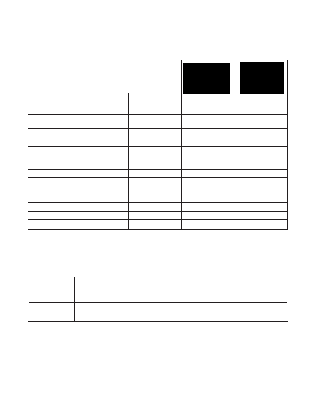
1.2 PERFORMANCE & PHYSICAL SPECIFICATIONS
SPECIFICATIONS
MODELS 396 &396VP MODELS 398 & 398VP MODEL 397 QUIK-LOC KIT
Measurements pH: 0-14 pH: 0-14 pH: 0-14 —
and Ranges ORP: -1500 to 1500 mv
Available pH GPHT hemi bulb or GPHT hemi bulb or GPHT hemi bulb —
ACCUGLASSTypes GPLR flat bulb GPLR flat bulb
Wetted Materials 316 SST, Polypropylene, Titanium, Tefzel, glass, Polypropylene, EP, glass 316 SST, EP, PEEK
EPDM, glass choice of Kalrez, Viton, or
EPDM (platinum: ORP only)
Process Connection None, use 1 in. NPT None, use 1 in. NPT None, must use Quik-Loc 1-in. MNPT
process connector, process connector, kit which includes 1 in.
PN 23166-00 or 23166-01 PN 23166-00 or 23166-01 MNPT process connection
(sold separately) (sold separately)
Temperature Range 0-100°C (32-212°F) 0-100°C (32-212°F) 0-100°C (32-212°F) —
Pressure Range- 100-1136 kPa abs 100-1825 kPa abs 100-790 kPa abs —
Hemi bulb (0-150 psig) (0-250 psig) (0-100 psig)
Pressure Range- 100-790 kPa abs 100-790 kPa abs — —
Flat bulb (0-100 psig) (0-100 psig)
Minimum Conductivity 75 µS/cm, nominal 75 µS/cm, nominal 75 µS/cm, nominal —
Preamplifier Options Remote Remote Remote
—
Weight/Shipping Weight 0.45 kg/0.9 kg (1 lb/2 lb) 0.45 kg/0.9 kg (1 lb/2 lb) 0.45 kg/0.9 kg (1 lb/2 lb) 0.45 kg/0.9 kg (1 lb/2 lb)
PERCENT LINEARITY
396, 396VP, 397, 398, 398VP 396, 396VP, 397, 398, 398VP
pH Range GPHT Hemi GPLR Hemi
0-2 pH 94% 93%
2-12 pH 99% 98%
12-13 pH 97% 95%
13-14 pH 92% —
Page 8
4
MODEL 396/396VP/397/398/398VP SECTION 1.0
DESCRIPTION AND SPECIFICATIONS
1.3 ORDERING INFORMATION
MODEL
396 TUpH INSERTION/SUBMERSION STAINLESS STEEL pH SENSOR
CODE ANALYZER/TC COMPATIBILITY (Required Selection)
50 For use with Models 1181, 1050, 1003 (3 K TC)
54 For use with Models 54/e, 1054A/B, 1055, 2700, SCL-P, 81, 2081, 3081, and 4081 (Pt-100 RTD)
CODE OPTIONAL ITEMS
62 Cable without BNC for wiring to 4081/3081/81/54 analyzers
71 Flat bulb, GPLR
396 - 54 EXAMPLE
The Model 396 pH Sensor features your selection of glass electrode type, either the
standard hemi bulb or the optional flat glass electrode combined with the coating
resistant, polypropylene reference with gel filled electrolyte. The sensor is housed
in a stainless steel body and is used with a 1 in. MNPT threaded process connector
suitable for insertion, submersion, or flow through installations. The Model 396 is
available without an integral preamplifier only and 15 ft of cable. Automatic
temperature compensation is standard 3 K Balco or PT-100 RTD.
MODEL
396VP TUpH INSERTION/SUBMERSION STAINLESS STEEL AND POLYPROPYLENE pH SENSOR (GPHT hemi bulb)
CODE ANALYZER/TC COMPATIBILITY (Required Selection)
50 For use with Models 1181, 1050, 1003 (3 K TC)
54 For use with Models 54/e, 1054A/B, 1055, 2700, SCL-P, 81, 2081, 3081, and 4081 (Pt-100 RTD)
CODE OPTIONAL OPTIONS
71 GPLR Flat bulb
396VP - 54 EXAMPLE
The Model 396VP insertion/submersion sensor is the same as Model 396 except,
instead of a cable on the back end of the sensor, it features a Variopol connector.
The watertight Variopol sensor-to-cable connector uses a mating connector cable
(ordered separately).
Page 9

MODEL 396/396VP/397/398/398VP SECTION 1.0
DESCRIPTION AND SPECIFICATIONS
The Model 398 Sensor, housed in a titanium tube and made with a Tefzel reference
junction, can be used with a 1 inch MNPT process connector (purchased separately).
The sensor is available with a hemi bulb glass pH electrode or a platinum and glass
ORP electrode and with Pt100 or 3K temperature compensation. The 398 is provided
with a standard 15 ft cable. A preamplifier must be used if the sensor is more than 15 ft
from the analyzer/transmitter. Junction box kits with preamplifiers must be ordered separately. Process connector must also be ordered separately.
CODE MEASURING ELECTRODE TYPE (Required Selection)
10 GPHT hemi glass, General Purpose High Temperature (0-14 pH)
12 ORP
13 Flat Bulb, GPLR
CODE ANALYZER/TC COMPATIBILITY (Required Selection)
50 For Models 1181 (3K TC) [no T.C. if ordered with option -12 (ORP)]
54 For Models 54/e, 1054A/B, 1055, 2700, 81, 2081, 3081, 4081, SCL-P, and Solu Cube (Pt-100 RTD)
CODE O-RING MATERIAL (Required Selection)
30 EPDM
31 Viton
32 Kalrez (recommended for applications with Chlorine Dioxide)
CODE OPTIONAL SELECTIONS (see drawings on page 4)
62 No BNC (Not Valid w/Option 50) for wiring directly to 54/e, 1055, 81, 3081, and 4081 Transmitter/Analyzers
MODEL
398 TUpH INSERTION/SUBMERSION TITANIUM pH SENSOR
398 - 10 - 32 - 54 EXAMPLE
The Model 398VP insertion/submersion sensor is the same as Model 398, except
the cable is replaced with a Variopol connector. The watertight Variopol sensor-tocable connector uses the mating connector cable (ordered separately).
CODE ANALYZER/TC COMPATIBILITY (Required Selection)
50 For Models 1181 (3K TC) [no T.C. if ordered with option -12 (ORP)]
54 For Models 54/e, 1054A/B, 1055, 2700, 81, 2081, 3081, 4081, SCL-P, and Solu Cube (Pt-100 RTD)
CODE MEASURING ELECTRODE TYPE (Required Selection)
10 GPHT hemi glass, General Purpose High Temperature (0-14 pH)
12 ORP
13 Flat
CODE O-RING MATERIAL (Required Selection)
30 EPDM
31 Viton
32 Kalrez (recommended for applications with Chlorine Dioxide)
MODEL
398VP TUpH INSERTION/SUBMERSION TITANIUM AND TEFZEL pH/ORP SENSOR
398VP - 10 - 32 - 54 EXAMPLE
5
Page 10
6
MODEL 396/396VP/397/398/398VP SECTION 1.0
DESCRIPTION AND SPECIFICATIONS
The TUpH Model 397 pH Sensor is housed in a polypropylene body and is designed
to be used with the Quik-Loc Kit. The sensor includes a large general purpose
(GPHT) glass pH electrode and a large area polypropylene reference junction with gel
filled reference electrolyte. The Model 397 is available without an integral preamplifier
only and 15 ft (4.6 m) of cable.
MODEL
397 TUpH pH SENSOR
CODE PREAMPLIFIER/CABLE (Required Selection)
02 Without integral preamplifier, 15 ft (4.6 m) cable
CODE MEASURING ELECTRODE TYPE (Required Selection)
10 GPHT, General Purpose glass (0-14 pH)
CODE ANALYZER/TC COMPATIBILITY (Required Selection)
50 For Models 1181, 1050, 1003 (3 K Balco TC)
54 For Models 1054, 1055, 54e, 81, 5081, 3081, 4081, 2081; Xmt (PT-100 RTD)
CODE OPTIONAL OPTIONS
62 Cable without BNC for wiring to 54/e, 1055, 81, 3081, 4081 analyzers, Xmt
1. Quik-Loc Mounting (required for all first time installations)
Choose one: PN
23757-00, Quik-Loc Kit: for use in 1 in. tees; insertion depth 1.4 in. (35 mm)
PN
23757-01, Quik-Loc Kit: for use in 1-1/2 in. and 2 in. tees; insertion depth 2 in. (50 mm)
2. Remote Junction Boxes (optional, recommended for sensor to analyzer distances of more than 15 ft)
Choose one: PN 23555-00 includes preamplifier for Models 54, 81, 3081, 4081
PN 23309-03 and PN 22698-02 plug-in preamplifier for Model 1181Analyzer
PN 23309-04 and PN 22698-03 plug-in preamplifier for Models 1054 series, 2054, and 2081 Analyzers
PN 23054-03 includes preamplifier for Solu Cube Model 2700
3. Extension cables (used with remote junction boxes)
Choose one: PN 23646-01, 11 conductor, shielded, prepped
PN 9200273, 11 conductor, shielded, unprepped
4. Wiring Aids
Choose one: PN 9120531 BNC splitter, used in place of option -62 or BNC coax prepping for connections to
junction box (PN 23555-00); Models 1181, 1054, 2081, 54, 81, 3081, 4081; Solu Comp (SCL-P-014);
and Model 2700 Preamplifier (PN 23054-03)
NONE: No wiring aids required for connections to Models 1054A, 1054B, 2054, or preamplifiers
PN 22698-02 or 22698-03
FOR FIRST TIME 397/QUIK-LOC INSTALLATIONS, USING THE FOLLOWING GUIDE IS RECOMMENDED:
Page 11

7
MODEL 396/396VP/397/398/398VP SECTION 1.0
DESCRIPTION AND SPECIFICATIONS
1. Process Connector Accessories (required for all first time installations with 1-inch process connection threads)
Choose one: PN 23166-00, 316 SST, 1 in. x 1 in. NPT process connector, with EPDM o-ring
PN 23166-01, Titanium, 1 in. x 1 in. NPT process connector, with EPDM o-ring
PN 9510066, Nylon, 1 in. x 1 in. NPT process connector (submersion only)
Choose one (optional process connector o-rings)
PN 9550220, Kalrez o-ring, 2-214
PN 9550099, Viton o-ring, 2-214
2. Variopol Cable (required for all first time installations) of Models 396VP and 398VP
Choose one: PN 23645-06, 15 ft cable with mating VP connector, prepped with BNC on analyzer end
PN 23645-07, 15 ft cable with mating VP connector, prepped without BNC on analyzer end*
3. Mounting Accessories (optional)
Choose one: PN 915240-03 PVC flow through tee, 3/4 in. NPT process connection
PN 915240-04 PVC flow through tee, 1 in. NPT process connection
PN 915240-05 PVC flow through tee, 1 1/2 in. NPT process connection
PN 11275-01 Sensor handrail mounting assembly
PN 2002011 1-1/2 in. CPVC Tee with 1 in. FNPT connection
PN 23728-00 Low Flow Cell, acrylic
4. Remote Junction Boxes (optional, recommended for sensor to analyzer distances of more than 15 ft)
Choose one: PN 23555-00 includes preamplifier for Models 54/e, 1055, 81, 3081, 4081
PN 23309-03 and PN 22698-02 plug-in preamplifier for Model 1181Analyzer
PN 23309-04 and PN 22698-03 plug-in preamplifier for Models 1054 series, 2054, 2081 Analyzers
PN 23054-03 includes preamplifier for Solu Cube Model 2700
5. Extension cables (used with remote junction boxes)
Choose one: PN 23646-01, 11 conductor, shielded, prepped
PN 9200273, 11 conductor, shielded, unprepped
6. Wiring Aids
Choose one: PN 9120531 BNC splitter, used in place of option -62 or BNC coax prepping for connections to junction box
(PN 23555-00); Models 54, 1055, 1054, 81,1181, 2081, 3081, 4081; SoluComp (SCL-P-014);
and Model 2700 Preamplifier (PN 23054-03)
NONE: No wiring aids required for connections to preamplifier PN 22698-02, preamplifier PN 22698-03,
or Models 1054A, 1054B, and 2054
FOR FIRST TIME 396, 396VP, 398, AND 398VP INSTALLATIONS,
ROSEMOUNT ANALYTICAL RECOMMENDS USING THE FOLLOWING GUIDE:
*Used for connections to Models 54/e, 1055, 1054, 81, 1181, 2081, 3081, 4081, and remote junction box PN 23555-00.
Page 12

8
MODEL 396/396VP/397/398/398VP SECTION 1.0
DESCRIPTION AND SPECIFICATIONS
ADDITIONAL ACCESSORIES FOR MODEL 396, 396VP, 398 AND 398VP TUpH SENSORS
PART NUMBER DESCRIPTION
33046-00 Ferrule 1 in., split 316 SS
33211-00 Adapter retrofit for PN 915240-04
9550167 EPDM O-ring for process connector (PN 23166-00)
9310100 Ferrule, 1 in. Teflon
1
9310096 Nut, Swage, 1 in. stainless steel
9550167 O-ring, 2-214 EPDM
1
Teflon is a registered trademark of E.I. du Pont de Nemours & Co.
ADDITIONAL ACCESSORIES FOR MODEL 397 TUpH SENSOR AND THE QUIK-LOC KIT
PART NUMBER DESCRIPTION
23753-00 PEEK replacement adapter for Quik-Loc kit (PN 23757-01)
23753-01 PEEK replacement adapter for Quik-Loc kit (PN 23757-00)
9160441 1 in. MNPT 316 stainless steel coupler
9160442 1 in. Plug, stainless steel
9160447 1 in. EP Gasket for coupler
2002011 1-1/2 in. CPVC Tee with 1 in. FNPT Connection
ADDITIONAL ACCESSORIES USED FOR MODELS 396, 396VP, 397, 398, AND 398VP TUpH SENSORS
PART NUMBER DESCRIPTION
22698-00 Preamplifier plug-in for J-box, 1003 compatible
22698-02 Preamplifier plug-in for J-box, 1181/1050 compatible
22698-03 Preamplifier plug-in for J-box, 1054A/B, 2054,2081 compatible
22743-01 Pt 100 preamplifier, 1181 compatible
22744-01 3K Preamplifier, 1181 compatible
23054-03 Remote J-box with preamplifier for Solu Cube Model 2700
23309-03 Remote Junction box, for preamplifier Model 1181
23309-04 Remote Junction box, for preamplifier Model 1054 Series, 2054, 2081
23555-00 Remote Junction box, with preamplifier, 54/e, 81, 3081, 4081 compatible
23557-00 Preamplifier for Junction box for Models 54/e, 1055, 81, 3081, 4081
23646-01 Extension cable 11 conductor, shielded, prepped
9200273 Extension cable11 conductor, shielded, unprepped
9210012 Buffer solution, 4.01 pH, 16 oz.
9210013 Buffer solution, 6.86 pH, 16 oz.
9210014 Buffer solution, 9.18 pH, 16 oz.
2001492 Stainless Steel Tag, Specify Marking
9200254 Cable, 4 cond., 22 AWG, 2 shielded pair
Page 13

9
2.2.1 Flow Through and Insertion Mounting for
Models 396, 396VP, 398, and 398VP. The Models 396,
396VP, 398, and 398VP Sensors can be used with a 1
inch MNPT process connector at the front of the sensor
for mounting into a 1-1/2 inch tee or the process. See
Figure 2-1 for instal lation configurations.
2.2.2 Submersion Mounting for Models 396, 396VP,
398, and 398VP. The Models 396, 396VP, 398, and
398VP Sensors also have a 1 inch MNPT process connector available for use on the back of the sensor.
Tapered pipe threads in plastic fittings tend to loosen
after installation. It is therefore recom mended that Teflon
tape be used on the threads and that the tightness of the
connection be checked frequently to assure that no loosening has occurred. To prevent rain water or condensation from running into the sensor, a weatherproof junction box is recommended (see Figure 2-4). The sensor
cable must be run through a protective conduit for isolation from electrical interference or physical abuse from
the process. The sensor should be installed within 80° of
vertical, with the electrode facing down. The sensor’s
cable should not be run with power or control wiring.
2.2.3 Quik-Loc Mounting for Model 397. The QuikLoc mounting is used with the Model 397 TUpH sensor only.
SAFETY WARNING
It is recommended that a thermometer,
drain valve to relieve pressure and
pres-sure gauge be inserted near the
Quik-Loc assembly (see Figure 2-5).
WARNING
Once the Quik-Loc unit is installed the operator should wait for the process to cool to a
safe temperature, use the pressure drain
valve to relieve all process pressure and
observe the pressure on the pressure gauge
for proper removal of the sensor without
spray or bodily injury. The Quik-Loc kit used
with the 397 TUpH sensor is not recommended for use with hazardous, corrosive,
or strong oxidizing chemicals due to a risk of
spray or bodily injury.
MODEL 396/396VP/397/398/398VP SECTION 2.0
INSTALLATION
2.1 UNPACKING AND INSPECTION. Inspect the out-
side of the carton for any damage. If damage is detected, contact the carrier immediately. Inspect the instrument and hardware. Make sure all the items in the packing list are present and in good condition. Notify the factory if any part is missing. If the sensor appears to be in
satisfactory condition, proceed to Section 2.2, Mounting.
NOTE
Save the original packing cartons and materials as most carriers require proof of damage due to mishandling, etc. Also, if it is necessary to return the instrument to the factory, you must pack the instrument in the same
manner as it was received. Refer to Section
6 for return instructions. If the sensor is to be
stored, the vinyl boot should be filled with pH
buffer solution and replaced on sensor tip
until ready to use.
WARNING
Glass electrode must be wetted at all times (in
storage and in line) to maximize sensor life.
2.2 MOUNTING. Each sensor has been designed to
be located in industrial process environments.
Temperature and pressure limitations must not
be exceeded at any time. A caution or warning label
regarding this matter is attached to each sensor. For
insertion, transfer the label as shown on label instructions. See Figure 2-2. For submersion applications, first
note limits then remove and discard label.
NOTE
Before mounting the sensor, shake down
the sensor to remove any air bubbles that
may be present at the tip of the pH glass
bulb. In most cases, the pH sensor can simply be installed as shipped and readings
with an accuracy of ±0.6 pH may be
obtained. To obtain greater accuracy or to
verify proper operation, the sensor must be
calibrated as a loop with its compatible analyzer or transmitter.
SECTION 2.0
INSTALLATION
Page 14

10
MODEL 396/396VP/397/398/398VP SECTION 2.0
INSTALLATION
Wrap the pipe threads of the Twin-Kam Kamloc coupler
with Teflon tape before placing it into the process pipe. The
coupler can be connected to any 1 in. process connection
and must be mounted within 80° of vertical, with the electrode facing down. Once the coupler is in place, the
adapter should be positioned onto the back end of the sensor. (See Figure 2-5) Remove the parafilm wrapping from
the two 0-rings on the sensor, grease the o-rings with the
lube provided, and feed the sensor cable through the
adapter. Once the adapter is slipped over the sensor’s
back end, the retaining ring (which is included with every
397 sensor) should be installed on the black, grooved,
back end of the sensor body. The retaining ring secures
the sensor into the adapter. The adapter/sensor assembly
is now ready to be inserted into the coupler. With both
arms of the coupler in the released position, insert the
adapter/sensor assembly into the coupler.
NOTE
The adapter can not be inserted completely or
properly unless both arms are in the fully
released position (see Figure 2-5).
Once the adapter has been properly placed in the coupler,
both arms should be positioned in the locked position. A SurLoc
™ 1
spring arm has been provided on one arm so that the
“arm cannot be opened until the spring is released.”
2
NOTE
The sensor may obstruct flow through smaller pipes.
Once the arms of the coupler have been locked in position,
use tamper-evident safety wire on the metal rings of the
Twin-Kam arms to prevent unauthorized and/or untrained
personnel from using the Quik-Loc unit.
SAFETY WARNING
It is the responsibility of each company using the Quik-Loc Kit/ 397
TUpH Sensor to train personnel of
the injury risks associated with
using a quick-release coupler that is
placed in a hot or pressurized
process.
The Quik-Loc unit should be used only within the pressure
and temperature limits stated for the Model 397 sensor in
Section 1.2.
FIGURE 2-1. Recommended Flow Through and Insertion Installation
For Models 396, 396VP, 398 and 398VP
1-1/2 inch Pipe Tee (PN 2002011) with 1 inch threaded connections.
DWG. NO. REV.
40039609 D
Page 15

11
MODEL 396/396VP/397/398/398VP SECTION 2.0
INSTALLATION
FIGURE 2-2. Dimensional Drawing For Models 396 and 398
DWG. NO. REV.
40039601 J
MILLIMETER
INCH
Page 16

12
MODEL 396/396VP/397/398/398VP SECTION 2.0
INSTALLATION
INCH
MILLIMETER
Metal Process Connector PN 23166-xx
(xx = 00 for 316 SST and xx = 01 for titanium) can be used for insertion or submersion mounting of Models 396VP or
398VP sensors in 1-inch fittings.
The metal process connector gives the sensor various insertions depths, depending on where the
user locates the compression fitting. Also the
threads can be switched to face the cable end of
the sensor for connection to submersion pipes.
FIGURE 2-3. Dimensional Drawings: Model 396VP and 398VP Shown with Process Connector
Page 17

13
DWG. NO. REV.
40039602 D
MILLIMETER
INCH
DWG. NO. REV.
40039603 C
DWG. NO. REV.
40039604 D
MODEL 396/396VP/397/398/398VP SECTION 2.0
INSTALLATION
P.N. 23166-00, 23166-01,
OR 9510066
FIGURE 2-4. Submersion Installations for Models 396, 396VP, 398, and 398VP.
Page 18

14
MODEL 396/396VP/397/398/398VP SECTION 2.0
INSTALLATION
FIGURE 2-5. Dimensional Drawings For Model 397 in the Quik-Loc Unit
DWG. NO. REV.
40039701 C
MILLIMETER
INCH
DWG. NO. REV.
40039704 B
NOTE: The EP gasket (see drawing #40039702)
provided with the coupler should be periodically
inspected. If gasket shows signs of corrosion,
replacement will be necessary to ensure a proper
and secure seal between the coupler and adapter.
DWG. NO. REV.
40039702 C
Page 19

15
MODEL 396/396VP/397/398/398VP SECTION 2.0
INSTALLATION
2.3 ELECTRICAL INSTALLATION.
The Models 396, 396VP, 397, 398, and 398VP are for use
with a remote preamplifier. Each sensor comes with either a
special 15 ft low noise coax cable or a Variopol (VP) connector, which is used with a mating Variopol cable. The
cable should be handled carefully, and kept dry and free of
corrosive chemicals at all times. Extreme care should be
used to prevent the cable from being twisted, damaged or
scraped by rough, sharp edges or surfaces. Please refer to
Figures 2-7 thru 2-18 for wiring Models 396, 397, and 398.
Please refer to Figures 2-19 thru 2-36 for wiring Models
396VP and 398VP.
DANGER
DO NOT CONNECT SENSOR CABLE TO POWER
LINES. SERIOUS INJURY MAY RESULT
.
FIGURE 2-7. Models 396, 397, and 398 Standard Wiring
Option used with Models 1054A, 1054B, 2054, and
Preamplifiers PN 22698-02 and 22698-03.
FIGURE 2-8. Models 396, 397, and 398 Option -62 for
Wiring to Models 1054, 1181, 2081, 54, 81, 3081, 4081,
SoluComp, and 2700 Preamplifier (PN 23054-03). Also for
use with remote Junction Box PN 23555-00.
FIGURE 2-6. Recommended Flow-Through and Insertion Installation For Model 397
DWG. NO. REV.
40039703 B
NOTE
Remove electrical tape or shrink sleeve from gray reference wire before connecting wire to terminal.
Page 20

16
MODEL 396/396VP/397/398/398VP SECTION 2.0
INSTALLATION
DWG. NO. REV.
40039610 D
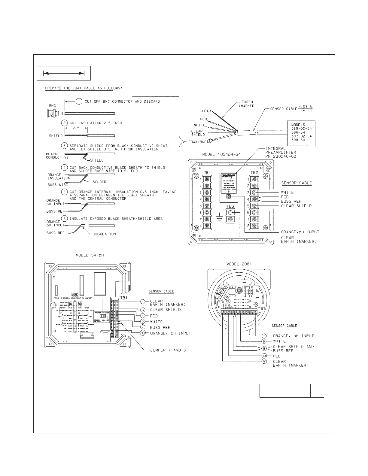
FIGURE 2-9. Wiring Details For Model 396-54 (50), 397-54 (50), and 398-54 (50).
For Use With Junction Box (PN 23309-04 (03)) and Remote Preamplifier
DWG. NO. REV.
40039706 B
Page 21

17
DWG. NO. REV.
40038920 G
MILLIMETER
INCH
MODEL 396/396VP/397/398/398VP SECTION 2.0
INSTALLATION
FIGURE 2-10. Wiring Details for Model 396-54, 397-54, and 398-54 (Pt-100 RTD). For Use With
Junction Box (PN 23555-00) and Remote Preamplifier.
Page 22

18
MODEL 396/396VP/397/398/398VP SECTION 2.0
INSTALLATION
FIGURE 2-11. Wiring Details For Models 396, 397, and 398. For Use With Model 1181 pH.
DWG. NO. REV.
40039607 D
Page 23

19
FIGURE 2-12. Wiring Details For Models 396-54, 397-54, and 398-54.
For Use With Models 1054ApH-54, 1054BpH-54, and 2054pH-54
DWG. NO. REV.
40039606 D
MILLIMETER
INCH
MODEL 396/396VP/397/398/398VP SECTION 2.0
INSTALLATION
Page 24
20
MODEL 396/396VP/397/398/398VP SECTION 2.0
INSTALLATION
FIGURE 2-13. Wiring Details For Models 396-54, 397-54, and 398-54.
For Use With Models 2081 pH-05 and 1054 pH-54
DWG. NO. REV.
40039608 D
MILLIMETER
INCH
Page 25

21
DWG. NO. REV.
40039605 F
MILLIMETER
INCH
MODEL 396/396VP/397/398/398VP SECTION 2.0
INSTALLATION
FIGURE 2-14. Wiring Details For Models 396-54 , 397-54, and 398-54.
For Use With Models 54, 54e, 81, 3081, 4081, and 5081.
Page 26

22
MODEL 396/396VP/397/398/398VP SECTION 2.0
INSTALLATION
FIGURE 2-15. Wiring Details For Models 396-54 , 397-54, and 398-54.
For Use With SoluComp Model SCL-P-014.
MILLIMETER
INCH
DWG. NO. REV.
40039611 D
Page 27

23
FIGURE 2-16. Wiring Models 396-54, 397-54, and 398-54 to Model 2700 Preamplifier (PN 23054-03).
MODEL 396/396VP/397/398/398VP SECTION 2.0
INSTALLATION
FIGURE 2-17. Wiring Models 396-( )-54-62-(71), 397-02-10-54-62, and 398-( )-54-62
to Model 1055-01-10-22-32
FIGURE 2-18. Wiring Models 396-54-62, 397-02-54-62, and 398-54-62 to Model 1055-22-32
Page 28

24
See below for wire functions for Models 396VP and 398VP. The Variopol connector cable part numbers are PN 2364506 (with BNC) and PN 23645-07.
FIGURE 2-19. Wire Functions and Pin Connections
for Variopol connector cable
PN 23645-06 (with BNC) PN 23645-07
FIGURE 2-21. Wiring Model 396VP and 398VP to
Model 81
FIGURE 2-20. Wiring Model 396VP
and 398VP to Model 81 through a
Remote Junction Box
FIGURE 2-22. Wiring Model 396VP and 398VP to
Model 1181
MODEL 396/396VP/397/398/398VP SECTION 2.0
INSTALLATION
Page 29

FIGURE 2-24. Wiring Model
396VP and 398VP to Model 2081
FIGURE 2-25. Wiring Model
396VP and 398VP to Model 3081
and 4081
FIGURE 2-27. Wiring Model
396VP and 398VP to Model 3081,
4081, and 5081 through a
Remote Junction Box
FIGURE 2-26. Wiring Model
396VP and 398VP to Model 2081
through a Remote Junction Box
FIGURE 2-23. Wiring Model 396VP
and 398VP to Model 1181,
1050/1060, and 1003/1023 through
a Remote Junction Box
MODEL 396/396VP/397/398/398VP SECTION 2.0
INSTALLATION
25
Page 30

26
FIGURE 2-28. Wiring Model 396VP and 398VP to
Model 1054
FIGURE 2-30. Wiring Model 396VP and 398VP to
Model 1054 through a Remote Junction Box
FIGURE 2-29. Wiring Model 396VP and 398VP to
Models 1054A, 1054B, and 2054
FIGURE 2-31. Wiring Model 396VP and 398VP
to Models 1054A, 1054B, and 2054 through a
Remote Junction Box
MODEL 396/396VP/397/398/398VP SECTION 2.0
INSTALLATION
Page 31

FIGURE 2-33. Wiring Model 396VP/398VP to Models 54/54e
FIGURE 2-32. Wiring Model 396VP and 398VP to Models 54 and 54e through a Remote Junction Box
FIGURE 2-35. Wiring Model
396VP and 398VP to Model 2700
FIGURE 2-34. Wiring Model 396VP and
398VP to Model SCL-(P/Q)
MODEL 396/396VP/397/398/398VP SECTION 2.0
INSTALLATION
27
Page 32

28
MODEL 396/396VP/397/398/398VP SECTION 2.0
INSTALLATION
FIGURE 2-36. Wiring Model 396VP-54 to Model 1055-22-32
Page 33

MODEL 396/396VP/397/398/398VP SECTION 2.0
INSTALLATION
29
FIGURE 2-37. Wiring Models 396-54-6, 397-54-62, & 398-54-62 to Model Xmt-P-XX-10
FIGURE 2-38. Wiring Models 396VP & 398VP to Model Xmt-P-XX-10
XMT -P XX -10
396VP
398VP
Page 34

30
MODEL 396/396VP/397/398/398VP SECTION 2.0
INSTALLATION
FIGURE 2-39. Wiring Models 396/397/398 to Model 5081-P
FIGURE 2-40. Wiring Models 396-54-62/398-54-62 to Model 1055-01-10-22-32
Model 398-54-62
Model 396-54-62
1055 -01 -10 -22 -32
Page 35

MODEL 396/396VP/397/398/398VP SECTION 3.0
START UP AND CALIBRATION
SECTION 3.0
START UP AND CALIBRATION
3.1 SENSOR PREPARATION.
Shake down the sensor to remove any air bubbles
that may be present at the tip of the pH glass bulb. In
most cases, the pH sensor can simply be installed as
shipped and readings with an accuracy of ±0.6 pH
may be obtained. To obtain greater accuracy or to
verify proper operation, the sensor must be calibrated
as a loop with its compatible analyzer or transmitter.
3.2 CALIBRATION USING BUFFER
SOLUTIONS OR GRAB SAMPLES.
The pH sensor-analyzer/ transmitter loop may be
calibrated by submersing the sensor in a buffer solution (standard solutions of known pH values) or in a
process grab sample whose pH value maybe
checked by a calibrated laboratory or portable pH
meter.
Please refer to the analyzer's or the transmitters
respective instruction manuals for proper calibration procedures.
31
Page 36

32
MODEL 396/396VP/397/398/398VP SECTION 4.0
MAINTENANCE
4.0 MAINTENANCE. The Model 396, 396VP, 397,
398, and 398VP Sensors are disposable type sensors
and therefore require minimum maintenance. Every
sensor should be kept clean and free of debris and
sediment at all times. The frequency of cleaning by
wiping or brushing with a soft cloth or brush is determined by the nature of the solution being measured.
The sensor should be removed from the process periodically and checked in buffer solutions.
SAFETY WARNING
SENSOR IS IN PRESSURIZED SYSTEM!
May cause spray and bodily injury. Before
removing sensor, be absolutely certain that
the process pressure is reduced to 0 psig
and the process temperature is lowered to a
safe level.
If the sensor will not calibrate, refer to your analyzer/
transmitter instruction manual for proper test procedures. If it is determined that the sensor has failed, it
should be discarded and replaced.
4.1 ELECTRODE CLEANING. If the electrode is coated or dirty, clean as follows:
1. Remove the sensor from process.
SAFETY WARNING
SENSOR IS IN PRESSURIZED SYSTEM
may cause spray and bodily injury.
Before removing sensor, be absolutely certain that the process pressure is reduced to
0 psig and the process temperature is lowered to a safe level.
2. Wipe the glass bulb with a soft, clean, lint free cloth
or tissue. If this does not remove the dirt or coating,
go to Step 3. (Detergents clean oil and grease;
acids remove scale.)
3. Wash the glass bulb in a strong detergent solution
and rinse it in clean water. If this does not clean the
glass bulb, go to Step 4.
CAUTION
The solution used during the following check is an acid
and should be handled with care. Follow the directions
of the acid manufacturer. Wear the proper protective
equipment. Do not let the solution come in contact with
skin or clothing. If contact with skin is made, immediately rinse with clean water.
SECTION 4.0
MAINTENANCE
4. Wash the glass bulb in a dilute 5% hydro chloric acid
solution and rinse with clean water. Soaking the
sensor overnight in the acid solution can improve
cleaning action.
NOTE
Erroneous pH results may occur immedi ately after acid soak, due to reference
junction potential build-up.
Replace the sensor if cleaning does not
restore sensor operation.
4.2 AUTOMATIC TEMPERATURE COMPENSATOR.
The temperature compensator element is temp erature
sensitive and can be checked with an ohmmeter.
Resistance increases with temperature.
The 3K element will read 3000 ohms ±1% at 25°C (77°F)
and a Pt-100 will read 110 ohms. Resistance varies with
temperature for a 3K and Pt-100 element and can be
determined according to Table 4-2 or the following formula:
RT=Ro[l+R1(T-20)]
Where RT= Resistance
T = Temperature in °C
Refer to Table 4-1 for Roand R1values
TABLE 4-1. Roand R1Values for
Temperature Compensation Elements
Temperature °C Resistance (Ohms) ±1%
3K PT-100
0 2670 100.0
10 2802 103.8
20 2934 107.7
25 3000 109.6
30 3066 111.5
40 3198 115.4
50 3330 119.2
60 3462 123.1
70 3594 126.9
80 3726 130.8
90 3858 134.6
100 3990 138.5
Temperature
Compensation Element
R
o
R
1
3K 2934 .0045
PT-100 107.7 .00385
TABLE 4-2.Temperature vs Resistance
of Auto T.C. Elements
Page 37

33
MODEL 396/396VP/397/398/398VP SECTION 5.0
TROUBLESHOOTING
Trouble Probable Cause Remedy
Meter reads off scale. (Display T.C. element shorted. Check T.C. element as instructed
reads overrange.) in Section 4.2 and
replace sensor if defective.
Sensor not in process or sample Make sure sensor is in process with
stream is low. sufficient sample stream (refer to
Section 2.0 for installation details).
Open glass electrode. Replace sensor.
Reference element open - no contact.
Replace sensor.
Display reads between 3 and 6 pH Electrode cracked. Replace sensor.
regardless of actual pH of solution
or sample.
Meter or display indication swings T.C. element shorted. Check T.C. element as instructed
or jumps widely in AUTO T.C. Mode. in Section 4.2 and replace
sensor if defective.
Span between buffers extremely T.C. element open. Check T.C. element as instructed
short in AUTO T.C. Mode. in Section 4.2 and replace sensor
if defective.
Sluggish or slow meter indication Electrode coated. Clean sensor as instructed in
for real changes in pH level. Sections 4.1 Replace sensor
if cracked.
Electrode at end of life. Replace sensor.
Transmitter cannot be standardized. Electrode coated or cracked. Clean sensor as instructed in
Sections 4.1. Replace sensor
if cracked.
Transmitter short spans between Electrode at end of life, due to Replace sensor.
two different buffer values. old glass or high temperature
exposure.
Coated glass. Clean sensor as instructed in
Section 4.1. Replace sensor
if cracked.
TABLE 5-1. Troubleshooting
SECTION 5.0
TROUBLESHOOTING
Page 38

34
MODEL 396/396VP/397/398/398VP SECTION 6.0
RETURN OF MATERIAL
SECTION 6.0
RETURN OF MATERIAL
6.1 GENERAL.
To expedite the repair and return of instruments, proper
communication between the customer and the factory
is important. Before returning a product for repair, call
1-949-757-8500 for a Return Materials Authorization
(RMA) number.
6.2 WARRANTY REPAIR.
The following is the procedure for returning instruments still under warranty:
1. Call Rosemount Analytical for authorization.
2. To verify warranty, supply the factory sales order
number or the original purchase order number. In
the case of individual parts or sub-assemblies, the
serial number on the unit must be supplied.
3. Carefully package the materials and enclose your
“Letter of Transmittal” (see Warranty). If possible,
pack the materials in the same manner as they
were received.
4. Send the package prepaid to:
Rosemount Analytical Inc., Uniloc Division
Uniloc Division
2400 Barranca Parkway
Irvine, CA 92606
Attn: Factory Repair
RMA No. ____________
Mark the package: Returned for Repair
Model No. ____
6.3 NON-WARRANTY REPAIR.
The following is the procedure for returning for repair
instruments that are no longer under warranty:
1. Call Rosemount Analytical for authorization.
2. Supply the purchase order number, and make
sure to provide the name and telephone number
of the individual to be contacted should additional
information be needed.
3. Do Steps 3 and 4 of Section 6.2.
NOTE
Consult the factory for additional information regarding service or repair.
Page 39

WARRANTY
Seller warrants that the firmware will execute the programming instructions provided by Seller, and that the Goods manufactured
or Services provided by Seller will be free from defects in materials or workmanship under normal use and care until the expiration of the applicable warranty period. Goods are warranted for twelve (12) months from the date of initial installation or eighteen
(18) months from the date of shipment by Seller, whichever period expires first. Consumables, such as glass electrodes,
membranes, liquid junctions, electrolyte, o-rings, catalytic beads, etc., and Services are warranted for a period of 90
days from the date of shipment or provision.
Products purchased by Seller from a third party for resale to Buyer ("Resale Products") shall carry only the warranty extended by
the original manufacturer. Buyer agrees that Seller has no liability for Resale Products beyond making a reasonable commercial
effort to arrange for procurement and shipping of the Resale Products.
If Buyer discovers any warranty defects and notifies Seller thereof in writing during the applicable warranty period, Seller shall, at
its option, promptly correct any errors that are found by Seller in the firmware or Services, or repair or replace F.O.B. point of manufacture that portion of the Goods or firmware found by Seller to be defective, or refund the purchase price of the defective portion of the Goods/Services.
All replacements or repairs necessitated by inadequate maintenance, normal wear and usage, unsuitable power sources, unsuitable environmental conditions, accident, misuse, improper installation, modification, repair, storage or handling, or any other
cause not the fault of Seller are not covered by this limited warranty, and shall be at Buyer's expense. Seller shall not be obligated to pay any costs or charges incurred by Buyer or any other party except as may be agreed upon in writing in advance by
an authorized Seller representative. All costs of dismantling, reinstallation and freight and the time and expenses of Seller's personnel for site travel and diagnosis under this warranty clause shall be borne by Buyer unless accepted in writing by Seller.
Goods repaired and parts replaced during the warranty period shall be in warranty for the remainder of the original warranty period or ninety (90) days, whichever is longer. This limited warranty is the only warranty made by Seller and can be amended only
in a writing signed by an authorized representative of Seller. Except as otherwise expressly provided in the Agreement, THERE
ARE NO REPRESENTATIONS OR WARRANTIES OF ANY KIND, EXPRESS OR IMPLIED, AS TO MERCHANTABILITY, FITNESS FOR PARTICULAR PURPOSE, OR ANY OTHER MATTER WITH RESPECT TO ANY OF THE GOODS OR SERVICES.
RETURN OF MATERIAL
Material returned for repair, whether in or out of warranty, should be shipped prepaid to:
Emerson Process Management
Liquid Division
2400 Barranca Parkway
Irvine, CA 92606
The shipping container should be marked:
Return for Repair
Model
_______________________________
The returned material should be accompanied by a letter of transmittal which should include the following information (make a
copy of the "Return of Materials Request" found on the last page of the Manual and provide the following thereon):
1. Location type of service, and length of time of service of the device.
2. Description of the faulty operation of the device and the circumstances of the failure.
3. Name and telephone number of the person to contact if there are questions about the returned material.
4. Statement as to whether warranty or non-warranty service is requested.
5. Complete shipping instructions for return of the material.
Adherence to these procedures will expedite handling of the returned material and will prevent unnecessary additional charges
for inspection and testing to determine the problem with the device.
If the material is returned for out-of-warranty repairs, a purchase order for repairs should be enclosed.
Page 40

Credit Cards for U.S. Purchases Only.
The right people,
the right answers,
right now.
ON-LINE ORDERING NOW AVAILABLE ON OUR WEB SITE
http://www.raihome.com
Specifications subject to change without notice.
Emerson Process Management
2400 Barranca Parkway
Irvine, CA 92606 USA
Tel: (949) 757-8500
Fax: (949) 474-7250
http://www.raihome.com
© Rosemount Analytical Inc. 2010
8
 Loading...