

Page 1
pH/ORP Sensor
Instruction Manual
PN 51-381/rev.D
October 2007
Model 381
Page 2
CAUTION
SENSOR/PROCESS
APPLICATION COMPATIBILITY
The wetted sensor materials may not
be compatible with process com position and operating conditions.
Application compat ibility is entirely the
responsibility of the user.
DANGER
HAZARDOUS AREA INSTALLATION
Installations near flammable liquids or in hazardous area locations must be carefully evaluated by qualified on site safety personnel.
This sensor is not
Intrinsically Safe or
Explosion Proof.
To secure and maintain an intrinsically safe
installation, the certified safety barrier,
transmitter, and sensor combi nation must
be used. The installation system must comply with the governing approval agency (FM,
CSA or BASEEFA/CENELEC) hazardous
area classification requirements. Consult
your analyzer/transmitter instruc tion manual
for details.
Proper installation, operation and servicing
of this sensor in a Hazardous Area Instal lation is entirely the responsibility of the user.
ESSENTIAL INSTRUCTIONS
READ THIS PAGE BEFORE
PROCEEDING!
Rosemount Analytical designs, manufactures, and tests its
products to meet many national and international standards. Because these instruments are sophisticated technical products, you must properly install, use, and maintain
them to ensure they continue to operate within their normal
specifications. The following instructions must be adhered
to and integrated into your safety program when installing,
using, and maintaining Rosemount Analytical products.
Failure to follow the proper instructions may cause any one
of the following situations to occur: Loss of life; personal
injury; property damage; damage to this instrument; and
warranty invalidation.
• Read all instructions prior to installing, operating, and
servicing the product. If this Instruction Manual is not the
correct manual, telephone 1-800-654-7768 and the
requested manual will be provided. Save this Instruction
Manual for future reference.
• If you do not understand any of the instructions, contact
your Rosemount representative for clarification.
• Follow all warnings, cautions, and instructions marked on
and supplied with the product.
• Inform and educate your personnel in the proper installation, operation, and maintenance of the product.
• Install your equipment as specified in the Installation
Instructions of the appropriate Instruction Manual and
per applicable local and national codes. Connect all
products to the proper electrical and pressure sources.
• To ensure proper performance, use qualified personnel
to install, operate, update, program, and maintain the
product.
• When replacement parts are required, ensure that qualified people use replacement parts specified by
Rosemount. Unauthorized parts and procedures can
affect the product’s performance and place the safe
operation of your process at risk. Look alike substitutions
may result in fire, electrical hazards, or improper operation.
• Ensure that all equipment doors are closed and protective covers are in place, except when maintenance is
being performed by qualified persons, to prevent electrical shock and personal injury.
Emerson Process Management
Rosemount Analytical Inc.
2400 Barranca Parkway
Irvine, CA 92606 USA
Tel: (949) 757-8500
Fax: (949) 474-7250
http://www.RAuniloc.com
© Rosemount Analytical Inc. 2001
Page 3

MODEL 381 pH/ORP TABLE OF CONTENTS
MODEL 381 pH/ORP SENSOR
TABLE OF CONTENTS
Section Title Page
1.0 DESCRIPTION AND SPECIFICATIONS........................................................... 1
1.1 Features and Applications................................................................................. 1
1.2 Sensor Specifications........................................................................................ 2
1.3 Ordering Information ......................................................................................... 3
2.0 INSTALLATION ................................................................................................. 5
2.1 Installation ......................................................................................................... 5
2.2 Submersion Installation (Code 02).................................................................... 5
2.3 Insertion Installation (Code 00) ......................................................................... 7
2.4 Flow Through Installation (Code 03) ................................................................. 7
2.5 Flow Powered Cleaner Installation (Code 04)................................................... 7
2.6 Wiring ................................................................................................................ 7
2.7 Start-Up and Calibration.................................................................................... 14
2.8 Model 381 pH and pHE..................................................................................... 14
2.9 Model 381 ORP................................................................................................. 14
3.0 MAINTENANCE ................................................................................................ 15
3.1 General ............................................................................................................. 15
3.2 Periodic Maintenance........................................................................................ 15
3.3 Troubleshooting................................................................................................. 16
3.4 Preamplifier Troubleshooting ............................................................................ 18
3.5 T.C. Element Maintenance................................................................................ 18
4.0 ULTRASONIC CLEANER ................................................................................. 21
4.1 Ultrasonic Cleaner............................................................................................. 21
4.2 Specifications .................................................................................................... 21
4.3 Installation ......................................................................................................... 21
4.4 Operation .......................................................................................................... 22
4.5 Maintenance...................................................................................................... 22
4.6 Replacement Parts............................................................................................ 22
5.0 RETURN OF MATERIAL................................................................................... 25
LIST OF TABLES
Table No. Title Page
2-1 ORP of Saturated Quinhydrone Solutions (in Millivolts).................................... 14
3-1 Troubleshooting................................................................................................. 17
3-2 Temperature vs. Resistance of Auto TC Element.............................................. 18
3-3 Ro& R1Values for Temperature Compensation Elements .............................. 18
3-4 Model 381 Spare Parts...................................................................................... 19
3-5 Accessories....................................................................................................... 19
i
Page 4

MODEL 381 pH/ORP TABLE OF CONTENTS
MODEL 381 pH/ORP SENSOR
LIST OF FIGURES
Figure No. Title Page
1-1 Dimensional Drawing ........................................................................................ 3
1-2 Mounting Drawing ............................................................................................. 3
2-1 Model 381 Sensor Component Locator Diagram.............................................. 6
2-2 Submersion Installation Diagram ...................................................................... 8
2-3 Insertion Installation Diagram............................................................................ 8
2-4 Flow Through Installation Diagram (Code 03 or 04) ......................................... 9
2-5 Installation Details Low Flow Conditions Model 381 (Code 03-04)................... 9
2-6 Retro-Fit Kit and Code-04 Flow Powered Cleaner, Model 381 ......................... 10
2-7 Flow Through Diagram and Wiring (Code 03 or 04) ......................................... 11
2-8 Remote Junction Box with Internal Preamp...................................................... 12
2-9 Wiring with Weatherproof or Div. 2 (Code 2) Junction Box .............................. 13
4-1 Model 381 Ultrasonic Cleaner and Wiring......................................................... 23
4-2 Dimensional and Component Locator Ultrasonic Generator............................. 24
ii
About This Document
This manual contains instructions for installation and operation of the Model 381
pH/ORP Sensor.
The following list provides notes concerning all revisions of this document.
Rev. Level
Date Notes
A 6/94-1/00 This is the initial release of the product manual. The manual
has been reformatted to reflect the Emerson documentation
style and updated to reflect any changes in the product offering.
B 5/02 Updated multiple drawings throughout manual.
C 3/05 Updates
D 10/07 Updated page 3 code 00 insertion is no longer available.
Page 5

1
• MOLDED POLYETHERSULFONE (PES) BODY provides compatibility with a variety of
processes.
• MODULAR DESIGN facilitates maintenance by eliminating terminal and mounting brackets
and extraneous hardware.
• INTEGRAL PREAMPLIFIER provides reliable signal transmission.
• DOUBLE JUNCTION, GEL-FILLED, REFERENCE CELL provides high temperature performance, extended service life, and resists the effects of pumping, dilution and contamination.
• OPTIONAL FLOW-POWERED OR ULTRASONIC CLEANING provides trouble-free service in difficult applications.
1.1 FEATURES AND APPLICATIONS
The Model 381 Sensor measures the pH or the
Oxidation Reduction Potential (ORP) of aqueous solutions in pipelines, open tanks or ponds. The sensor is
used in most industrial applications including SO
2
scrubbers, rinse tanks, plating baths, reverse osmosis
units, and water and waste treatment plants.
The sensor is housed in a molded PES body and has
two O-ring seals with breach lock threads which
secure the PES cover. This provides a waterproof
union for long operating life and easy removal for routine maintenance.
The modular body design eliminates the need for
internal mounting brackets, terminal brackets and
screws. All components are screw-type or plug-inplace, allowing for fast simple service.
The integral preamplifier amplifies the high impedance glass electrode signal at the sensor, providing a
transmission capability of up to three miles. The
Rosemount Analytical Inc. method of preamplification
has become the industry standard for reliable pH
measurement. In submersion applications at temperatures greater than 80°C, the preamplifier must be
located in a remote junction box.
A standard feature of the Model 381 is the double
junction, gel-filled reference cell which reduces the
need for special applications engineering where
unknown reference cell contamination, such as sulfides, may exist. The gel solution maintains its viscosi-
ty at high temperatures, and resists the effect of
pumping and dilution, resulting in an extended service
life. A choice of wood (Code 20) or ceramic (Code 21)
liquid junction is available to provide resistance to
fouling and subsequent loss of electrical contact
between the reference electrode and process fluid.
In flow applications where crystalline or viscous coatings, such as calcium carbonate or petroleum oils,
may coat the electrode surfaces and impede the sensor's performance, the flow-powered cleaning option
(Code 04) may be used. A specially designed flow
chamber directs the process fluid in a circular path
carrying three Teflon1balls which clean the electrode
surface, physically preventing accumulation of coating
materials. Flow-powered cleaning is suitable for all
hazardous area applications.
In submersion (Code 02) applications, the ultrasonic
cleaning option may be specified. This assembly
includes the ultrasonic transducer and generator,
mounting hardware, and 20 ft. of interconnection
cable. Ultrasonic cleaning is not suitable for hazardous area applications.
The Model 381 is compatible with all Rosemount
Analytical pH/ORP analyzers. For use with the
1054/2054 Series, 2081 and other pH analyzers
which utilize a PT-100 automatic temperature compensator order the Model 381 pHE.
MODEL 381 pH/ORP SECTION 1.0
DESCRIPTION AND SPECIFICATIONS
SECTION 1.0
DESCRIPTION AND SPECIFICATIONS
1
Teflon is a registered trademark of E.I. du Pont de Nemours & Co.
Page 6
2
MODEL 381 pH/ORP SECTION 1.0
DESCRIPTION AND SPECIFICATIONS
1.2 SENSOR SPECIFICATIONS
Materials of Construction:
Body, Cover and Flow Cell: Polyethersulfone (PES).
O-Rings: Viton
2.
Measuring Electrode: Glass (and platinum for
Model 381 ORP).
Liquid Junction: Kynar3/wood (Code 20) or
Kynar/ceramic (Code 21).
Process Connections: Submersion: 3/4 inch MNPT.
Insertion: 2 inch MNPT.
Flow Through:3/4 inch MNPT.
Dimensions: (see Figure 1-1).
Measuring Range: pH 0-14
ORP –1500mV to +1500mV
Temperature Compensation: (Model 381 pH only,
not required for Model 381 ORP).
Automatic, 0 to 100°C (32 to 212°F).
Pressure Rating: 790 kPa abs at 100°C
(100 psig at 212°F)
Cable: Four-conductor, 22 GA, each (0.64 mm dia.),
with common shield.
Weight/Shipping Weight: 1.0 kg/1.7 kg (2.2 lb./ 3.7 lb.).
2
Viton is a registered trademark of E.I. du Pont de Nemours & Co.
3
Kynar is a trademark of Elf Atochem North America, Inc.
HANDRAIL MOUNTING ACCESSORY HANDRAIL MOUNTING ACCESSORY
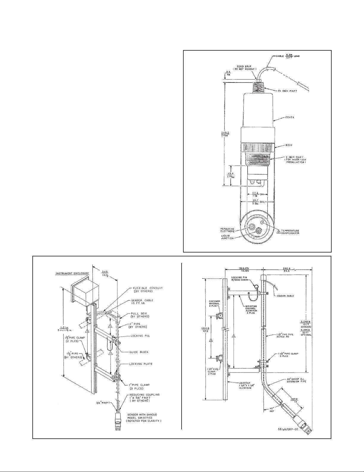
FIGURE 1-2. Mounting Drawing
FIGURE 1-1. Dimensional Drawing
PN 1000856 PN 11275-00
Page 7
3
1.3 ORDERING INFORMATION Model pH/ORP Sensor is housed in a PES body suitable for insertion, submer-
sion or flow through installation. The sensor includes an integral preamplifier, measuring electrode, double junction gel-filled reference cell, automatic temperature compensation for pH, and a choice of two cable lengths of
either 15 ft. or 50 ft. (4.5 or 15.2 m).
MODEL 381 INSERTION, SUBMERSION, FLOW THROUGH SENSOR
CODE FUNCTION
pH Requires Code 30
ORP Requires Code 32 (not for use with 1054/1054A ORP Series)
pHE Requires Code 31 (for use with 1054/1054A/2054 Series and 2081)
381 pH 00 10 20 30 40 51 EXAMPLE
MODEL 381 pH/ORP SECTION 1.0
DESCRIPTION AND SPECIFICATIONS
CODE MEASURING ELECTRODE
10 General purpose pH
11 High pH Electrode, requires Code 21. For sodium concentrations greater than 1% or
continuous measurement above 11 pH.
12 Ruggedized pH Electrode. For abrasive solutions.
13 Platinum ORP Electrode.
14 Gold ORP Electrode.
15 HF pH Electrode. For HF concentrations less than 100 ppm.
CODE LIQUID JUNCTION
20 Wood/KYNAR Liquid Junction
21 Ceramic/KYNAR Liquid Junction
CODE CABLE
40 15 ft. cable for integral sensor preamp
41
15 ft. coax cable w/BNC connector for remote sensor preamp
and integral analyzer preamp (1054A-54/2054-54 only)
42 15 ft. coax cable w/o BNC connector for integral analyzer
preamp (1054, 1181-43/44 & 2081-05 only)
43 50 ft. cable for integral sensor preamp
CODE INTEGRAL PREAMPLIFIER
50 Preamp for Models 1181 pH/ORP & 1050/1060
51 Preamp for Models 1003/1023
52 Preamp NOT REQUIRED
54
Preamp for Models 1054/2054 Series, and 2081
CODE TEMPERATURE COMPENSATION
30 Automatic T.C., 3.0K ohm. For Models 1003, 1050 & 1181 pH
31
Automatic T.C., PT-100. For Models 1054/2054 Series, and 2081
32
Automatic T.C., NOT REQUIRED (For Models 1023, 1060 and 1181 ORP)
CODE INSTALLATION
02 Submersion
03 Flow Through
04 Flow Through with Flow Powered Cleaner (not available with ORP)
Page 8

4
Page 9

5
MODEL 381pH/ORP SECTION 2.0
INSTALLATION
SECTION 2.0
INSTALLATION
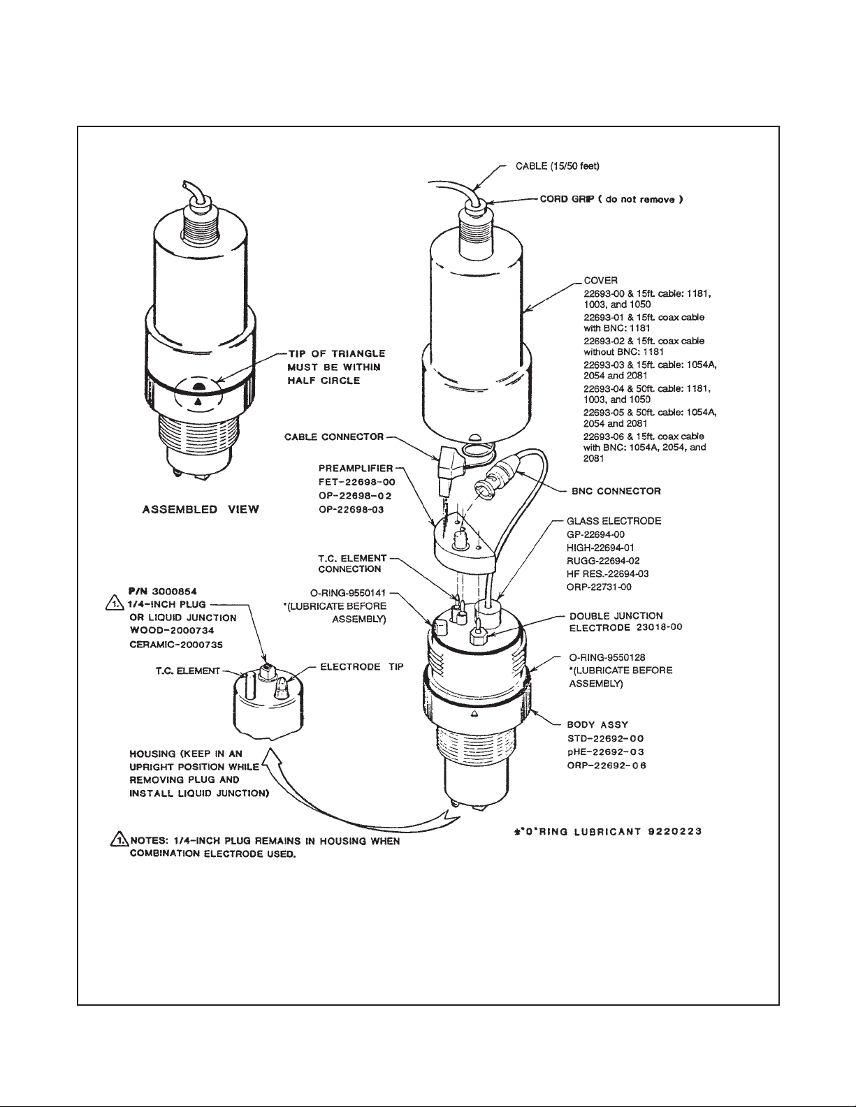
2.1 INSTALLATION. Prepare the sensor for instal lation
as follows (see Figure 2-1):
1. Remove the cover from the body by grasping the
body and rotating the cover 1/4 turn counterclockwise.
2. When the cover breaks loose from the body, pull
the cover straight out.
3. Lubricate the seals of the glass electrode with Oring lubricant, Rosemount Analytical P/N
2001928, and install the glass electrode in the
body. Tighten the electrode nut by hand. DO NOT
use tools.
CAUTION
Do not get lubricant on amber tip of glass
electrode. It will disrupt the electrical circuit
path.
4. Make sure the double junction electrode is thread-
ed tightly.
5. Plug the preamplifier (or remote connector) onto
the T.C. and reference electrode pins.
6. Connect the BNC connector from the glass elec-
trode to the preamplifier.
7. Install the body O-rings. Make sure they are clean,
and not twisted. Make sure the covers mating surfaces faces are clean.
NOTE
Both body O-rings must be installed and
lubricated to ensure a water tight seal.
Failure to seal the body properly will result
in water damage, in insertion applications.
8. Lubricate the body O-rings with O-ring lubricant,
P/N 2001928.
9. Plug the cable connector to the preamplifier, mak-
ing sure the cable is toward the center of the body.
10. Install the cover on the body so that the threads
will engage.
11. Rotate the cover until the triangle on the body
aligns with (or falls within) the adjacent mark on
the cover.
IMPORTANT!
12. While holding the sensor in an up side down position (see Figure 2-1), remove the 1/4 inch plug
from the electrode tip end of the sensor.
13. Install the liquid junction in place of the 1/4 inch
plug, using Teflon tape on the liquid junction
threads.
CAUTION
DO NOT use pipe joint compound or pipe
dope on the threads of the liquid junction.
The electrical circuit will be disrupted if the
liquid junction is contaminated.
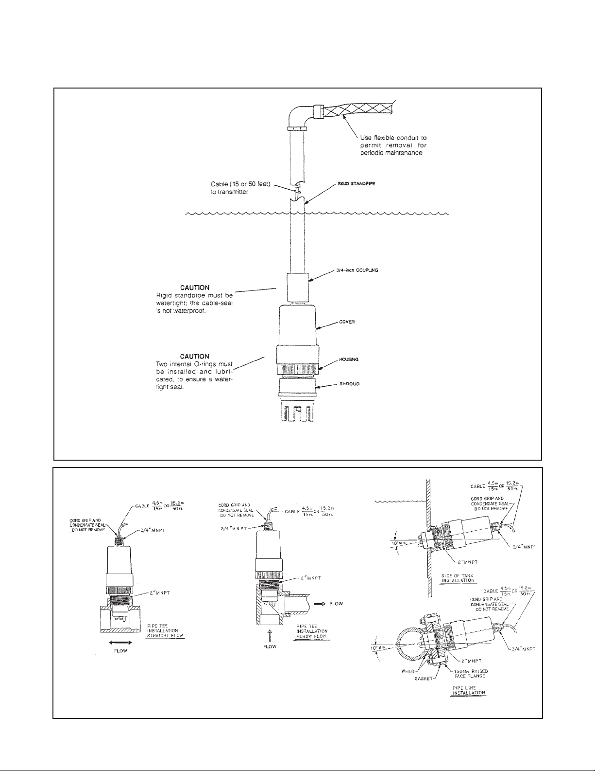
2.2 SUBMERSION INSTALLATION (Code 02). To
install the sensor in process proceed as follows (see
Figure 2-2):
1. Wrap Teflon tape on 3/4 inch MNPT threads of
cover and on standpipe threads. Seal must be
water tight. Cable gland is not waterproof. Do not
allow water to accumulate in the stand pipe.
CAUTION
Do not use a pipe wrench on the plastic
parts. Severe damage could result.
2. Attach a 3/14 inch coupling to the sensor.
3. Attach electrode shroud to 2 inch MNPT.
4. Feed cable through the rigid standpipe.
5. Attach the rigid standpipe to 1 inch coupling.
CAUTION
Rigid stand pipe must be water-tight; cable
seal is not waterproof.
6. Tighten all fittings and secure the standpipe to
minimize sensor movement. Use flexible conduit
at the top of the rigid standpipe to permit removal
of the sensor for periodic maintenance.
7. Refer to Section 2.6 and wire the sensor to the
transmitter as described.
Page 10
6
MODEL 381pH/ORP SECTION 2.0
INSTALLATION
FIGURE 2-1. Model 381 Sensor Component Locator Diagram
Page 11

7
MODEL 381pH/ORP SECTION 2.0
INSTALLATION
2.3 INSERTION INSTALLATION (Code 00). To install
the sensor in the side of a tank, in a pipeline, or in a
pipe “tee”, proceed as follows (see Figure 2-3):
CAUTION
Sensor must be installed within 80° of the
vertical plane (see Figure 2-3).
1. Use Teflon tape on pipe joint, and install sensor as
shown in Figure 2-3.
CAUTION
Do not use a pipe wrench on the plastic
sensor parts. Severe damage could result.
2. Tighten all fittings and sensor.
3. Refer to Section 2.6 for wiring instructions.
4. If desired, the cable may be installed in a con-duit.
Flexible conduit MUST be used at the sensor for a
short distance to permit removal for periodic maintenance. Use the 3/4 inch MNPT threads on the
cover to attach the conduit to the sensor.
2.4 FLOW THROUGH INSTALLATION (Code 03). To
install the sensor in the flow cell proceed as follows
(see Figure 2-4):
1. Attach the flow cell’s 3/4 inch MNPT to the sample
or process line. (Note flow direction on side of flow
cell.)
2. Holding the sensor with the electrode pointing up,
seat the upper O-ring (P/N 9550146) flush with the
sensor body above the 2-inch MNPT. Lubricate
with O-ring lubricant (P/N 2001928).
3. With the coupling nut thread in place, thread the
electrode shroud onto the sensor body (see Figure
2-4), insuring that the O-ring is properly seated
and does not become pinched or twisted.
NOTE
The coupling nut must be inserted between
the lower body assembly of the sensor and
electrode shroud (see Figure 2-4).
4. Next, place the lower O-ring (P/N 9550147) in the
flow cell and lubricate with O-ring lubricant (P/N
2001928).
5. Place sensor, coupling nut and electrode shroud in
the flow cell. Insure that the O-ring is seated properly.
6. Rotate sensor until the key on electrode shroud
drops into either the “open-flow” or “guarded” flow*
position.
7. Tighten the coupling nut and the flow cell fittings.
NOTE
Electrode shroud and coupling nut should
be hand tightened only. Do not use a
wrench. When tightening process or sample
line connectors to the flow cell do not use a
pipe wrench on the flow cell. Severe damage may result.
* In "guarded" flow position, solid particles in the flow
stream are diverted from electrode.
2.4.1 Installation Procedures For Low Flow
Conditions. It is extremely important that the measur-
ing electrode and liquid junction of any pH/ORP sensor
remain in contact with the process fluid at all times.
Under low flow conditions or where flow fluctuations
are common, sensor contact with the process fluid may
be interrupted unless piping procedures are followed to
prevent it.
A customer supplied valve should be installed to eliminate head pressure when the sensor is being removed
from the process. This valve may also serve as a grab
sample take-off point.
The installation drawing (Figure 2-5) shows the recommended piping procedures for the Model 381 pH/ORP
sensor in low flow conditions.
2.5 FLOW POWERED CLEANER INSTALLATION
(Code 04). To install the sensor in a flow cell with flow
powered cleaner, proceed as follows (see Figure 2-6):
1. Attach the flow cell’s 3/4 inch MNPT to sample or
process line. Note flow direction shown on the
side of the flow cell.
2. Insert the ring as shown in Figure 2-6. It should
snap in place.
3. Place the chamber into the flow cell. Notch must
be aligned for the chamber to go in place. Place
the Teflon balls (4 each) in the chamber.
4. Follow Steps 2 through 7 in Section 2.4 for sensor
installation into flow assembly (see Figure 2-4).
2.6 WIRING. Connect the wire lugs to the transmitter
terminals as shown in Figures 2-7 thru 2-10.
Page 12
8
MODEL 381pH/ORP SECTION 2.0
INSTALLATION
FIGURE 2-2. Submersion Installation Diagram
FIGURE 2-3. Insertion Installation Diagram
Page 13

9
MODEL 381pH/ORP SECTION 2.0
INSTALLATION
FIGURE 2-4. Flow Through Installation Diagram (Code 03 or 04)
FIGURE 2-5. Installation Details Low Flow Conditions Model 381 (Code 03 and 04)
Page 14

10
FIGURE 2-6. Retro-Fit Kit Code 04 Flow Powered Cleaner, Model 381
MODEL 381pH/ORP SECTION 2.0
INSTALLATION
PRESSURE DROP AND RECOMMENDED FLOW
RATES- FLOW POWERED CLEANER (CODE 04)
kPa
240
220
200
180
160
140
120
100
20
15
10
5
POSSIBLE ELECTRODE DAMAGE
ABOVE THE THIS POINT
PRESSURE DROP
RECOMMENDED OPERATING
RANGER
INEFFECTIVE CLEANING BELOW
THIS POINT
1234567 8
51015202530
gpm @ 60°
liters/min
PSIG
FLOW RATE
Page 15

11
FIGURE 2-7. Flow Through Diagram and Wiring (Code 03 or 04)
DWG. NO. REV.
40038105 L
MODEL 381pH/ORP SECTION 2.0
INSTALLATION
WHEN INCH AND METRIC DIMS
ARE GIVEN
MILLIMETER
INCH
Page 16

12
FIGURE 2-8. Remote Junction Box with Internal Preamp
DWG. NO. REV.
40038103 J
MODEL 381pH/ORP SECTION 2.0
INSTALLATION
WHEN INCH AND METRIC DIMS
ARE GIVEN
MILLIMETER
INCH
Page 17

13
FIGURE 2-9. Wiring with Weatherproof or Div. 2 (Code 52) Junction Box
DWG. NO. REV.
40038115 K
DWG. NO. REV.
40038116 I
MODEL 381pH/ORP SECTION 2.0
INSTALLATION
WHEN INCH AND METRIC DIMS
ARE GIVEN
MILLIMETER
INCH
Page 18

14
MODEL 381pH/ORP SECTION 2.0
INSTALLATION
2.9.2 Calibration
CAUTION
The solution used during the following check
is an acid and should be handled with care.
Follow the directions of the acid manufacturer. Wear the proper protective equipment. Do
not let the solution come in contact with skin
or clothing. If contact with skin is made,
immediately rinse with clean water.
1. Make a temporary electrical connection between the
sensor and the instrument.
2. Obtain a standard solution of saturated quinhydrone
(PN R508-160Z). This can also be made quite simply by adding a few crystals of quinhydrone to either
pH 4 or pH 7 buffer. Quinhydrone is only slightly soluble therefore a few crystals will be required. (Refer
to Section 4.3. for an alternate ORP standard solution).
3. Immerse the sensor in the standard solution. Allow
1-2 minutes for the ORP sensor to stabilize.
4. Adjust the standardize control of the instrument to
the solution value shown in Table 2-1. The resulting
potentials, measured with a clean platinum electrode
and saturated KCl/AgCl reference electrode, should
be within ±20 millivolts of the value shown in Table 2-
1. Solution temperature must be noted to insure
accurate interpretation of results. The ORP value of
saturated quinhydrone solution is not stable over
long periods of time. Therefore, these standards
should be made up fresh each time they are used.
TABLE 2-1.
ORP of Saturated Quinhydrone Solution
(In Millivolts)
5. Remove the sensor from the buffer, rinse and install
in the process.
2.7 START-UP AND CALIBRATION
2.8 MODEL 381 pH and pHE
2.8.1 SENSOR PREPARATION. Shake down the
sensor to remove any air bubbles that may be present
at the tip of the pH glass bulb. In most cases, the pH
sensor can simply be installed as shipped and readings with an accuracy of ± 0.6 pH may be obtained. To
obtain greater accuracy or to verify proper operation,
the sensor must be calibrated as a loop with its compatible analyzer or transmitter.
WARNING
Glass electrode must be wetted at all times
(in storage and in line) to maximize sensor
life.
2.8.2 CALIBRATION USING BUFFER SOLUTIONS
OR GRAB SAMPLES. The pH sensor-analyzer/ trans-
mitter loop may be calibrated by submersing the sensor
in a buffer solution (standard solutions of known pH values) or in a process grab sample whose pH value
maybe checked by a calibrated laboratory or portable
pH meter. Please refer to the analyzer's or the trans-
mitter’s respective instruction manuals for proper
calibration procedures.
2.9 MODEL 381 ORP.
2.9.1 MODEL 396P ORP. Most industrial applications
have a number of ORP reactions occurring in
sequence or simultaneously. There can be several
components that are oxidized or reduced by the
reagents that are used. Theoretically, the ORP potential is absolute because it is the result of the oxidationreduction equilibrium. However, the actual measured
potential is dependent on many factors, including the
condition of the surface of the ORP platinum electrode. Therefore, the sensor should be allowed 1-2
hours to become “conditioned” to the stream
when first set-up or after being cleaned.
pH 4 Solution pH 7 Solution
Temp °C 20 25 30 20 25 30
Millivolt Potential 268 264 260 94 87 80
Page 19

15
MODEL 381pH/ORP SECTION 3.0
MAINTENANCE
SECTION 3.0
MAINTENANCE
3.1 GENERAL. This section provides instructions for
performing periodic maintenance and for determining
the cause of a malfunction (troubleshooting).
3.2 PERIODIC MAINTENANCE. The following periodic maintenance is based on operation in a water sample. Determine the schedule for the operation being
maintained from past experience, or by analyzing data
gathered since initial installation of the sensor.
3.2.1 Monthly. Perform the following maintenance
monthly:
1. Remove the sensor from the solution or sample
and observe the condition of the electrode tip.
2. If the electrode tip is coated, clean it with a soft,
clean cloth or tissue moistened with a mild, nonabrasive detergent, and rinse the electrode tip with
clean water. Detergents may be used to remove
oil and grease coatings.
3. If Step 2 does not clean the electrode tip, remove
the electrode and clean it with a dilute, 0.1
hydrochloric acid solution and rinse with clean
water. HCI may be used to remove thin film and
scale coatings not removed with a damp cloth or
detergents.
4. Check calibration and install the sensor in the
process as instructed in Section 2.0.
3.2.2 Annually. Perform the following maintenance
annually (not required for combination electrode):
1. Remove the sensor from the process.
2. While holding the sensor in an upright position,
remove and discard the liquid junction.
3. Drain the solution from the sensor body and rinse
the inside of the body with clean, warm water.
4. Remove the cover from the body by grasping the
body and rotating the cover ¼-turn in the counterclockwise direction.
5. When the cover breaks loose from the body, pull
straight out on the cover and disconnect the cable
connector from the preamplifier.
6. Disconnect the electrode BNC connector from the
preamplifier and then unplug the preamplifier from
the body.
7. Remove and discard the double junction electrode.
8. Remove and discard the O-rings on the body.
9. Install a new double junction electrode in the body
(refer to Table 3-4 Spare Parts).
10. Make sure the upper and lower body O-ring sealing surfaces are clean, and lubricate the new Orings with O-ring lubricant (P/N 2001928). Install
the O-rings making sure they are not twisted.
11. Install the preamplifier on the body and make sure
all connections are secure and that both O-rings
are in place.
12. Install the cover on the body so the threads will
engage.
13. Rotate the cover until the triangle on the body
aligns with (or falls within) the adjacent mark on
the cover.
CAUTION
DO NOT use a pipe wrench on the body or
cover. Severe damage could result.
14. While holding the sensor in an upright position, fill
the reference chamber in the body (through the
liquid junction opening) with gel solution (P/N
9210342). Care must be taken to remove as much
air as possible from the reference cell.
15. Wrap Teflon tape on a new liquid junction (see
Table 3-4 Spare Parts) and install the liquid junction in the body.
16. Test the sensor per Section 2.7. Install the sensor
as described in Section 2.0.
NOTE
Flow-through sensor (Codes 03 & 04). Upper
and lower flow cell O-rings should be
replaced at this time. Lubricate new Orings with O-ring lubricant (P/N 2001928)
and reinstall sensor as described in
Section 2.4. & 2.5.
Page 20

16
MODEL 381pH/ORP SECTION 3.0
MAINTENANCE
3.3 MODEL 381
3.3.1 Platinum Electrode Check. The platinum elec-
trode may be checked as follows: There are two types
of standard solutions which may be used to check the
ORP electrode/transmitter system.
Type 1: One type of commonly used ORP standard
solution is the saturated quinhydrone solution. A commonly used ORP standard solution is a saturated quinhydrone solution. This can be made by simply adding
a few quinhydrone crystals to either a 4 pH or a 7 pH
buffer. Quinhydrone is only sightly soluble so only a
few crystals will be required. The solution will have a
yellow color. The resulting potentials should be within
±20 millivolts of the value shown in Table 3-1. The ORP
value of saturated quinhydrone solution is not stable
for long periods of time and therefore new solutions
should be made each time.
CAUTION
The solution used during the following check is
an acid and should be handled with care.
Follow the directions of the acid manufacturer.
Wear the proper protective equipment. If contact with skin of clothing is made, immediately
rinse with plenty of clean water.
Type 2: A second ORP standard solution is the FerricFerrous Ammonium Sulfate Solution (PN R508-16OZ),
and it can be ordered as a spare part; otherwise, it can
be prepared from the following recipe: Dissolve 39.2
grams of reagent grade ferrous ammonium sulfate,
Fe(NH4)2(SO4)2• 6H2O and 48.2 grams of reagent
grade ferric ammonium sulfate, FeNH4(SO4)2•
12H2O, in approximately 700 milliliters of water (distilled water is preferred, but tap water is acceptable).
Slowly and carefully add 56.2 milliliters of concentrated
sulfuric acid. Add sufficient water to bring the total solution volume up to 1000 ml. This standard ORP solution,
although not as simple to prepare as the quinhydrone
recipe, is much more stable, and will maintain its millivolt value for approximately one year when stored in
glass containers. This solution (ferric/ferrous ammonium sulfate) will produce a nominal ORP of 476 +20 mV
at 25°C when used with a saturated KCl/AgCl reference electrode and platinum measuring electrode.
Some tolerance in mV values is to be expected due to
the rather large liquid reference junction potentials
which can arise when measuring this strongly acidic
and concentrated solution. However, if the measuring
electrodes are kept clean and in good operating condition, consistently repeatable calibrations can be carried
out using this standard solution.
3.3.2 Cleaning Platinum Electrode. The electrode is
never exposed to these undesirable compounds. In the
event poisoning is suspected, the electrode can be
restored to normal operation by simply cleaning the platinum electrode with baking soda. Polish it by rubbing it
with a damp paper towel and baking soda until a bright,
shiny appearance is attained.
TABLE 3-1. ORP of Saturated Quinhydrone Solutions
pH 4 pH 7
Temperature °C 20 25 30 20 25 30
Millivolt Potential 268 264 260 94 87 80
Page 21

17
Trouble Probable Cause Remedy
Meter reads off scale. Reference electrolyte depleted. Replace reference electrolyte as
instructed in Section 3.2.2.
Defective preamplifier. Check preamplifier as instructed in
Section 3.4 and replace
preamplifier if defective.
T.C. element shorted. Check T.C. element as instructed in
Section 3.5, and replace body if
defective.
Electrode not in solution or sample Make sure sensor is in solution or that
stream is not full. sample stream is full (refer to Section
2.0 for installation details).
Open glass electrode. Replace glass electrode.
Plugged liquid junction. Replace liquid junction.
Recharge reference cell.
Reference element open- Replace reference element.
no contact.
Meter reads between 3 and 6 pH Electrode cracked. Replace electrode.
regardless of actual pH of
solution or sample.
Meter indication swings widely T.C. element shorted. Check T.C. element as instructed in
in AUTO T.C. Mode. Section 3.5 and replace body if
defective.
Span between buffers extremely T.C. element open. Check T.C. element as instructed in
short in AUTO T.C. mode. Section 3.5 and replace body if
defective.
Sluggish or slow meter indication Electrode coated. Clean electrode as instructed in
for real changes in pH level. Section 3.2.1.
Electrode defective. Replace electrode.
Transmitter cannot be Electrode coated or cracked. Clean electrode as instructed in
standardized. Section 3.2.1 and, if cracked,
replace electrode.
Reference chamber is contaminated Replace gel solution as
instructed in Section 3.2.2.
Defective preamplifier. Check preamplifier as instructed in
Section 3.4 and replace if
defective.
If trouble still persists, micro-junction Replace micro-junction electrode.
electrode is defective.
Meter short spans. Old glass electrode (greater than 1 Replace electrode.
year use).
Coated glass. Clean with soft cloth and clean water.
TABLE 3-1. Troubleshooting
MODEL 381pH/ORP SECTION 3.0
MAINTENANCE
Page 22

18
3.4 PREAMPLIFIER TROUBLESHOOTING. To deter-
mine if the preamplifier is operable, proceed as follows:
1. Remove the sensor from process.
2. Remove the cover from the body by grasping the
body and rotating the cover 1/4 turn in the counter-clockwise direction.
3. When the cover breaks loose from the body, pull
straight out on the cover to expose the components attached to the body and disconnect the
BNC connector from the preamplifier, leaving the
cable connected. Inspect the internal pre amplifier
area for signs of moisture or corrosion; moisture
can short out the preamplifier. Dry all parts thoroughly before testing.
4. Short the center pin of the BNC on the preamp-lifier to the outside of the BNC connector.
5. The meter indication should be approximately
center scale (7 pH).
6. If the meter indication is not as specified in Step 5,
proceed to the transmitter instruction manual for
further troubleshooting. If the transmitter is operable with the preamplifier bypassed, then the preamplifier is defective.
7. Unplug the preamplifier from the body.
8. Plug a new preamplifier into the body.
9. Plug the BNC connector of the glass electrode into
the preamplifier.
10. Make sure all O-rings are clean, lubricated and in place.
11. Plug the cable connector into the preamplifier, making
sure the cable is towards the center of the body.
12. Install the cover on the body so that the threads
engage.
13. Rotate the cover until the triangle on the body
aligns with (or falls within) the adjacent mark on
the cover.
CAUTION
DO NOT use a pipe wrench on the body or
cover. Severe damage could result.
14. Install the sensor as described in Section 2.0.
MODEL 381pH/ORP SECTION 3.0
MAINTENANCE
3.5 T Automatic Temperature Compensator. The temper-
ature compensator element is temp erature sensitive and
can be checked with an ohmmeter. Resistance increases
with temperature.
The 3K element will read 3000 ohms ± 1% at 25°C (77°F)
and a Pt-100 will read 110 ohms. Resistance varies with temperature for a 3K and Pt-100 element and can be determined
according to Table 3-2 or the following formula:
RT=Ro[l+R1(T-20)]
Where R
T
= Resistance
T = Temperature in °C
Refer to Table 3-3 for R
o
and R
1
values
TABLE 3-3
Roand R1VALUES FOR TEMPERATURE
COMPENSATION ELEMENTS
TABLE 3-2
TEMPERATURE vs RESISTANCE OF AUTO
T.C. ELEMENT
Temperature °C Resistance
(Ohms) ± 1%
3K PT-100
0 2670 100.0
10 2802 103.8
20 2934 107.7
25 3000 109.6
30 3066 111.5
40 3198 115.4
50 3330 119.2
60 3462 123.1
70 3594 126.9
80 3726 130.8
90 3858 134.6
100 3990 138.5
Temperature
Compensation Element
R
o
R
1
3K 2934 .0045
PT-100 107.7 .00385
Page 23

19
RECOMMENDED
PART NUMBER DESCRIPTION CODE QUANTITY
2000734 Liquid junction wood/Kynar 20 2
2000735 Liquid junction ceramic/Kynar 21 2
2001928 O-ring lubricant ALL 2
22692-00 Body, Uniloc standard T.C. 30
22692-03 Body, Pt100 T.C. 31
22692-06 Body w/o T.C. 32
22693-00 Cover, for integral preamp, w/15 ft. cable 40
22693-01 Cover, for remote preamp, w/15 ft. coax 41
22693-02 Cover for remote preamp, w/15 ft. coax, no BNC 42
22693-03 Cover, for integral preamp, w/15 ft. cable, Model 1054/2054 Series pHE-40
22693-04 Cover, for integral preamp w/50 ft. cable 43
22693-05 Cover, for integral preamp, w/50 ft. cable, Model 1054/2054 Series pHE-43
22693-06
Cover, for remote preamp, w/15 ft. coax, w/BNC Model 1054/2054 Series
pHE-41
22694-00 General purpose pH electrode 10 2
22694-01 High pH electrode 11 2
22694-02 Ruggedized pH electrode 12 2
22694-03 HF resistive pH electrode 15 2
22698-00 Preamplifier, Models 1003 pH and 1023 ORP 51 1
22698-02 Preamplifier, Models 1181 pH/ORP, 1050 pH/1060 ORP 50 1
22698-03 Preamplifier, Models 1054/2054 Series 54 1
22723-00 Kit, cleaning balls 04 1
22731-00 Platinum ORP electrode 13 2
22751-00 (Qty. 5) O-ring, Viton 2-037, upper body kit (9550141) ALL 1 set
22751-01 (Qty. 5) O-ring, Viton 2-040, lower body kit (9550128) ALL 1 set
22811-01 Retro-fit kit, flow powered cleaner 00, 02
22892-00 Retro-fit kit, flow powered cleaner 03
23018-00 Micro junction, reference element ALL 2
32602-00 Flow cell 03,04
32605-00 Electrode shroud 02, 03
32606-00 Coupling nut 03,04
32792-00 Shroud, modified 04
32793-00 Ring, chamber 04
32794-00 Chamber 04
7900058 Gold ORP electrode 14 2
9210342 KCl Gel reference solution, 10 oz./250 ml ALL 2
9550146 (Qty. 1) O-ring, shroud assembly 02, 03, 04 2
9550147 (Qty. 1) O-ring, flow cell assembly 03, 04 2
TABLE 3-4. Model 381 Spare Parts
MODEL 381pH/ORP SECTION 3.0
MAINTENANCE
PART NUMBER DESCRIPTION
1000856 Handrail mounting bracket for submersion service. For use with Models 1003 & 1023.
1000857 Handrail mounting bracket for submersion service. For use with remote NEMA 4X junction box.
23296-00
Remote Division 2 junction box for internal preamp for use with Models 1181pH/ORP, 1050/1060, 1003/1023
23296-01 Remote Division 2 junction box for internal preamp for use with Models
1054/1054A/2054pH ORP/2081pH.
22996-00 Remote weatherproof junction box for internal preamp.
22719-02 Remote weatherproof junction box without preamp, for cable extension.
22727-00 Ultrasonic cleaner with generator, 115 VAC/230 VAC 50/60 Hz, switch selectable. Includes mounting
hardware and 20 feet of interconnecting cable. (For submersion service).
9200160 Extension cable, sensor or remote preamp to analyzer, 4 conductor, 22 AWG, shielded (Specify length).
22811-00 Flow cell with electrode shroud.
22892-00 Flow powered cleaner retrofit kit (for use with Code 03 sensors).
TABLE 3-5. Accessories
Page 24

20
Page 25

21
MODEL 381pH/ORP SECTION 4.0
ULTRASONIC CLEANER
SECTION 4.0
ULTRASONIC CLEANER
4.1 ULTRASONIC CLEANER (P/N 22727-00). This
accessory provides an ultrasonic cleaner and mounting hardware for either continuous or inter-mittent
cleaning of the measuring electrode and liquid junction
on the Model 381. The information in the following
paragraph is supplemental to the information in
Sections 1.0 thru 3.0.
4.2 SPECIFICATIONS. The ultrasonic cleaner operates on either 115 Vac or 230 Vac, 50/60 Hz. The mode
is jumper selectable within the generator enclosure.
The generator is shipped in the 115 Vac configuration.
4.3 INSTALLATION. The ultrasonic generator is
shipped with special cushioning material. Before opening the container or removing any packing material, all
items should be inspected for any possible shipping
damage. If any damage is found, the carrier should be
notified. Check the generator enclosure for damage to
the finish; loosen the door clamps and inspect the circuit board and components. If there is apparent damage, contact the carrier for instructions. The packing
container and cushioning material should be retained
should it ever become necessary to return the generator to the factory. Install the ultrasonic cleaner as follows:
1. Mechanical Installation. Although the generator is
designed to be located in a process environ-ment,
corrosive atmospheres and excessive vibration
should be avoided if possible. The ultrasonic
transducer is shipped loose along with mounting
hardware and mounting instructions. Check to
make certain all connections are secure. Refer to
Figure 4-1 and 4-2 for mounting dimensions and
select a convenient location for the generator.
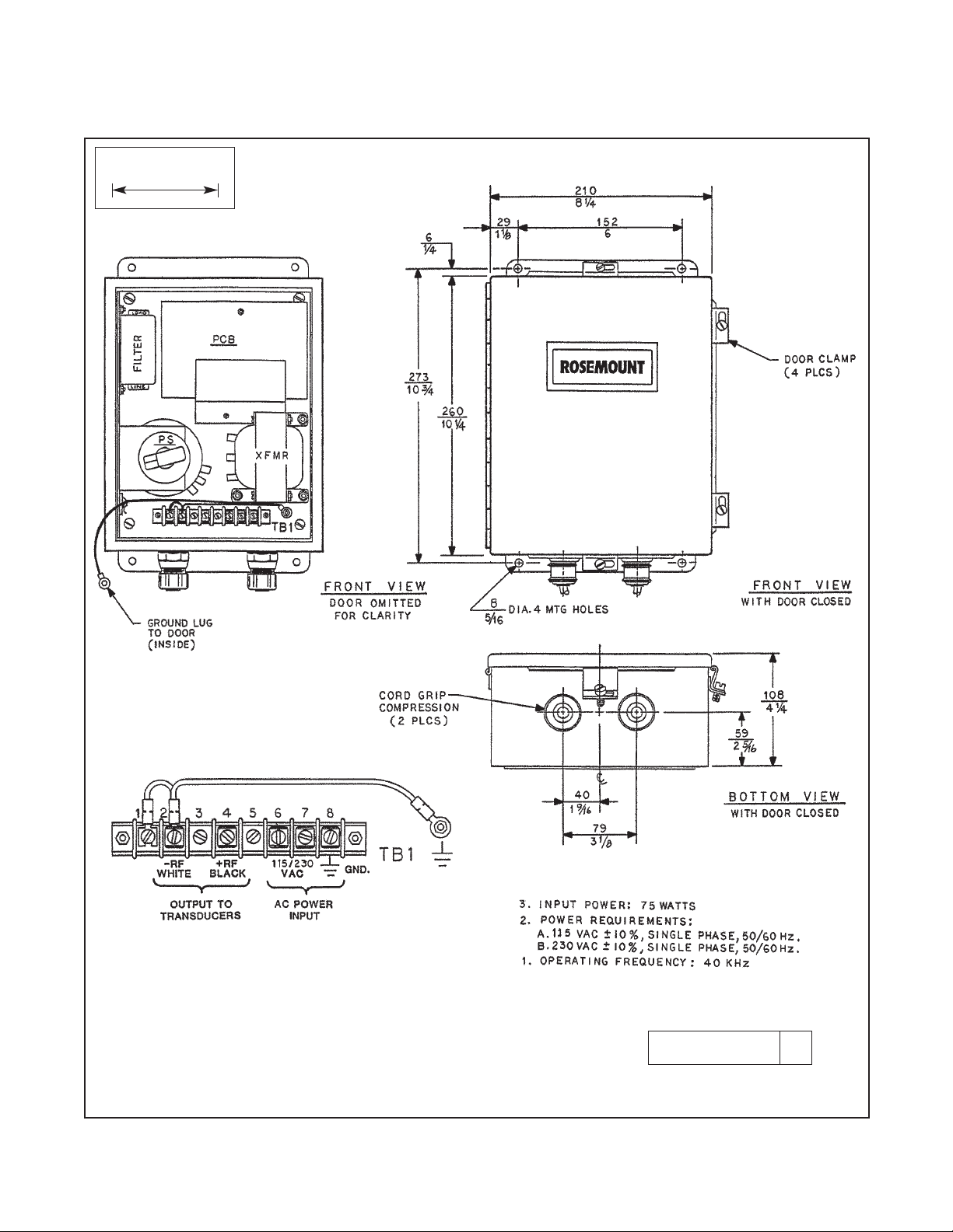
2. Electrical Installation. An external line switch
should be installed to disconnect power from the
generator for maintenance or periods of non-use.
Apply input power (refer to Figure 4-2) as follows:
Ground to TB1-8, hot to TB1-6, and neutral to TB1-7.
CAUTION
Make sure the 115/230 jumpers on the
transformer are in the proper position for
the supply voltage being used. The generator will be seriously damaged if 230 Vac is
supplied with the jumpers in the 115 Vac
position.
The power output is approximately 1400 volts at 0.002
amp, at a frequency of 40 to 45 kHz. The transducer is
supplied with 20 feet of interconnecting cable in a
polypropylene protective sheath. Output connections
are made at TB1-4 for R.F. (+) and TB1-2 for RF(-).
Make sure the AC power line ground is properly connected to the generator’s input terminals.
CAUTION
Do not run any ultrasonic cleaner power,
wiring input or output, in the same conduit
as the signal wiring from the sensor.
4.4 OPERATION. Submerge the sensor into sample
and start the sensor as instructed in Section 2.0. After
measuring system is in operation, apply AC power to
the ultrasonic cleaner. Over a period of time (usually
several days), gradually increase the gain until the
power setting is sufficient to keep the electrodes free of
process buildup.
CAUTION
Increase gain slowly and apply only the
necessary amount of power. Excessive
power may damage the electrode. Once
initial start-up is complete, further adjustment or calibration is not normally required
unless there are drastic changes in the
composition of the process sample.
Page 26

22
4.4 Operation (continued)
NOTE
When the ultrasonic cleaner is used on
some slurry applications (such as car- bonates and phosphates), continuous ultrasonic cleaning is not recommended as this
may tend to compact the solids of the slurry on the electrode into a hard, cement like
coating. Instead, it is recommended that a
shock-type treatment be applied (i.e., for
every three hours of operation, employ 30
minutes of ultrasonic cleaning). The interval and duration of the cleaning, as well as
the power setting utilized, are determined
by the individual application. Factors such
as the concentration of carbonates or
phosphates, flow velocities, temperature,
etc., must all be considered.
1. Output Power Adjustment. The output power
adjustment on the ultrasonic generator is located
on the powerstat. The powerstat is adjusted with
the knob marked as PS: (Refer to Figure 4-2), and
determines the cleaning efficiency of the unit by
adjusting the power input of the generator. Proper
adjustment is made by turning the powerstat knob
counter-clockwise (minimum power position) and
gradually increasing the power, by turning the
knob clockwise, until the power is sufficient to
keep the electrode clean. This is usually accomplished over a period of several days.
4.5 MAINTENANCE. The ultrasonic cleaner should
operate continuously (with the exception of carbonate
and phosphate slurries) and requires no maintenance,
calibration, or adjustment, except that the power
adjustment should be as low as possible consistent
with good cleaning action. The ultrasonic transducer is
completely sealed and should not be operating while
troubleshooting the sensor or transmitter.
1. Troubleshooting. In case problems arise in the
functioning of either the generator or the transducer, the entire assembly should be returned to
the factory for servicing. No electronic repair work
of any kind should be attempted in the field, or the
warranty will be voided. Whether the unit is still
under warranty or not, field troubleshooting is not
recommended, and Rosemount Analytical cannot
be liable for operation or safety of equipment that
has been repaired or modified by persons other
than its factory or their trained and authorized
Field Engineers. If your unit’s warranty has
expired, and field troubleshooting is still desired,
waveforms, frequency and voltages can be
obtained directly from Branson Ultrasonic, Eagle
Road, Danbury, CT 06810, (203) 796-0400. The
circuit is fundamentally identical for both the old
and new version.
4.6 REPLACEMENT PARTS. The ultrasonic generator
may be ordered as a unit (P/N 22990-00). The ultrasonic transducer is a sealed unit and cannot be conveniently repaired in the field. While it is not likely that the
transducer will fail electrically or mechanically, certain
process streams may contain corrosive compounds
which, in time could attack and ultimately destroy the
316 Stainless Steel faceplate. The number of spare
transducers (P/N 2001463) needed on hand as
replacement stock, should be determined on an individual basis, with regard to specific application conditions.
MODEL 381pH/ORP SECTION 4.0
ULTRASONIC CLEANER
Page 27

23
FIGURE 4-1. Model 381 Ultrasonic Cleaner and Wiring
DWG. NO. REV.
40038156 F
MODEL 381pH/ORP SECTION 4.0
ULTRASONIC CLEANER
WHEN INCH AND METRIC DIMS
ARE GIVEN
MILLIMETER
INCH
Page 28
24
FIGURE 4-2. Dimensional and Component Locator Ultrasonic Generator
MODEL 381pH/ORP SECTION 4.0
ULTRASONIC CLEANER
WHEN INCH AND METRIC DIMS
ARE GIVEN
MILLIMETER
INCH
DWG. NO. REV.
40037505 D
Page 29

25
MODEL 381 SECTION 5.0
RETURN OF MATERIAL
SECTION 5.0
RETURN OF MATERIAL
5.1 GENERAL. To expedite the repair and return of
instruments, proper communication between the customer and the factory is important. The “Return of
Materials Request” form is provided for you to copy and
use in case the situation arises. The accuracy and
completeness of this form will affect the processing
time of your materials. Call 1 (949) 757-8500 for a
Return Materials Authorization (RMA) number.
5.2 WARRANTY REPAIR. The following is the procedure for returning instruments still under warranty.
1. Contact the factory for authorization.
2. Complete a copy of the “Return of Materials
Request” form as completely and accurately as
possible.
3. To verify warranty, supply the factory sales order
number or the original purchase order number. In
the case of individual parts or sub-assemblies, the
serial number on the unit must be supplied.
4. Carefully package the materials and enclose your
“Letter of Transmittal” and the completed copy of
the “Return of Materials Request” form. If possible, pack the materials in the same manner as it
was received.
IMPORTANT
Please see second section of “Return of
Materials Request Form”. Compliance to
the OSHA requirements is mandatory for
the safety of all personnel. MSDS forms
and a certification that the instruments
have been disinfected or detoxified are
required.
5. Send the package prepaid to:
Rosemount Analytical Inc.
2400 Barranca Parkway
Irvine, CA 92606
Attn: Factory Repair
RMA No. ____________
Mark the package: Returned for Repair
Model No. ____
5.3 NON WARRANTY REPAIR.
1. Contact the factory for authorization.
2. Fill out a copy of the “Return of Materials Request”
form as completely and accurately as possible.
3. Include a purchase order number and make sure
to include the name and telephone number of the
right individual to be contacted should additional
information be needed.
4. Do Steps 4 and 5 of Section 5.2.
NOTE
Consult the factory for additional information regarding service or repair.
Page 30

FROM: RETURN BILL TO:
_____________________________ _____________________________ _____________________________
_____________________________ _____________________________ _____________________________
_____________________________ _____________________________ _____________________________
CUSTOMER/USER MUST SUBMIT MATERIAL SAFETY SHEET (MSDS) OR COMPLETE STREAM COMPOSITION, AND/OR
LETTER CERTIFYING THE MATERIALS HAVE BEEN DISINFECTED AND/OR DETOXIFIED WHEN RETURNING ANY PRODUCT, SAMPLE OR MATERIAL THAT HAVE BEEN EXPOSED TO OR USED IN AN ENVIRONMENT OR PROCESS THAT CONTAINS A HAZARDOUS MATERIAL ANY OF THE ABOVE THAT IS SUBMITTED TO ROSEMOUNT ANALYTICAL WITHOUT
THE MSDS WILL BE RETURNED TO SENDER C.O.D. FOR THE SAFETY AND HEALTH OF OUR EMPLOYEES. WE THANK
YOU IN ADVANCE FOR COMPLIANCE TO THIS SUBJECT.
SENSOR OR CIRCUIT BOARD ONLY:
(Please reference where from in MODEL / SER. NO. Column)
1. PART NO.__________________________1. MODEL_________________________________1. SER. NO. ________________
2. PART NO.__________________________2. MODEL_________________________________2. SER. NO. ________________
3. PART NO.__________________________3. MODEL_________________________________3. SER. NO. ________________
4. PART NO.__________________________4. MODEL_________________________________4. SER. NO. ________________
PLEASE CHECK ONE:
REPAIR AND CALIBRATE DEMO EQUIPMENT NO. __________________________
EVALUATION OTHER (EXPLAIN) _______________________________
REPLACEMENT REQUIRED? YES NO _________________________________________________
DESCRIPTION OF MALFUNCTION:
______________________________________________________________________________________________________
______________________________________________________________________________________________________
______________________________________________________________________________________________________
WARRANTY REPAIR REQUESTED:
YES-REFERENCE ORIGINAL ROSEMOUNT ANALYTICAL ORDER NO. ________________________________________
CUSTOMER PURCHASE ORDER NO. _________________________________________________
NO-PROCEED WITH REPAIRS-INVOICE AGAINST P.O. NO. _________________________________________________
NO-CONTACT WITH ESTIMATE OF REPAIR CHARGES: LETTER __________________________________________
PHONE
___________________________________________
NAME _____________________________________________________ PHONE ________________________________________
ADDRESS ___________________________________________________________________________________________________
______________________________________________________________ ZIP ________________________________________
RETURN AUTHORITY FOR CREDIT ADJUSTMENT [Please check appropriate box(s)]
WRONG PART RECEIVED REPLACEMENT RECEIVED
DUPLICATE SHIPMENT REFERENCE ROSEMOUNT ANALYTICAL SALES ORDER NO.__________
RETURN FOR CREDIT RETURN AUTHORIZED BY: ______________________________________
WARRANTY DEFECT____________________________________________________________________________________
_____________________________________________________________________________________________________
24-6047
RETURN OF MATERIALS REQUEST
•IMPORTANT!
This form must be completed to ensure expedient factory service.
R
E
P
A
I
R
S
T
A
T
U
S
R
E
A
S
O
N
F
O
R
R
E
T
U
R
N
C
U
S
T
O
M
E
R
N
O
T
I
C
E
T
O
S
E
N
D
E
R
Emerson Process Management
Rosemount Analytical Inc.
2400 Barranca Parkway
Irvine, CA 92606 USA
Tel: (949) 757-8500
Fax: (949) 474-7250
http://www.RAuniloc.com
© Rosemount Analytical Inc. 2001
Page 31

WARRANTY
Goods and part(s) (excluding consumables) manufactured by Seller are warranted to be free from defects in workmanship and material under normal use and service for a period of twelve (12) months from the date of shipment by Seller.
Consumables, pH electrodes, membranes, liquid junctions, electrolyte, O-rings, etc. are warranted to be free from defects
in workmanship and material under normal use and service for a period of ninety (90) days from date of shipment by Seller.
Goods, part(s) and consumables proven by Seller to be defective in workmanship and / or material shall be replaced or
repaired, free of charge, F.O.B. Seller's factory provided that the goods, parts(s), or consumables are returned to Seller's
designated factory, transportation charges prepaid, within the twelve (12) month period of warranty in the case of goods
and part(s), and in the case of consumables, within the ninety (90) day period of warranty. This warranty shall be in effect
for replacement or repaired goods, part(s) and consumables for the remaining portion of the period of the twelve (12)
month warranty in the case of goods and part(s) and the remaining portion of the ninety (90) day warranty in the case of
consumables. A defect in goods, part(s) and consumables of the commercial unit shall not operate to condemn such commercial unit when such goods, parts(s) or consumables are capable of being renewed, repaired or replaced.
The Seller shall not be liable to the Buyer, or to any other person, for the loss or damage, directly or indirectly, arising
from the use of the equipment or goods, from breach of any warranty or from any other cause. All other warranties,
expressed or implied are hereby excluded.
IN CONSIDERATION OF THE STATED PURCHASE PRICE OF THE GOODS, SELLER GRANTS ONLY THE ABOVE
STATED EXPRESS WARRANTY. NO OTHER WARRANTIES ARE GRANTED INCLUDING, BUT NOT LIMITED TO,
EXPRESS AND IMPLIED WARRANTIES OF MERCHANTABILITY AND FITNESS FOR A PARTICULAR PURPOSE.
RETURN OF MATERIAL
Material returned for repair, whether in or out of warranty, should be shipped prepaid to:
Rosemount Analytical Inc.
Uniloc Division
2400 Barranca Parkway
Irvine, CA 92606
The shipping container should be marked:
Return for Repair
Model
_______________________________
The returned material should be accompanied by a letter of transmittal which should include the following information
(make a copy of the "Return of Materials Request" found on the last page of the Manual and provide the following thereon):
1. Location type of service, and length of time of service of the device.
2. Description of the faulty operation of the device and the circumstances of the failure.
3. Name and telephone number of the person to contact if there are questions about the returned material.
4. Statement as to whether warranty or non-warranty service is requested.
5. Complete shipping instructions for return of the material.
Adherence to these procedures will expedite handling of the returned material and will prevent unnecessary additional
charges for inspection and testing to determine the problem with the device.
If the material is returned for out-of-warranty repairs, a purchase order for repairs should be enclosed.
Page 32

Credit Cards for U.S. Purchases Only.
The right people,
the right answers,
right now.
ON-LINE ORDERING NOW AVAILABLE ON OUR WEB SITE
http://www.raihome.com
Specifications subject to change without notice.
Emerson Process Management
Liquid Division
2400 Barranca Parkway
Irvine, CA 92606 USA
Tel: (949) 757-8500
Fax: (949) 474-7250
http://www.raihome.com
© Rosemount Analytical Inc. 2007
 Loading...