

Page 1
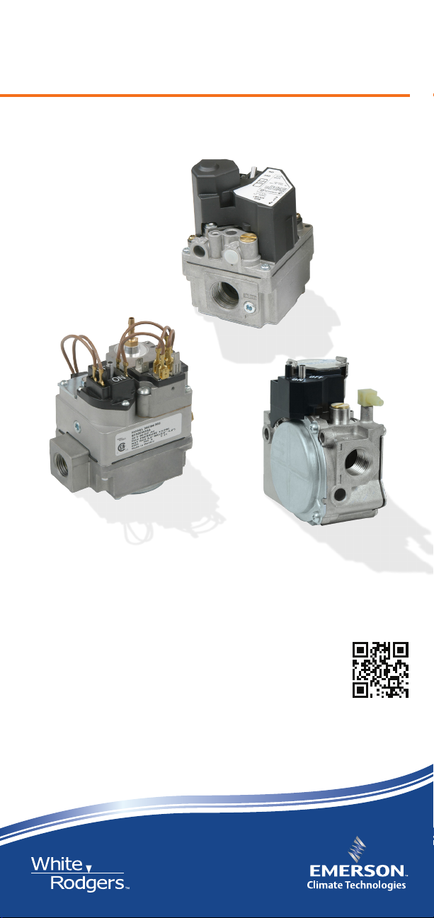
Gas Valve Cross Reference
for Furnaces, Boilers and Heaters
36H
36C
36J
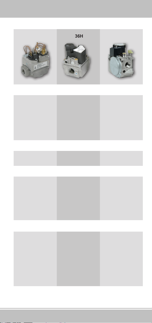
White-Rodgers36 Series
Complete online Cross Reference for
White-Rodgers and competitive gas valves
White-Rodgers is the leading manufacturer of gas valves to the OEM. When it’s
time to replace – replace with the same brand trusted by OEMs on their equipment!
www.white-rodgers.com
R-4360
Gas Valve Cross Reference 1
Page 2
Index
Gas Valve Selection Guide ................................................. 3
Range of Operation ............................................................ 5
Nomenclature ..................................................................... 6
36C .............................................................................. 6
36H .............................................................................. 7
36J............................................................................... 7
System Applications ........................................................... 8
Product Features and Specications .................................. 11
36C .............................................................................. 11
36H .............................................................................. 12
36J............................................................................... 13
Product Accessories ........................................................... 14
Gas Valves Cross Reference ............................................. 15
Online Cross Reference
For complete online
Cross Reference
Emerson Climate Technologies Mobile Toolbox
WRMobile™ provides instant access to product
replacement information including wiring diagrams,
sell sheets, installation and operating instructions
for thermostats, gas valves and HVAC controls.
Scan and download the App here.
White-Rodgers Technical Support
800-284-2925
White-Rodgers Customer Service
888-725-9797
The White-Rodgers replacement information is provided without charge as a complimentary
service and is therefore given on the express understanding and agreement of the
recipient that it is given without warranty (express or implied) or liability of any kind. It is
the responsibility of the installer to verify that a White-Rodgers replacement is suitable for
installation. This may require referring to product installation instructions, contacting the
original equipment manufacturer, contacting a qualied service person or other steps. Final
responsibility for the selection and application of a control rests solely with the installer.
R-4360 1236
2 Gas Valve Cross Reference
Page 3
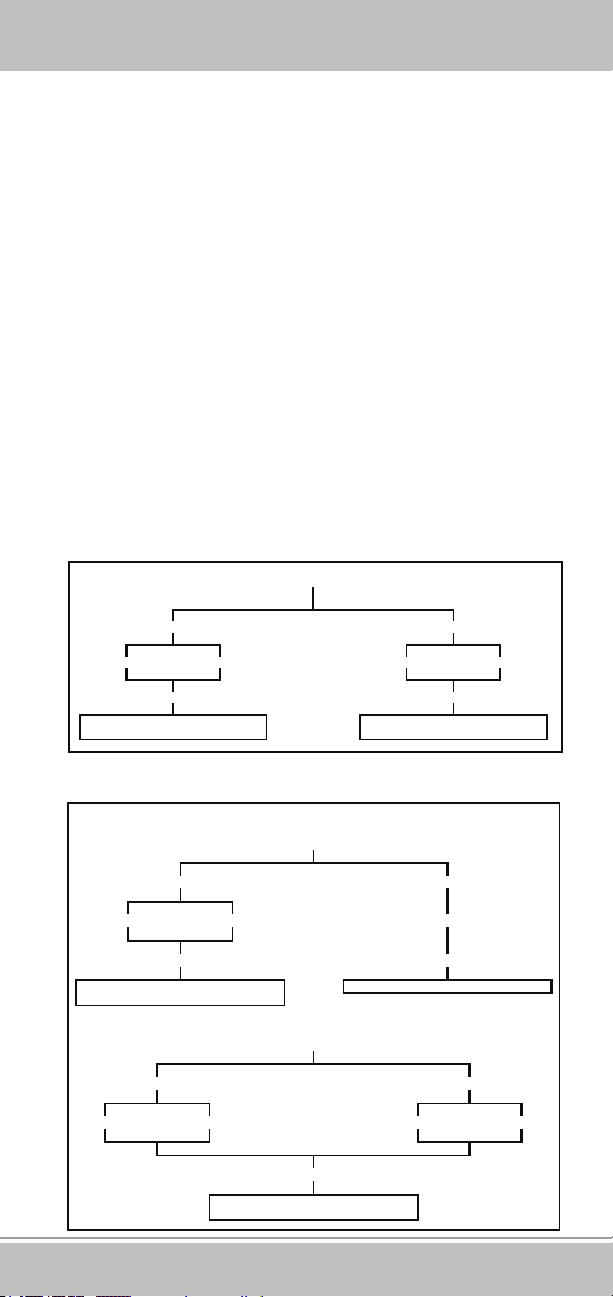
►Gas Valve Selection Guide
gS
Hot Surface Ignition
Direct Spark
What questions need to be asked when matching up
gas valves?
1. Type of Valve
1.1 Standing Pilot
1.2 Intermittent Ignition (Proven/Intermittent Pilot)
1.3 Direct Burner Ignition (Spark or Hot Surface)
1.4 Single Stage
1.5 Two-Stage
2. Pipe Size Both Inlet and Outlet
3. Coil Voltage
3.1 24V
3.2 750 mV
3.3 Line Voltage (120 or 240V)
4. Type of gas (LP or Natural)
5. Opening Characteristics of Gas Valve
5.1 Fast Opening
5.2 Slow Opening
5.3 Step Opening
24 VAC
All reducer bushin gs and conversion kits All reducer bushings and conv ersion kits
All reducer bushings and conver sion kits
L.P.
Fast Openin
36H32-423
Fast Opening
36H32-423
are included
Relay
low Op ening
Nat.L.P. L.P. Nat.
36H33-412
are includedare included
SINGLE
STAGE
Step Opening
Nat.L.P.
All reducer bushings are included
Nat.
36C7 4-913
TWO
STAGE
Bimeta l
Nat.
36H64-463
All reducer bushing s and conversion kits
are included
Nat.L.P.
Gas Valve Cross Reference 3
Page 4
33
Standing Pilot
Cycle Pilot
►Gas Valve Selection Guide
FAST
OPENING
24VacMillivolt 120Vac
L.P. L.P. Nat. Nat.Nat.
36C03U-433 36C03-43
All reducer bushings and conversion kits are includ ed
SLOW
OPENING
24Vac
Nat.L.P.
36C53-418
Reducer bushings & conversions kits included
Fast Opening
Nat.L.P.
36C84-926
36C84-945
36C84-921
36C84-913
36C84-912
All reducer bush ings and conversion kits are
included
STEP
OPENING
Millivolt
36C04U-438
Reduce r bushings are included
24Vac
L.P.
All reducer bushings and conv ersion kits ar e
L.P.
6C03A-410
Nat.L.P.
Slow Open ing
Nat.
36C94-906
included
4 Gas Valve Cross Reference
Page 5
36C 36H 36J
Applications
►Range of Operation
Direct Spark
Hot Surface Ignition
Proven Pilot
Standing Pilot
Natural Gas Range of Regulation
Opening Characteristic
Fast Open
Slow Open
Step Open
Inlet/Outlet Size Options
1/2" x 3/8"
Direct Spark
Hot Surface Ignition
Proven Pilot/
Intermittent Pilot
Fast Open
Slow Open
2-Stage Fast Open
2-Stage Slow Open
1/2" x 1/2"
Direct Spark
Hot Surface Ignition
40 to 210 KBTU/HR50 to 400 KBTU/HR50 to 400 KBTU/HR
Fast Open
Slow Open
2-Stage Fast Open
2-Stage Slow Open
1/2" x 1/2"
1/2" x 1/2"
1/2" x 3/4"
3/4" x 3/4"
1/2" x 3/4"
3/4" x 3/4"
Gas Valve Cross Reference 5
Page 6
►36C Nomenclature
36C XX X - XXX
Basic Model Number Series
Specification of options/features
(numbered versions)
VOLTAGE LETTER CODING
LETTERVOLTAGE FREQUENCY CURRENT
NONE
24
A
120
B
115
C
24
G
240
H
240
U
.750
60
60
50
50
60
50
--
A.C.
A.C.
A.C.
A.C.
A.C.
A.C.
D.C.
NUMBER
1XX
2XX
3XX
4XX
TYPE NUMBER
PIPE SIZE
(
INLET x OUTLET
1
⁄2” x 3⁄8”
1
⁄2” x 1⁄2”
1
⁄2” x 3⁄4”
3
⁄4” x 3⁄4”
)
MODEL
NUMBER
TYPE
GAS
REGULATOR
LINE
INTERRUPTER
STEP OPERATOR
36C01 NAT NO NO NO RELAY
36C02 NAT/LP YES YES NO RELAY
36C03 NAT YES YES NO RELAY
36C04 NAT YES YES REGULATED RELAY
36C05 NAT YES YES REGULATED RELAY
36C10 ALL NO YES NO RELAY
36C12 NAT/LP YES YES REGULATED RELAY
36C13 LP YES YES NO RELAY
36C14 LP YES YES REGULATED RELAY
36C15 LP YES YES REGULATED RELAY
36C21 ALL NO NO NO RELAY
36C27 NAT YES NO REGULATED RELAY
36C36 NAT/LP YES NO NO RELAY
36C38 NAT YES NO NO RELAY
36C40 NAT YES YES NO RELAY
36C41 LP YES YES NO RELAY
36C53 NAT.LP YES YES NO RELAY
36C67 NAT/LP YES YES FIXED RELAY
36C68 NAT/LP YES SOLENOID NO RELAY
36C74 NAT/LP YES SOLENOID REGULATED RELAY
36C76 NAT/LP YES SOLENOID NO RELAY
36C77 NAT/LP YES SOLENOID FIXED RELAY
36C78 NAT/LP YES SOLENOID NO RELAY
36C81 NAT/LP YES SOLENOID NO RELAY
36C84 NAT/LP YES SOLENOID NO RELAY
36C87 NAT/LP YES SOLENOID REGULATED RELAY
36C90 NAT/LP YES SOLENOID NO RELAY
36C92 NAT/LP YES SOLENOID NO RELAY
36C94 NAT/LP YES SOLENOID SLOW RELAY
36D01 NAT/LP YES NO FIXED RELAY
36D11 ALL NO SOLENOID NO RELAY
36D13 NAT/LP YES SOLENOID NO RELAY
36D14 NAT/LP YES SOLENOID NO RELAY
36D22 NAT YES YES NO RELAY
36D23 NAT/LP YES SOLENOID NO RELAY
36D24 NAT/LP YES SOLENOID NO RELAY
36D27 NAT/LP YES SOLENOID NO RELAY
36D29 NAT/LP YES SOLENOID NO RELAY
36D32 NAT/LP YES YES NO RELAY
6 Gas Valve Cross Reference
Page 7

36H XX X
-
XXX
Basic Model Number Series
36J XX XXXX
FEATURES
►36H Nomenclature
Model
Fast Open
Slow Open
X
X
X
X
Direct Ignition
X
X
X
X
X
X
X
X
Number
36H22
36H23
36H32
36H33
36H54
36H55
36H64
36H65
X
X
X
X
Basic Model Number Series
FEATURES
Model
Number
36J22
36J23
36J24
36J26
36J29
36J30
36J52
36J54
36J55
Slow Open
Fast Open
X
X
X
X
X
X
X
X
X
X
X
X
X
X
X
X
X
X
Proven Pilot
Single Stage
Two Stage
X
X
X
X
X
X
X
X
Two Stage
Convertible
X
X
TYPE NUMBER CODING
Number
Pipe Size (inlet x outlet)
4XX
3/4" NPT x 3/4" NPT
3XX
1/2" NPT x 3/4" NPT
2XX
1/2" NPT x 1/2" NPT
VOLTAGE/FEAT URE LETTER CODING
Alpha
Numeric
Voltage
None 24V 50/60 HZ
Additional Features
►36J Nomenclature
-
TYPE NUMBER CODING
Number Pipe Size (inlet x outlet)
2XX
5XX
6XX
VOLTAGE / FEAT URE LETTER CODING
Alpha Numeric
None
Y
1/2 NPT x 1/2 NPT
Pressure Tap Towers
1/2 NPT x 1/2 NPT
1/8 NPT Press. Taps
1/2 NPT x 1/2 NPT Bottom Outlet
1/8 NPT Press. Taps
Voltage
24V 50/60 HZ
24V 50/60 HZ
Additional Features
Limited Max. Adj. Reg.
Std. Adj.
Gas Valve Cross Reference 7
Page 8

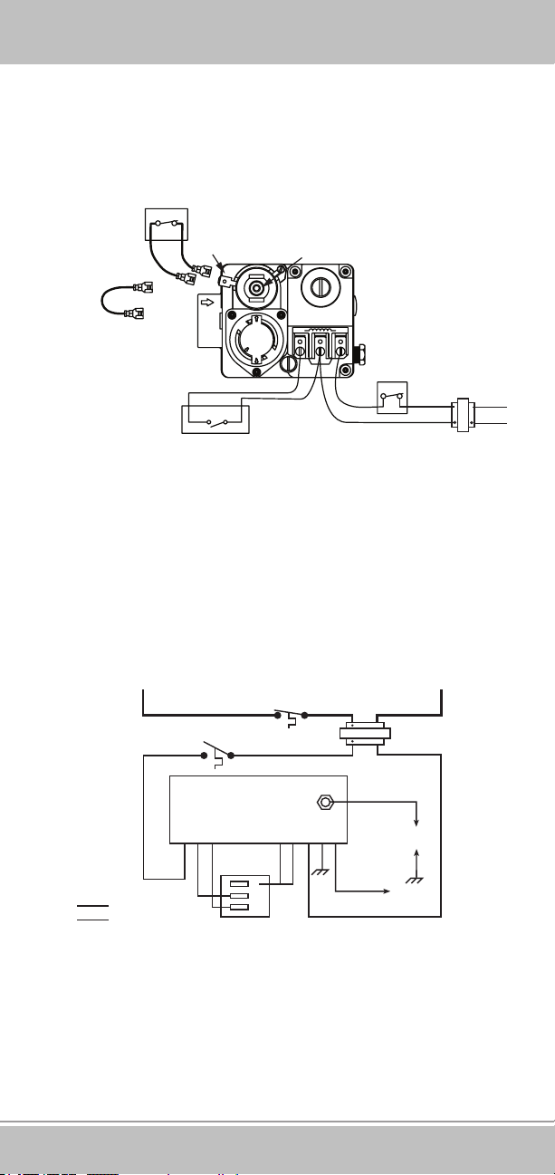
►System Applications
Hot Surface Ignition (HSI)
The thermostat calls for heat and energizes the HSI control. If
system is equipped with prepurge, the purge fan is energized and
power will be delayed thirty seconds before application to the Hot
Surface Ignitor. If prepurge is not selected, the ignitor is powered
within one second. The ignitor heats up and at the end of the
heating period, the redundant and main valves are opened. A
ame must be detected within a xed time period or both valves
close, the ignitor is turned off and the HSI control locks out unless
the system is equipped with retry. Retry indicates the ignition
sequence will be repeated for a total of three tries if ame is
undetected or lost within 30 seconds of ignition.
L
2
FLAME
PROBE
ALTERNATE
LIMIT
H
FPL
S
2
LIMIT
CONTROLLER
TRANSFORMER
1
RED
ADAPTER
H
S
1
BLUE
HOT
SURFACE
IGNITER
L1
(HOT)
L2
C
P
M
GAS
VALV E
External
Jumper
MV2
MV1
M
V
2
G
T
N
R
D
BURNER
GROUND
THERMOSTAT OR
CONTROLLER
M
T
V
H
1
Typical Wiring for Hot Surface Ignition System
Direct Spark Ignition (DSI)
The thermostat calls for heat and simultaneously energizes the
DSI control module and gas valve solenoid. Sparks at the ignition
electrodes ignite the gas at the main burner. Flame is sensed
through the electrodes by the ame detection circuit and shuts off
the sparking. If ame is not established within a xed time period
(lock-out time) main and redundant valves close, sparking ceases
and the control module locks out.
TR
MV
VAL
MV
(GND)
External
Jumper
MPC
GAS
VALV E
THERMOSTAT OR
CONTROLLER
Typical Wiring for Direct Spark Ignition System
TH
Burner Ground
ALTERNATE
LIMIT
FLY
GND
LEAD
FLAME
(GND)
TRANSFORMER
SPARK
CONTROLLER
SPARK
PROBE
FLAME
PROBE
LIMIT
L1 (HOT)
L2
8 Gas Valve Cross Reference
Page 9
►System Applications
Standing Pilot
Gas ow to the pilot burner is controlled by a safety valve which
is manually operated and held in by current generated from a
thermocouple placed in the pilot ame. When the thermostat
calls for heat the main valve is energized.
Electrical Cut Out (E.C.O.) Switch or
Supplementary Limit in appliance
ECO Terminals (2)
Jumper
Power Unit
NOTE: If appliance does not
have E.C.O. Switch
or supplementary limit,
jumper E.C.O. terminals
TH, TH-TR to Thermostat
W
Thermostat
ON
PILOT
OFF
R
PILOT
ADJ.
TRTH
TR
TH
TH-TR, TR to Transformer
24 VAC
Line
Transformer
Wiring for 36C03 (24 VAC) with E.C.O.
Proven Pilot
The thermostat calls for heat and simultaneously energizes the
pilot valve and the Proven Pilot control. Sparking from the ignition
electrode to the pilot burner ignites the gas at the pilot burner.
Flame is sensed by the ame detection circuit which energizes
the main valve. Main burner gas is ignited and sparking ceases
once a pilot ame is detected.
HOT
THPVM
V
LINE VOLTAGE
THERMOSTAT
LIMIT
MVPVT
120 VAC
25 VAC
H.V. LEAD
G
IGNITION
NDF
ELECTRODE
P
R
(PILOT)
NEUTRAL
COMMON (“C”)WR
Hot
C
LINE VOLTAGE
LOW VOLTAGE
P
M
SENSE
ELECTRODE
Typical Wiring for Proven/Intermittent Pilot System
Gas Valve Cross Reference 9
Page 10

62
62
►System Applications
Cycle Pilot System
The thermostat calls for heat and simultaneously energizes pilot
solenoid and pilot relight control. Pilot valve opens and relight
begins sparking. Gas ow activates the pressure switch. Sparks
ignite pilot gas. Once the ame is detected, the sparks stop.
After sufcient heat is sensed by the Mercury Flame Sensor, the
main valve is energized and the system is in operating mode.
(Fig. 1)
The schematic for “ALL GASES,” Figure 2, includes a safety
timer which acts to close the main gas valve, turns off the pilot
redundant coil and locks out the system should a ame not be
detected within a xed period of time.
MAIN COIL
PILOT
REDUNDANT
COIL
63254
T2 T1
5059
24 VAC
40VA
TRANSFORMER
LIMIT
LINE
NATURAL GAS
Figure 1
CYCLE PILOT HARNESSES
HARNESS
LENGTH
36”
36”
PRESSURE
SWITCH
TO ELECTRODE
THRU MOUNTING
HOLES
THERMOSTAT
54321
WIRING
HARNESS
TYPE NO.
F115-0059
F115-0064
3098 SENSOR
HOT
2
COLD
3
4
MAIN COIL
PILOT
REDUNDANT
COIL
63254
BLUE
54231
WARP
SWITCH
WARP SWITCH HEATER
24 VAC
RED
T2 T1
5059
LINE
PRESSURE
SWITCH
TAN
TO ELECTRODE
THRU MOUNTING
HOLES
LIMIT
THERMOSTAT
ALL GASES
YEL
Figure 2
5
34
1
3098 SENSOR
HOT
2
COLD
3
4
WIRING
HARNESS
ORG
SAFETY
TIMER
5022
T1T2
1
345
10 Gas Valve Cross Reference
Page 11

"N
►Product Features and Specifications
36C Series
Combination Gas Valve. The versatile 36C03 Series combination
gas valves cover a wide range of applications. Designed for use
with common ignition systems and standing pilots, it replaces
hundreds of existing models in the eld.
Features
• Standing Pilot • Adjustable regulator(s)
• Single Stage • Inlet/outlet screens
• Fast Opening • Line interrupter
• Max. Capacity @ • Inlet/outlet pressure taps
1” PD = 280,000 BTU/HR • CSA approved
• Convertible – natural or LP gas • Optional sidetaps
Specications
Electrical Rating........................................0.23 Amps @ 24 VAC
Other Voltage..................................................750 mV, 120 VAC
Operating Ambient Temperature .....-40° to 175°F (-40° to 79°C)
Pressure Rating (max.)................................ 1/2 PSI (14.0" W.C.)
Pilot Gas Connection ............................. 1/4" compression tting
Pressure Tap ..............................................................1/8" N.P.T.
3.375
SIDE OUTLETS
(PLUGGED)
4.200
SWING
RADIUS
INLET 3/4" – 14 NPT
(PLASTIC DUST
PLUG INSTALLED)
0.875
1.125
.875 .875
PILOT
1.437
2.875
0.562
VENT
PRESS
TAP
INLET PRESSURE TAP
1/8 - 27 N.P.T. THD.
OUTLET PRESSURE TAP
1/8 - 27 N.P.T. THD.
1.062
LEFT & RIGHT
SIDE OUTLETS
TAPPED 1/2" N.P.T.
& PLUGGED
(1/2" PIPE PLUGS)
5.169
1.156
INLET & OUTLET
3/4 - 14 N.P.T. THD.
1" PD Capacity
Nat. Gas
2.5" to 5.0"
Opening
Fast
Fast
Fast
Fast
Fast
Fast
Regulator
Adjustment
Range
7.5" to 12.0"
Regulator
Setting
3.5"
3.5"
3.5"
3.5"
3.5"
3.5"
LP Gas
Regulator
Adjustment
Range
2.5"-5.0"
2.5"-5.0"
2.5"-5.0"
2.5"-5.0"
2.5"-5.0"
2.5"-5.0"
Pipe Size
(36 C)
1/2" x 3/4"
3/4" x 3/4"
Model
Number
36C03-300
36C03-333
36C03-400
36C03-433
36C03U-333
36C03U-433
36C03A-410 120 VAC Fast 3.5" 2.5"-5.0
NAT GAS
0.64 Sp. Gr.
(1000 BTU/HR)
230,000
280,000
Typical
App.
Standing Pilot
Standing Pilot
Standing Pilot
Standing Pilot
Standing Pilot
Standing Pilot
LP GAS
1.53 Sp. Gr.
(2500 BTU/HR)
372,600
453,600
Type of
Voltage
24 VAC
Nat./LP
24 VAC
Nat./LP
24 VAC
Nat./LP
24 VAC
Nat./LP
750 mV
Nat./LP
750 mV
Nat./LP
Gas
Pipe
Size
1/2 x 3/4
1/2 x 3/4
3/4 x 3/4
3/4 x 3/4
1/2 x 3/4
3/4 x 3/4
3/4 x 3/4
Valve
Stages
Single
Stage
Characteristics
BTU/HR
PILOT
PLUG
OUTIN
ALL DIMENSIONS
IN INCHES
Side
Taps
No
Yes
Yes
Yes
Yes
Yes
oNat./LPStanding Pilot
Gas Valve Cross Reference 11
Page 12

4.200 R
►Product Features and Specifications
36H Series
Universal Replacement Electronic Ignition Gas Valve. The
versatile 36H Series combination gas valves cover a wide range
of applications. Designed for use with common ignition systems
(HSI/DSI/Proven Pilot), it replaces hundreds of existing models in
the eld. The 36H Series is our highest capacity combination gas
valve.
Features
• HSI/DSI/Proven Pilot • Inlet/outlet screens
• Single Stage/Two-Stage • Electric on-off switch
• Fast/Slow Opening • Inlet/outlet pressure taps
• Convertible – natural or LP Gas • CSA approved
• Adjustable regulator(s)
Specications
Electrical Rating.....................................0.41 amps (Single Stage)
0.54 amps (Two-Stage)
Voltage...............................................................................24 VAC
Frequency........................................................................50/60 Hz
Operating Ambient Temperature .........-40° to 175°F (-40°to 79°C)
Pressure Rating (max.)................................... 1/2 PSI (14.0" W.C.)
INLET 3/4" – 14 NPT
(PLASTIC DUST
PLUG INSTALLED)
0.031
Pipe Size
(36 H)
3/4" x 3/4"
1/2" x 3/4"
Model
Number
36H32-304
36H32-423
36H33-412
36H64-463
36H65-401
1.125
INLET PRESSURE TAP
1/8" – 27 NPT
1" PD Capacity
BTU/HR
NAT GAS
0.64 Sp. Gr.
(1000 BTU/HR)
300,000
260,000
Type of
Gas
Voltage
24 VAC
Nat./LP
24 VAC
Nat./LP
24 VAC
Nat./LP
24 VAC
Nat./LP
24 VAC
Nat./LP
1.375
3.259
1.53 Sp. Gr.
(2500 BTU/HR)
Pipe
Size
1/2 x 3/4
3/4 x 3/4
3/4 x 3/4
3/4 x 3/4
3/4 x 3/4
1.631
LP GAS
486,000
421,000
Characteristics
Opening
Fast
Fast
Slow
Fast
Slow
SWING RADIUS
1.375
Valve
Stages
Single
Stage
Two-
Stage
Stages
1
1
1
2
2
3.770
0.569
1.203
Adjustment
Nat. Gas
2.5" to 5.0"
1.0" – 3.5" Low
2.5" – 5.0" High
Proven
Pilot
HSI/DSI
Yes
Yes
Yes
Yes
Yes
Yes
Yes
Yes
Yes
Yes
Regulator
Range
8.0" – 12.0" High
Standing
4.0" – 9.5" Low
Pilot
3.984 INLET TO OUTLET
LP Gas
5.0" to 12.0"
Intermittent
Pilot
No
Yes
No
Yes
No
Yes
No
Yes
No
Yes
Convertible
Nat./LP
Kit Included
Yes
Yes
Yes
Yes
Yes
CENTERLINE OF
INLET & OUTLET
ALL DIMENSIONS
IN INCHES
Reducer
Bushing
Kit
Yes
Yes
Yes
Yes
Yes
PROVEN
PILOT PLUG
Inlet &
Outlet
Pressure Tap
Yes
Yes
Yes
Yes
Yes
12 Gas Valve Cross Reference
Page 13

►Product Features and Specifications
36J Series
Replacement Electronic Ignition Gas Valve. The versatile 36J
series combination gas valves cover a wide range of applications. Designed for use with common ignition systems (HSI/DSI),
it replaces hundreds of existing models in the eld.
Features
• HSI/DSI • Inlet/outlet screens
• Single Stage/Two-Stage • Electric on-off switch
• Fast/Slow Opening • Inlet/outlet pressure taps
• Convertible – natural or LP Gas • CSA approved
• Adjustable regulator(s)
Specications
Electrical Rating.....................................0.28 amps (Single Stage)
0.43 amps (Two-Stage)
Voltage............................................................................... 24 VAC
Frequency........................................................................ 50/60 Hz
Operating Ambient Temperature .........-40° to 175°F (-40°to 79°C)
Pressure Rating (max.)....................................1/2 PSI (14.0" W.C.)
4.243
1.250
Pipe Size
(36 J)
Pipe Size
(36 J)
1/2" x 1/2"
1/2" x 1/2"
1/2" x 1/2"
1/2" x 1/2"
Model
Number
36J22-214
36J24-214
36J54-214
36J55-214
36J24-614
36J55-614
2.750
SWING
RADIUS
0.64 Sp. Gr.
(1000 BTU/HR)
Voltage
24 VAC
24 VAC
24 VAC
24 VAC
24 VAC
24 VAC
1.329
INLET - 1/2" N.P.T.
(PLASTIC DUST PLUG INSTALLED)
1" PD Capacity
BTU/HR
NAT GAS
140,000
140,000
Type of
Gas
Nat./LP
Nat./LP
Nat./LP
Nat./LP
Nat./LP
Nat./LP
LP GAS
1.53 Sp. Gr.
(2500 BTU/HR)
226,800
226,800
Pipe
Size
Characteristics
1/2 x 1/2
1/2 x 1/2
1/2 x 1/2
2-Stage – Fast
1/2 x 1/2
2-Stage – Slow
1/2 x 1/2
1/2 x 1/2
2-Stage – Slow
Opening
SWITCH
(SHIPPED IN "ON" POSITION)
0.500
Valve
Stages
Valve
Stages
Single
Single
2.5" to 5.0"
Stage
Stage
1.0" – 4.0" Low
Two-
2.0" – 5.0" High
Stage
Regulator
Convertible
Setting
Fast
3.5"
Slow
3.5"
LO 1.5" – HI 3.5"
LO 1.5" – HI 3.5"
Slow
3.5"
LO 1.5" – HI 3.5"
Nat. Gas
Nat./LP
Yes
Yes
Yes
Yes
Yes
Yes
Regulator
Adjustment
Range
4.0" – 10.0" Low
6.0" – 12.0" High
LP
Conversion
Kit Included
Yes
Yes
Yes
Yes
Yes
Yes
4.693
LP Gas
7.0" to 12.0"
90° Bottom Outlet
90° Bottom Outlet
Flow
Direction
Str. Thru
Str. Thru
Str. Thru
Str. Thru
Reducer
Bushing
Kit
Yes
Yes
Yes
Yes
No
No
Filter
Screen
Yes
Yes
Yes
Yes
Yes
Yes
ALL DIMENSIONS
IN INCHES
Inlet
Outlet
Pressure
Pressure
Tap
Taps
Yes
Yes
Yes
Yes
Yes
Yes
Yes
Yes
Yes
Yes
Yes
Yes
Gas Valve Cross Reference 13
Page 14

►Product Accessories
36C Series
ACCESSORIES
Model Number Regulator Conversion Kits Available
F92-0656 LP to NAT GAS (2.5”–5.0”)
F92-0659 NAT to LP GAS (7.5”–12.0”)
F92-0737 NAT to LP GAS (Non-regulated)
F92-0866 NAT to LP GAS (4.2”–11.0”)
F92-0727
F92-0514
36H Series
Model Number Regulator Conversion Kits
F92-0659 Natural Gas to LP Single Stage
F92-1008 Natural Gas to LP Two-Stage
F92-0656 LP to Natural Gas Single Stage
F92-1011 LP to Natural Gas Two-Stage
1/4” brass compression tting for pilot line conversions
One 3/4” x 1/2” N.P.T. and one 1/2” x 3/8” N.P.T.
reducer bushings
ACCESSORIES
36J Series
ACCESSORIES
Model Number Regulator Conversion Kits
F92-0659 Natural Gas to LP Single Stage
F92-0737
F92-1008 Natural Gas to LP Two-Stage
F92-0656 LP to Natural Gas Single Stage
F92-1011 LP to Natural Gas Two-Stage
F27-0373 Flange Mount Kit Single or Two-Stage
F115-0228 Wire Harness for Two-Stage
14 Gas Valve Cross Reference
Natural Gas to
Unregulated LP
Adapter
Single Stage
Page 15

►Cross Reference
OEM NO. WR NO.
00 880208 36C03A-410
00 880209 36C03A-410
00001005570 36H32-304
00001008753 36J24-214
00001160253 36C03-433
00001162470 36C94-303
00001585980 36H32-304
0002-42-013 36C03U-333
0002-42-015 36C01A-405
0002-42-016 36C01-405
0002-42-098 36H32-304
0002-42-099 36C01A-405
0002-42-100 36C01-405
0002-42-169 36J55-214
0002-42-174 36J24-214
00-497271-00001 36C03U-333
00-497271-00002 36C03U-333
00-497271-00003 36H32-423
00-497271-00004 36H32-423
00-497271-00005 36C03-300
00-497271-00006 36C03-300
00-497271-00007 36H32-423
00-497271-00008 36H32-423
0050009 36H32-423
0050010 36H32-304
0050011 36H32-423
0050140 36H32-304
00-817362-00000 36C94-907
00-817362-00002 36C94-907
00-840126 36C03A-410
00-851315-00001 36H32-423
00-880208 36C03A-410
01-1000V9-00126 36H32-423
01-1000V9-00181 36H32-423
013010 36H32-423
0151F00000P 36J54-214
0151L00000 36H64-463
02-1549 36C74-913
025-20289-000 36H32-423
025-20289-700 36H32-423
025-22677-000 36C84-912
025-22677-700 36C84-912
025-23001-000 36C84-921
025-23014-700 36C03-433
025-25421-000 36C84-921
025-25421-700 36C84-921
025-25437-000 36H32-304
025-25437-700 36H32-304
025-26372-000 36H64-463
025-26372-700 36H64-463
025-26373-000 36H64-463
025-26373-700 36H64-463
025-27515 36H64-463
025-27515-000 36H64-463
025-27515-700 36H64-463
025-27660-000 36H32-304
025-27660-700 36H32-304
02527720700 36H32-423
025-27769-000 36H32-304
025-27769-700 36H32-304
025-27918-000 36H64-463
025-27918-700 36H64-463
025-29017-000 36H32-304
025-29017-700 36H32-304
025-30105-000 36H32-304
OEM NO. WR NO. OEM NO. WR NO.
025-30164-000 36J24-214
025-30164-700 36J24-214
025-30167-700 36J24-214
025-30251-000 36J24-214
025-30251-700 36J24-214
025-30719-000 36H32-304
025-30719-700 36H32-304
025-30789-000 36J24-214
02530836000 36C03-433
025-30836-700 36C03-433
025-30838-000 36H32-423
025-30838-700 36H32-423
025-30839-000 36H64-463
025-30839-700 36H64-463
025-30841-000 36C84-921
025-30841-700 36C84-921
025-30843-000 36H32-304
025-30888-000 36H33-412
025-30888-700 36H33-412
025-31969-000 36H33-412
025-31996-000 36H33-412
025-31996-700 36H33-412
025-32676-000 36H64-463
025-32794-000 36H32-304
025-33334-000 36H65-401
025-35316-000 36J24-214
025-35317-000 36J24-214
025-35394-000 36J54-214
025-35395-000 36J54-214
025-37426-000 36J24-214
025-38915-000 36J54-214
025-38974-000 36J24-214
025-38979-000 36J22-214
025-90888-000 36H33-412
029-18977-700 36C84-912
05-151100 36C03A-410
05-151101 36C03-400
05-151200 36C03U-433
056289 36H32-423
071278501 36H32-423
078557-000 36C04U-438
078557-001 36C04U-438
08-5055 36H33-412
08-7126 36H32-304
091193 36H32-423
096300 36C03-433
096309 36H32-423
096311 36H32-423
100099 36C03-300
100100 36C03-400
1001349 36H32-304
1002701 36H32-304
10027236 36H64-463
1005570 36H32-304
1005570U 36H32-304
1005571 36H32-304
10060566 36H32-423
1006221 36H64-463
1006377 36H32-304
1008753U 36J24-214
1008754 36J24-214
1008960 36H32-304
1008960U 36H32-304
1008961 36H32-304
1012455 36H32-423
10212777 36C84-926
10289653 36C03-433
10332112 36C03U-333
10333457 36C74-913
10356647 36C01A-405
10360950 36H32-423
10446621 36H32-423
10568 36C03A-410
10569 36C03A-410
105782 36H64-463
1057821 36H64-463
10602631 36H64-463
1070690 36H64-463
1071324 36H64-463
10P5001 36C03-333
10P9001 36C03-433
110502-G1 36C03U-333
110502-G2 36C03U-333
110761-4 36C03U-333
1149482 36C74-913
1149646 36C84-921
1149696 36C84-921
1149781 36C03-333
1149848 36H64-463
1160185U 36C94-907
1160253 36C03-433
1162470 36C94-303
1162544 36H32-304
1177542 36J54-214
1179698 36J54-214
1180634 36J54-214
1180955 36J54-214
11J28-00381-002 36C03-433
11J28-00742 36H32-423
11J28-02454-001 36H64-463
11J28-02454-003 36H64-463
11J28-06892-001 36J22-214
11J28-06892-002 36J22-214
11J28-06893-001 36H32-423
11J28-06893-002 36H32-423
11J28-06894-001 36J54-214
11J28-06894-002 36J54-214
11J28-06895-001 36H64-463
11J28-06895-002 36H64-463
120032 36C03U-333
120-06622 36H32-304
120-06821 36H32-304
120-09318 36J22-214
120-09319 36J22-214
1200AMVR 36C03U-333
1200BGVE 36C03-300
1200BGVEM 36C03-300
1210AMVR 36C03U-333
1210BGVE 36C03-300
1210BGVEM 36C03-300
12191|004 36C03U-333
126508 36J22-214
12654 36J54-214
128099 36H32-423
12858 36J24-214
128927 36H32-304
128928 36H32-423
12908 36J22-214
12L5701 36H64-463
13005075 36H32-304
For complete cross reference information, refer to Model Number Search at www.white-rodgers.com
Cross Reference
Gas Valve Cross Reference 15
Page 16

►Cross Reference
OEM NO. WR NO. OEM NO. WR NO. OEM NO. WR NO.
13005223 36H32-304
1300-5223 36J22-214
13006223 36J22-214
130280 36J24-214
1353473 36C84-913
140006 36C03A-410
140026 36H32-423
150 36H32-423
1500989701 36H32-423
1500989801 36H32-423
1503029301 36H32-423
1503029401 36H32-423
1503032101 36H32-423
1503033001 36H32-423
1503072001 36H32-423
1503072101 36H32-423
1503072201 36H32-423
1503072301 36H32-423
15659A 36J22-214
157167 36H32-423
157168 36H32-423
1585956 36C03-433
Cross Reference
1585975 36H32-304
1585980 36H32-304
1585981 36H32-304
1585981U 36H32-304
1585-982 36C74-913
1585987 36J24-214
1585988 36H32-304
161222 36J24-214
16239 36J22-214
17583 36H32-304
17597 36J22-214
17624 36J54-214
17625 36J54-214
17629 36J24-214
182052-001 36H32-304
184032 36J54-214
18654A 36J54-214
18655A 36J54-214
192454-000 36H32-423
192454-001 36H32-423
192454-002 36H32-423
192454-003 36H32-423
192827-000 36C74-913
192827-002 36C74-913
192966-000 36H32-423
192967-000 36H32-423
194406-001 36C74-913
196632-000 36H32-423
197282-000 36H33-412
197282-001 36H33-412
197738-000 36H32-423
197738-001 36H32-423
197738-002 36H32-423
197738-003 36H32-423
1D279 36H32-304
1RC51 36C03-300
1RC52 36H64-463
1RC53 36H64-463
1YRN7 36H32-423
1YRN8 36H64-463
2000IPERHC 36H32-304
2022-0192 36H32-423
20466803 36J22-214
For complete cross reference information, refer to Model Number Search at www.white-rodgers.com
20-5026 36J22-214
20937951 36C53-418
21166 36H32-304
215-402 36C03-300
215-404 36C03-300
21J7601 36H32-304
21J7701 36H64-463
21J8801 36H64-463
21P5901 36C84-913
2206-120 36H32-304
221525 36H32-423
240006526 36J54-214
24-103 36H32-423
2475275 36C84-912
2504-130 36C21-411
2504-131 36C21-411
2504-132 36C21-411
2504-133 36C21-411
2504-141 36C21-411
2504-142 36C21-411
2504-143 36C21-411
2504-151 36C21-411
2504-152 36C21-411
2504-203 36C21-411
2504-204 36C21-411
2504-205 36C21-411
2504-206 36C21-411
2504-207 36C21-411
2504-208 36C21-411
2504-209 36C21-411
2504-23 36C21-411
2504-264 36C21-411
2504-284 36C21-411
2504-286 36C21-411
2504-288 36C21-411
2504-31 36C21-411
2504-32 36C21-411
2504-33 36C21-411
2504-35 36C21-411
2504-36 36C21-411
2504-41 36C21-411
2504-42 36C21-411
2509-131 36C21-411
2509-132 36C21-411
2509-133 36C21-411
2509-134 36C21-411
2509-135 36C21-411
2509-141 36C21-411
2509-151 36C21-411
2509-152 36C21-411
2509-153 36C21-411
2509-203 36C21-411
2509-204 36C21-411
2509-205 36C21-411
2509-206 36C21-411
2509-207 36C21-411
2509-208 36C21-411
2509-218 36C21-411
2509-234 36C21-411
2509-238 36C21-411
2509-253 36C21-411
2509-254 36C21-411
2509-256 36C21-411
2509-258 36C21-411
2509-263 36C21-411
2509-264 36C21-411
2509-266 36C21-411
2509-274 36C21-411
2509-276 36C21-411
2509-278 36C21-411
2509-30 36C21-411
2509-31 36C21-411
2509-314 36C21-411
2509-32 36C21-411
2509-33 36C21-411
2509-34 36C21-411
2509-35 36C21-411
2509-36 36C21-411
2527720700 36H32-423
2529-1 36C21-411
2529-103 36C21-411
2529-2 36C21-411
2529-21 36C21-411
2529-22 36C21-411
2529-26 36C21-411
2529-3 36C21-411
2541090000 36H64-463
2571-30 36C21-411
2571-31 36C21-411
2571-32 36C21-411
2571-35 36C21-411
2571-36 36C21-411
2571-51 36C21-411
2572-31 36C21-411
2572-32 36C21-411
25A11-126 36C21-411
25A11-223 36C21-411
25A11-227 36C21-411
25A21-11 36C21-411
25A21-6 36C21-411
25A22-10 36C21-411
25A22-52 36C21-411
25A22-7 36C21-411
25D03-214 36C21-411
25D03-216 36C21-411
25D03-218 36C21-411
25D03-224 36C21-411
25D03-226 36C21-411
25D03-228 36C21-411
25D03-234 36C21-411
25D03-236 36C21-411
25D03-238 36C21-411
25G01-104 36C21-411
25G01-203 36C21-411
25G01-204 36C21-411
25G01-205 36C21-411
25G01-206 36C21-411
25G01-207 36C21-411
25G01-208 36C21-411
25G01-214 36C21-411
25G01-24 36C21-411
25G01-253 36C21-411
25G01-254 36C21-411
25G01-255 36C21-411
25G01-256 36C21-411
25G01-257 36C21-411
25G01-258 36C21-411
25G01-284 36C21-411
25G01-286 36C21-411
25G01-288 36C21-411
16 Gas Valve Cross Reference
Page 17

►Cross Reference
OEM NO. WR NO. OEM NO. WR NO. OEM NO. WR NO.
25G01-3 36C21-411
25G01-303 36C21-411
25G01-304 36C21-411
25G01-306 36C21-411
25G01-308 36C21-411
25G01-326 36C21-411
25G01-394 36C21-411
25G01-396 36C21-411
25G01-4 36C21-411
25G01-5 36C21-411
25G01-6 36C21-411
25G01-7 36C21-411
25G01-8 36C21-411
25G03-104 36C21-411
25G03-203 36C21-411
25G03-204 36C21-411
25G03-205 36C21-411
25G03-206 36C21-411
25G03-207 36C21-411
25G03-208 36C21-411
25G03-24 36C21-411
25G03-253 36C21-411
25G03-254 36C21-411
25G03-255 36C21-411
25G03-256 36C21-411
25G03-257 36C21-411
25G03-258 36C21-411
25G03-3 36C21-411
25G03-4 36C21-411
25G03-403 36C21-411
25G03-404 36C21-411
25G03-405 36C21-411
25G03-406 36C21-411
25G03-407 36C21-411
25G03-408 36C21-411
25G03-453 36C21-411
25G03-454 36C21-411
25G03-455 36C21-411
25G03-456 36C21-411
25G03-457 36C21-411
25G03-458 36C21-411
25G03-484 36C21-411
25G03-486 36C21-411
25G03-488 36C21-411
25G03-5 36C21-411
25G03-6 36C21-411
25G03-7 36C21-411
25G03-8 36C21-411
25G05-104 36C21-411
25G05-203 36C21-411
25G05-204 36C21-411
25G05-205 36C21-411
25G05-206 36C21-411
25G05-207 36C21-411
25G05-208 36C21-411
25G05-24 36C21-411
25G05-3 36C21-411
25G05-4 36C21-411
25G05-5 36C21-411
25G05-6 36C21-411
25G05-7 36C21-411
25G05-8 36C21-411
25J5901 36J24-214
25K4401 36J24-214
26236 36J22-214
For complete cross reference information, refer to Model Number Search at www.white-rodgers.com
26A01-1 36C21-411
26A01-12 36C21-411
26A01-2 36C21-411
26A01-204 36C21-411
26A01-205 36C21-411
26A01-206 36C21-411
26A01-207 36C21-411
26A01-208 36C21-411
26A01-209 36C21-411
26A01-23 36C21-411
26A01-3 36C21-411
26A01-71 36C21-411
26A02-1 36C21-411
26A02-2 36C21-411
26A02-204 36C21-411
26A02-205 36C21-411
26A02-206 36C21-411
26A02-207 36C21-411
26A02-208 36C21-411
26A02-209 36C21-411
26A02-22 36C21-411
26A02-3 36C21-411
26A05-1 36C21-411
26A05-2 36C21-411
26A05-254 36C21-411
26A05-255 36C21-411
26A05-256 36C21-411
26A05-257 36C21-411
26A05-258 36C21-411
26A05-259 36C21-411
26A05-3 36C21-411
26A11-1 36C21-411
26A11-11 36C21-411
26A11-2 36C21-411
26A11-3 36C21-411
26A12-1 36C21-411
26A12-2 36C21-411
26A12-3 36C21-411
2702-328 36H32-304
28G1401 36J22-214
28G2601 36H64-463
28G3001 36H64-463
28G7901 36H32-423
2C-T75 36C03U-433
2E228 36C21-411
2E229 36C21-411
2E401 36C03U-433
2E402 36C03-433
2E520 36C03-433
2E725 36C03-333
2E726 36C03-333
2E791 36C03-300
2E854 36C03U-333
300012109 36H64-463
3004-1301 36J22-214
30287 36J22-214
30455 36J54-214
30767 36J54-214
3079498 36C84-926
3134731 36C04U-438
31742 36H65-401
31L3701 36H33-412
3224581 36C03A-410
3330966 36C01-405
341062 36H64-463
341063 36H32-423
341073 36J54-214
3601-124 36C03-333
3601-128 36C03-333
3601-188 36C03-333
3601-208 36C03-333
3601-228 36C03-333
3601-248 36C03-333
3601-288 36C03-333
3601-404 36C03-333
3601-424 36C03-333
3601-426 36C03-333
3601-428 36C03-333
3601-486 36C03-333
3601-488 36C03-333
3601-505 36C03-333
3601-508 36C03-333
3601-528 36C03-333
3601-584 36C03-333
3601-588 36C03-333
3601A-305 36C03A-410
3601A-325 36C03A-410
3601A-329 36C03A-410
3601A-605 36C03A-410
3601A-625 36C03A-410
3601A-685 36C03A-410
3602-124 36C03-333
3602-128 36C03-333
3602-208 36C03-333
3602-224 36C03-333
3602-228 36C03-333
3602-584 36C03-333
3603-208 36C03-333
3603-228 36C03-333
3604-118 36C03-333
3604-228 36C03-333
3604-404 36C03-333
3604-408 36C03-333
3604-428 36C03-333
3604-484 36C03-333
3604-518 36C03-333
3604-528 36C03-333
3605-925 36C03-333
3606-128 36C03-333
3606-188 36C03-333
3606-228 36C03-333
3606-486 36C03-333
3606-488 36C03-333
3606-528 36C03-333
3606A-329 36C03A-410
3641-228 36C03-333
3641-428 36C03-333
3644-118 36C03-333
3644U-228 36C03U-333
3646-428 36C03-333
36607 36J54-214
3661-128 36C03-333
3661-28 36C03-333
3661-288 36C03-333
3661-428 36C03-333
3661-488 36C03-333
3661-505 36C03-333
3661-506 36C03-333
3661-583 36C03-333
3661-584 36C03-333
Cross Reference
Gas Valve Cross Reference 17
Page 18

►Cross Reference
OEM NO. WR NO. OEM NO. WR NO. OEM NO. WR NO.
3661-588 36C03-333
3661-628 36C03-333
3661-688 36C03-333
3661-82 36C03-333
3661-83 36C03-333
3661-86 36C03-333
3661A-625 36C03A-410
3661A-626 36C03A-410
3661A-629 36C03A-410
3661A-685 36C03A-410
3661A-686 36C03A-410
3661U-228 36C03U-333
3661U-288 36C03U-333
3661U-508 36C03U-333
3661U-528 36C03U-333
3661U-588 36C03U-333
3662-584 36C03-333
3666-128 36C03-333
3666-404 36C03-333
3666-428 36C03-333
3666-488 36C03-333
3666-506 36C03-333
Cross Reference
3666-584 36C03-333
3666-588 36C03-333
3666-83 36C03-333
3666-86 36C03-333
3666A-629 36C03A-410
3666U-228 36C03U-333
3666U-288 36C03U-333
36C01-200 36C01-405
36C01-201 36C01-405
36C01-204 36C01-405
36C01-212 36C01-405
36C01-215 36C01-405
36C01-217 36C01-405
36C01-275 36C01-405
36C01-282 36C01-405
36C01-283 36C01-405
36C01-300 36C01-405
36C01-301 36C01-405
36C01-302 36C01-405
36C01-303 36C01-405
36C01-400 36C01-405
36C01-403 36C01-405
36C01-405 36C01-405
36C01A-201 36C01A-405
36C01A-202 36C01A-405
36C01A-206 36C01A-405
36C01A-210 36C01A-405
36C01A-212 36C01A-405
36C01A-283 36C01A-405
36C01A-284 36C01A-405
36C01A-404 36C01A-405
36C01A-405 36C01A-405
36C01A-475 36C01A-405
36C03-100 36C03-333
36C03-103 36C03-333
36C03-133 36C03-333
36C03-200 36C03-333
36C03-205 36C03-433
36C03-210 36C03-333
36C03-211 36C03-433
36C03-216 36C03-333
36C03-219 36C03-333
36C03-221 36C03-333
For complete cross reference information, refer to Model Number Search at www.white-rodgers.com
36C03-222 36C03-433
36C03-228 36C03-333
36C03-230 36C03-433
36C03-233 36C03-333
36C03-234 36C03-333
36C03-236 36C03-333
36C03-245 36C03-433
36C03-251 36C03-433
36C03-252 36C03-333
36C03-253 36C03-433
36C03-255 36C03-433
36C03-258 36C03-433
36C03-263 36C03-333
36C03-264 36C03-433
36C03-267 36C03-333
36C03-283 36C03-300
36C03-284 36C03-300
36C03-285 36C03-300
36C03-300 36C03-300
36C03-302 36C03-433
36C03-305 36C03-333
36C03-306 36C03-433
36C03-309 36C03-333
36C03-310 36C03-333
36C03-311 36C03-333
36C03-313 36C03-433
36C03-314 36C03-433
36C03-315 36C03-333
36C03-316 36C03-333
36C03-319 36C03-433
36C03-320 36C03-333
36C03-322 36C03-433
36C03-323 36C03-300
36C03-324 36C03-333
36C03-333 36C03-333
36C03-350 36C03-333
36C03-358 36C03-433
36C03-400 36C03-400
36C03-409 36C03-433
36C03-410 36C03-433
36C03-416 36C03-433
36C03-418 36C03-433
36C03-422 36C03-433
36C03-425 36C03-433
36C03-431 36C03-433
36C03-433 36C03-433
36C03-434 36C03-433
36C03-441 36C03-433
36C03-442 36C03-433
36C03-445 36C03-433
36C03-446 36C03-433
36C03-448 36C03-433
36C03-450 36C03-433
36C03-457 36C03-433
36C03-459 36C03-433
36C03-603 36C03-433
36C03-604 36C03-433
36C03-676 36C03-433
36C03A-100 36C03A-410
36C03A-200 36C03A-410
36C03A-202 36C03A-410
36C03A-210 36C03A-410
36C03A-220 36C03A-410
36C03A-260 36C03A-410
36C03A-266 36C03A-410
36C03A-271 36C03A-410
36C03A-300 36C03A-410
36C03A-310 36C03A-410
36C03A-400 36C03A-410
36C03A-410 36C03A-410
36C03A-432 36C03A-410
36C03A-436 36C03A-410
36C03A-437 36C03A-410
36C03U-100 36C03U-333
36C03U-102 36C03U-333
36C03U-108 36C03U-333
36C03U-113 36C03U-333
36C03U-115 36C03U-333
36C03U-200 36C03U-333
36C03U-204 36C03U-333
36C03U-210 36C03U-333
36C03U-218 36C03U-333
36C03U-231 36C03U-333
36C03U-273 36C03U-333
36C03U-282 36C03U-333
36C03U-284 36C03U-333
36C03U-285 36C03U-333
36C03U-300 36C03U-333
36C03U-310 36C03U-333
36C03U-330 36C03U-333
36C03U-333 36C03U-333
36C03U-339 36C03U-333
36C03U-340 36C03U-433
36C03U-350 36C03U-333
36C03U-400 36C03U-433
36C03U-401 36C03U-433
36C03U-403 36C03U-433
36C03U-409 36C03U-433
36C03U-410 36C03U-433
36C03U-430 36C03U-433
36C03U-433 36C03U-433
36C03U-450 36C03U-433
36C04U-301 36C04U-438
36C04U-310 36C04U-438
36C04U-312 36C04U-438
36C04U-415 36C04U-438
36C04U-419 36C04U-438
36C04U-422 36C04U-438
36C04U-423 36C04U-438
36C04U-438 36C04U-438
36C10-100 36C03-333
36C10-102 36C03-333
36C10-132 36C03-333
36C10-133 36C03-333
36C10-200 36C03-333
36C10-202 36C03-333
36C10-205 36C03-333
36C10-206 36C03-333
36C10-208 36C03-333
36C10-276 36C03-333
36C10-277 36C03-333
36C10-278 36C03-333
36C10-300 36C03-333
36C10-302 36C03-333
36C10-304 36C03-333
36C10-400 36C03-433
36C10-402 36C03-433
36C10A-100 36C03A-410
36C10A-101 36C03A-410
36C10A-200 36C03A-410
18 Gas Valve Cross Reference
Page 19

►Cross Reference
OEM NO. WR NO. OEM NO. WR NO. OEM NO. WR NO.
36C10A-209 36C03A-410
36C10A-276 36C03A-410
36C10A-300 36C03A-410
36C10A-400 36C03A-410
36C10A-402 36C03A-410
36C10U-100 36C03U-333
36C10U-200 36C03U-333
36C10U-211 36C03U-333
36C10U-276 36C03U-333
36C10U-400 36C03U-433
36C11-200 36C01-405
36C11-207 36C01-405
36C11-275 36C01-405
36C11-402 36C01-405
36C11A-201 36C01A-405
36C11A-202 36C01A-405
36C11A-206 36C01A-405
36C11A-207 36C01A-405
36C13-100 36C03-333
36C13-200 36C03-333
36C13-202 36C03-433
36C13-214 36C03-333
36C13-219 36C03-433
36C13-221 36C03-433
36C13-276 36C03-333
36C13-300 36C03-333
36C13-301 36C03-433
36C13-303 36C03-433
36C13-305 36C03-433
36C13-306 36C03-433
36C13-307 36C03-433
36C13-350 36C03-333
36C13-400 36C03-333
36C13-408 36C03-433
36C13-409 36C03-433
36C13-410 36C03-433
36C13-411 36C03-433
36C13A-200 36C03A-410
36C13A-215 36C03A-410
36C13A-222 36C03A-410
36C13A-275 36C03A-410
36C13A-276 36C03A-410
36C13A-406 36C03A-410
36C13U-103 36C03U-333
36C13U-108 36C03U-333
36C13U-115 36C03U-333
36C13U-116 36C03U-333
36C13U-117 36C03U-333
36C13U-200 36C03U-333
36C13U-213 36C03U-333
36C13U-214 36C03U-333
36C13U-227 36C03U-333
36C13U-276 36C03U-333
36C13U-300 36C03U-333
36C13U-305 36C03U-333
36C13U-319 36C03U-333
36C13U-330 36C03U-333
36C13U-350 36C03U-333
36C13U-407 36C03U-433
36C21-400 36C21-411
36C21-410 36C21-411
36C21-411 36C21-411
36C24-200 36C01-405
36C24-202 36C01-405
36C24-300 36C01-405
For complete cross reference information, refer to Model Number Search at www.white-rodgers.com
36C24-301 36C01-405
36C24-401 36C01-405
36C53-200 36C53-418
36C53-213 36C53-418
36C53-222 36C53-418
36C53-237 36C53-418
36C53-300 36C53-418
36C53-305 36C53-418
36C53-307 36C53-418
36C53-313 36C53-418
36C53-400 36C53-418
36C53-407 36C53-418
36C53-415 36C53-418
36C53-418 36C53-418
36C54-201 36C53-418
36C54-301 36C53-418
36C68-200 36H32-423
36C68-202 36H32-423
36C68-205 36H32-423
36C68-209 36H32-423
36C68-212 36H32-423
36C68-217 36H32-423
36C68-218 36H32-423
36C68-243 36H32-423
36C68-261 36H32-423
36C68-262 36H32-423
36C68-266 36H32-423
36C68-301 36H32-423
36C68-303 36H32-423
36C68-324 36H32-423
36C68-325 36H32-423
36C68-326 36H32-423
36C68-327 36H32-423
36C68-330 36H32-423
36C68-334 36H32-423
36C68-400 36H32-423
36C68-403 36H32-423
36C68-404 36H32-423
36C68-405 36H32-423
36C68-415 36H32-423
36C68-418 36H32-423
36C68-419 36H32-423
36C68-423 36H32-423
36C68-426 36H32-423
36C68-434 36H32-423
36C68-441 36H32-423
36C68-442 36H32-423
36C68-445 36H32-423
36C68-448 36H32-423
36C68-452 36H32-423
36C68-457 36H32-423
36C68-464 36H32-423
36C68-472 36H32-423
36C68-473 36H32-423
36C68-477 36H32-423
36C68-478 36H32-423
36C68-479 36H32-423
36C68-480 36H32-423
36C68-482 36H32-423
36C68-483 36H32-423
36C68-484 36H32-423
36C68-502 36H32-423
36C68-518 36H32-423
36C68-559 36H32-423
36C68-601 36H32-423
36C68-602 36H32-423
36C68-606 36H32-423
36C68-607 36H32-423
36C68-725 36H32-423
36C68-806 36H32-423
36C68-808 36H32-423
36C68-809 36H32-423
36C68-811 36H32-423
36C68-812 36H32-423
36C68-813 36H32-423
36C68-814 36H32-423
36C68-815 36H32-423
36C68-816 36H32-423
36C68-817 36H32-423
36C68-818 36H32-423
36C68-819 36H32-423
36C68-820 36H32-423
36C68-821 36H32-423
36C68-822 36H32-423
36C68-876 36H32-423
36C68-877 36H32-423
36C68-878 36H32-423
36C68-879 36H32-423
36C68-904 36H32-423
36C68-908 36H32-423
36C68-916 36H32-423
36C68-917 36H32-423
36C68-918 36H32-423
36C68-919 36H32-423
36C68-922 36H32-423
36C68-923 36H32-423
36C68-926 36H32-423
36C68-941 36H32-423
36C68-942 36H32-423
36C68-948 36H32-423
36C68-952 36H32-423
36C68-966 36H32-423
36C68-970 36H32-423
36C68-976 36H32-423
36C68-977 36H32-423
36C68-979 36H32-423
36C68-985 36H32-423
36C74-104 36C74-913
36C74-205 36C74-913
36C74-215 36C74-913
36C74-217 36C74-913
36C74-241 36C74-913
36C74-242 36C74-913
36C74-305 36C74-913
36C74-313 36C74-913
36C74-321 36C74-913
36C74-408 36C74-913
36C74-413 36C74-913
36C74-415 36C74-913
36C74-417 36C74-913
36C74-427 36C74-913
36C74-428 36C74-913
36C74-431 36C74-913
36C74-433 36C74-913
36C74-435 36C74-913
36C74-436 36C74-913
36C74-437 36C74-913
36C74-441 36C74-913
36C74-442 36C74-913
36C74-443 36C74-913
Cross Reference
Gas Valve Cross Reference 19
Page 20

►Cross Reference
OEM NO. WR NO. OEM NO. WR NO. OEM NO. WR NO.
36C74-474 36C74-913
36C74-475 36C74-913
36C74-505 36C74-913
36C74-913 36C74-913
36C76-205 36H64-463
36C76-210 36H64-463
36C76-214 36H64-463
36C76-225 36H64-463
36C76-227 36H64-463
36C76-230 36H64-463
36C76-234 36H64-463
36C76-235 36H64-463
36C76-314 36H64-463
36C76-318 36H64-463
36C76-401 36H64-463
36C76-406 36H64-463
36C76-407 36H64-463
36C76-408 36H64-463
36C76-411 36H64-463
36C76-412 36H64-463
36C76-413 36H64-463
36C76-417 36H64-463
Cross Reference
36C76-420 36H64-463
36C76-424 36H64-463
36C76-425 36H64-463
36C76-426 36H64-463
36C76-427 36H64-463
36C76-428 36H64-463
36C76-435 36H64-463
36C76-436 36H64-463
36C76-442 36H64-463
36C76-445 36H64-463
36C76-448 36H64-463
36C76-449 36H64-463
36C76-450 36H64-463
36C76-452 36H64-463
36C76-455 36H64-463
36C76-458 36H64-463
36C76-459 36H64-463
36C76-460 36H64-463
36C76-461 36H64-463
36C76-462 36H64-463
36C76-463 36H64-463
36C76-464 36H64-463
36C76-467 36H64-463
36C76-468 36H64-463
36C76-469 36H64-463
36C76-470 36H64-463
36C76-471 36H64-463
36C76-472 36H64-463
36C76-473 36H64-463
36C76-477 36H64-463
36C76-478 36H64-463
36C76-479 36H64-463
36C76-480 36H64-463
36C76-482 36H64-463
36C76-483 36H64-463
36C76-484 36H64-463
36C76-485 36H64-463
36C76-486 36H64-463
36C76-487 36H64-463
36C76-534 36H64-463
36C76-535 36H64-463
36C76-907 36H64-463
36C76-913 36H64-463
For complete cross reference information, refer to Model Number Search at www.white-rodgers.com
36C76-927 36H64-463
36C76-935 36H64-463
36C76-936 36H64-463
36C76-942 36H64-463
36C76-958 36H64-463
36C76-961 36H64-463
36C76-969 36H64-463
36C76-970 36H64-463
36C76-971 36H64-463
36C76-972 36H64-463
36C76-977 36H64-463
36C76-978 36H64-463
36C76-982 36H64-463
36C76-983 36H64-463
36C76-984 36H64-463
36C76-985 36H64-463
36C78-206 36H32-423
36C78-300 36H32-423
36C81-410 36H33-412
36C81-451 36H33-412
36C84-104 36C84-913
36C84-201 36C84-912
36C84-202 36C84-912
36C84-206 36C84-912
36C84-209 36C84-912
36C84-212 36C84-913
36C84-216 36C84-913
36C84-220 36C84-921
36C84-221 36C84-921
36C84-222 36C84-921
36C84-224 36C84-913
36C84-231 36C84-921
36C84-233 36C84-913
36C84-235 36C84-923
36C84-240 36C84-945
36C84-252 36C84-945
36C84-253 36C84-945
36C84-255 36C84-945
36C84-257 36C84-945
36C84-258 36C84-912
36C84-303 36C84-913
36C84-304 36C84-912
36C84-306 36C84-913
36C84-308 36C84-912
36C84-312 36C84-921
36C84-313 36C84-912
36C84-317 36C84-921
36C84-319 36C84-912
36C84-320 36C84-913
36C84-330 36C84-921
36C84-340 36C84-945
36C84-346 36C84-945
36C84-353 36C84-921
36C84-401 36C84-912
36C84-405 36C84-912
36C84-406 36C84-912
36C84-410 36C84-912
36C84-411 36C84-913
36C84-412 36C84-912
36C84-413 36C84-913
36C84-414 36C84-912
36C84-415 36C84-913
36C84-418 36C84-921
36C84-421 36C84-921
36C84-423 36C84-923
36C84-424 36C84-912
36C84-425 36C84-912
36C84-426 36C84-926
36C84-440 36C84-945
36C84-441 36C84-945
36C84-443 36C84-945
36C84-445 36C84-945
36C84-450 36C84-945
36C84-912 36C84-912
36C84-913 36C84-913
36C84-921 36C84-921
36C84-923 36C84-923
36C84-926 36C84-926
36C84-945 36C84-945
36C87-300 36C87-944
36C87-444 36C87-944
36C87-944 36C87-944
36C90-213 36H32-423
36C90-215 36H32-423
36C90-406 36H32-423
36C90-407 36H32-423
36C90-408 36H32-423
36C94-201 36C94-906
36C94-204 36C94-906
36C94-213 36C94-907
36C94-214 36C94-907
36C94-249 36C94-907
36C94-250 36C94-907
36C94-302 36C94-303
36C94-303 36C94-303
36C94-401 36C94-907
36C94-406 36C94-906
36C94-407 36C94-907
36C94-408 36C94-907
36C94-409 36C94-907
36C94-410 36C94-907
36C94-906 36C94-906
36C94-907 36C94-907
36E01 253 36H32-304
36E01-103 36H32-304
36E01-105 36H32-304
36E01-106 36H32-304
36E01-201 36H32-304
36E01-204 36H32-304
36E01-205 36H32-304
36E01-206 36H32-304
36E01-210 36H32-304
36E01-211 36H32-304
36E01-221 36H32-304
36E01-222 36H32-304
36E01-223 36H32-304
36E01-225 36H32-304
36E01-226 36H32-304
36E01-227 36H32-304
36E01-233 36H32-304
36E01-234 36H32-304
36E01-235 36H32-304
36E01-236 36H32-304
36E01-237 36H32-304
36E01-238 36H32-304
36E01-240 36H32-304
36E01-241 36H32-304
36E01-242 36H32-304
36E01-243 36H32-304
36E01-244 36H32-304
20 Gas Valve Cross Reference
Page 21

►Cross Reference
OEM NO. WR NO. OEM NO. WR NO. OEM NO. WR NO.
36E01-245 36H32-304
36E01-247 36H32-304
36E01-248 36H32-304
36E01-253 36H32-304
36E01-255 36H32-304
36E01-256 36H32-304
36E01-257 36H32-304
36E01-259 36H32-304
36E01-305 36H32-304
36E01-307 36H32-304
36E01-308 36H32-304
36E01-310 36H32-304
36E01-311 36H32-304
36E01-312 36H32-304
36E02-203 36J24-214
36E02-210 36J24-214
36E02-211 36J24-214
36E02-218 36J24-214
36E02-229 36J24-214
36E16-101 36J22-214
36E16-102 36J22-214
36E16-201 36J22-214
36E16-202 36J22-214
36E16-203 36J22-214
36E16-204 36J22-214
36E16-205 36J22-214
36E16-206 36J22-214
36E16-207 36J22-214
36E22-201 36H32-423
36E22-202 36H32-423
36E22-203 36H32-423
36E22-204 36H32-423
36E22-205 36H32-423
36E22-206 36H32-423
36E22-207 36H32-423
36E22-208 36H32-423
36E22-209 36H32-423
36E22-210 36H32-423
36E22-211 36H32-423
36E22-212 36H32-423
36E22-213 36H32-423
36E22-214 36H32-423
36E22-215 36H32-423
36e22-216 36H32-423
36E22-217 36H32-423
36E22-220 36H32-423
36E22-221 36H32-423
36E22-222 36H32-423
36E22-223 36H32-423
36E22-303 36H32-423
36E22-304 36H32-423
36E23-201 36J24-214
36E23-202 36J24-214
36E23-203 36J24-214
36E23-303 36H32-423
36E23-304 36H32-423
36E24-202 36J24-214
36E24-203 36H33-412
36E24-204 36H33-412
36E24-205 36H33-412
36E24-206 36H33-412
36E24-207 36H33-412
36E24-208 36H33-412
36E24-209 36H33-412
36E24-210 36H33-412
For complete cross reference information, refer to Model Number Search at www.white-rodgers.com
36E24-211 36H33-412
36E24-212 36H33-412
36E24-214 36H33-412
36E24-218 36H33-412
36E29-101 36J22-214
36E29-201 36J22-214
36E29-202 36J22-214
36E29-203 36J22-214
36E30-201 36J22-214
36E31-201 36J24-214
36E32-101 36J22-214
36E32-102 36J22-214
36E32-201 36J22-214
36E36 304 36H32-304
36E36-1 36H32-304
36E36-105 36H32-304
36E36-106 36H32-304
36E36-108 36H32-304
36E36-2 36H32-304
36E36-201 36H32-304
36E36-210 36H32-304
36E36-212 36H32-304
36E36-216 36H32-304
36E36-220 36H32-304
36E36-224 36H32-304
36E36-227 36H32-304
36E36-228 36H32-304
36E36-230 36H32-304
36E36-232 36H32-304
36E36-235 36H32-304
36E36-237 36H32-304
36E36-238 36H32-304
36E36-239 36H32-304
36E36-240 36H32-304
36E36-241 36H32-304
36E36-242 36H32-304
36E36-243 36H32-304
36E36-244 36H32-304
36E36-245 36H32-304
36E36-246 36H32-304
36E36-247 36H32-304
36E36-248 36H32-304
36E36-249 36H32-304
36E36-250 36H32-423
36E36-251 36H32-304
36E36-252 36H32-304
36E36-253 36H32-304
36E36-254 36H32-304
36E36-255 36H32-304
36E36-256 36H32-304
36E36-257 36H32-304
36E36-258 36H32-304
36E36-261 36H32-304
36E36-263 36H32-304
36E36-265 36H32-304
36E36-266 36H32-304
36E36-267 36H32-304
36E36-268 36H32-304
36E36-272 36H32-423
36E36-273 36H32-304
36E36-274 36H32-304
36E36-277 36H32-304
36E36-278 36H32-304
36E36-279 36H32-304
36E36-280 36H32-304
36E36-281 36H32-304
36E36-282 36H32-304
36E36-284 36J22-214
36E36-285 36H32-423
36E36-286 36H32-304
36E36-287 36H32-304
36E36-288 36H32-304
36E36-289 36H32-423
36E36-290 36H32-304
36E36-291 36H32-304
36E36-292 36H32-304
36E36-293 36H32-304
36E36-3 36J22-214
36E36-303 36H32-304
36E36-304 36H32-304
36E36-305 36H32-304
36E36-307 36H32-304
36E36-309 36H32-304
36E36-313 36H32-304
36E36-315 36H32-304
36E36-317 36H32-423
36E36-318 36H32-304
36E36-319 36H32-423
36E36-320 36H32-423
36E36-321 36H32-304
36E36-322 36H32-304
36E36-323 36H32-423
36E36-4 36J22-214
36E36-5 36J22-214
36E37-202 36J24-214
36E37-203 36J24-214
36E37-213 36H32-304
36E37-214 36J24-214
36E37-215 36J24-214
36E37-216 36J24-214
36E37-217 36J24-214
36E37-219 36J24-214
36E52-204 36J24-214
36E52-205 36J24-214
36E52-206 36J24-214
36E52-207 36J24-214
36E52-208 36J24-214
36E52-209 36J24-214
36E52-212 36J24-214
36E52-214 36H33-412
36E52-215 36J24-214
36E54-200 36J55-214
36E54-201 36H64-463
36E54-203 36J55-214
36E54-205 36J54-214
36E54-206 36J54-214
36E54-207 36J54-214
36E54-208 36H64-463
36E54-209 36J54-214
36E54-210 36J54-214
36E54-211 36J54-214
36E54-212 36J54-214
36E54-213 36J54-214
36E54-214 36H64-463
36E54-215 36J54-214
36E54-238 36J54-214
36E54-239 36J54-214
36E54-246 36J54-214
36E54-250 36J54-214
36E54-252 36J54-214
Cross Reference
Gas Valve Cross Reference 21
Page 22

►Cross Reference
OEM NO. WR NO. OEM NO. WR NO. OEM NO. WR NO.
36E55-200 36J55-214
36E55-203 36J55-214
36E55-208 36J55-214
36E55-209 36J55-214
36E55-218 36J55-214
36E55-221 36J55-214
36E55-222 36J55-214
36E55-223 36J55-214
36E55-224 36J55-214
36E55-254 36J55-214
36E87-204 36C94-906
36E92-201 36H33-412
36E93-301 36C94-303
36E93-302 36C94-303
36E93-303 36C94-303
36E93-304 36C94-303
36E96-1 36J54-214
36E96-2 36J54-214
36E96-201 36H64-463
36E96-205 36H64-463
36E96-206 36H64-463
36E96-215 36J54-214
Cross Reference
36E96-216 36J54-214
36E96-217 36J54-214
36E96-218 36J54-214
36E96-219 36J54-214
36E96-220 36J55-214
36E96-221 36J55-214
36E96-222 36J54-214
36E96-223 36J54-214
36E96-224 36H64-463
36E96-225 36J55-214
36E96-226 36J54-214
36E96-227 36H65-401
36E96-228 36J54-214
36E96-229 36J54-214
36E96-231 36H65-401
36E96-232 36J54-214
36E96-233 36J54-214
36E96-234 36H65-401
36E96-235 36J54-214
36E96-238 36H65-401
36E96-240 36J54-214
36E96-244 36J54-214
36E96-245 36J54-214
36E96-247 36J54-214
36E96-249 36J54-214
36E96-250 36J54-214
36E96-254 36J54-214
36E96-255 36H64-463
36E96-256 36J54-214
36E96-257 36H65-401
36E96-258 36J54-214
36E96-259 36J54-214
36E96-260 36J54-214
36E96-261 36H64-463
36E96-301 36H64-463
36E96-302 36H64-463
36E96-303 36H64-463
36E96-304 36H64-463
36E96-305 36H64-463
36E96-314 36H65-401
36E97-201 36J24-214
36E97-203 36J24-214
36E97-204 36J24-214
For complete cross reference information, refer to Model Number Search at www.white-rodgers.com
36E97-205 36J24-214
36E97-206 36J24-214
36E98-201 36H33-412
36E98-202 36H33-412
36E98-203 36J24-214
36E98-204 36H33-412
36E98-205 36J24-214
36E98-206 36H33-412
36E98-207 36J24-214
36E98-208 36J24-214
36E98-209 36J24-214
36E98-210 36J24-214
36E98-301 36H33-412
36E98-304 36H33-412
36E99-201 36J55-214
36E99-202 36J55-214
36E99-203 36J55-214
36E99-245 36J55-214
36E99-246 36J55-214
36E99-254 36J55-214
36E99-258 36J55-214
36F22-202 36J22-214
36F22-203 36J22-214
36F22-209 36J22-214
36F22-210 36J22-214
36F22-213 36J22-214
36F22-215 36J22-214
36F22-216 36J22-214
36F23-202 36J24-214
36F24-205 36J24-214
36F24-206 36J24-214
36F24-207 36J24-214
36F24-209 36J24-214
36F24-210 36J24-214
36F24-211 36J24-214
36F52-204 36J24-214
36G22-202 36J22-214
36G22-203 36J22-214
36G22-204 36J22-214
36G22-205 36J22-214
36G22-206 36J22-214
36G22-207 36J22-214
36G22-208 36J22-214
36G22-209 36J22-214
36G22-210 36J22-214
36G22-211 36J22-214
36G22-212 36J22-214
36G22-213 36J22-214
36G22-214 36J22-214
36G22-216 36J22-214
36G22-217 36J22-214
36G22-218 36J22-214
36G22-220 36J22-214
36G22-221 36J22-214
36G22-223 36J22-214
36G22-257 36J22-214
36G22-501 36J22-214
36G22-502 36J22-214
36G22-510 36J22-214
36G22-512 36J22-214
36G22Y-202 36J22-214
36G22Y-203 36J22-214
36G22Y-205 36J22-214
36G22Y-217 36J22-214
36G23-202 36J24-214
36G23-502 36J24-214
36G24-201 36J24-214
36G24-205 36J24-214
36G24-206 36J24-214
36G24-207 36J24-214
36G24-209 36J24-214
36G24-210 36J24-214
36G24-211 36J24-214
36G24-214 36J24-214
36G24-501 36J24-214
36G24-502 36J24-214
36G24-503 36J24-214
36G24-504 36J24-214
36G24-510 36J24-214
36G24-618 36J24-614
36G24-619 36J24-214
36G24Y-206 36J24-214
36G29-202 36J22-214
36G52-204 36J24-214
36G52Y-204 36J24-214
36G54-508 36J55-214
36G54-201 36J54-214
36G54-202 36J54-214
36G54-208 36J54-214
36G54-209 36J54-214
36G54-214 36J54-214
36G54-215 36J54-214
36G54-216 36J54-214
36G54-217 36J54-214
36G54-218 36J54-214
36G54-219 36J54-214
36G54-220 36J54-214
36G54-221 36J54-214
36G54-222 36J54-214
36G54-224 36J54-214
36G54-226 36J54-214
36G54-238 36J54-214
36G54-250 36J54-214
36G54-251 36J54-214
36G54-501 36J54-214
36G54-508 36J54-214
36G55-200 36J55-214
36G55-208 36J55-214
36G55-214 36J55-214
36G55-221 36J55-214
36G55-222 36J55-214
36G55-223 36J55-214
36G55-224 36J55-214
36G55-225 36J55-214
36G55-226 36J55-214
36G55-227 36J55-214
36G55-245 36J55-214
36G55-254 36J55-214
36G55-260 36J55-214
36G55-501 36J55-214
36G55-502 36J55-214
36G55-503 36J55-214
36G55-521 36J55-214
36G55-522 36J55-214
36G55-523 36J55-214
36G55-524 36J55-214
36G55-618 36J55-614
36G55-619 36J55-614
36H22-200 36H32-423
36H22-400 36H32-423
22 Gas Valve Cross Reference
Page 23

►Cross Reference
OEM NO. WR NO. OEM NO. WR NO. OEM NO. WR NO.
36H22-401 36H32-423
36H22-402 36H32-423
36H22-404 36H32-423
36H22-406 36H32-423
36H22-407 36H32-423
36H22-408 36H32-423
36H22-409 36H32-423
36H22-410 36H32-423
36H22-411 36H32-423
36H22-412 36H32-423
36H22-413 36H32-423
36H22-420 36H32-423
36H22-421 36H32-423
36H22-431 36H32-423
36H22-432 36H32-423
36H22-433 36H32-423
36H22-434 36H32-423
36H23-401 36H33-412
36H23-402 36H33-412
36H23-403 36H33-412
36H23-404 36H33-412
36H32-201 36H32-304
36H32-207 36H32-304
36H32-208 36H32-304
36H32-304 36H32-304
36H32-400 36H32-423
36H32-402 36H32-423
36H32-403 36H32-423
36H32-405 36H32-423
36H32-423 36H32-423
36H32-440 36H32-423
36H32-441 36H32-423
36H32-442 36H32-423
36H32-452 36H32-423
36H32-466 36H32-423
36H33-313 36H33-412
36H33-314 36H33-412
36H33-412 36H33-412
36H33-415 36H33-412
36H33-416 36H33-412
36H54-400 36H64-463
36H54-401 36H64-463
36H54-402 36H64-463
36H54-403 36H64-463
36H54-405 36H64-463
36H54-406 36H64-463
36H54-418 36H64-463
36H54-420 36H64-463
36H54-421 36H64-463
36H54-470 36H64-463
36H54-471 36H64-463
36H54-472 36H64-463
36H54-485 36H64-463
36H54-486 36H64-463
36H55-201 36H65-401
36H55-202 36H65-401
36H55-403 36H65-401
36H55-404 36H65-401
36H64-301 36H64-463
36H64-302 36H64-463
36H64-400 36H64-463
36H64-401 36H64-463
36H64-402 36H64-463
36H64-403 36H64-463
36H64-404 36H64-463
For complete cross reference information, refer to Model Number Search at www.white-rodgers.com
36H64-405 36H64-463
36H64-406 36H64-463
36H64-407 36H64-463
36H64-463 36H64-463
36H65-401 36H65-401
36J22-203 36J22-214
36J22-206 36J22-214
36J22-207 36J22-214
36J22-208 36J22-214
36J22-209 36J22-214
36J22-214 36J22-214
36J22-215 36J22-214
36J22-216 36J22-214
36J22-222 36J22-214
36J22-223 36J22-214
36J22-225 36J22-214
36J22-257 36J22-214
36J22-501 36J22-214
36J22-502 36J22-214
36J22Y-202 36J22-214
36J23-502 36J24-214
36J24-205 36J24-214
36J24-206 36J24-214
36J24-214 36J24-214
36J24-217 36J24-214
36J24-218 36J24-214
36J24-220 36J24-214
36J24-510 36J24-214
36J24-614 36J24-614
36J24-618 36J24-614
36J52-212 36J24-214
36J52-510 36J24-214
36J54-201 36J54-214
36J54-202 36J54-214
36J54-209 36J54-214
36J54-214 36J54-214
36J54-216 36J54-214
36J55-214 36J55-214
36J55-503 36J55-214
36J55-504 36J55-214
36J55-614 36J55-614
36J55-618 36J55-614
3768900 36C03-433
37941 36J22-214
37942 36J22-214
37H7701 36H64-463
380603 36H32-304
380639 36J24-214
380659 36H64-463
3834017 36C74-913
38593B001 36C03-433
38L0001 36J55-214
39L9301 36H33-412
405705 36H32-304
405705-002 36H64-463
40B 36C21-411
410848000 36C84-945
4109459000 36C84-945
42-0290 36C03-333
43200-001 36J55-214
43799-001 36H64-463
43799-001/R 36H64-463
44154501 36J22-214
44154502 36J22-214
46107-001/G 36J55-214
47732-001 36J55-214
4788337 36C84-945
497271-5 36C03-300
497271-6 36C03-300
4DG52 36H33-412
4E095 36C03U-333
4E096 36C03U-433
4E123 36C03-300
4E124 36C03-333
4E127 36C03U-333
4E128 36C03U-433
4E190 36C03-300
4E287 36C03-300
4E400 36C03-333
4E770 36C03-333
4E950 36H32-304
4E953 36C94-303
50009 36H32-423
50010 36H32-304
511-044-327 36H32-304
511-044-328 36H32-304
511-044-353 36H32-423
511-044-354 36H32-304
511-044-355 36H32-423
511-044-367 36H32-304
511-044-373 36H32-304
511-044-381 36H32-304
511-044-382 36C74-913
51M4901 36J24-214
51P8901 36C03-300
51P9001 36C03-400
52129 36H32-423
52530836000 36C03-433
52530838000 36H32-423
525-30843-000 36H32-304
52537064000 36C03-300
52537065000 36C03-333
52537066000 36C03-400
52537068000 36C03U-333
52537070000 36C94-303
52537071000 36H65-401
56289 36H32-423
571-044-284 36C84-923
571-044-285 36C84-923
571044288 36C84-912
571-044-288 36C84-912
571044320 36C74-913
571-044-320 36C74-913
58A5701 36C03A-410
58K7301 36H33-412
58K7401 36H33-412
592057 36H64-463
5E763 36C03-433
5E764 36C03-433
5E765 36C03-433
5E766 36H32-304
5H0730180001 36H64-463
5H0730180002 36H64-463
5H0732070002 36H32-423
5H0736010001 36H32-423
5H0736010002 36H32-423
5H0736840001 36H32-304
5H0755060001 36H32-304
5H0797510000 36J22-214
5H0798690000 36J22-214
Cross Reference
Gas Valve Cross Reference 23
Page 24

►Cross Reference
OEM NO. WR NO. OEM NO. WR NO. OEM NO. WR NO.
5H3207B1 36H32-423
5H4052 B2 36C03-433
5H73017B0002 36H64-463
5H73122B1 36C03-433
5H73122B2 36C03-433
5H73207B3 36H32-423
5H73601B0001 36H32-423
5H73684B0002 36H32-304
5H74052 B1 36C03-433
60-101921-01 36J55-214
60-101921-02 36J55-214
60-102405-01 36J55-214
60-103901-01 36J24-214
60-103901-01S 36J24-214
60-20714-70 36C84-921
60-20714-98 36C94-907
60-20714-99 36C94-907
60-23490-01 36J24-214
60-23490-02 36H32-304
60-23490-04 36J54-214
60-23490-05 36J54-214
60-23490-06 36H32-304
Cross Reference
60-23490-07 36J55-214
60-23490-08 36J55-214
60-23490-09 36J55-214
60-23490-11 36J55-214
60-23490-12 36J55-214
60-23490-13 36J55-214
60-23490-14 36J55-214
60-24180-01 36J24-214
60-24290-01 36J24-214
60-24290-02 36J24-214
60270-002 36C03-433
60-42227-01 36H64-463
60-42228-01 36H64-463
60-42508-01 36H64-463
60J2101 36J22-214
60J5901 36H32-304
60J9101 36C74-913
60J9201 36C74-913
60L5301 36J24-214
60L6101 36J24-214
60P5701 36C03U-333
62246-002 36H32-423
62374-003 36H32-423
6245350 36C03-333
6245370 36C03-300
6246000 36H64-463
6246110 36H64-463
6246450 36J22-214
624695 36H64-463
63878-001 36J24-214
63K8801 36H33-412
65201500 36C74-913
65208000 36C74-913
67143 36J54-214
698154 36J24-214
69J2101 36J22-214
69J5901 36H32-304
700-101 36C21-411
700-102 36C01-405
700-105 36C21-411
700-106 36C01-405
700-400 36C03-300
700-402 36C03-333
For complete cross reference information, refer to Model Number Search at www.white-rodgers.com
700-406 36C03-400
700-408 36C03-333
700-413 36H64-463
700-414 36C21-411
700-417 36C21-411
700-418 36H32-423
700-420 36H32-423
700-421 36C01-405
700-422 36C01-405
700-423 36C01-405
700-424 36C01-405
700-426 36C53-418
700-428 36C53-418
700-450 36C01A-405
700-451 36C01A-405
700-452 36C03A-410
700-453 36C03A-410
700-454 36C03A-410
700-472 36C01A-405
700-501 36C03U-333
700-502 36C03U-333
700-503 36C03U-333
700-504 36C03U-333
700-505 36C03U-433
700-506 36C03U-433
700-508 36C03U-333
700-509 36C03U-333
700-510 36C03U-433
700-511 36C03U-433
700-512 36C03U-433
700-515 36C03U-433
7-10054 36C03A-410
71492/004 36C03U-333
71515/004 36H32-304
720-050 36H33-412
720-051 36H32-304
720-052 36H33-412
720-400 36C03-300
720-402 36C03-333
720-404 36C03-433
720-406 36C03-400
73-42-0029-10 36C74-913
73-56-1602-19 36H64-463
73-56-1603-10 36H64-463
76E08 36C03-433
7-70001 36C03A-410
7871 36H32-304
7990-328P 36H32-304
7990-328P/21166 36H32-304
80505-14 36H32-423
8092 36H33-412
817362-00001 36C94-907
82.90.130 36C84-945
82396 36C03-433
8451.80.90.20 36C21-411
88400.051 36H32-423
88400.288 36H32-423
88J 7601 36J54-214
88J7601 36J54-214
89397 36H32-423
89398 36H32-423
90034000 36J54-214
9004 36C03-300
900738 36C03U-333
9034 36C03-300
90-35061227 36C74-913
91193 36H32-423
921L 36C03-300
922L 36C03-300
924895 36C03A-410
925L 36C03-300
926L 36C03-300
93J5101 36H33-412
94-506-4-250 36H32-423
94-506-4-50 36H32-423
95-506-5-250 36C03-400
96300 36C03-433
96309 36H32-423
96311 36H32-423
96-506-4-30 36H32-304
9857-109-001 36C03A-410
986926 36H64-463
986930 36H32-423
99796130 36C03-333
99796132 36C03-333
99796133 36C03-400
99796134 36C03-433
99796135 36C03U-333
99796137 36C03U-333
99796141 36C03U-433
99796168 36C53-418
99796175 36C74-913
99796178 36H32-304
99796181 36C94-303
99796182 36H33-412
99959556 36C84-921
99998670 36C84-945
ADC 128979 36J22-214
B107AF01 36C03U-433
B107RF02 36C03U-433
B12826-06 36H33-412
B12826-10 36H64-463
B1282611 36H64-463
B1282614 36J22-214
B12826-14 36J22-214
B1282617 36H65-401
B1282618 36J54-214
B1282620 36H64-463
B1282621 36H64-463
B1282626 36J22-214
B1282628 36J22-214
B12826-5 36C03-433
B50LC451 36C21-411
B50LC841 36C21-411
B57RB161 36C03-333
B57RB68 36C03-333
B57RF58 36C03-433
B59R02 36C03-333
B59R06 36C03-433
B59T08 36C03A-410
B59T12 36C03A-410
B62 36C03U-333
B63 36C03U-333
B64 36C03U-333
B65 36C03U-333
B67AA00000000 36C03U-433
B67AB142 36C03U-433
B67AF00000000 36C03U-433
B67RA00000000 36C03U-333
B67RA56 36C03U-333
24 Gas Valve Cross Reference
Page 25

►Cross Reference
OEM NO. WR NO. OEM NO. WR NO. OEM NO. WR NO.
B67RB00000000 36C03U-333
B67RB141 36C03U-333
B67RF00000000 36C03U-433
B67RF45 36C03U-433
B69A01 36C03U-333
B69A05 36C03U-433
B69R02 36C03U-333
B69R06 36C03U-433
BPF00547-1 36J54-214
C340995P01 36H64-463
C341950P01 36J22-214
C342086P01 36J54-214
C342087P01 36J54-214
C42-00001-01 36H32-304
C6476904 36H32-304
C6476905 36J24-214
C6476907 36H32-423
C64769-07 36H32-423
C64769-08 36J24-214
C6476909 36J54-214
C6476910 36J22-214
C64769-10 36J22-214
C6476911 36J22-214
C64769-4 36H32-304
CNT03687 36H64-463
CS5278A1007 36C03U-433
CS5278A1015 36C03U-433
CS5296A1017 36C03U-433
CS580B 1005 36C03U-333
CS586C 1007 36C03U-433
D670786P01 36J54-214
D673493P01 36J22-214
D674536P01 36J22-214
D674537P01 36J54-214
D674539P01 36J24-214
D674540P01 36J22-214
D674541P01 36J54-214
D674542P01 36J54-214
EF 32CB 195 36H32-423
EF 32CW 031 36J22-214
EF 32CW 187 36H64-463
EF 33CW 191 36J55-214
EF 33CW 192 36J55-614
EF 32CW 262 36H64-463
EF 32CW204 36J24-214
EF 33CB 273 36H64-463
EF32CB197A 36C94-303
EF32CB198A 36C94-303
EF32CB201 36J22-214
EF32CW031 36J22-214
EF32CW035 36J22-214
EF32CW181 36H32-304
EF32CW183 36C94-303
EF32CW183A 36C94-303
EF32CW184A 36C94-303
EF32CW189A 36H32-304
EF32CW190 36H32-304
EF32CW197 36H33-412
EF32CW198 36H33-412
EF32CW200 36H33-412
EF32CW201 36H33-412
EF32CW202 36H33-412
EF32CW203 36J24-214
EF32CW204 36J24-214
EF32CW206 36J24-614
For complete cross reference information, refer to Model Number Search at www.white-rodgers.com
EF32CW207 36J24-214
EF32CW208 36H33-412
EF32CW210 36J24-614
EF32CW211 36J24-214
EF32CW213 36J24-214
EF32W184 36C94-303
EF33CB270 36H64-463
EF33CB271 36H64-463
EF33CB272 36H64-463
EF33CB273 36H64-463
EF33CW180 36J55-614
EF33CW184 36J55-214
EF33CW185 36J55-214
EF33CW186 36H65-401
EF33CW187 36J54-214
EF33CW187A 36J54-214
EF33CW188 36H64-463
EF33CW189 36H64-463
EF33CW191 36J55-214
EF33CW192 36J55-614
EF33CW195 36J55-214
EF33CW196 36H64-463
EF33CW198 36J55-214
EF33CW199 36J55-214
EF33CW200 36J55-214
EF33CW201 36J54-214
EF33CW204 36J55-214
EF33CW205 36J55-214
EF33CW245 36H64-463
EF33CW271 36H64-463
EF34CW246 36H32-423
G-170 36H32-304
G93AAB-2 36C03A-410
G93AGB-1 36C03-333
G93EAM-2 36C03A-410
G93EGM-2 36C03-433
GA-00770-0 36H32-304
H90NG-01 36C21-411
H90PG-1 36C21-411
H90SG-1 36C21-411
H90TG-1 36C21-411
HQ1006377WR 36H32-304
HQ1006WR 36J54-214
HQ1008961WR 36H32-304
HQ1070690WR 36H64-463
J28-00381-002 36C03-433
J28-00382-001 36C03-433
J28-00742 36H32-423
K3A441 36C21-411
K3A451 36C21-411
K3A461 36C21-411
KE51163 36C84-912
L7AB000000000 36C03U-433
M150 36H32-423
M413464 36H32-423
M413466 36H32-423
M413468 REV 03 36H32-423
M413470 36H32-423
M413470 REV 03 36H32-423
M414445 36J22-214
M414446 36J22-214
MR18A02 36C03U-333
MR18R06 36C03U-333
MR57AB22 36C03U-333
MR57RB23 36C03U-433
P321764/65 36C03-333
P321766/67 36H32-304
P41610 36H32-423
P545796 36C01A-405
P87280 36H64-463
P87310 36H32-423
R42350 36H32-423
R42360 36H64-463
R42370 36J22-214
R42380 36J54-214
R43200-001 36J55-214
S1-02544123000 36J24-214
SK50608 36C03-300
SK50609 36C03-333
SLS520DE 36C21-411
SLS525DE 36C21-411
SM102 36C84-923
SV100A 36C21-411
SV100AB 36C21-411
SV100B 36C21-411
SV110A 36C21-411
SV110AB 36C21-411
SV110B 36C21-411
SV-5-0 36C03-333
TF150S 36C21-411
TP-840A 36J54-214
TP-841A 36J54-214
TS-MISC 36C03U-433
TU15576 36H64-463
TUT 261 36H32-304
TUX 352 36H32-423
TUX435 36H32-423
V0059600 36H64-463
V00708 36H64-463
V0070800102 36H64-463
V11-NG 36C03-333
V400A 1046 36C03A-410
V400A 1095 36C03A-410
V400A 1285 36C03A-410
V400A1095 36C03A-410
V800A1021 36C03-300
V800A1070 36C03-333
V800A1088 36C03-433
V800A1476 36C03-300
V800A1484 36C03-333
V800A1492 36C03-433
V800A1591 36C03-400
V800A1666 36C03-400
V800C1359 36C74-913
V80A1160 36C03-300
V80B1078 36C03-300
V80G1008 36C03-300
V8202A1018 36C03-300
V8202A1034 36C03-300
V8249A1021 36C03-300
V845A1109 36H32-423
V9-126 36H32-423
VAL02900 36C03-433
VAL02990 36C94-906
VAL03194 36C53-418
VAL04375 36C03U-433
VAL04379 36H32-304
VAL04390 36C94-303
VAL04391 36C01-405
VAL04392 36C01A-405
Cross Reference
Gas Valve Cross Reference 25
Page 26

►Cross Reference
OEM NO. WR NO. OEM NO. WR NO. OEM NO. WR NO.
VAL04395 36C03A-410
VAL04921 36C03-300
VAL04922 36C03-333
VAL04923 36C03-400
VAL04924 36C03-433
VAL04925 36C03U-333
VAL05756 36C53-418
VAL06475 36C04U-438
VAL07416 36H33-412
VAL07731 36J22-214
VAL07732 36J24-214
VAL07973 36J22-214
VAL08027 36J54-214
VAL08055 36J54-214
VAL08237 36J54-214
VAL08389 36C21-411
VAL08710 36J22-214
VAL08750 36H64-463
VAL08897 36H64-463
VAL08898 36C84-945
VAL08930 36C84-912
VAL08931 36C84-923
Cross Reference
VAL2400 36H32-423
VAL2401 36H32-423
VAL2913 36C74-913
VAL2917 36H64-463
VAL2918 36H64-463
VAL2926 36C74-913
VG-008.04 36C84-921
VG008.08 36H32-423
VH700-501 36C03U-333
VH700-502 36C03U-333
VH700-503 36C03U-333
VH700-504 36C03U-333
VH700-505 36C03U-433
VH700-506 36C03U-433
VH700-514 36C03U-333
VH710-501 36C03U-433
VR4300A4502 36C03A-410
VR8200A2124 36C03-300
VR8200A2132 36C03-300
VR8200H1251 36C53-418
VR8204A2076 36H32-304
VR8204A2258 36H32-304
VR8204A2266 36H32-304
VR8204H1006 36H33-412
VR8204H1014 36H33-412
VR8204M1091 36H32-304
VR8204M8005 36H32-304
VR8204M8013 36H32-304
VR8205A2024 36H32-304
VR8205H1003 36H33-412
VR8205H1011 36H33-412
VR8205H1052 36H33-412
VR8205H8024 36H33-412
VR8205K1157 36H33-412
VR8205Q2555 36H64-463
VR8300A3500 36C03-333
VR8300A3518 36C03-433
VR8300A4508 36C03-433
VR8300A4516 36C03-433
VR8300H4501 36C53-418
VR8300M4505 36C03-433
VR8304H3505 36H33-412
VR8304M2501 36H32-304
For complete cross reference information, refer to Model Number Search at www.white-rodgers.com
VR8304M3509 36H32-304
VR8304M4507 36H32-423
VR8304P4504 36C74-913
VR8304Q4511 36H64-463
VR8305M3506 36H32-304
VR8305P4204 36C74-913
VR8305P4279 36C74-913
VR8305Q4500 36H64-463
VR8345M4302 36H32-423
VR8345Q4563 36H64-463
VS1200-102 36C03U-433
VS8002A1006 36C03U-433
VS8002A1014 36C03U-433
VS8002A1022 36C03U-433
VS8002A1055 36C03U-433
VS800A1054 36C03U-433
VS800A1336 36C03U-433
VS800C1100 36C04U-438
VS800H1015 36C03U-433
VS8133A1009 36C03U-333
VS8133B1008 36C03U-333
VS8133B1016 36C03U-333
VS8137A1000 36C03U-433
VS8138A1008 36C03U-333
VS8138A1016 36C03U-333
VS8138A1024 36C03U-433
VS8138A1115 36C03U-433
VS8138A1149 36C03U-333
VS8138B1007 36C03U-433
VS8138B1015 36C03U-433
VS8138B1023 36C03U-433
VS8138B1049 36C03U-433
VS8138C1014 36C03U-433
VS8138C1022 36C03U-433
VS8138C1030 36C03U-433
VS8138F1003 36C03U-333
VS8138G1002 36C03U-433
VS8148A1007 36C03U-433
VS8148A1015 36C03U-433
VS8148A1023 36C03U-433
VS8148A1031 36C03U-433
VS8148A1049 36C03U-433
VS8148A1056 36C03U-433
VS8148A1064 36C03U-433
VS8148B1006 36C03U-433
VS8148B1014 36C03U-433
VS8148B1022 36C03U-433
VS8148B1030 36C03U-433
VS8148B1048 36C03U-433
VS8154A1005 36C03U-433
VS8154A1013 36C03U-433
VS8154A1021 36C03U-433
VS8154A1039 36C03U-433
VS8167A1007 36C03U-333
VS8167A1015 36C03U-333
VS8167A1023 36C03U-333
VS8167A1031 36C03U-333
VS8167A1049 36C03U-333
VS8167A1056 36C03U-333
VS8167A1064 36C03U-333
VS8167A1072 36C03U-333
VS8167A1080 36C03U-333
VS8167A1098 36C03U-333
VS8167A1106 36C03U-333
VS8167A1114 36C03U-333
VS8167A1130 36C03U-333
VS8167A1148 36C03U-333
VS8167A1X21A 36C03U-333
VS8167A1X4B 36C03U-333
VS8167A2X21A 36C03U-333
VS8167A2X21C 36C03U-333
VS8167A2X4A 36C03U-333
VS8167A3X4A 36C03U-333
VS8167A3X4B 36C03U-333
VS8167A4X21B 36C03U-333
VS8167A4X3B 36C03U-333
VS8167A4X4A 36C03U-333
VS8167A5X4A 36C03U-333
VS8167A6X4A 36C03U-333
VS8167B1006 36C03U-433
VS8167D1004 36C03U-333
VS8167D1012 36C03U-333
VS8167D1020 36C03U-333
VS8167D1038 36C03U-333
VS8167D1046 36C03U-333
VS8167D1053 36C03U-333
VS8167D1061 36C03U-333
VS8167D1079 36C03U-333
VS8167D1087 36C03U-333
VS8167D1095 36C03U-333
VS8167D1103 36C03U-333
VS8167D1111 36C03U-333
VS8167D1129 36C03U-333
VS8167D1137 36C03U-333
VS8178A1004 36C03U-333
VS8178A1012 36C03U-333
VS8178A1020 36C03U-433
VS8178A1038 36C03U-333
VS8178A1046 36C03U-333
VS8178A1053 36C03U-333
VS8178A1061 36C03U-333
VS8178A1079 36C03U-333
VS8178A1087 36C03U-333
VS8178A1095 36C03U-333
VS8178A1103 36C03U-333
VS8178A1111 36C03U-433
VS8178A1129 36C03U-333
VS8178A1137 36C03U-433
VS8178B1003 36C03U-433
VS8178B1011 36C03U-433
VS8178C1002 36C03U-333
VS8178C1010 36C03U-333
VS8178C1036 36C03U-433
VS8178C1044 36C03U-333
VS8178D1019 36C03U-433
VS8178E1000 36C03U-433
VS8178E1042 36C03U-433
VS8178G1008 36C03U-433
VS8179A1002 36C03U-333
VS8179A1010 36C03U-433
VS8179A1028 36C03U-333
VS8179A1069 36C03U-433
VS8179A1101 36C03U-433
VS8179A1127 36C03U-433
VS8179A1135 36C03U-333
VS8179A1168 36C03U-333
VS8179A1184 36C03U-333
VS8179A1192 36C03U-333
VS8179A1259 36C03U-333
VS8179A1275 36C03U-333
26 Gas Valve Cross Reference
Page 27

►Cross Reference
OEM NO. WR NO. OEM NO. WR NO. OEM NO. WR NO.
VS8179A1283 36C03U-333
VS8179A1291 36C03U-333
VS8179A1309 36C03U-333
VS8179A1317 36C03U-333
VS8179A1325 36C03U-433
VS8179A1333 36C03U-333
VS8179A1341 36C03U-333
VS8179A1358 36C03U-433
VS8179A1366 36C03U-333
VS8179A1374 36C03U-333
VS8179A1408 36C03U-333
VS8179A1416 36C03U-333
VS8179A1424 36C03U-433
VS8179A1432 36C03U-333
VS8179A1440 36C03U-333
VS8179A1457 36C03U-433
VS8179B1001 36C03U-433
VS8179B1019 36C03U-433
VS8179B1027 36C03U-433
VS8179B1035 36C03U-433
VS8179B1043 36C03U-433
VS8179B1050 36C03U-433
VS8179B1068 36C03U-433
VS8179B1076 36C03U-433
VS8179B1084 36C03U-433
VS8179B1092 36C03U-433
VS8179B1100 36C03U-433
VS8179B1118 36C03U-433
VS8179B1126 36C03U-433
VS8179B1134 36C03U-433
VS8179B1142 36C03U-433
VS8179C1000 36C03U-333
VS8179C1018 36C03U-333
VS8179C1026 36C03U-433
VS8179C1042 36C03U-333
VS8179C1083 36C03U-333
VS8179C1166 36C03U-333
VS8179C1174 36C03U-333
VS8179D1025 36C03U-433
VS8179D1033 36C03U-433
VS8179D1074 36C03U-433
VS8179F1031 36C03U-433
VS8179F1064 36C03U-433
VS8179F1098 36C03U-433
VS8179F1122 36C03U-433
VS8179F1130 36C03U-433
VS8179F1148 36C03U-433
VS8179F1163 36C03U-433
VS8179G1006 36C03U-433
VS8179G1030 36C03U-433
VS8179G1048 36C03U-433
VS8187A1005 36C03U-433
VS8187A1013 36C03U-433
VS8187A1021 36C03U-433
VS8187A1039 36C03U-433
VS8187A1054 36C03U-433
VS8187A1062 36C03U-433
VS8187A1070 36C03U-433
VS8187A1088 36C03U-433
VS8187A1096 36C03U-433
VS8187A10X4 36C03U-433
VS8187A10X5 36C03U-433
VS8187A1104 36C03U-433
VS8187A1120 36C03U-433
VS8187A1138 36C03U-433
For complete cross reference information, refer to Model Number Search at www.white-rodgers.com
VS8187A1146 36C03U-433
VS8187A1153 36C03U-433
VS8187A1161 36C03U-433
VS8187A1179 36C03U-433
VS8187A1187 36C03U-433
VS8187A1195 36C03U-433
VS8187A1203 36C03U-433
VS8187A1211 36C03U-433
VS8187A1229 36C03U-433
VS8187A1268 36C03U-433
VS8187A1278 36C03U-433
VS8187A1294 36C03U-433
VS8187A1302 36C03U-433
VS8187A1310 36C03U-433
VS8187A1334 36C03U-433
VS8187A1336 36C03U-433
VS8187A1344 36C03U-433
VS8187A1351 36C03U-433
VS8187A1369 36C03U-433
VS8187A1377 36C03U-433
VS8187A1542 36C03U-433
VS8187A1559 36C03U-433
VS8187A1X3 36C03U-433
VS8187A1X4 36C03U-433
VS8187A1X5 36C03U-433
VS8187A1X6 36C03U-433
VS8187A2X4 36C03U-433
VS8187A2X5 36C03U-433
VS8187A3X3 36C03U-433
VS8187A3X4 36C03U-433
VS8187A3X5 36C03U-433
VS8187A3X6 36C03U-433
VS8187A4X4 36C03U-433
VS8187A4X5 36C03U-433
VS8187A6X5 36C03U-433
VS8187A7X4 36C03U-433
VS8187A7X5 36C03U-433
VS8187A7X6 36C03U-433
VS8187A8X4 36C03U-433
VS8187A8X5 36C03U-433
VS8187A9X4 36C03U-433
VS8187A9X5 36C03U-433
VS8187AA9X6 36C03U-433
VS8187AY5X5 36C03U-433
VS8190A1017 36C03U-433
VS8190A1025 36C03U-433
VS8190A1033 36C03U-433
VS8190A1041 36C03U-433
VS8190A1058 36C03U-433
VS8190A1074 36C03U-433
VS8190A1082 36C03U-433
VS8190B1008 36C03U-433
VS8190B1016 36C03U-433
VS8190B1024 36C03U-433
VS8190B1032 36C03U-433
VS8190B1057 36C03U-433
VS8190B1065 36C03U-433
VS8194A1001 36C03U-433
VS8194A1019 36C03U-433
VS8194A1027 36C03U-433
VS8194A1043 36C03U-433
VS8194A1050 36C03U-433
VS8194A1054 36C03U-433
VS8194A1068 36C03U-433
VS8194A1076 36C03U-433
VS8194A1084 36C03U-433
VS8194B1018 36C03U-433
VS8194B1026 36C03U-433
VS8194B1067 36C03U-433
VS8194B1083 36C03U-433
VS8194B1109 36C03U-433
VS8194D1009 36C03U-433
VS8194D1017 36C03U-433
VS8194D1041 36C03U-433
VS8194D1058 36C03U-433
VS8194D1066 36C03U-433
VS8194D1082 36C03U-433
VS8194E1008 36C03U-433
VS8194E1016 36C03U-433
VS8194E1049 36C03U-433
VS8194E1130 36C03U-433
VS8194E1189 36C03U-433
VS8194E1213 36C03U-433
VS8194E1239 36C03U-433
VS8194E1254 36C03U-433
VS8194E1262 36C03U-433
VS8194E1270 36C03U-433
VS8194E1288 36C03U-433
VS8194E1296 36C03U-433
VS8194E1304 36C03U-433
VS8194E1312 36C03U-433
VS8194E1320 36C03U-433
VS8194E1346 36C03U-433
VS8194E1361 36C03U-433
VS8194E1379 36C03U-433
VS8194F1022 36C03U-433
VS8194F1063 36C03U-433
VS8194F1071 36C03U-433
VS8194F1113 36C03U-433
VS8194F1121 36C03U-433
VS8194F1188 36C03U-433
VS8194F1196 36C03U-433
VS8194F1212 36C03U-433
VS8194F1220 36C03U-433
VS8194F1238 36C03U-433
VS8194P1005 36C03U-433
VS8194R1003 36C03U-433
VS8194R1011 36C03U-433
VS8194R1029 36C03U-433
VS8194R1037 36C03U-433
VS820A1021 36C03U-433
VS820A1047 36C03U-333
VS820A1054 36C03U-433
VS820A1062 36C03U-333
VS820A1088 36C03U-333
VS820A1096 36C03U-433
VS820A1112 36C03U-333
VS820A1120 36C03U-433
VS820A1153 36C03U-433
VS820A1195 36C03U-433
VS820A1211 36C03U-433
VS820A1260 36C03U-433
VS820A1286 36C03U-433
VS820A1294 36C03U-433
VS820A1302 36C03U-433
VS820A1310 36C03U-433
VS820A1336 36C03U-433
VS820B1003 36C03U-433
VS820B1011 36C03U-433
VS820B1029 36C03U-433
Cross Reference
Gas Valve Cross Reference 27
Page 28

►Cross Reference
OEM NO. WR NO. OEM NO. WR NO. OEM NO. WR NO.
VS820B1037 36C03U-433
VS820B1045 36C03U-433
VS820B1078 36C03U-333
VS820B1086 36C03U-433
VS820B1102 36C03U-433
VS820C1019 36C03U-433
VS820C1076 36C03U-433
VS820C1183 36C03U-433
VS820D1041 36C03U-433
VS820E1006 36C03U-433
VS820H1018 36C03U-433
VS820H1026 36C03U-433
VS820H1091 36C03U-433
VS820H1109 36C03U-433
VS820H1117 36C03U-433
VS820H1125 36C03U-433
VS820H1190 36C03U-433
VS820Q1000 36C03U-433
VS820Q1018 36C03U-433
VS820Q1026 36C03U-333
VS820Q1034 36C03U-433
VS820Q1042 36C03U-433
Cross Reference
VS820Q1059 36C03U-433
VS820R1032 36C03U-433
VS820R1040 36C03U-433
VS820V1030 36C03U-433
VS821A1004 36C03U-333
VS821A1020 36C03U-433
VS821A1053 36C03U-433
VS821B1002 36C03U-333
VS8233A1007 36C03U-333
VS8233A1023 36C03U-333
VS8233A1031 36C03U-333
VS8233A1049 36C03U-333
VS8233A1056 36C03U-333
VS8233A1064 36C03U-333
VS8233A1072 36C03U-333
VS8233A1080 36C03U-333
VS8233A1106 36C03U-333
VS8233A1114 36C03U-333
VS8233A1122 36C03U-333
VS8233A1130 36C03U-333
VS8233B1006 36C03U-433
VS8233B1014 36C03U-433
VS8233B1022 36C03U-433
VS8233B1030 36C03U-433
VS8233B1048 36C03U-433
VS8233B1055 36C03U-433
VS8233B1063 36C03U-433
VS8233B1071 36C03U-433
VS8233B1089 36C03U-433
VS8233B1097 36C03U-433
VS8233B1105 36C03U-433
VS8233B1113 36C03U-433
VS8233B1121 36C03U-433
VS8233B2X21 36C03U-433
VS8233B2X4 36C03U-433
VS8233B3X4 36C03U-433
VS8233B4X21 36C03U-433
VS8233B4X4 36C03U-433
VS8233C1005 36C03U-333
VS8233C1013 36C03U-333
VS8233D1004 36C03U-333
VS8233D1012 36C03U-333
VS8233E1003 36C03U-333
VS8238A1022 36C03U-333
VS824B1017 36C03U-433
VS8279A1000 36C03U-333
VS8279A1018 36C03U-333
VS8279A1034 36C03U-333
VS8279A1042 36C03U-333
VS8279A1067 36C03U-333
VS8279A1075 36C03U-333
VS8279A1083 36C03U-333
VS8279A1117 36C03U-333
VS8279A1133 36C03U-333
VS8279A1141 36C03U-333
VS8279A1158 36C03U-333
VS8279A1166 36C03U-333
VS8279B1009 36C03U-433
VS8279B1025 36C03U-433
VS8279B1033 36C03U-433
VS8279B1041 36C03U-433
VS8279C1024 36C03U-433
VS8279C1032 36C03U-433
VS8279C1057 36C03U-433
VS8279C1081 36C03U-433
VS8279C1099 36C03U-433
VS8279C1107 36C03U-433
VS8279D1015 36C03U-433
VS8291A1005 36C03U-433
VS8291A1013 36C03U-433
VS8291A1021 36C03U-433
VS8291A1039 36C03U-433
VS8291A1047 36C03U-433
VS8291B1004 36C03U-433
VS8291C1003 36C03U-433
VS8291C1011 36C03U-433
VS8291C1029 36C03U-433
VS8291C1037 36C03U-433
VS8291C1045 36C03U-433
VS8291D1002 36C03U-433
For complete cross reference information, refer to Model Number Search at www.white-rodgers.com
VS8291E1001 36C03U-433
VS8295A1006 36C03U-333
VS8310B1002 36C03U-433
VS8310B1010 36C03U-433
VS8310B1028 36C03U-433
VS880A1002 36C03U-433
VS880A1010 36C03U-433
VS880H1007 36C03U-433
VS880H1023 36C03U-433
VS880H1031 36C03U-433
VS880M1006 36C03U-433
VS880M1014 36C03U-433
VS880M1022 36C03U-433
VS880M1030 36C03U-433
VS880N1003 36C03U-433
X13120419030 36H32-423
X13120516030 36H64-463
X13120645010 36H64-463
X13120650010 36J54-214
X13120654010 36J24-214
X13120655010 36J22-214
X13120657010 36J22-214
X13120660010 36H64-463
X13120660020 36H64-463
X13120668010 36J24-214
X13120669010 36J22-214
X13120672010 36J22-214
X13120673010 36J54-214
X13120674010 36J54-214
X13120676010 36J54-214
X13120680010 36H64-463
X13120682010 36H32-423
X13130431010 36C03-333
X13130431020 36C03-433
X13130431030 36C03U-333
X13130431040 36C03U-433
X13130431050 36C03-300
X13130431070 36C03-400
X13130441010 36H32-304
X13130441040 36C94-303
X15200064070 36C94-906
X15200066100 36C53-418
X15200067030 36H32-423
X15200711010 36H32-423
X15200719010 36H64-463
X15200720010 36C84-945
X55010008370 36H32-423
X55010201090 36C03-433
X852801 36H32-423
X852901 36H33-412
White-Rodgers is a business
of Emerson Electric Co.
The Emerson logo is a
trademark and service mark
of Emerson Electric Co.
R-4360
1236
www.white-rodgers.com
www.emersonclimate.com
 Loading...